EP0037367A1 - Transformateur de mesure isolé par un gaz ou par un liquide - Google Patents
Transformateur de mesure isolé par un gaz ou par un liquide Download PDFInfo
- Publication number
- EP0037367A1 EP0037367A1 EP81730029A EP81730029A EP0037367A1 EP 0037367 A1 EP0037367 A1 EP 0037367A1 EP 81730029 A EP81730029 A EP 81730029A EP 81730029 A EP81730029 A EP 81730029A EP 0037367 A1 EP0037367 A1 EP 0037367A1
- Authority
- EP
- European Patent Office
- Prior art keywords
- shaped
- sealing ring
- flange
- connection element
- pressure element
- Prior art date
- Legal status (The legal status is an assumption and is not a legal conclusion. Google has not performed a legal analysis and makes no representation as to the accuracy of the status listed.)
- Granted
Links
Images

Classifications
-
- H—ELECTRICITY
- H01—ELECTRIC ELEMENTS
- H01F—MAGNETS; INDUCTANCES; TRANSFORMERS; SELECTION OF MATERIALS FOR THEIR MAGNETIC PROPERTIES
- H01F27/00—Details of transformers or inductances, in general
- H01F27/02—Casings
- H01F27/04—Leading of conductors or axles through casings, e.g. for tap-changing arrangements
-
- H—ELECTRICITY
- H01—ELECTRIC ELEMENTS
- H01F—MAGNETS; INDUCTANCES; TRANSFORMERS; SELECTION OF MATERIALS FOR THEIR MAGNETIC PROPERTIES
- H01F38/00—Adaptations of transformers or inductances for specific applications or functions
- H01F38/20—Instruments transformers
- H01F38/22—Instruments transformers for single phase ac
- H01F38/28—Current transformers
- H01F38/30—Constructions
- H01F2038/305—Constructions with toroidal magnetic core
Definitions
- the invention relates to a gas or liquid insulated transducer with a head housing, which has an opening for receiving at least one rod-shaped primary connection element, the housing in the region of the opening carrying a flange which is insulated from the primary connection element by an insulating ring part and has on its side facing away from the housing a sealing ring against which a disk-shaped pressure element is pressed with a central recess dimensioned in accordance with the dimensions of the primary connecting element.
- a known transducer of this type (US Pat. No. 3,380,009) is designed as a top current transformer and has a rod-shaped primary conductor.
- the ends of the rod-shaped primary conductor form rod-shaped primary connection elements of the transducer.
- the rod-shaped primary conductor is welded at one end to a flange which, with the interposition of an annular seal, is screwed to a welded-in flange of the head housing.
- the primary conductor is galvanically isolated from the head housing and sealed through an opening in the head housing.
- the head housing is provided in the region of its opening with a welded-in flange which is insulated from the end of the rod-shaped primary conductor which forms the primary connecting element by an insulating ring part.
- the flange also faces away from the housing.
- This disk-shaped pressure element is formed by a kind of nut which has a recess with a thread. So that the mother is on the end of the rod-shaped primary lead provided with an external thread. ter screwed, whereby the flange of the housing is clamped not only with the disc-shaped pressure element via the sealing ring, but also via a further inner sealing ring with a stop located inside the housing on the rod-shaped primary conductor.
- connection point of the end of the rod-shaped primary conductor forming the rod-shaped primary connection element with the housing on the side is relatively complicated, where the head housing must also be insulated from the primary connection element.
- the rod-shaped primary conductor changes in length as a result of heating, the head housing is subjected to a load because it is then deflected laterally.
- the invention is therefore based on the object of proposing a gas- or liquid-insulated transducer with a head housing in which the connection point between the head housing and the rod-shaped primary connection element can also be designed simply where insulation between the head housing and the primary connection element is required .
- this connection point should be designed so that no mechanical stress is exerted on the head housing by the primary connection element and its connection even if the primary connection element forms the end of a rod-shaped primary conductor penetrating the head housing.
- the disk-shaped pressure element consists of an insulating material and has at least one radial sealing ring in the region of its central recess.
- a major advantage of the transducer according to the invention is that a tensioning of the primary connection element with the head housing is not required to seal the opening of the head housing; there is therefore no need for a stop in the interior of the head housing on the rod-shaped primary connection element, which is required in the known current transformer to avoid mechanical stress on the head housing.
- the primary connection element is not clamped at all in the transducer according to the invention in the area of the opening in the head housing because the head housing is sealed in the area of the primary connection element in addition to the sealing ring on the flange by at least one radial sealing ring in the area of the center recess.
- transducer according to the invention is relatively simple in the area of the primary connection element because the primary connection element does not have to be provided with an external thread and the disk-shaped pressure element in its central recess does not have to be provided with an internal thread; Both the primary connection element and the disk-shaped pressure element can be designed as a straight cylinder with respect to its central recess.
- the transducer according to the invention does not require a stop in the interior of the head housing on the primary connection element, which not only saves on components, but also on manufacturing costs.
- the attachment of the radial sealing ring may take place at the e r f indungsnostiencStromwandler in the center recess of the disc-shaped pressure element in different ways.
- the disk-shaped pressure element has at least one circumferential groove with a radial sealing ring in the interior of its central recess and if the disk-shaped pressure element is clamped to the flange by several screws.
- Two circumferential grooves, each with a radial sealing ring, are preferably provided one behind the other in the recess.
- the particular advantage of this embodiment is that the seal in the area of the opening of the head housing is completed by fastening the disk-shaped pressure element to the flange.
- the disk-shaped pressure element has a circumferential bevel at the end of the center recess facing away from the head housing, in which a radial sealing ring lies; a pressure plate is pressed against the radial sealing ring.
- the advantage of this embodiment is that the receptacle for the radial sealing ring can be manufactured comparatively easily; the pressure plate proves to be an additional expense, since the seal can only become effective in the pressed state.
- the pressure plate can be designed in different ways. It is considered advantageous if it consists of an insulating material and is clamped to the flange and the disk-shaped pressure element by a plurality of screws. In this case, both the disk-shaped pressure element and the pressure plate can be clamped to the flange of the head housing using the screws.
- the pressure plate consists of metal and is welded to the primary connection element; the pressure plate is attached to the disc-shaped pressure element, which in turn is clamped to the flange.
- the primary connection element is not formed by the end of a rod-shaped primary conductor of a head current transformer, but rather is an independent, relatively short rod-shaped connection element of a transformer, at the end of which in the head housing, for example, the feeds to one are fixed in a pot housing housed primary winding.
- the disk-shaped pressure element bears an axial extension which forms the insulating ring part. In this way, the number of components required to construct the transducer according to the invention can be reduced.
- the primary connection element and an opposite further primary connection element can form the ends of a rod-shaped primary conductor and, due to the described attachment of the primary connection element in the opening of the head housing, the cylindrical housing with its Axis in the direction parallel to the rod-shaped primary conductor.
- the rod-shaped primary conductor can only be installed from the outside; an intervention from inside to possibly regulate the position of a spacer element, as is required in the known current transformer described above, must not be made here, so that the head housing of the transducer according to the invention does not have to be divided in the horizontal direction.
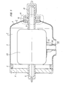
- the head housing 1 of a head current transformer 2 shown in FIG. 1 consists of a cylindrical part 3, a cap part 4 and a flange part 5.
- the cap part 4 is connected to the cylindrical part 3, for example by welding, while the flange part 5 is connected to an inner flange 6 of the cylindrical one Part 3 is screwed.
- One end 7 of a rod-shaped primary conductor is connected to the flange part 5 by welding.
- the housing 1 has an opening 9 in the area of the cap part 4, which opening is formed by a flange 10 welded to the cap part 4.
- the flange 10 has a circumferential groove 12 on a side 11 facing away from the housing 1, in which a sealing ring 13, preferably an O-ring, lies.
- the flange 10 also has a plurality of threaded bores 14 (see FIG. 2).
- a disk-shaped pressure element 15 is pressed onto the side 11 of the flange 10, as a result of which the sealing ring 13 becomes effective.
- the disc-shaped pressure element-15 has a central recess 16 through which a primary connection element 17 is guided, which is shown in the Embodiment of the other end of the rod-shaped primary conductor is shown.
- the disk-shaped pressure element 15 has a bevel 18 in which a radial sealing ring 19 is accommodated.
- a pressure plate 20 Arranged adjacent to the disk-shaped pressure element 15 is a pressure plate 20 which, like the disk-shaped pressure element, consists of an insulating material.
- the pressure plate 20, like the disk-shaped pressure element 15, has bores for receiving fastening screws 21.
- the pressure plate is provided with depressions 22 for receiving the screw head.
- the flange 10 is connected to the head housing 1 in the manner already described and in turn has an 11 on its side Sealing ring 13 on.
- a disk-shaped pressure element 30 is also in turn provided with a central recess 31 which, however, has two circumferential grooves 32 and 33 in its interior for receiving a radial sealing ring 34 and 35, respectively.
- the disk-shaped pressure element 30 is provided with a through bore 36 in order to achieve a bracing with the flange 10 by means of screws 37.
- the sealing point in the region of the connected with the housing 1 the flange 10 the latter "disk-shaped in the repeated manner described ausgestaltet.Ein pressure element 40 in turn has a central recess 41, the end of which a facing away from the head case 1 Has a bevel 42 for receiving a radial sealing ring 43.
- a pressure plate 44 is pressed against the disk-shaped pressure element 40 by means of screws 45.
- the pressure plate 44 is connected by means of a weld seam 46 to a primary connection element 47, which in the exemplary embodiment shown is not the end of a rod-shaped primary conductor, but rather a relatively short rod-shaped independent connection element, on the side 48 of this connection element 47 lying in the housing, the leads to a primary winding, for example accommodated in a foot housing, can then be fastened in a manner not shown.
- a primary connection element 47 which in the exemplary embodiment shown is not the end of a rod-shaped primary conductor, but rather a relatively short rod-shaped independent connection element, on the side 48 of this connection element 47 lying in the housing, the leads to a primary winding, for example accommodated in a foot housing, can then be fastened in a manner not shown.
- the pressure plate 44 therefore serves not only to accomplish the seal in the area of the primary connection element 47, but also simultaneously with the mechanical mounting of this connection element on the head housing 1.
- the disk-shaped pressure element 40 is provided with an axial projection 49, which serves to isolate the flange 10 and thus the head housing 1 from the primary connection element 47.
- Corresponding axial approaches also have the disk-shaped pressure elements of the exemplary embodiments according to FIGS. 1 to 3.
- FIG. 1 there is a core shell 50 in a known manner inside the head housing 1, which is fastened by means of a connecting member 51 to a metal tube 52 of a bushing 53, which is not shown in any further detail.
- a connecting member 51 to a metal tube 52 of a bushing 53, which is not shown in any further detail.
Priority Applications (1)
| Application Number | Priority Date | Filing Date | Title |
|---|---|---|---|
| AT81730029T ATE5925T1 (de) | 1980-03-27 | 1981-03-09 | Gas- oder fluessigkeitsisolierter messwandler. |
Applications Claiming Priority (2)
| Application Number | Priority Date | Filing Date | Title |
|---|---|---|---|
| DE3012165 | 1980-03-27 | ||
| DE3012165A DE3012165C2 (de) | 1980-03-27 | 1980-03-27 | Gas- oder flüssigkeitsisolierter Meßwandler |
Publications (2)
| Publication Number | Publication Date |
|---|---|
| EP0037367A1 true EP0037367A1 (fr) | 1981-10-07 |
| EP0037367B1 EP0037367B1 (fr) | 1984-01-18 |
Family
ID=6098699
Family Applications (1)
| Application Number | Title | Priority Date | Filing Date |
|---|---|---|---|
| EP81730029A Expired EP0037367B1 (fr) | 1980-03-27 | 1981-03-09 | Transformateur de mesure isolé par un gaz ou par un liquide |
Country Status (4)
| Country | Link |
|---|---|
| EP (1) | EP0037367B1 (fr) |
| AT (1) | ATE5925T1 (fr) |
| BR (1) | BR8101828A (fr) |
| DE (1) | DE3012165C2 (fr) |
Cited By (3)
| Publication number | Priority date | Publication date | Assignee | Title |
|---|---|---|---|---|
| EP0446837A1 (fr) * | 1990-03-16 | 1991-09-18 | Asea Brown Boveri Aktiengesellschaft | Transformateur traversant |
| CN103117162A (zh) * | 2011-11-17 | 2013-05-22 | 上海Mwb互感器有限公司 | 电流互感器的一次换接装置及电流互感器 |
| WO2013170874A1 (fr) * | 2012-05-14 | 2013-11-21 | Siemens Aktiengesellschaft | Ensemble traversée à plusieurs bornes |
Citations (5)
| Publication number | Priority date | Publication date | Assignee | Title |
|---|---|---|---|---|
| DE1014189B (de) * | 1954-12-13 | 1957-08-22 | Licentia Gmbh | Kopfarmatur einer Durchfuehrung fuer mit Isolierfluessigkeit gefuellte Gehaeuse elektrischer Geraete |
| FR1467894A (fr) * | 1965-12-21 | 1967-02-03 | Coq France | Dispositif de connexion à remplissage automatique pour matériel électrique par diélectrique liquide |
| US3380009A (en) * | 1967-03-10 | 1968-04-23 | Gen Electric | High voltage current transformer |
| US3935377A (en) * | 1974-12-24 | 1976-01-27 | Westinghouse Electric Corporation | Electrical bushing comprising a resin body and a ceramic outer shell |
| DE2814115A1 (de) * | 1978-03-09 | 1979-09-13 | Bbc Brown Boveri & Cie | Kombinierter strom- und spannungswandler fuer eine druckgasisolierte metallgekapselte hochspannungsanlage |
Family Cites Families (9)
| Publication number | Priority date | Publication date | Assignee | Title |
|---|---|---|---|---|
| DE975904C (de) * | 1952-02-13 | 1962-11-29 | Friedrich Dr-Ing E H Raupach | Einleiterstromwandler mit auf eine Sammelschiene aufsteckbarem Gehaeuse |
| DE971094C (de) * | 1953-10-21 | 1958-12-11 | Messwandler Bau Gmbh | Spannungswandler zum Anschluss an verschieden hohe Primaerspannungen |
| DE1488796A1 (de) * | 1965-08-19 | 1969-04-03 | Bbc Brown Boveri & Cie | Ring- oder rahmenfoermiger Aufsteckstromwandler |
| DE1563434C3 (de) * | 1966-11-23 | 1975-09-25 | Siemens Ag, 1000 Berlin Und 8000 Muenchen | Hochspannungsstromwandler |
| DE1563448B2 (de) * | 1966-12-27 | 1972-05-10 | Siemens AG, 1000 Berlin u. 8000 München | Hochspannungsstromwandler |
| DE2215928B2 (de) * | 1972-03-29 | 1975-10-30 | Siemens Ag, 1000 Berlin Und 8000 Muenchen | Spannungs-Meßeinrichtung für eine vollisolierte, metallgekapselte Hochspannungs-Schaltanlage |
| DE7632338U1 (de) * | 1976-10-14 | 1977-01-27 | Siemens Ag, 1000 Berlin Und 8000 Muenchen | Hochspannungsstromwandler mit einem metallenen, isoliergas- oder isolierfluessigkeitsgefuellten kopfgehaeuse |
| DE2658291B2 (de) * | 1976-12-22 | 1981-05-27 | WEMA Kunststoff- und Gerätebau GmbH & Co KG, Herstellung und Vertrieb von Kunststoffteilen, 8052 Moosburg | Durchführungsisolator |
| DE7914263U1 (de) * | 1979-05-17 | 1979-09-06 | Calor-Emag Elektrizitaets-Aktiengesellschaft, 4030 Ratingen | Stromwandler |
-
1980
- 1980-03-27 DE DE3012165A patent/DE3012165C2/de not_active Expired
-
1981
- 1981-03-09 EP EP81730029A patent/EP0037367B1/fr not_active Expired
- 1981-03-09 AT AT81730029T patent/ATE5925T1/de active
- 1981-03-26 BR BR8101828A patent/BR8101828A/pt unknown
Patent Citations (5)
| Publication number | Priority date | Publication date | Assignee | Title |
|---|---|---|---|---|
| DE1014189B (de) * | 1954-12-13 | 1957-08-22 | Licentia Gmbh | Kopfarmatur einer Durchfuehrung fuer mit Isolierfluessigkeit gefuellte Gehaeuse elektrischer Geraete |
| FR1467894A (fr) * | 1965-12-21 | 1967-02-03 | Coq France | Dispositif de connexion à remplissage automatique pour matériel électrique par diélectrique liquide |
| US3380009A (en) * | 1967-03-10 | 1968-04-23 | Gen Electric | High voltage current transformer |
| US3935377A (en) * | 1974-12-24 | 1976-01-27 | Westinghouse Electric Corporation | Electrical bushing comprising a resin body and a ceramic outer shell |
| DE2814115A1 (de) * | 1978-03-09 | 1979-09-13 | Bbc Brown Boveri & Cie | Kombinierter strom- und spannungswandler fuer eine druckgasisolierte metallgekapselte hochspannungsanlage |
Cited By (4)
| Publication number | Priority date | Publication date | Assignee | Title |
|---|---|---|---|---|
| EP0446837A1 (fr) * | 1990-03-16 | 1991-09-18 | Asea Brown Boveri Aktiengesellschaft | Transformateur traversant |
| CN103117162A (zh) * | 2011-11-17 | 2013-05-22 | 上海Mwb互感器有限公司 | 电流互感器的一次换接装置及电流互感器 |
| CN103117162B (zh) * | 2011-11-17 | 2016-08-10 | 上海Mwb互感器有限公司 | 电流互感器的一次换接装置及电流互感器 |
| WO2013170874A1 (fr) * | 2012-05-14 | 2013-11-21 | Siemens Aktiengesellschaft | Ensemble traversée à plusieurs bornes |
Also Published As
| Publication number | Publication date |
|---|---|
| EP0037367B1 (fr) | 1984-01-18 |
| BR8101828A (pt) | 1981-09-29 |
| DE3012165C2 (de) | 1983-09-01 |
| ATE5925T1 (de) | 1984-02-15 |
| DE3012165A1 (de) | 1981-10-01 |
Similar Documents
| Publication | Publication Date | Title |
|---|---|---|
| DE2740695C2 (de) | Überspannungsableiter mit einer Gasentladungsröhren-Funkenstrecke und mit einer parallel geschalteten Hilfsfunkenstrecke | |
| DE3401377C2 (de) | Elektromagnetischer Durchflußmesser | |
| DE3008147C2 (de) | Gabelkopfgelenk, insbesondere zum Anlenken einer Ladeschaufel an den Tragarm einer Ladeschwinge | |
| CH668476A5 (de) | Elektromagnetischer durchflussmesser. | |
| DE3907190A1 (de) | Zuendkerze mit drucksensor | |
| DE3423921C2 (fr) | ||
| DE2634766B2 (fr) | ||
| DE2836976A1 (de) | Buerstenanordnung fuer elektromotoren sowie verfahren zur montage einer buerstenanordnung | |
| EP0037367B1 (fr) | Transformateur de mesure isolé par un gaz ou par un liquide | |
| DE3540547C2 (fr) | ||
| DE3331462C2 (fr) | ||
| DE2620269A1 (de) | Elektromagnet | |
| DE2220548C2 (de) | Schauglasanordnung für Druckbehälter | |
| DE2453845C3 (de) | Wanderfeldröhre | |
| EP0134525B1 (fr) | Traversée électrique à haute tension pour un appareil électrique enfermé dans un boîtier | |
| DE3500767C2 (fr) | ||
| DE2325438B2 (de) | Spannungswandler für vollisolierte, metallgekapselte Hochspannungsschaltanlagen | |
| DE8407659U1 (de) | Druck- oder druckdifferenzmessgeraet | |
| DE857664C (de) | Anordnung zur Befestigung der am Anodeneinfuehrungsisolator eines Stromrichters aufgehaengten Lichtbogenfuehrungshuelse | |
| CH620044A5 (en) | High-voltage current transformer with a metallic head housing filled with insulating gas or insulating fluid | |
| DE1564437C3 (de) | Elektrische Entladungsröhre mit einer Gasfüllung und mit einer Metallwand, in der mindestens eine Elektrode durch keramische Körper isoliert und vakuumdicht befestigt ist | |
| AT236528B (de) | Halbleiterbauelement und Vorrichtung für die Herstellung eines solchen Halbleiterbauelementes | |
| DE355398C (de) | Vorrichtung zur Verwendung von Sicherungsschraubstoepseln bei Sicherungen mit Mittelkontaktbolzen | |
| DE1053611B (de) | Anordnung zur Befestigung von saeulenartig zusammengesetzten Schaltelementen, wie Pupinspulen, in Behaeltern, insbesondere in Muffen | |
| EP0044802A1 (fr) | Dispositif à résistance comportant des éléments résistifs annulaires empilés ayant un axe commun |
Legal Events
| Date | Code | Title | Description |
|---|---|---|---|
| PUAI | Public reference made under article 153(3) epc to a published international application that has entered the european phase |
Free format text: ORIGINAL CODE: 0009012 |
|
| AK | Designated contracting states |
Designated state(s): AT CH GB IT SE |
|
| 17P | Request for examination filed |
Effective date: 19811028 |
|
| ITF | It: translation for a ep patent filed |
Owner name: STUDIO JAUMANN |
|
| GRAA | (expected) grant |
Free format text: ORIGINAL CODE: 0009210 |
|
| AK | Designated contracting states |
Designated state(s): AT CH GB IT LI SE |
|
| REF | Corresponds to: |
Ref document number: 5925 Country of ref document: AT Date of ref document: 19840215 Kind code of ref document: T |
|
| PGFP | Annual fee paid to national office [announced via postgrant information from national office to epo] |
Ref country code: SE Payment date: 19840331 Year of fee payment: 4 |
|
| PGFP | Annual fee paid to national office [announced via postgrant information from national office to epo] |
Ref country code: CH Payment date: 19840625 Year of fee payment: 4 |
|
| PLBI | Opposition filed |
Free format text: ORIGINAL CODE: 0009260 |
|
| 26 | Opposition filed |
Opponent name: MWB MESSWANDLER-BAU AG Effective date: 19841004 |
|
| PG25 | Lapsed in a contracting state [announced via postgrant information from national office to epo] |
Ref country code: GB Effective date: 19860309 |
|
| GBPC | Gb: european patent ceased through non-payment of renewal fee | ||
| PGFP | Annual fee paid to national office [announced via postgrant information from national office to epo] |
Ref country code: AT Payment date: 19870227 Year of fee payment: 7 |
|
| RDAG | Patent revoked |
Free format text: ORIGINAL CODE: 0009271 |
|
| STAA | Information on the status of an ep patent application or granted ep patent |
Free format text: STATUS: PATENT REVOKED |
|
| 27W | Patent revoked |
Effective date: 19871007 |
|
| REG | Reference to a national code |
Ref country code: CH Ref legal event code: PL |
|
| GBPR | Gb: patent revoked under art. 102 of the ep convention designating the uk as contracting state | ||
| EUG | Se: european patent has lapsed |
Ref document number: 81730029.6 Effective date: 19881205 |
|
| APAH | Appeal reference modified |
Free format text: ORIGINAL CODE: EPIDOSCREFNO |