EP0037367A1 - Gas or liquid insulated measuring transformer - Google Patents
Gas or liquid insulated measuring transformer Download PDFInfo
- Publication number
- EP0037367A1 EP0037367A1 EP81730029A EP81730029A EP0037367A1 EP 0037367 A1 EP0037367 A1 EP 0037367A1 EP 81730029 A EP81730029 A EP 81730029A EP 81730029 A EP81730029 A EP 81730029A EP 0037367 A1 EP0037367 A1 EP 0037367A1
- Authority
- EP
- European Patent Office
- Prior art keywords
- shaped
- sealing ring
- flange
- connection element
- pressure element
- Prior art date
- Legal status (The legal status is an assumption and is not a legal conclusion. Google has not performed a legal analysis and makes no representation as to the accuracy of the status listed.)
- Granted
Links
Images

Classifications
-
- H—ELECTRICITY
- H01—ELECTRIC ELEMENTS
- H01F—MAGNETS; INDUCTANCES; TRANSFORMERS; SELECTION OF MATERIALS FOR THEIR MAGNETIC PROPERTIES
- H01F27/00—Details of transformers or inductances, in general
- H01F27/02—Casings
- H01F27/04—Leading of conductors or axles through casings, e.g. for tap-changing arrangements
-
- H—ELECTRICITY
- H01—ELECTRIC ELEMENTS
- H01F—MAGNETS; INDUCTANCES; TRANSFORMERS; SELECTION OF MATERIALS FOR THEIR MAGNETIC PROPERTIES
- H01F38/00—Adaptations of transformers or inductances for specific applications or functions
- H01F38/20—Instruments transformers
- H01F38/22—Instruments transformers for single phase ac
- H01F38/28—Current transformers
- H01F38/30—Constructions
- H01F2038/305—Constructions with toroidal magnetic core
Definitions
- the invention relates to a gas or liquid insulated transducer with a head housing, which has an opening for receiving at least one rod-shaped primary connection element, the housing in the region of the opening carrying a flange which is insulated from the primary connection element by an insulating ring part and has on its side facing away from the housing a sealing ring against which a disk-shaped pressure element is pressed with a central recess dimensioned in accordance with the dimensions of the primary connecting element.
- a known transducer of this type (US Pat. No. 3,380,009) is designed as a top current transformer and has a rod-shaped primary conductor.
- the ends of the rod-shaped primary conductor form rod-shaped primary connection elements of the transducer.
- the rod-shaped primary conductor is welded at one end to a flange which, with the interposition of an annular seal, is screwed to a welded-in flange of the head housing.
- the primary conductor is galvanically isolated from the head housing and sealed through an opening in the head housing.
- the head housing is provided in the region of its opening with a welded-in flange which is insulated from the end of the rod-shaped primary conductor which forms the primary connecting element by an insulating ring part.
- the flange also faces away from the housing.
- This disk-shaped pressure element is formed by a kind of nut which has a recess with a thread. So that the mother is on the end of the rod-shaped primary lead provided with an external thread. ter screwed, whereby the flange of the housing is clamped not only with the disc-shaped pressure element via the sealing ring, but also via a further inner sealing ring with a stop located inside the housing on the rod-shaped primary conductor.
- connection point of the end of the rod-shaped primary conductor forming the rod-shaped primary connection element with the housing on the side is relatively complicated, where the head housing must also be insulated from the primary connection element.
- the rod-shaped primary conductor changes in length as a result of heating, the head housing is subjected to a load because it is then deflected laterally.
- the invention is therefore based on the object of proposing a gas- or liquid-insulated transducer with a head housing in which the connection point between the head housing and the rod-shaped primary connection element can also be designed simply where insulation between the head housing and the primary connection element is required .
- this connection point should be designed so that no mechanical stress is exerted on the head housing by the primary connection element and its connection even if the primary connection element forms the end of a rod-shaped primary conductor penetrating the head housing.
- the disk-shaped pressure element consists of an insulating material and has at least one radial sealing ring in the region of its central recess.
- a major advantage of the transducer according to the invention is that a tensioning of the primary connection element with the head housing is not required to seal the opening of the head housing; there is therefore no need for a stop in the interior of the head housing on the rod-shaped primary connection element, which is required in the known current transformer to avoid mechanical stress on the head housing.
- the primary connection element is not clamped at all in the transducer according to the invention in the area of the opening in the head housing because the head housing is sealed in the area of the primary connection element in addition to the sealing ring on the flange by at least one radial sealing ring in the area of the center recess.
- transducer according to the invention is relatively simple in the area of the primary connection element because the primary connection element does not have to be provided with an external thread and the disk-shaped pressure element in its central recess does not have to be provided with an internal thread; Both the primary connection element and the disk-shaped pressure element can be designed as a straight cylinder with respect to its central recess.
- the transducer according to the invention does not require a stop in the interior of the head housing on the primary connection element, which not only saves on components, but also on manufacturing costs.
- the attachment of the radial sealing ring may take place at the e r f indungsnostiencStromwandler in the center recess of the disc-shaped pressure element in different ways.
- the disk-shaped pressure element has at least one circumferential groove with a radial sealing ring in the interior of its central recess and if the disk-shaped pressure element is clamped to the flange by several screws.
- Two circumferential grooves, each with a radial sealing ring, are preferably provided one behind the other in the recess.
- the particular advantage of this embodiment is that the seal in the area of the opening of the head housing is completed by fastening the disk-shaped pressure element to the flange.
- the disk-shaped pressure element has a circumferential bevel at the end of the center recess facing away from the head housing, in which a radial sealing ring lies; a pressure plate is pressed against the radial sealing ring.
- the advantage of this embodiment is that the receptacle for the radial sealing ring can be manufactured comparatively easily; the pressure plate proves to be an additional expense, since the seal can only become effective in the pressed state.
- the pressure plate can be designed in different ways. It is considered advantageous if it consists of an insulating material and is clamped to the flange and the disk-shaped pressure element by a plurality of screws. In this case, both the disk-shaped pressure element and the pressure plate can be clamped to the flange of the head housing using the screws.
- the pressure plate consists of metal and is welded to the primary connection element; the pressure plate is attached to the disc-shaped pressure element, which in turn is clamped to the flange.
- the primary connection element is not formed by the end of a rod-shaped primary conductor of a head current transformer, but rather is an independent, relatively short rod-shaped connection element of a transformer, at the end of which in the head housing, for example, the feeds to one are fixed in a pot housing housed primary winding.
- the disk-shaped pressure element bears an axial extension which forms the insulating ring part. In this way, the number of components required to construct the transducer according to the invention can be reduced.
- the primary connection element and an opposite further primary connection element can form the ends of a rod-shaped primary conductor and, due to the described attachment of the primary connection element in the opening of the head housing, the cylindrical housing with its Axis in the direction parallel to the rod-shaped primary conductor.
- the rod-shaped primary conductor can only be installed from the outside; an intervention from inside to possibly regulate the position of a spacer element, as is required in the known current transformer described above, must not be made here, so that the head housing of the transducer according to the invention does not have to be divided in the horizontal direction.
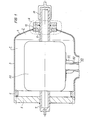
- the head housing 1 of a head current transformer 2 shown in FIG. 1 consists of a cylindrical part 3, a cap part 4 and a flange part 5.
- the cap part 4 is connected to the cylindrical part 3, for example by welding, while the flange part 5 is connected to an inner flange 6 of the cylindrical one Part 3 is screwed.
- One end 7 of a rod-shaped primary conductor is connected to the flange part 5 by welding.
- the housing 1 has an opening 9 in the area of the cap part 4, which opening is formed by a flange 10 welded to the cap part 4.
- the flange 10 has a circumferential groove 12 on a side 11 facing away from the housing 1, in which a sealing ring 13, preferably an O-ring, lies.
- the flange 10 also has a plurality of threaded bores 14 (see FIG. 2).
- a disk-shaped pressure element 15 is pressed onto the side 11 of the flange 10, as a result of which the sealing ring 13 becomes effective.
- the disc-shaped pressure element-15 has a central recess 16 through which a primary connection element 17 is guided, which is shown in the Embodiment of the other end of the rod-shaped primary conductor is shown.
- the disk-shaped pressure element 15 has a bevel 18 in which a radial sealing ring 19 is accommodated.
- a pressure plate 20 Arranged adjacent to the disk-shaped pressure element 15 is a pressure plate 20 which, like the disk-shaped pressure element, consists of an insulating material.
- the pressure plate 20, like the disk-shaped pressure element 15, has bores for receiving fastening screws 21.
- the pressure plate is provided with depressions 22 for receiving the screw head.
- the flange 10 is connected to the head housing 1 in the manner already described and in turn has an 11 on its side Sealing ring 13 on.
- a disk-shaped pressure element 30 is also in turn provided with a central recess 31 which, however, has two circumferential grooves 32 and 33 in its interior for receiving a radial sealing ring 34 and 35, respectively.
- the disk-shaped pressure element 30 is provided with a through bore 36 in order to achieve a bracing with the flange 10 by means of screws 37.
- the sealing point in the region of the connected with the housing 1 the flange 10 the latter "disk-shaped in the repeated manner described ausgestaltet.Ein pressure element 40 in turn has a central recess 41, the end of which a facing away from the head case 1 Has a bevel 42 for receiving a radial sealing ring 43.
- a pressure plate 44 is pressed against the disk-shaped pressure element 40 by means of screws 45.
- the pressure plate 44 is connected by means of a weld seam 46 to a primary connection element 47, which in the exemplary embodiment shown is not the end of a rod-shaped primary conductor, but rather a relatively short rod-shaped independent connection element, on the side 48 of this connection element 47 lying in the housing, the leads to a primary winding, for example accommodated in a foot housing, can then be fastened in a manner not shown.
- a primary connection element 47 which in the exemplary embodiment shown is not the end of a rod-shaped primary conductor, but rather a relatively short rod-shaped independent connection element, on the side 48 of this connection element 47 lying in the housing, the leads to a primary winding, for example accommodated in a foot housing, can then be fastened in a manner not shown.
- the pressure plate 44 therefore serves not only to accomplish the seal in the area of the primary connection element 47, but also simultaneously with the mechanical mounting of this connection element on the head housing 1.
- the disk-shaped pressure element 40 is provided with an axial projection 49, which serves to isolate the flange 10 and thus the head housing 1 from the primary connection element 47.
- Corresponding axial approaches also have the disk-shaped pressure elements of the exemplary embodiments according to FIGS. 1 to 3.
- FIG. 1 there is a core shell 50 in a known manner inside the head housing 1, which is fastened by means of a connecting member 51 to a metal tube 52 of a bushing 53, which is not shown in any further detail.
- a connecting member 51 to a metal tube 52 of a bushing 53, which is not shown in any further detail.
Abstract
Description
Die Erfindung bezieht sich auf einen gas- oder flüssigkeitsisolierten Meßwandler mit einem Kopfgehäuse, das eine Öffnung zur Aufnahme mindestens eines stabförmigen primären Anschlußelementes aufweist, wobei das Gehäuse im Bereich der Öffnung einen Flansch trägt, der durch ein isolierendes Ringteil gegenüber dem primären Anschlußelement isoliert ist und an seiner vomGehäuse abgewandten Seite einen Dichtungsring aufweist, gegen den ein scheibenförmiges Druckelement mit einer den Abmessungen des primären Anschlußelementes entsprechend bemessenen Mittenausnehmung gepreßt ist.The invention relates to a gas or liquid insulated transducer with a head housing, which has an opening for receiving at least one rod-shaped primary connection element, the housing in the region of the opening carrying a flange which is insulated from the primary connection element by an insulating ring part and has on its side facing away from the housing a sealing ring against which a disk-shaped pressure element is pressed with a central recess dimensioned in accordance with the dimensions of the primary connecting element.
Ein bekannter Meßwandler dieser Art (US-PS 3 380 009) ist als Kopfstromwandler ausgebildet und weist einen stabförmigen Primärleiter auf. Die Enden des stabförmigen Primärleiters bilden stabförmige primäre Anschlußelemente'des Wandlers. Der stabförmige Primärleiter ist an einem Ende mit einem Flansch verschweißt, der unter Zwischenlage einer ringförmigen Dichtung mit einem eingeschweißten Flansch des Kopfgehäuses verschraubt ist. An seinem anderen Ende ist der Primärleiter galvanisch vom Kopfgehäuse isoliert und abgedichtet durch eine Öffnung des Kopfgehäuses geführt.A known transducer of this type (US Pat. No. 3,380,009) is designed as a top current transformer and has a rod-shaped primary conductor. The ends of the rod-shaped primary conductor form rod-shaped primary connection elements of the transducer. The rod-shaped primary conductor is welded at one end to a flange which, with the interposition of an annular seal, is screwed to a welded-in flange of the head housing. At its other end, the primary conductor is galvanically isolated from the head housing and sealed through an opening in the head housing.
Das Kopfgehäuse ist zu diesem Zwecke im Bereich seiner Öffnung mit einem eingeschweißten Flansch versehen, der durch ein isolierendes Ringteil gegenüber dem das primäre Anschlußelement bildenden Ende des stabförmigen Primärleiters isoliert ist. Der Flansch weist außerdem an seiner vom Gehäuse abgewandten. Seite einen Dichtungsring auf, gegen den ein scheibenförmiges Druckelement gepreßt ist. Dieses scheibenförmige Druckelement ist von einer Art Mutter gebildet, die eine Ausnehmung mit einem Gewinde aufweist. Damit wird die Mutter auf das mit einem Außengewinde versehene Ende des stabförmigen Primärlei-. ters geschraubt, wodurch der Flansch des Gehäuses über den Dichtring nicht nur mit dem scheibenförmigen Druckelement verspannt wird, sondern über einen weiteren inneren Dichtring auch mit einem Anschlag, der sich innerhalb des Gehäuses auf dem stabförmigen Primärleiter befindet.For this purpose, the head housing is provided in the region of its opening with a welded-in flange which is insulated from the end of the rod-shaped primary conductor which forms the primary connecting element by an insulating ring part. The flange also faces away from the housing. Side on a sealing ring against which a disc-shaped pressure element is pressed. This disk-shaped pressure element is formed by a kind of nut which has a recess with a thread. So that the mother is on the end of the rod-shaped primary lead provided with an external thread. ter screwed, whereby the flange of the housing is clamped not only with the disc-shaped pressure element via the sealing ring, but also via a further inner sealing ring with a stop located inside the housing on the rod-shaped primary conductor.
Bei dem bekannten Meßwandler ist die Verbindungsstelle des das stabförmige primäre Anschlußelement bildenden Endes des stabförmigen Primärleiters mit dem Gehäuse auf der Seite verhältnismäßig kompliziert, wo auch eine Isolierung des Kopfgehäuses vom primären Anschlußelement vorgesehen sein muß. Außerdem tritt bei Längenänderungen des stabförmigen Primärleiters infolge Erwärmung eine Belastung des Kopfgehäuses ein, weil dieses dann seitlich ausgelenkt wird.In the known transducer, the connection point of the end of the rod-shaped primary conductor forming the rod-shaped primary connection element with the housing on the side is relatively complicated, where the head housing must also be insulated from the primary connection element. In addition, when the rod-shaped primary conductor changes in length as a result of heating, the head housing is subjected to a load because it is then deflected laterally.
Der Erfindung liegt daher die Aufgabe zugrunde, einen gas- oder flüssigkeitsisolierten Meßwandler mit einem Kopfgehäuse vorzuschlagen, bei dem die Verbindungsstelle zwischen dem Kopfgehäuse und dem stabförmigen primären Anschlußelement auch dort einfach ausgestaltet werden kann, wo eine Isolierung zwischen dem Kopfgehäuse und dem primären Anschlußelement erforderlich ist. Außerdem soll diese Verbindungsstelle so gestaltet werden, daß durch das primäre Anschlußelement und seine Verbindung selbst dann keine mechanische Belastung auf das Kopfgehäuse ausgeübt wird, wenn das primäre Anschlußelement das Ende eines das Kopfgehäuse durchsetzendenstabförmigen Primärleiters bildet.The invention is therefore based on the object of proposing a gas- or liquid-insulated transducer with a head housing in which the connection point between the head housing and the rod-shaped primary connection element can also be designed simply where insulation between the head housing and the primary connection element is required . In addition, this connection point should be designed so that no mechanical stress is exerted on the head housing by the primary connection element and its connection even if the primary connection element forms the end of a rod-shaped primary conductor penetrating the head housing.
Zur Lösung dieser Aufgabe besteht bei einem gas- oder flüssigkeitsisolierten Meßwandler der eingangs angegebenen Art erfindungsgemäß das scheibenförmige Druckelement aus einem isolierenden Werkstoff und weist im Bereich seiner Mittenausnehmung mindestens einen Radialdichtring auf.To achieve this object, in the case of a gas or liquid-insulated measuring transducer of the type specified at the outset, the disk-shaped pressure element consists of an insulating material and has at least one radial sealing ring in the region of its central recess.
Ein wesentlicher Vorteil des erfindungsgemäßen Meßwandlers besteht darin, daß zur Abdichtung der Öffnung des Kopfgehäuses eine Verspannung des primären Anschlußelementes mit dem Kopfgehäuse nicht erforderlich ist; es bedarf deshalb auch im Innern des Kopfgehäuses auf dem stabförmigen primären Anschlußelementes eines Anschlages nicht, der bei dem bekannten Stromwandler zur Vermeidung einer mechanischen Beanspruchung des Kopfgehäuses erforderlich ist. Das primäre Anschlußelement ist bei dem erfindungsgemäßen Meßwandler im Bereich der Öffnung im Kopfgehäuse überhaupt nicht verspannt, weil die Abdichtung des Kopfgehäuses im Bereich des primären Anschlußelementes außer dem Dichtring am Flansch durch mindestens einen Radialdichtring im Bereich der Mittenausnehmung erfolgt. Ein weiterer wesentlicher Vorteil des erfindungsgemäßen Meßwandlers ist darin zu sehen, daß er im Bereich des primären Anschlußelementes verhältnismäßig einfach ausgebildet ist, weil das primäre Anschlußelement nicht mit einem Außengewinde und das scheibenförmige Druckelement in seiner Mittenausnehmung nicht mit einem Innengewinde versehen sein muß; sowohl das primäre Anschlußelement als auch das scheibenförmige Druckelement kann bezüglich seiner Mittenausnehmung als gerader Zylinder ausgeführt sein. Außerdem benötigt der erfindungsgemäße Meßwandler im Innern des Kopfgehäuse auf dem primären Anschlußelement keinen Anschlag, wodurch nicht nur an Bauelementen, sondern auch an Herstellungskosten gespart ist.A major advantage of the transducer according to the invention is that a tensioning of the primary connection element with the head housing is not required to seal the opening of the head housing; there is therefore no need for a stop in the interior of the head housing on the rod-shaped primary connection element, which is required in the known current transformer to avoid mechanical stress on the head housing. The primary connection element is not clamped at all in the transducer according to the invention in the area of the opening in the head housing because the head housing is sealed in the area of the primary connection element in addition to the sealing ring on the flange by at least one radial sealing ring in the area of the center recess. Another significant advantage of the transducer according to the invention is that it is relatively simple in the area of the primary connection element because the primary connection element does not have to be provided with an external thread and the disk-shaped pressure element in its central recess does not have to be provided with an internal thread; Both the primary connection element and the disk-shaped pressure element can be designed as a straight cylinder with respect to its central recess. In addition, the transducer according to the invention does not require a stop in the interior of the head housing on the primary connection element, which not only saves on components, but also on manufacturing costs.
Die Anbringung des Radialdichtringes kann bei dem erfindungsgemäßencStromwandler im Bereich der Mittenausnehmung des scheibenförmigen Druckelementes in unterschiedlicher Weise erfolgen. Als vorteilhaft wird es jedoch angesehen, wenn das scheibenförmige Druckelement im Innern seiner Mittenausnehmung mindestens eine umlaufende Nut mit einem Radialdichtring aufweist und wenn das scheibenförmigen Druckelement durch mehrere Schrauben mit dem Flansch verspannt ist. Vorzugsweise sind zwei umlaufende Nuten mit jeweils einem Radialdichtring hintereinander in der Ausnehmung vorgesehen. Der besnndere Vorzug dieser Ausführungsform besteht darin, daß durch Befestigung des scheibenförmigen Druckelementes an dem Flansch die Dichtung im Bereich der Öffrung des Kopfgehäuses vervollständigt ist.The attachment of the radial sealing ring may take place at the e r f indungsgemäßencStromwandler in the center recess of the disc-shaped pressure element in different ways. However, it is considered to be advantageous if the disk-shaped pressure element has at least one circumferential groove with a radial sealing ring in the interior of its central recess and if the disk-shaped pressure element is clamped to the flange by several screws. Two circumferential grooves, each with a radial sealing ring, are preferably provided one behind the other in the recess. The particular advantage of this embodiment is that the seal in the area of the opening of the head housing is completed by fastening the disk-shaped pressure element to the flange.
Als vorteilhaft wird es ferner angesehen, wenn das scheibenförmige Druckelement an dem vom Kopfgehäuse abgewendeten Ende der Mittenausnehmung eine umlaufende Abschrägung aufweist, in der ein Radialdichtring liegt; gegen den Radialdichtring ist eine Druckplatte gepreßt. Der Vorteil dieser Ausführungsform liegt darin, daß die Aufnahme für den Radialdichtring vergleichsweise einfach hergestellt werden kann; als zusätzlicher Aufwand erweist sich hierbei die Druckplatte, die im angepreßten Zustand erst die Dichtung wirksam werden läßt.It is also considered to be advantageous if the disk-shaped pressure element has a circumferential bevel at the end of the center recess facing away from the head housing, in which a radial sealing ring lies; a pressure plate is pressed against the radial sealing ring. The advantage of this embodiment is that the receptacle for the radial sealing ring can be manufactured comparatively easily; the pressure plate proves to be an additional expense, since the seal can only become effective in the pressed state.
Die Druckplatte kann in unterschiedlicher Weise ausgebildet sein. Als vorteilhaft wird es angesehen, wenn sie aus einem isolierenden Werkstoff besteht und durch mehrere Schrauben mit dem Flansch und dem scheibenförmigen Druckelement verspannt ist. In diesem Falle können mit den Schrauben sowohl das scheibenförmige Druckelement als auch die Druckplatte mit dem Flansch des Kopfgehäuses verspannt werden.The pressure plate can be designed in different ways. It is considered advantageous if it consists of an insulating material and is clamped to the flange and the disk-shaped pressure element by a plurality of screws. In this case, both the disk-shaped pressure element and the pressure plate can be clamped to the flange of the head housing using the screws.
Es kann aber auch vorteilhaft sein, wenn die Druckplatte aus Metall besteht und mit dem primären Anschlußelement verschweißt ist; die Druckplatte ist an dem scheibenförmigen Druckelement befestigt, das seinerseits mit dem Flansch verspannt ist. Einer derartigen Ausführung wird man beispielsweise dann den Vorzug geben, wenn das primäre Anschlußelement nicht von dem Ende eines stabförmigen Primärleiters eines Kopfstromwandlers gebildet ist, sondern ein selbständiges, verhältnismäßig kurzes stabförmiges Anschlußelement eines Wandlers darstellt, an dessem im Kopfgehäuse liegenden Ende beispielsweise die Zuführungen zu einer in einem Topfgehäuse untergebrachten Primärwicklung befestigt sind.However, it can also be advantageous if the pressure plate consists of metal and is welded to the primary connection element; the pressure plate is attached to the disc-shaped pressure element, which in turn is clamped to the flange. Such an embodiment will be preferred, for example, if the primary connection element is not formed by the end of a rod-shaped primary conductor of a head current transformer, but rather is an independent, relatively short rod-shaped connection element of a transformer, at the end of which in the head housing, for example, the feeds to one are fixed in a pot housing housed primary winding.
Bei dem erfindungsgemäßen Meßwandler hat es sich auch als vorteilhaft erwiesen, wenn das scheibenförmige Druckelement einen axialen Ansatz trägt, der das isolierende Ringteil bildet. Auf diese Weise läßt sich die Zahl der zum Aufbau des erfindungsgemäßen Meßwandlers erforderlichen Bauteile senken.In the transducer according to the invention, it has also proven to be advantageous if the disk-shaped pressure element bears an axial extension which forms the insulating ring part. In this way, the number of components required to construct the transducer according to the invention can be reduced.
Bei einem als Stromwandler mit einem zylindrischen Kopfgehäuse ausgebildeten erfindungsgemäßen Meßwandler können in an sich bekannter Weise das primäre Anschlußelement und ein gegenüberliegendes weiteres primäres Anschlußelement die Enden eines stabförmigen Primärleiters bilden und aufgrund der beschriebenen Anbringung des primären Anschlußelementes in der Öffnung des Kopfgehäuses das zylindrische Gehäuse mit seiner Achse in paralleler Richtung zum stabförmigen Primärleiter angebracht sein. Die Montage des stabförmigen Primärleiters kann nämlich ausschließlich von außen erfolgen; ein Eingriff von innen zum möglicherweise erforderlichen Regulieren der Stellung eines Abstandselementes, wie dies bei dem oben beschriebenen bekannten Stromwandler erforderlich ist, muß hier auf keinen Fall vorgenommen werden, so daß das Kopfgehäuse des erfindungsgemäßen Meßwandlers nicht in horizontaler Richtung geteilt sein muß.In a transducer according to the invention designed as a current transformer with a cylindrical head housing, the primary connection element and an opposite further primary connection element can form the ends of a rod-shaped primary conductor and, due to the described attachment of the primary connection element in the opening of the head housing, the cylindrical housing with its Axis in the direction parallel to the rod-shaped primary conductor. The rod-shaped primary conductor can only be installed from the outside; an intervention from inside to possibly regulate the position of a spacer element, as is required in the known current transformer described above, must not be made here, so that the head housing of the transducer according to the invention does not have to be divided in the horizontal direction.
Zur Erläuterung der Erfindung ist in
- Fig. 1 das Kopfgehäuse eines als Kopfstromwandler ausgebildeten Ausführungsbeispiels des erfindungsgemäßen Meßwandlers, in
- Fig. 2 die Einzelheit A nach Fig. 1 vergrößert, in
- Fig. 3 eine weitere Ausbildungsmöglichkeit der Verbindungsstelle im Bereich der Einzelheit A und in
- Fig. 4 eine weitere Ausführungsform der Verbindungsstelle im Bereich der Einzelheit A wiedergegeben.
- Fig. 1 shows the head housing of an embodiment of the transducer according to the invention designed as a head current transformer, in
- Fig. 2 enlarged the detail A of FIG. 1, in
- Fig. 3 shows another training possibility of the junction in the area of detail A and in
- Fig. 4 shows a further embodiment of the connection point in the area of detail A.
Das in Fig. 1 dargestellte Kopfgehäuse 1 eines Kopfstromwandlers 2 besteht aus einem zylindrischen Teil 3,einem Kappenteil 4 und einem Flanschteil 5. Das Kappenteil 4 ist mit dem zylindrischen Teil 3 beispielsweise durch Schweißen verbunden, während das Flanschteil 5 mit einem Innenflansch 6 des zylindrischen Teils 3 verschraubt ist. Mit dem Flanschteil 5 ist ein Ende 7 eines stabförmigen Primärleiters durch Schweißen verbunden.The head housing 1 of a head
Das Gehäuse 1 weist im Bereich des Kappenteiles 4 eine Öffnung 9 auf, die von einem an dem Kappenteil 4 angeschweißten Flansch 10 gebildet ist. Der Flansch 10 weist auf einer vom Gehäuse 1 abgewendeten Seite 11 eine umlaufende Nut 12 auf, in der ein Dichtring 13, vorzugsweise ein O-Ring, liegt. Der Flansch 10 weist außerdem mehrere Gewindebohrungen 14 auf(siehe Fig.2).The housing 1 has an opening 9 in the area of the cap part 4, which opening is formed by a
An die Seite 11 des Flansches 10 ist ein scheibenförmiges Druckelement 15 gepreßt, wodurch der Dichtring .-13 wirksam wird. Das scheibenförmige Druckelement-15 besitzt eine Mittenausnehmung 16, durch die ein primäres Anschlußelement 17 geführt ist, das in dem dargestellten Ausführungsbeispiel von dem anderen Ende des stabförmigen Primärleiters abgebildet ist. An dem vom Kopfgehäuse 1 abgewandten Ende der Mittenausnehmung 16 weist das scheibenförmige Druckelement 15 eine Abschrägung 18 auf, in der ein Radialdichtring 19 untergebracht ist.A disk-
Dem scheibenförmigen Druckelement 15 benachbart ist eine Druckplatte 20 angeordnet, die ebenso wie das scheibenförmige Druckelement aus einem isolierenden Werkstoff besteht. Die Druckplatte 20 weist ebenso wie das scheibenförmige Druckelement 15 Bohrungen zur Aufnahme von Befestigungsschrauben 21 auf. Zur Aufnahme des Schraubenkopfes ist die Druckplatte mit Einsenkungen 22 versehen. Nach Eindrehen der Schrauben 21 sind das scheibenförmige Druckelement 15 und die Druckplatte 20 mit dem Flansch 10 verspannt, wobei das Kopfgehäuse 1 sowohl an der Seite 11 des Flansches 10 als auch im Bereich des primären Anschlußelementes 17 nach außen sicher abgedichtet ist. Dabeijst die Abdichtung ohne jegliche Verspannung des Gehäuses 1 erreicht, weil an dem Flansch 10 lediglich das scheibenförmige Druckelement 15 und die Druckplatte 20 befestigt werden, die jedoch nicht an dem primären Anschlußelement 17 angreifen. In dem dargestellten Fall des Kopfstromwandlers mit einem stabförmigen Primärleiter hat diese Art der Ausbildung der Dichtungsstelle außerdem den Vorteil, daß sich bei einer infolge Stromdurchflusses erfolgenden Erwärmung der Primärleiter in axialer Richtung ausdehnen kann, ohne daß dadurch das Gehäuse 1 beansprucht wird.Arranged adjacent to the disk-
Bei der Dichtungsstelle nach Fig. 3 ist der Flansch 10 in der schon beschriebenen Weise mit dem Kopfgehäuse 1 verbunden und weist wiederum an seiner Seite 11 einen Dichtring 13 auf. Ein scheibenförmiges Druckelement 30 ist ebenfalls wiederum mit einer Mittenausnehmung 31 versehen, die jedoch in ihrem Innern zwei umlaufende Nuten 32 und 33 zur Aufnahme jeweils eines Radialdichtringes 34 und 35 aufweist. Das scheibenförmige Druckelement 30 ist mit einer Durchgangsbohrung 36 versehen, um mittels Schrauben 37 ein Verspannen mit dem Flansch 10 zu erreichen.3, the
Bei der in Fig. 4 dargestellten Ausführung der Dichtungsstelle im Bereich des mit dem Gehäuse 1 verbundenen Flansches 10 ist letztere"in der wiederholt beschriebenen Weise ausgestaltet.Ein scheibenförmiges Druckelement 40 weist wiederum eine Mittenausnehmung 41 auf, die an ihrem vom Kopfgehäuse 1 abgewandten Ende eine Abschrägung 42 zur Aufnahme eines Radialdichtringes 43 besitzt. Gegen das scheibenförmige Druckelement 40 ist eine Druckplatte 44 mittels Schrauben 45 gepreßt; die Druckplatte 44 ist dabei mittels einer Schweißnaht 46 mit einem primären Anschlußelement 47 verbunden, bei dem es sich im dargestellten Ausführungsbeispiel nicht um das Ende eines stabförmigen Primärleiters, sondern um ein relativ kurzes stabförmiges selbständiges Anschlußelement handeln soll. An der im Gehäuse liegenden Seite 48 dieses Anschlußelementes 47 können dann in nicht mehr dargestellter Weise die Zuführungen zu einer beispielsweise in einem Fußgehäuse untergebrachten Primärwicklung befestigt sein.In the illustrated in Fig. 4 embodiment, the sealing point in the region of the connected with the housing 1 the
Bei der Ausführung nach Fig.4 dient also die Druckplatte 44 nicht nur zur Bewerkstelligung der Dichtung im Bereich des primären Anschlußelementes 47, sondern gleichzeitig zur mechanischen Halterung dieses Anschlußelementes am Kopfgehäuse 1.In the embodiment according to FIG. 4, the
Das scheibenförmige Druckelement 40 ist mit einem axialen Ansatz 49 versehen, der zur Isolierung des Flansches 10 und damit des Kopfgehäuses 1 gegenüber dem primären Anschlußelement 47 dient. Entsprechende axiale Ansätze weisen übrigens auch die scheibenförmigen Druckelemente der Ausführungsbeispiele nach den Figuren 1 bis 3 auf.The disk-shaped
Nachzutragen ist noch, daß sich bei dem in Fig. 1 dargestellten Ausführungsbeispiel innerhalb des Kopfgehäuses 1 in bekannter Weise eine Kernschale 50 befindet, die mittels eines Verbindungsgliedes 51 an einem Metallrohr 52 einer im übrigen nicht weiter dargestellten Durchführung 53 befestigt ist. Innerhalb der Kernschale 50 befinden sich in ebenfalls bekannter Weise mehrere Eisenkerne mit aufgebrachter Sekundärwicklung.It should also be added that in the embodiment shown in FIG. 1 there is a
Claims (7)
Priority Applications (1)
| Application Number | Priority Date | Filing Date | Title |
|---|---|---|---|
| AT81730029T ATE5925T1 (en) | 1980-03-27 | 1981-03-09 | GAS OR LIQUID ISOLATED TRANSDUCER. |
Applications Claiming Priority (2)
| Application Number | Priority Date | Filing Date | Title |
|---|---|---|---|
| DE3012165 | 1980-03-27 | ||
| DE3012165A DE3012165C2 (en) | 1980-03-27 | 1980-03-27 | Gas or liquid insulated transducers |
Publications (2)
| Publication Number | Publication Date |
|---|---|
| EP0037367A1 true EP0037367A1 (en) | 1981-10-07 |
| EP0037367B1 EP0037367B1 (en) | 1984-01-18 |
Family
ID=6098699
Family Applications (1)
| Application Number | Title | Priority Date | Filing Date |
|---|---|---|---|
| EP81730029A Expired EP0037367B1 (en) | 1980-03-27 | 1981-03-09 | Gas or liquid insulated measuring transformer |
Country Status (4)
| Country | Link |
|---|---|
| EP (1) | EP0037367B1 (en) |
| AT (1) | ATE5925T1 (en) |
| BR (1) | BR8101828A (en) |
| DE (1) | DE3012165C2 (en) |
Cited By (3)
| Publication number | Priority date | Publication date | Assignee | Title |
|---|---|---|---|---|
| EP0446837A1 (en) * | 1990-03-16 | 1991-09-18 | Asea Brown Boveri Aktiengesellschaft | Feed-through transformer |
| CN103117162A (en) * | 2011-11-17 | 2013-05-22 | 上海Mwb互感器有限公司 | Primary transition device of current transformer and current transformer |
| WO2013170874A1 (en) * | 2012-05-14 | 2013-11-21 | Siemens Aktiengesellschaft | Multiple terminals bushing assembly |
Citations (5)
| Publication number | Priority date | Publication date | Assignee | Title |
|---|---|---|---|---|
| DE1014189B (en) * | 1954-12-13 | 1957-08-22 | Licentia Gmbh | Head fitting of a bushing for the housing of electrical devices filled with insulating fluid |
| FR1467894A (en) * | 1965-12-21 | 1967-02-03 | Coq France | Automatic filling connection device for electrical equipment by liquid dielectric |
| US3380009A (en) * | 1967-03-10 | 1968-04-23 | Gen Electric | High voltage current transformer |
| US3935377A (en) * | 1974-12-24 | 1976-01-27 | Westinghouse Electric Corporation | Electrical bushing comprising a resin body and a ceramic outer shell |
| DE2814115A1 (en) * | 1978-03-09 | 1979-09-13 | Bbc Brown Boveri & Cie | COMBINED CURRENT AND VOLTAGE CONVERTER FOR A COMPRESSED GAS INSULATED METAL ENCLOSED HIGH VOLTAGE SYSTEM |
Family Cites Families (9)
| Publication number | Priority date | Publication date | Assignee | Title |
|---|---|---|---|---|
| DE975904C (en) * | 1952-02-13 | 1962-11-29 | Friedrich Dr-Ing E H Raupach | Single-conductor current transformer with a housing that can be plugged onto a busbar |
| DE971094C (en) * | 1953-10-21 | 1958-12-11 | Messwandler Bau Gmbh | Voltage converter for connection to different high primary voltages |
| DE1488796A1 (en) * | 1965-08-19 | 1969-04-03 | Bbc Brown Boveri & Cie | Ring or frame-shaped plug-in current transformer |
| DE1563434C3 (en) * | 1966-11-23 | 1975-09-25 | Siemens Ag, 1000 Berlin Und 8000 Muenchen | High voltage current transformer |
| DE1563448B2 (en) * | 1966-12-27 | 1972-05-10 | Siemens AG, 1000 Berlin u. 8000 München | HIGH VOLTAGE CURRENT CONVERTER |
| DE2215928B2 (en) * | 1972-03-29 | 1975-10-30 | Siemens Ag, 1000 Berlin Und 8000 Muenchen | Voltage measuring device for a fully insulated, metal-enclosed high-voltage switchgear |
| DE7632338U1 (en) * | 1976-10-14 | 1977-01-27 | Siemens Ag, 1000 Berlin Und 8000 Muenchen | HIGH-VOLTAGE CURRENT CONVERTER WITH A METAL, INSULATING GAS OR INSULATING LIQUID-FILLED HEADCASE |
| DE2658291B2 (en) * | 1976-12-22 | 1981-05-27 | WEMA Kunststoff- und Gerätebau GmbH & Co KG, Herstellung und Vertrieb von Kunststoffteilen, 8052 Moosburg | Bushing insulator |
| DE7914263U1 (en) * | 1979-05-17 | 1979-09-06 | Calor-Emag Elektrizitaets-Aktiengesellschaft, 4030 Ratingen | POWER CONVERTER |
-
1980
- 1980-03-27 DE DE3012165A patent/DE3012165C2/en not_active Expired
-
1981
- 1981-03-09 EP EP81730029A patent/EP0037367B1/en not_active Expired
- 1981-03-09 AT AT81730029T patent/ATE5925T1/en active
- 1981-03-26 BR BR8101828A patent/BR8101828A/en unknown
Patent Citations (5)
| Publication number | Priority date | Publication date | Assignee | Title |
|---|---|---|---|---|
| DE1014189B (en) * | 1954-12-13 | 1957-08-22 | Licentia Gmbh | Head fitting of a bushing for the housing of electrical devices filled with insulating fluid |
| FR1467894A (en) * | 1965-12-21 | 1967-02-03 | Coq France | Automatic filling connection device for electrical equipment by liquid dielectric |
| US3380009A (en) * | 1967-03-10 | 1968-04-23 | Gen Electric | High voltage current transformer |
| US3935377A (en) * | 1974-12-24 | 1976-01-27 | Westinghouse Electric Corporation | Electrical bushing comprising a resin body and a ceramic outer shell |
| DE2814115A1 (en) * | 1978-03-09 | 1979-09-13 | Bbc Brown Boveri & Cie | COMBINED CURRENT AND VOLTAGE CONVERTER FOR A COMPRESSED GAS INSULATED METAL ENCLOSED HIGH VOLTAGE SYSTEM |
Cited By (4)
| Publication number | Priority date | Publication date | Assignee | Title |
|---|---|---|---|---|
| EP0446837A1 (en) * | 1990-03-16 | 1991-09-18 | Asea Brown Boveri Aktiengesellschaft | Feed-through transformer |
| CN103117162A (en) * | 2011-11-17 | 2013-05-22 | 上海Mwb互感器有限公司 | Primary transition device of current transformer and current transformer |
| CN103117162B (en) * | 2011-11-17 | 2016-08-10 | 上海Mwb互感器有限公司 | Transition apparatus of current transformer and current transformer |
| WO2013170874A1 (en) * | 2012-05-14 | 2013-11-21 | Siemens Aktiengesellschaft | Multiple terminals bushing assembly |
Also Published As
| Publication number | Publication date |
|---|---|
| ATE5925T1 (en) | 1984-02-15 |
| DE3012165C2 (en) | 1983-09-01 |
| EP0037367B1 (en) | 1984-01-18 |
| DE3012165A1 (en) | 1981-10-01 |
| BR8101828A (en) | 1981-09-29 |
Similar Documents
| Publication | Publication Date | Title |
|---|---|---|
| DE2740695C2 (en) | Surge arrester with a gas discharge tube spark gap and an auxiliary spark gap connected in parallel | |
| DE3008147C2 (en) | Clevis joint, in particular for connecting a loading shovel to the support arm of a loading arm | |
| DE3401377A1 (en) | ELECTROMAGNETIC FLOW METER | |
| CH668476A5 (en) | ELECTROMAGNETIC FLOW METER. | |
| DE3907190A1 (en) | Spark plug having a pressure sensor | |
| DE3423921C2 (en) | ||
| DE2634766B2 (en) | ||
| DE2836976A1 (en) | BRUSH ARRANGEMENT FOR ELECTRIC MOTORS AND METHOD OF ASSEMBLING A BRUSH ARRANGEMENT | |
| EP0037367B1 (en) | Gas or liquid insulated measuring transformer | |
| DE3540547C2 (en) | ||
| DE3331462C2 (en) | ||
| DE2620269A1 (en) | ELECTROMAGNET | |
| DE2220548C2 (en) | Sight glass arrangement for pressure vessels | |
| DE2453845C3 (en) | Traveling wave tube | |
| EP0134525B1 (en) | Electrical high-tension feed-through for an electrical apparatus enclosed in a housing | |
| DE3500767C2 (en) | ||
| DE2325438B2 (en) | Voltage converter for fully insulated, metal-enclosed high-voltage switchgear | |
| DE1588160C3 (en) | Surge protection device | |
| DE857664C (en) | Arrangement for fastening the arc guiding sleeve suspended on the anode insertion insulator of a converter | |
| CH620044A5 (en) | High-voltage current transformer with a metallic head housing filled with insulating gas or insulating fluid | |
| DE1564437C3 (en) | Electric discharge tube with a gas filling and a metal wall in which at least one electrode is insulated by ceramic bodies and attached in a vacuum-tight manner | |
| AT236528B (en) | Semiconductor component and device for the production of such a semiconductor component | |
| DE355398C (en) | Device for the use of safety screw plugs for safety devices with central contact bolts | |
| DE1053611B (en) | Arrangement for fastening switching elements assembled in a columnar manner, such as Pupin coils, in containers, in particular in sleeves | |
| EP0044802A1 (en) | Resistor device comprising stacked annular resistor elements with the same axis |
Legal Events
| Date | Code | Title | Description |
|---|---|---|---|
| PUAI | Public reference made under article 153(3) epc to a published international application that has entered the european phase |
Free format text: ORIGINAL CODE: 0009012 |
|
| AK | Designated contracting states |
Designated state(s): AT CH GB IT SE |
|
| 17P | Request for examination filed |
Effective date: 19811028 |
|
| ITF | It: translation for a ep patent filed |
Owner name: STUDIO JAUMANN |
|
| GRAA | (expected) grant |
Free format text: ORIGINAL CODE: 0009210 |
|
| AK | Designated contracting states |
Designated state(s): AT CH GB IT LI SE |
|
| REF | Corresponds to: |
Ref document number: 5925 Country of ref document: AT Date of ref document: 19840215 Kind code of ref document: T |
|
| PGFP | Annual fee paid to national office [announced via postgrant information from national office to epo] |
Ref country code: SE Payment date: 19840331 Year of fee payment: 4 |
|
| PGFP | Annual fee paid to national office [announced via postgrant information from national office to epo] |
Ref country code: CH Payment date: 19840625 Year of fee payment: 4 |
|
| PLBI | Opposition filed |
Free format text: ORIGINAL CODE: 0009260 |
|
| 26 | Opposition filed |
Opponent name: MWB MESSWANDLER-BAU AG Effective date: 19841004 |
|
| PG25 | Lapsed in a contracting state [announced via postgrant information from national office to epo] |
Ref country code: GB Effective date: 19860309 |
|
| GBPC | Gb: european patent ceased through non-payment of renewal fee | ||
| PGFP | Annual fee paid to national office [announced via postgrant information from national office to epo] |
Ref country code: AT Payment date: 19870227 Year of fee payment: 7 |
|
| RDAG | Patent revoked |
Free format text: ORIGINAL CODE: 0009271 |
|
| STAA | Information on the status of an ep patent application or granted ep patent |
Free format text: STATUS: PATENT REVOKED |
|
| 27W | Patent revoked |
Effective date: 19871007 |
|
| REG | Reference to a national code |
Ref country code: CH Ref legal event code: PL |
|
| GBPR | Gb: patent revoked under art. 102 of the ep convention designating the uk as contracting state | ||
| EUG | Se: european patent has lapsed |
Ref document number: 81730029.6 Effective date: 19881205 |
|
| APAH | Appeal reference modified |
Free format text: ORIGINAL CODE: EPIDOSCREFNO |