EP0036690B1 - Maschine zum Färben oder Bleichen von aufgewickeltem Textilgut in kurzer Flotte - Google Patents
Maschine zum Färben oder Bleichen von aufgewickeltem Textilgut in kurzer Flotte Download PDFInfo
- Publication number
- EP0036690B1 EP0036690B1 EP81200292A EP81200292A EP0036690B1 EP 0036690 B1 EP0036690 B1 EP 0036690B1 EP 81200292 A EP81200292 A EP 81200292A EP 81200292 A EP81200292 A EP 81200292A EP 0036690 B1 EP0036690 B1 EP 0036690B1
- Authority
- EP
- European Patent Office
- Prior art keywords
- bath
- hollow
- vessel
- volume reducing
- connections
- Prior art date
- Legal status (The legal status is an assumption and is not a legal conclusion. Google has not performed a legal analysis and makes no representation as to the accuracy of the status listed.)
- Expired
Links
- 239000000463 material Substances 0.000 title claims abstract description 28
- 239000004753 textile Substances 0.000 title claims abstract description 15
- 238000004043 dyeing Methods 0.000 title claims abstract description 8
- 238000004061 bleaching Methods 0.000 title claims abstract description 5
- 238000007599 discharging Methods 0.000 claims abstract 4
- 238000000926 separation method Methods 0.000 claims abstract 4
- XLYOFNOQVPJJNP-UHFFFAOYSA-N water Substances O XLYOFNOQVPJJNP-UHFFFAOYSA-N 0.000 claims 1
- 238000006073 displacement reaction Methods 0.000 description 12
- 206010052428 Wound Diseases 0.000 description 9
- 208000027418 Wounds and injury Diseases 0.000 description 9
- 239000000969 carrier Substances 0.000 description 8
- 238000010438 heat treatment Methods 0.000 description 5
- 238000001816 cooling Methods 0.000 description 3
- 239000004744 fabric Substances 0.000 description 2
- 238000004040 coloring Methods 0.000 description 1
- 238000010276 construction Methods 0.000 description 1
- 239000002826 coolant Substances 0.000 description 1
- 238000011161 development Methods 0.000 description 1
- 230000018109 developmental process Effects 0.000 description 1
- 230000009977 dual effect Effects 0.000 description 1
- 238000005265 energy consumption Methods 0.000 description 1
- 230000002349 favourable effect Effects 0.000 description 1
- 238000003780 insertion Methods 0.000 description 1
- 230000037431 insertion Effects 0.000 description 1
- 238000004519 manufacturing process Methods 0.000 description 1
- 238000005192 partition Methods 0.000 description 1
Images


Classifications
-
- D—TEXTILES; PAPER
- D06—TREATMENT OF TEXTILES OR THE LIKE; LAUNDERING; FLEXIBLE MATERIALS NOT OTHERWISE PROVIDED FOR
- D06B—TREATING TEXTILE MATERIALS USING LIQUIDS, GASES OR VAPOURS
- D06B5/00—Forcing liquids, gases or vapours through textile materials to effect treatment, e.g. washing, dyeing, bleaching, sizing impregnating
- D06B5/12—Forcing liquids, gases or vapours through textile materials to effect treatment, e.g. washing, dyeing, bleaching, sizing impregnating through materials of definite length
- D06B5/16—Forcing liquids, gases or vapours through textile materials to effect treatment, e.g. washing, dyeing, bleaching, sizing impregnating through materials of definite length through yarns, threads or filaments
Definitions
- the invention relates to a machine for dyeing or bleaching wound textile material in a short liquor according to the preamble of claim 1.
- the invention has for its object to further develop the machine according to the preamble of claim 1 such that the structurally simple, economical and versatile design and arrangement of the large-sized fleet displacement hollow body also serves as a fleet cooling and / or heating device can be used to achieve a particularly favorable and effective heat exchange, and that a liquor circulation within the boiler is made possible in both directions in order to allow the wound textile material to flow through the liquor either radially in one sense or in the opposite sense.
- the large-volume liquor displacement hollow body not only allows a significant reduction in the liquor ratio in a known manner, but due to its design as a heat exchanger with a large useful heat exchange surface, the heat exchange is considerably improved.
- a liquor circulation can be realized in the simplest way, which can optionally be passed through the wound textile material in both directions.
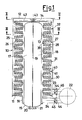
- the dyeing machine shown in Figures 1-3 consists essentially of a cylindrical, with its axis vertically arranged boiler 10, which has a flat bottom 11 and also a flat cover 12, which is fastened with the help of a bayonet lock, not shown.
- the tubular body 13 simultaneously represents a fleet displacement body and a heat exchanger.
- the tubular body 13 is divided on the inside by a vertical transverse wall 19 into two rooms 17, 18, which transverse wall extends below to the lower floor 15 and ends at a certain distance from the upper floor 14, close to the two rooms 17, 18 the upper end of the body 13 to communicate with each other.
- the lower floor 15 of the body 13 carries two connections, each with one of the rooms 17, 18 are connected and one of which serves for the entry and the other for the exit of a heating or cooling medium. Outside, the tubular body 13 is washed by the treatment liquor circulated within the boiler 10.
- a pump 22 is provided which is connected by means of the connections 23, 24 at the bottom to the cylindrical wall of the boiler 10 or to the cylindrical extension 16 of the bottom 11 thereof.
- spinable ring-shaped coil carriers are provided as material carriers, which do not per se belong to the invention and are therefore only described superficially.
- Each of these uniform elements is formed by an impermeable cylinder wall 25 which is arranged at regular, mutually spaced circles on superimposed parallel planes normal to the axis of the cylinder wall 25 Holes 26 is provided.
- a coil support 27 is radially fastened to each hole 26 within the wall 25, onto which a single coil 28 can be plugged and which has a shape corresponding to the coil (FIGS. 1 and 3 show this arrangement only schematically).
- each coil carrier 27 in a preferred embodiment essentially consists of a plastic body which is formed by a core 29, four radial ribs 33, a head part 34 and a tubular base part 35, the latter in a corresponding hole 26 of the cylinder wall 25 can be plugged in and fastened by means of a hexagon nut 36.
- the sleeve 37 of the coil 28, the wall of which is perforated throughout, is placed over the head part 34 (against which it seals) and the ribs 33 of the carrier 27 and engages in an annular groove 38 in the tubular base part 35.
- a handle 39 serves to to hold the coil 28 on the carrier 27.
- the liquid-tight placement of the uniform ring elements 30, 31, 32 is ensured in that the cylinder wall 25 of each element carries a profile ring 40 at the bottom (see FIG. 1) and a ring guide 41 at the top, in which the profile ring 40 of the element placed thereon can engage.
- An analog ring guide is provided on the boiler bottom 11, while an impermeable cover 42 is placed on top, which engages in the ring guide 41 of the uppermost element 32 by means of a profile ring and is fastened to the upper curved bottom 14 of the tubular body 13 by means of a threaded pin and wing nut 43.
- the tubular body 13 namely has a diameter such that it forms an annular space just sufficient for accommodating the material carriers with the cylindrical vessel wall.
- the treatment liquor completely fills the interior of the boiler, which has been left free by the tubular body 13 and the material carriers.
- the liquor flows around the entire wide surface of the tubular body 13 and thus experiences an effective heat exchange.
- the unitary elements 30, 31, 32 can be connected to one another, also using suitable means (not shown), so that they are handled as a unit can.
- the textile material to be treated is in the form of cross-wound bobbins, but other types of clothing, for example cylindrical bobbins, could also be provided.
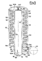
- FIG. 5 The embodiment of the machine shown in FIG. 5 is similar to that described so far and its parts, which correspond to those already mentioned, are identified by the same reference numerals, but increased by 100.
- a first difference lies in the design of the heat exchanger, which again comprises a tubular body 113, but which has no internal partition, while the inlet Lan 120 of the heat exchange medium with a comparison réellesrohrstutzen 120A is provided g, of a piece from the lower floor 115 of the body rises up.
- This solution is particularly suitable in the event that steam is used as the heating medium.
- the extension pipe socket 120A at the inlet 120 aims to introduce the steam into the pipe body 113 above the condensate sump forming at the bottom of the body.
- a hollow, closed base plate 146 is provided by ge A suitable shape is provided on which the lower unitary element 130 stands up in a liquid-tight manner and can optionally be coupled.
- the base plate 146 in turn rests in a liquid-tight manner on an annular support 147 which is formed at the upper end of a tube 148 which concentrically surrounds the lower part of the tube body 113 and in turn is arranged concentrically within the cylindrical projection 116 of the curved base 111A of the boiler 110.
- the tube 148 protrudes beyond the cylindrical extension 116 and forms gaps both with the latter and with the tube body 113, with which the connections 123 and 124 are connected.
- a perforated cylinder wall 149 is firmly connected to the shaped base plate 146, which is closed at the top by a cover 150 and is placed over the tubular body 113, from the cylindrical wall of which it remains at a short distance.
- the cover 142A placed on the upper unitary element 132 is also in the form of a hollow, closed displacer in order to fill the dead space formed by the curvature of the cover 112A of the boiler 110.
- the base plate 146 with the perforated cylinder wall 149 and with the cover 142A belong to the material carrier and can, of course after the loosening of the fastening wing nut 143, be handled together with the dimensional elements 130, 131, 132.
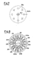
- FIGS. 6-8 show a further embodiment of the machine, the parts of which correspond to those of the machine according to FIG. 5 with the same reference numerals, but increasingly designated by 100.
- the tubular body 213 has the dual function of a fleet displacement body and a support for an outer coil 251, the lower and upper ends of which are connected to the inlet 220 and the outlet 221 of the heat exchange medium via lines running inside the tubular body 213 flat bottom 215A of the body 213 are attached.
- the heat exchange medium no longer flows through the tubular body 213, as in the previously described embodiments, but is passed through the coil 251, which is washed by the treatment liquor circulated by the boiler 210.
- unitary coil support elements 230A, 231A, 232A are double-walled instead of single-walled.
- the inside the coil support 227 carrying impermeable cylindrical wall 225 of each mass unitary element outside in ei - is nem certain distance from a second impermeable cylindrical wall 225A concentrically surrounded, forming with the first a gap 252, and with the cylindrical Wall of the boiler 210 an intermediate space 253.
- the cavity of the base plate 246A is on the one hand with the intermediate space 252 and on the other hand via a double ring support 247A with the intermediate space formed between the tube 248 and the lower part of the tubular body 213 and thus with the connection 224 .
- the space 253 communicates at the bottom with the space formed between the tube 248 and the cylindrical extension 216 of the curved bottom 211A of the boiler 210 and thus with the connection 223, while at the top it communicates with the space within the walls 225 of the unitary elements 230A, 231A , 232A is connected by openings 254, which are recessed in the cover 242A designed as a displacement body, which occupies the upper dead space under the domed cover 212A of the boiler 210.
- FIG. 9 The machine shown in FIG. 9 is similar to that of FIGS. 6-8 and its corresponding parts are provided with the same reference numerals, which are, however, increased by 100.
- tubular body 313 does not carry a separate coil, but rather a coil 351A, which is formed by a tube which is semicircular in cross section and is directly attached to the wall of the body, for example welded on.
- a coil 351A which is formed by a tube which is semicircular in cross section and is directly attached to the wall of the body, for example welded on.
- the operation of this heat exchanger is otherwise the same as that previously described.
- FIG. 9 Another difference is that the machine according to FIG. 9 is equipped with a conventional material carrier instead of a centrifugal material carrier that can be thrown.
- This conventional material carrier is well known in the art and is therefore only shown schematically and only described in broad outline. It consists of a hollow base plate 346A, on which vertical support rods 355 are attached on concentric circles and at mutual intervals, onto each of which a number of coils 328, each separated by an intermediate disk 356, can be attached in sequence. The row of coils on each rod 355 is held by a quick release 357 or the like.
- FIG. 10 is taken into consideration, it can be seen that the same criteria are also valid and applicable when the machine is used to treat textile goods with an unsalted liquor, which textile goods not in the form of spools of thread, but for example in the form of warp beams or wound fabrics.
- the machine also has a bowl 410 with a curved bottom 411A and a curved lid.
- the bottom has a cylindrical shoulder 416 in which a tube 448 is arranged, which at one end forms an annular support 447 for a base flange 446A which carries a perforated cylinder wall 449.
- the chain yarn or the wound fabric 460 is arranged between the base flange 446A and a head flange 442B.
- a tubular body 413 is arranged within the perforated cylinder wall 449 as a heat exchanger and liquor displacement body.
- the heat exchange 10 is a double-walled heat exchanger, a second closed tubular body 413A being arranged within the tubular body 413, which forms an intermediate space 417A with the first, in which the inlet and outlet connections 420, 421 for the Heat exchange means a transverse wall 419A is arranged.
- the heat exchange medium thus enters through the inlet 420 and, after flowing through the space 417A, can exit again through the outlet 421.
- the various embodiments of the machine according to the invention have in common the basic principle that the dead spaces within the boiler are reduced to a minimum, primarily thanks to the use of a special heat exchanger system with an elongated structure in the middle of the boiler and further thanks to the presence of additional float displacement bodies if a boiler with a domed bottom and lid has to be used instead of a flat bottom and lid.
Landscapes
- Engineering & Computer Science (AREA)
- Chemical & Material Sciences (AREA)
- Materials Engineering (AREA)
- Textile Engineering (AREA)
- Treatment Of Fiber Materials (AREA)
- Chemical Or Physical Treatment Of Fibers (AREA)
- Coloring (AREA)
Priority Applications (1)
| Application Number | Priority Date | Filing Date | Title |
|---|---|---|---|
| AT81200292T ATE11579T1 (de) | 1980-03-20 | 1981-03-14 | Maschine zum faerben oder bleichen von aufgewickeltem textilgut in kurzer flotte. |
Applications Claiming Priority (2)
| Application Number | Priority Date | Filing Date | Title |
|---|---|---|---|
| IT20792/80A IT1131007B (it) | 1980-03-20 | 1980-03-20 | Apparecchio per la tintura od il candeggio in bagno corto di materiali tessili,quali filati in rocche, subbi o simili,tessuti arrotolati od altri |
| IT2079280 | 1980-03-20 |
Publications (2)
| Publication Number | Publication Date |
|---|---|
| EP0036690A1 EP0036690A1 (de) | 1981-09-30 |
| EP0036690B1 true EP0036690B1 (de) | 1985-01-30 |
Family
ID=11172126
Family Applications (1)
| Application Number | Title | Priority Date | Filing Date |
|---|---|---|---|
| EP81200292A Expired EP0036690B1 (de) | 1980-03-20 | 1981-03-14 | Maschine zum Färben oder Bleichen von aufgewickeltem Textilgut in kurzer Flotte |
Country Status (5)
| Country | Link |
|---|---|
| EP (1) | EP0036690B1 (it) |
| AT (1) | ATE11579T1 (it) |
| DE (1) | DE3168569D1 (it) |
| ES (1) | ES267121Y (it) |
| IT (1) | IT1131007B (it) |
Families Citing this family (3)
| Publication number | Priority date | Publication date | Assignee | Title |
|---|---|---|---|---|
| IT1237582B (it) * | 1989-11-09 | 1993-06-08 | Luciano Casasola | Apparecchiatura a combustione sommersa per tingere i filati |
| GB2274660B (en) * | 1993-01-26 | 1996-01-31 | Falmer Investment Ltd | Dyeing vessels |
| JP4284670B2 (ja) | 2000-03-23 | 2009-06-24 | ミネベア株式会社 | 玉軸受及びその潤滑方法 |
Citations (6)
| Publication number | Priority date | Publication date | Assignee | Title |
|---|---|---|---|---|
| FR2028300A1 (it) * | 1969-01-14 | 1970-10-09 | Svensson Ludvig Ab | |
| DE2207670A1 (de) * | 1972-02-18 | 1973-08-30 | Brueckner Apparatebau Gmbh | Vorrichtung zur nassbehandlung von textilmaterial |
| FR2247571A1 (it) * | 1973-10-16 | 1975-05-09 | Bergholtz & Co Kb Niels | |
| FR2253865A1 (it) * | 1973-12-01 | 1975-07-04 | Thies Kg | |
| FR2258902A1 (en) * | 1974-01-28 | 1975-08-22 | Durand Maurice | Autoclave for dyeing textiles wound onto cylinder - includes centre body within cylinder to form annular passage through which dye flows |
| FR2326230A1 (fr) * | 1975-10-01 | 1977-04-29 | Barriquand | Perfectionnements apportes aux appareils autoclaves horizontaux pour la teinture et/ou le blanchiment matieres textiles |
Family Cites Families (1)
| Publication number | Priority date | Publication date | Assignee | Title |
|---|---|---|---|---|
| DE2451828A1 (de) * | 1974-10-31 | 1976-05-06 | Jagri Mach & Apparatebau | Faerbeanlage |
-
1980
- 1980-03-20 IT IT20792/80A patent/IT1131007B/it active
-
1981
- 1981-03-14 AT AT81200292T patent/ATE11579T1/de active
- 1981-03-14 DE DE8181200292T patent/DE3168569D1/de not_active Expired
- 1981-03-14 EP EP81200292A patent/EP0036690B1/de not_active Expired
- 1981-03-18 ES ES1981267121U patent/ES267121Y/es not_active Expired
Patent Citations (6)
| Publication number | Priority date | Publication date | Assignee | Title |
|---|---|---|---|---|
| FR2028300A1 (it) * | 1969-01-14 | 1970-10-09 | Svensson Ludvig Ab | |
| DE2207670A1 (de) * | 1972-02-18 | 1973-08-30 | Brueckner Apparatebau Gmbh | Vorrichtung zur nassbehandlung von textilmaterial |
| FR2247571A1 (it) * | 1973-10-16 | 1975-05-09 | Bergholtz & Co Kb Niels | |
| FR2253865A1 (it) * | 1973-12-01 | 1975-07-04 | Thies Kg | |
| FR2258902A1 (en) * | 1974-01-28 | 1975-08-22 | Durand Maurice | Autoclave for dyeing textiles wound onto cylinder - includes centre body within cylinder to form annular passage through which dye flows |
| FR2326230A1 (fr) * | 1975-10-01 | 1977-04-29 | Barriquand | Perfectionnements apportes aux appareils autoclaves horizontaux pour la teinture et/ou le blanchiment matieres textiles |
Also Published As
| Publication number | Publication date |
|---|---|
| ES267121U (es) | 1983-05-16 |
| EP0036690A1 (de) | 1981-09-30 |
| ATE11579T1 (de) | 1985-02-15 |
| DE3168569D1 (en) | 1985-03-14 |
| IT8020792A0 (it) | 1980-03-20 |
| IT1131007B (it) | 1986-06-18 |
| ES267121Y (es) | 1983-11-16 |
Similar Documents
| Publication | Publication Date | Title |
|---|---|---|
| DE2921618A1 (de) | Faerbevorrichtung | |
| DE69424625T2 (de) | Vorrichtung zum Nassbehandeln von Geweben | |
| DE69903355T2 (de) | Modulierbare entkeimungsvorrichtung mit einem schraubenförmigen durchlauf für verschlussteile für flaschen | |
| EP0036690B1 (de) | Maschine zum Färben oder Bleichen von aufgewickeltem Textilgut in kurzer Flotte | |
| DE608956C (de) | Vorrichtung zum Nassbehandeln von Fasergut im Wanderstapel | |
| WO2015086163A1 (de) | Zentrifugalfärbeapparat zur behandlung von gewickelten flächengebilden, insbesondere von textilbahnen mit flüssigkeiten | |
| DE3112246C2 (de) | Vorrichtung zum Behandeln von Materialien, wie z.B. Textilien, mit einer Behandlungsflüssigkeit | |
| DE2525871A1 (de) | Vorrichtung zum diskontinuierlichen nassbehandeln von textilgut | |
| EP0360086B1 (de) | Handtuchtrockner | |
| DE3636225C2 (de) | Vorrichtung zum Naßbehandeln von textilen Warenbahnen | |
| DE2443300A1 (de) | Verfahren zum lockern von waesche nach dem schleudergang in einer waschmaschine und vorrichtung zum durchfuehren dieses verfahrens | |
| EP0034390B1 (de) | Spulenträger für Färbe- und Bleichmaschinen | |
| DE68913362T2 (de) | Vorrichtung zum Färben bzw. Bleichen von Garnen oder dergleichen. | |
| DE2822328C2 (de) | Färbevorrichtung | |
| CH650294A5 (de) | Vorrichtung zur nassbehandlung, insbesondere zum faerben, von strangfoermigem textilgut. | |
| AT227219B (de) | Vorrichtung zum Färben von Stranggarn | |
| DE2644968C2 (it) | ||
| DE3104609C2 (de) | Vorrichtung zur Naßbehandlung von strangförmigem Textilgut | |
| DE4206954A1 (de) | Verfahren zur behandlung von textilen substraten in einem ueberkritischen fluid sowie vorrichtung zur durchfuehrung des verfahrens | |
| CH386370A (de) | Vorrichtung zum Färben von Stranggarn | |
| DE2717313B2 (de) | Verfahren und Vorrichtung zum Naßbehandeln von strangförmigem Textilgut | |
| DE2451829A1 (de) | Faerbeanlage | |
| DE2448385C3 (de) | Vorrichtung zum Naßbehandeln eines endlos umlaufenden, strangförmigen Textilguts | |
| DE857570C (de) | Kaefigtrommel zum Trocknen von laufenden Faeden od. dgl., insbesondere Kunstseidefaeden | |
| DE1958535C3 (de) | Vorrichtung zum Naßbehandeln, insbesondere Färben von Natur- oder Kunststoffgarnen oder -fasern |
Legal Events
| Date | Code | Title | Description |
|---|---|---|---|
| PUAI | Public reference made under article 153(3) epc to a published international application that has entered the european phase |
Free format text: ORIGINAL CODE: 0009012 |
|
| AK | Designated contracting states |
Designated state(s): AT BE CH DE FR GB LU NL SE |
|
| 17P | Request for examination filed |
Effective date: 19811116 |
|
| GRAA | (expected) grant |
Free format text: ORIGINAL CODE: 0009210 |
|
| AK | Designated contracting states |
Designated state(s): AT BE CH DE FR GB LI LU NL SE |
|
| REF | Corresponds to: |
Ref document number: 11579 Country of ref document: AT Date of ref document: 19850215 Kind code of ref document: T |
|
| REF | Corresponds to: |
Ref document number: 3168569 Country of ref document: DE Date of ref document: 19850314 |
|
| ET | Fr: translation filed | ||
| PLBE | No opposition filed within time limit |
Free format text: ORIGINAL CODE: 0009261 |
|
| STAA | Information on the status of an ep patent application or granted ep patent |
Free format text: STATUS: NO OPPOSITION FILED WITHIN TIME LIMIT |
|
| 26N | No opposition filed | ||
| EPTA | Lu: last paid annual fee | ||
| EAL | Se: european patent in force in sweden |
Ref document number: 81200292.1 |
|
| PGFP | Annual fee paid to national office [announced via postgrant information from national office to epo] |
Ref country code: FR Payment date: 19950228 Year of fee payment: 15 |
|
| PGFP | Annual fee paid to national office [announced via postgrant information from national office to epo] |
Ref country code: LU Payment date: 19950301 Year of fee payment: 15 |
|
| PGFP | Annual fee paid to national office [announced via postgrant information from national office to epo] |
Ref country code: GB Payment date: 19950306 Year of fee payment: 15 Ref country code: BE Payment date: 19950306 Year of fee payment: 15 |
|
| PGFP | Annual fee paid to national office [announced via postgrant information from national office to epo] |
Ref country code: SE Payment date: 19950316 Year of fee payment: 15 Ref country code: AT Payment date: 19950316 Year of fee payment: 15 |
|
| PGFP | Annual fee paid to national office [announced via postgrant information from national office to epo] |
Ref country code: DE Payment date: 19950327 Year of fee payment: 15 Ref country code: CH Payment date: 19950327 Year of fee payment: 15 |
|
| PGFP | Annual fee paid to national office [announced via postgrant information from national office to epo] |
Ref country code: NL Payment date: 19950331 Year of fee payment: 15 |
|
| PG25 | Lapsed in a contracting state [announced via postgrant information from national office to epo] |
Ref country code: LU Free format text: LAPSE BECAUSE OF NON-PAYMENT OF DUE FEES Effective date: 19960314 Ref country code: GB Effective date: 19960314 Ref country code: AT Effective date: 19960314 |
|
| PG25 | Lapsed in a contracting state [announced via postgrant information from national office to epo] |
Ref country code: SE Effective date: 19960315 |
|
| PG25 | Lapsed in a contracting state [announced via postgrant information from national office to epo] |
Ref country code: LI Effective date: 19960331 Ref country code: CH Effective date: 19960331 Ref country code: BE Effective date: 19960331 |
|
| BERE | Be: lapsed |
Owner name: RONCHI FRANCESCO Effective date: 19960331 |
|
| PG25 | Lapsed in a contracting state [announced via postgrant information from national office to epo] |
Ref country code: NL Effective date: 19961001 |
|
| GBPC | Gb: european patent ceased through non-payment of renewal fee |
Effective date: 19960314 |
|
| REG | Reference to a national code |
Ref country code: CH Ref legal event code: PL |
|
| PG25 | Lapsed in a contracting state [announced via postgrant information from national office to epo] |
Ref country code: FR Effective date: 19961129 |
|
| NLV4 | Nl: lapsed or anulled due to non-payment of the annual fee |
Effective date: 19961001 |
|
| PG25 | Lapsed in a contracting state [announced via postgrant information from national office to epo] |
Ref country code: DE Effective date: 19961203 |
|
| EUG | Se: european patent has lapsed |
Ref document number: 81200292.1 |
|
| REG | Reference to a national code |
Ref country code: FR Ref legal event code: ST |