EP0033136A2 - Zündverteiler mit eingebauter Zündspule - Google Patents
Zündverteiler mit eingebauter Zündspule Download PDFInfo
- Publication number
- EP0033136A2 EP0033136A2 EP81100449A EP81100449A EP0033136A2 EP 0033136 A2 EP0033136 A2 EP 0033136A2 EP 81100449 A EP81100449 A EP 81100449A EP 81100449 A EP81100449 A EP 81100449A EP 0033136 A2 EP0033136 A2 EP 0033136A2
- Authority
- EP
- European Patent Office
- Prior art keywords
- ignition coil
- distributor
- rotation
- generating means
- signal generating
- Prior art date
- Legal status (The legal status is an assumption and is not a legal conclusion. Google has not performed a legal analysis and makes no representation as to the accuracy of the status listed.)
- Granted
Links
Images


Classifications
-
- F—MECHANICAL ENGINEERING; LIGHTING; HEATING; WEAPONS; BLASTING
- F02—COMBUSTION ENGINES; HOT-GAS OR COMBUSTION-PRODUCT ENGINE PLANTS
- F02P—IGNITION, OTHER THAN COMPRESSION IGNITION, FOR INTERNAL-COMBUSTION ENGINES; TESTING OF IGNITION TIMING IN COMPRESSION-IGNITION ENGINES
- F02P7/00—Arrangements of distributors, circuit-makers or -breakers, e.g. of distributor and circuit-breaker combinations or pick-up devices
- F02P7/02—Arrangements of distributors, circuit-makers or -breakers, e.g. of distributor and circuit-breaker combinations or pick-up devices of distributors
- F02P7/021—Mechanical distributors
- F02P7/026—Distributors combined with other ignition devices, e.g. coils, fuel-injectors
Definitions
- This invention generally relates to a distributor assembly for use with an ignition system of an internal combustion engine of a motor vehicle or the like. More particularly, the present invention relates to a distributor assembly having an ignition coil therein.
- Ignition devices for internal combustion engines of vehicles are recently required to have a higher suitability in installing on a vehicle and a higher reliability in electrical connection between parts.
- the present invention is to provide, in response to the above-mentioned requirements, an ignition device of a single unit having an ignition distributor and an ignition coil.
- the invention aims, in combining an ignition coil, to prevent the ignition device from malfunctioning by preventing the leakage flux of the ignition coil from being an undesirable influence on a magnetism- sensitive rotation signal generating means (for instance, an electromagnetic pickup using a permanent magnet and a coil) which is built in the ignition distributor.
- a magnetism- sensitive rotation signal generating means for instance, an electromagnetic pickup using a permanent magnet and a coil
- the leakage flux from the ignition coil is apt to affect rotation signal generating means, such as an electromagnetic pick up, which is arranged to produce a triggering signal by detecting the rotation of the engine crakshaft where the triggering signal will be used to control the energization of the primary winding of the ignition coil.
- rotation signal generating means such as an electromagnetic pick up
- a noise voltage may be induced due to the leakage flux from the ignition coil resulting in false triggering of the ignition coil.
- the ignition system malfunctions, and thus proper ignition timing is deteriorated.
- the present invention has been achieved in order to remove the above-described disadvantage and drawback inherent to the conventional distributor assembly having an ignition coil therein.
- an object of the present invention to provide a new and useful distributor assembly having an ignition coil, in which malfunction, such as false triggering, due to the leakage flux from the ignition coil is effectively prevented.
- a feature of the present invention is to provide a distributor assembly having an ignition coil, in which the leakage flux from the ignition coil is effectively used to prevent undesirable influence of external noises.
- the ignition coil is arranged in such a manner that a plane perpendicular to the axis of the main magnetic flux generated by the energization of the primary winding is substantially parallel to the magnetic sensitive direction of a rotation signal generating means, and the axis is parallel to the rotary shaft of the distributor to which a signal rotor is attached where the signal rotor is arranged to cause the rotation signal generating means to emit an output signal which will be used to control the energization of the ignition coil, while the rotation signal generating means is arranged at a substantially midway point of an external magnetic path of a magnetic flux passing through the axis of the main magnetic flux within the core of the ignition coil.
- the ignition coil is arranged in such a manner that the axis of the main magnetic flux made by the energization of the primary winding is substantially parallel to the rotary shaft of the distributor, while a rotation signal generating means is arranged in such a position that the magnetic sensitive direction thereof intersects a radial line from the axis of the main magnetic flux of the ignition coil at an angle other than 90 degrees so that appearance of a leakage flux of the ignition coil acts on the rotation signal generating means, which is caused by the rotation of a signal rotor attached to the rotary shaft, and disappearance of the leakage flux acts on the rotation signal generating means reducing a decreasing flux in the rotation signal generating means, which is caused by the rotation of the signal rotor.
- the plane parallel to the magnetic sensitive direction of the pickup coil 21 does not necessarily have to be perpendicular to the main flux axis (A) of the ignition coil 4, for instance the angle therebetween may be 80 degrees or so, to obtain substantially the same result. It is also apparent that there is a possibility of obtaining a desirable effect without exactly arranging the pickup coil 21 at the midway point along the external magnetic path of the ignition coil 4.
- the rotation signal generating means is constructed rotor 1 rotates in synchronism with the engine crankshaft.
- An electromagnetic pickup 2 comprising a pickup coil 21 and a permanent magnet 22 is arranged to face the signal rotor 1, and an output signal is developed across the coil 21 of the pickup 2 by the variation of magnetic flux due to the rotation of the signal rotor 1.
- An ignition amplifier 3 controls the intermittent energization of a primary winding 41 of an ignition coil 4 by selectively applying a current from a battery 5 in accordance with the output signal of the electromagnetic pickup 2.
- the magnetic flux which passes through the pickup coil 21 varies so that an output signal voltage as shown by a solid line waveform in Fig. 2 (a) is developed across the pickup coil 21.
- the above-mentioned ignition amplifier 3 detects the waveform of this output signal on the basis of a constant detecting level V 0 , which is shown by a broken line, and controls in such a manner, for instance, when the signal voltage is greater than the detecting level V o , the primary winding 41 of the ignition coil 4 is energized, and on the other hand, when smaller, the same is deenergized.
- the current flowing through the primary winding 41 of the ignition coil 4 is controlled as shown in Fig. 2 (b).
- the ordinates respectively indicate voltage V and current i, while the abscissa indicate time t.
- the usual arrangement is such that the signal rotor 1 is attached to the rotary shaft of the distrubutor 6, while the electromagnetic pickup 2 is disposed in the housing of the distributor 6 to face the signal rotor 1 so as to be sensitive to the flux variation in the radial direction of the signal rotor 1.
- the ignition amplifier 3 is also arranged inside the distributor 6.
- the noise voltage is in proportion to the variation rate of the leakage flux of the ignition coil 4, and will be superimposed on the original output signal waveform of the electromagnetic pickup 2 caused by the signal rotor 1, and therefore, it is predicted with high possibility that undesirable influences are given to the ignition amplifier and therefore, to the operation of the entire system of the ingition device.
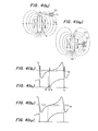
- Fig. 3 is a view showing the principle of a general ignition coil of closed magnetic path type, in which a pair of symmetric E-shapediron cores 43 and 43' are arranged to face each other, and primary and secondary windinc 41 and 42 are wound around the center leg portions 43a and 43'a thereof.
- an axis (A) of a main magnetic flux passes through the center leg portions 43a and 43'a when the primary winding 41 is energized.
- the ignition coil 4 is of closed magnetic path type, there exists a leakage flux from the magnetic circuit as is well known, and the leakage flux (a) is radially emitted from a substantial center of one E-shaped core 43, and then converges to a substantial center of the opposite E-shaped core 43'. Therefore, if the ignition coil 4 is arranged in a single unit with the electromagnetic pickup in a limited space of a distributor assembly, the coil of the electromagnetic pickup 2 is forced to be arranged in such a manner that the leakage flux (a) passes therethrough. As a result, it is a matter of course that a noise voltage is developed across the coil.of the electromagnetic pickup 2 owing to the leakage flux (a).
- Fig. 4 (a l ) shows the ignition coil 4 in cross-section taken along the axis (A) of the main magnetic flux generated by the current through the primary winding 41 thereof. It is assumed that the magnetic sensitive direction of the pickup coil 21 is the direction of an arrow (X), while the direction of the leakage flux (a) of the ignition coil 4 is the direction from the top end toward the bottom end of the main magnetic flux path.
- the leakage flux (a) which is radially emitted from the ignition coil 4 as shown by broken lines in Fig. 4 (a,), also passes in the same direction indicated by the arrow (Y) as the magnetic sinsitive direction of the pickup coil 21.
- a noise voltage due to the leakage flux (a) is superimposed on the pickup coil 21, and the waveform of the output signal voltage of the pickup coil 21 is as shown in Fig. 4 (b ), while the energization characteristic of the primary winding 41 of the ignition coil 4 is as shown in Fig. 4 ( c l ).
- the pickup coil 21 is arranged at a substantially midway point of an external magnetic path of the main magnetic flux passing through the axis (A) of the main magnetic flux within the core of the ignition coil 4, where the magnetic sensitive direction (X) thereof is arranged to be parallel to a plane which is perpendicular to the main magnetic flux axis (A) of the ignition coil 4.
- the leakage flux (a) passes through the pickup coil 21 in the arrow direction (Z) perpendicular to the magnetic sensitive direction thereof (X), so that no noise voltage can be superimposed on the output waveform of the pickup coil 21 as shown in Fig. 4 (b 2 ). Therefore, the waveform of the current flowing through the primary winding 41 of the ignition coil 4 is as shown in Fig. 4 (c 2 ), preventing the ignition amplifier 3 from malfunctioning.
- the leakage flux (a), which is shown by broken lines, from the ignition coil 4 passes through the coil 21 of the electromagnetic piciup 2 in a direction (Y) which is opposite to the above-mentioned passing direction (X) of the magnetic flux from the permanent magnet.
- the waveform of the output signal voltage of the pickup coil 21 is as shown in F ig. 5 (b 1 ), and the condition of energization of the primary winding of the ignition coil 4 is as shwon in Fig. 5 (c 1 ).
- the polarlity of the noise voltage in this case is opposite to the above-described case, and therefore, there will be no problem because the noise voltage is superimposed at the positive side of the output waveform of the pickup coil at the time of initialization (time t 4 ) of the energization of the ignition coil 4. Furthermore, when energization of the ignition coil is interrupted at time t 5 , a negative noise voltage is superimposed on the contrary, and thus no problem will occur.
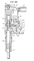
- Figs. 6A and 6P and Fig. 7 show an actual structure of the single-unit distibutor having an ignition coil as an embodiment of the present invention, in which the relationship shown in Fig. 4 (a 2 ) and/or Fig. 5 (a 2 ) has been actualized.
- Figs. 6A, 6B and 7, the same elements as in Figs. 1 to 4 are designated at like numerals.
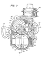
- a distributor body 100 comprises a distributor housing 110 and a cap 120.
- the housing 110 comprises a first cylinder portion 111 and a second cylinder portion 112 connected to top end of the former, where the diameter of the latter is greater than the latter.
- the cap 120 comprises a distributor cap portion 121 which covers the second cylinder portion 112, and an ignition coil cap portion 122 which covers an ignition coil described hereinlater, where the latter is arranged at one side of the former.
- the cap 120 is fastened by means of unshown screws to the top end of the second cylinder portion 112 of the housing 110.
- Between the housing 110 and the cap 120 interposed is a seal ring 130 for sealing the abutting portion therebetween.
- Flanges 113 are formed at two places on the housing 110, which flanges will be used to support the distributor to a supporting portion of an unshown internal combustion engine.
- a rotary shaft 140 is inserted in the first cylinder portion 111 of the housing 110, and the top end thereof is located at the inside of the second cvlinder portion 112. The top end of the same is telescopically engaged with a cylindrical distributor shaft 150, and the distributor shaft 150 and the rotary shaft 140 are linked by means of a well known centrifugal advance mechanism 160.
- the rotary shaft 140 comprises at its bottom end a gear 141 so as to be linked with the unshown internal combustion engine, and thus the rotary shaft 140 is rotated in proportion to the rotational speed of the internal combustion engine.
- the distributor shaft 150 rotates with an angle which has been advanced with respect to the rotary shaft 140 by a value corresponding to the rotational speed of the engine because of the operation of the centrifugal advance mechanism 160.
- a plate 170 is fixed by means of a screw 171 above the centrifugal advance mechanism 160.
- a signal rotor 1 is fixedly attached to the distributor shaft 150 above the sunporting member 172, and an electromagnetic pickup 2, which serves as a rotation signal generating means, is placed in the distributor body 100, facing to the signal rotor 1.
- the signal rotor 1 has projecteions la the number of which equals the number of the cylinders of the internal combustion engine; the number is four in this embodiment, and the rotation of the projections la will cause the magnetic flux passing through the electromagnetic pickup 2 to change.
- the electromagnetic pickup 2 has a structure such that the coil 21 thereof (see Fig.
- a coil portion 23 made of a mold of a synthetic resin, where the coil portion 23 is supported by a first bracket, and a permanent magnet 22 is interposed between the first bracket and a second bracket 25.
- the second bracket 25 is rotatably supported by means of a bearing 26 at the periphery of the supporting member 172, thereby the entire pickup 2 is also held.
- the magnetic flux from the permanent magnet 22 passes through a magnetic circuit (see a broken line in Fig. 6B) constructed of the second bracket 25, bearing 26, distrubutor shaft 150, signal rotor 1 and the first bracket 24, so as to pass through the pickup coil 21 in the coil portion 23.
- the pickup coil 21 has its magnetic sensitive direction in the radius direction of the signal rotor 1, and the megnetic flux varies as the signal rotor 1 rotates so that a rotation signal voltage will be developed across the pickup coil 21 as desclibed in the above.
- the above-mentioned second bracket 25 of the pickup 2 is provided with a pin 27, and a rod 181 of a well known vacuum advance mechanisum 180, which is mounted on the housing 11, is linked with the pin 27. Accordingly, the pickup 2 is rotated with respect to the supporting member 172 (and therefore the signal rotor 1) by the operation of the vacuum advance mechanism 180 which is operatively coupled to the intake manifold of the engine. It is well known that the ignition timing changes because of the rotation of the pickup 2 and also because of the above-mentioned rotation of the distributor shaft 150 (signal rotor 1) with respect to the rotary shaft 140.
- the ignition coil 4 has a structure such that a pair of iron cores of closed magnetic path type as shown in Fig. 3, and primary and secondary windings incorporated therein are all contained in a case 44 made of a synthetic resin, where the inside of the case 44 is filled with a mold made of a synthetic resin 45.
- a section of the second cylinder portion 112 of the housing 110 is cut off to install the ignition coil 4, where posts 114 are provided at both sides of the ignition coil 4.
- the ignition coil 4 is fixedly supported at the posts l14 by means of installing bolts 46 fitted in installing holes 431 of the iron core 43. Four installing bolts in total, namely two for each post 114, are used.
- the ignition coil 4 is fixed at one side of the second cylinder portion 112 of the housing 110 as described in the a ove, in such a manner that the main magnetic flux axi k (A) occuring on energization of the primary winding is parallel to the axis of the rotary shaft 140.
- the center of gravity of the entire distributor is lower than a portion of the distributor at which the distributor assembly is fixed to the engine, and thus it is advantageous in connection with vibrationproof characteristic.
- the positional relationship between the ignition coil 4 and the above-mentioned electromagnetic pickup 2 is selected to be the relation described with reference to Fig. 4 (a 2 ) and/or Fig.
- the electromagnetic pickup 2 is rotated about the signal rotor 1 by the operation of the vacuum advance mechanism 180 in order to control the ignition timing, and in this case it is a matter of course that the pickup 2 is rotated with the above-mentioned positional relationsnip represented by Fig. 4 ja2) and/or Fig. 5 (a 2 ) with respect to the ignitiol On coil 4.
- a flange 441 which meets the upper surface of the housing 110, and this flange 441 abuts against the coil cap portion 122 of the cap 120 via the above-mentioned seal ring 130. Accordingly, the ignition coil 4 is covered by the cap 120.
- the ignition amplifier 3 shown in Fig. 1 is fixed by means of suitable means such as unshown screws.
- the amplifier 3 has a structure such that electronic elements are arranged in a metallic case 31 which also serves as a radiator, and the amplifier 3 is covered by a case 32 made of a synthetic resin.
- the amplifier 3 is connected respectively to the pickup 2 and to the ignition coil 4 by leads 33 and 34.
- the lead connecting the amplifier 3 to the ignition coil 34 is supported by a clamp 442 which is integrally formed with the case 44 of the ignition coil 4, and thus care is taken not to interfere the signal rotor 1.
- Leads 35 and 47 from the amplifier 3 and the ignition coil 4 are drawn outside via a grommet 190 attached to the housing 110 so as to be connected to the battery 5 (see Fig. 1).
- a center electrode 200 At the top center of the disbributor cap 121 of the cap 120 disposed is one end of a center electrode 200, where a brush 202 biased by a spring 202 is also disposed.
- a distributor rotor 210 To the upper end of the above-mentioned distributor 150 attached is a distributor rotor 210, and a rotor electrode 211 is fixed to the upper surface of the distributor rotor 210.
- the brush 202 is in contact with the rotor electrode 211.
- the center electrode 200 extends to the ignition coil cap portion 122, and the other end is placed above the ignition coil 4, where a brush 204 biased by a spring 203 is also disposed.
- a high tension terminal 48 connected to the secondary winding is provided to the ignition'coil 4 so as to correspond to the brush 204, where a cylindrical tower portion 49 is integrally formed with the case 44 to surround the same.
- the brush 204 is in contact ⁇ with this high tension terminal 48.
- the high voltage from the ignition coil 4 is applied to the center electrode 200, and is led therethrough to the rotor electrode 211.
- the connection between the center electrode 200 and the ignition coil 4 is completed by simply placing the cap 120 on the housing 110.
- side electordes 220 are led to a tower portion 123 which projects toward the side of the cap 120.
- the rotor electrode 211 faces the side electrodes one after another by the rotation of the distributor rotor 210, distributing high voltage.
- the distributed high voltages are led to spark plugs 7 (see Fig. 1) which are connected via high tension codes connected to the tower portion 123.
- Fig. 1 shows a general ignition device or system to which the present invention is adapted.
- a signal rotor 1 having the same number of projections as the number of cylinders of an engine E is rotated by the engine E in proportion to the rotational speed thereof.
- the signal by using a Hall element utilizing Hall effect, or magnetic reluctance element, without being limited by the above example.
Landscapes
- Engineering & Computer Science (AREA)
- Chemical & Material Sciences (AREA)
- Combustion & Propulsion (AREA)
- Mechanical Engineering (AREA)
- General Engineering & Computer Science (AREA)
- Ignition Installations For Internal Combustion Engines (AREA)
Applications Claiming Priority (4)
| Application Number | Priority Date | Filing Date | Title |
|---|---|---|---|
| JP725680A JPS6018834B2 (ja) | 1980-01-23 | 1980-01-23 | 点火コイル一体型点火配電器 |
| JP725580A JPS56104162A (en) | 1980-01-23 | 1980-01-23 | Distributor integrated with ignition coil |
| JP7255/80 | 1980-01-23 | ||
| JP7256/80 | 1980-01-23 |
Publications (3)
| Publication Number | Publication Date |
|---|---|
| EP0033136A2 true EP0033136A2 (de) | 1981-08-05 |
| EP0033136A3 EP0033136A3 (en) | 1982-02-17 |
| EP0033136B1 EP0033136B1 (de) | 1984-07-25 |
Family
ID=26341525
Family Applications (1)
| Application Number | Title | Priority Date | Filing Date |
|---|---|---|---|
| EP81100449A Expired EP0033136B1 (de) | 1980-01-23 | 1981-01-22 | Zündverteiler mit eingebauter Zündspule |
Country Status (5)
| Country | Link |
|---|---|
| US (1) | US4365609A (de) |
| EP (1) | EP0033136B1 (de) |
| AU (1) | AU522547B2 (de) |
| CA (1) | CA1159102A (de) |
| DE (1) | DE3164930D1 (de) |
Cited By (1)
| Publication number | Priority date | Publication date | Assignee | Title |
|---|---|---|---|---|
| US4365609A (en) * | 1980-01-23 | 1982-12-28 | Nippondenso Co., Ltd. | Distributor assembly having an ignition coil therein |
Families Citing this family (10)
| Publication number | Priority date | Publication date | Assignee | Title |
|---|---|---|---|---|
| JPS5825580A (ja) * | 1981-08-07 | 1983-02-15 | Nippon Denso Co Ltd | 点火コイル一体型点火配電器を有する点火装置 |
| JPH0531267Y2 (de) * | 1987-11-09 | 1993-08-11 | ||
| JPH0663498B2 (ja) * | 1988-09-19 | 1994-08-22 | 株式会社日立製作所 | 内燃機関用配電器 |
| JPH0776546B2 (ja) * | 1988-10-12 | 1995-08-16 | 三菱電機株式会社 | 機関制御用信号発生装置 |
| US6752134B1 (en) | 2001-02-15 | 2004-06-22 | Pertronix, Inc. | Ignition arrangement |
| US6609507B2 (en) | 2001-08-20 | 2003-08-26 | Pertronix, Inc. | Second strike ignition system |
| AT504010B1 (de) * | 2006-05-12 | 2008-10-15 | Ge Jenbacher Gmbh & Co Ohg | Zündeinrichtung für eine brennkraftmaschine |
| FR2921433B1 (fr) * | 2007-09-25 | 2009-11-06 | Mann & Hummel Gmbh | Dispositif de mise en tourbillonnement et de melange de gaz d'echappement recycles dans la tubulure d'aspiration d'un moteur a combustion interne. |
| US20110132339A1 (en) * | 2009-12-04 | 2011-06-09 | Jerry Hoffmann | Multiple Coil Distributor and Method of Use Thereof |
| WO2021156365A1 (en) | 2020-02-06 | 2021-08-12 | Philip Morris Products S.A. | Electrically operated aerosol-generating device with means for detecting an airflow in the device |
Family Cites Families (10)
| Publication number | Priority date | Publication date | Assignee | Title |
|---|---|---|---|---|
| NL51885C (de) * | ||||
| US1277388A (en) * | 1918-03-06 | 1918-09-03 | Westinghouse Electric & Mfg Co | Ignition mechanism. |
| US3328614A (en) * | 1964-08-24 | 1967-06-27 | Gen Motors Corp | Breakerless ignition control unit |
| DE2038037C3 (de) * | 1970-07-31 | 1979-04-05 | Robert Bosch Gmbh, 7000 Stuttgart | Zündverteiler fur Brennkraftmaschinen mit Steuergenerator |
| US3888225A (en) * | 1973-09-26 | 1975-06-10 | Gen Motors Corp | Internal combustion engine ignition controller |
| GB1604129A (en) * | 1977-06-09 | 1981-12-02 | Ducellier & Cie | Magnetically controlled ignition distributor |
| US4129107A (en) * | 1977-08-22 | 1978-12-12 | General Motors Corporation | Magnetic pickup type ignition distributor |
| JPS54121912A (en) * | 1978-03-14 | 1979-09-21 | Fuji Electric Co Ltd | Rotary position signal generator |
| FR2432096A1 (fr) * | 1978-07-26 | 1980-02-22 | Abg Semca | Systeme d'allumage pour moteur a combustion interne |
| AU522547B2 (en) * | 1980-01-23 | 1982-06-10 | Nippondenso Co. Ltd. | Ignition coil in distributor assembly |
-
1981
- 1981-01-15 AU AU66244/81A patent/AU522547B2/en not_active Expired
- 1981-01-16 US US06/225,530 patent/US4365609A/en not_active Expired - Lifetime
- 1981-01-22 EP EP81100449A patent/EP0033136B1/de not_active Expired
- 1981-01-22 CA CA000369076A patent/CA1159102A/en not_active Expired
- 1981-01-22 DE DE8181100449T patent/DE3164930D1/de not_active Expired
Cited By (1)
| Publication number | Priority date | Publication date | Assignee | Title |
|---|---|---|---|---|
| US4365609A (en) * | 1980-01-23 | 1982-12-28 | Nippondenso Co., Ltd. | Distributor assembly having an ignition coil therein |
Also Published As
| Publication number | Publication date |
|---|---|
| CA1159102A (en) | 1983-12-20 |
| EP0033136A3 (en) | 1982-02-17 |
| US4365609A (en) | 1982-12-28 |
| DE3164930D1 (en) | 1984-08-30 |
| AU6624481A (en) | 1981-07-30 |
| AU522547B2 (en) | 1982-06-10 |
| EP0033136B1 (de) | 1984-07-25 |
Similar Documents
| Publication | Publication Date | Title |
|---|---|---|
| EP0033136A2 (de) | Zündverteiler mit eingebauter Zündspule | |
| US3955550A (en) | Flywheel magneto ignition device with capacitor-thyristor ignition combined with generator | |
| KR950007109Y1 (ko) | 홀효과(Hall effect)형 센서장치 | |
| US4527535A (en) | Ignition system including ignition distributor integrated with ignition coil | |
| JPS6237226B2 (de) | ||
| US4989574A (en) | Electromagnetic pickup | |
| JPH025101Y2 (de) | ||
| JPS6018834B2 (ja) | 点火コイル一体型点火配電器 | |
| JP2796289B2 (ja) | 内燃機関用点火コイル一体型配電器 | |
| JPH0132644B2 (de) | ||
| JPS6350671A (ja) | 内燃機関用点火コイル一体型配電器 | |
| JP2581307Y2 (ja) | パルサ付磁石発電機 | |
| JP2862760B2 (ja) | 点火コイル一体型配電器及び電磁ピックアップ | |
| JPS6134864Y2 (de) | ||
| JPH04116270A (ja) | 内燃機関用点火コイル一体形配電器 | |
| JPS6033350Y2 (ja) | 機関点火用信号発生装置 | |
| JPS6130150B2 (de) | ||
| HK1005750A1 (en) | Signal generator for an internal combustion engine | |
| JPS62199966A (ja) | 点火コイル一体形配電器 | |
| JPS609428Y2 (ja) | 機関信号発生装置 | |
| JPS6296774A (ja) | 内燃機関用配電器 | |
| JP2567899B2 (ja) | 内燃機関用回転信号検出装置 | |
| JPS62168966A (ja) | 内燃機関の点火配電器 | |
| JPS5943311A (ja) | 回転角度検出装置 | |
| JP2554587Y2 (ja) | 配電キャップ |
Legal Events
| Date | Code | Title | Description |
|---|---|---|---|
| PUAI | Public reference made under article 153(3) epc to a published international application that has entered the european phase |
Free format text: ORIGINAL CODE: 0009012 |
|
| AK | Designated contracting states |
Designated state(s): DE FR GB |
|
| PUAL | Search report despatched |
Free format text: ORIGINAL CODE: 0009013 |
|
| AK | Designated contracting states |
Designated state(s): DE FR GB |
|
| 17P | Request for examination filed |
Effective date: 19820226 |
|
| GRAA | (expected) grant |
Free format text: ORIGINAL CODE: 0009210 |
|
| AK | Designated contracting states |
Designated state(s): DE FR GB |
|
| REF | Corresponds to: |
Ref document number: 3164930 Country of ref document: DE Date of ref document: 19840830 |
|
| ET | Fr: translation filed | ||
| PLBE | No opposition filed within time limit |
Free format text: ORIGINAL CODE: 0009261 |
|
| STAA | Information on the status of an ep patent application or granted ep patent |
Free format text: STATUS: NO OPPOSITION FILED WITHIN TIME LIMIT |
|
| 26N | No opposition filed | ||
| REG | Reference to a national code |
Ref country code: GB Ref legal event code: 746 |
|
| REG | Reference to a national code |
Ref country code: FR Ref legal event code: DL |
|
| PGFP | Annual fee paid to national office [announced via postgrant information from national office to epo] |
Ref country code: DE Payment date: 19991231 Year of fee payment: 20 |
|
| PGFP | Annual fee paid to national office [announced via postgrant information from national office to epo] |
Ref country code: FR Payment date: 20000112 Year of fee payment: 20 |
|
| PGFP | Annual fee paid to national office [announced via postgrant information from national office to epo] |
Ref country code: GB Payment date: 20000119 Year of fee payment: 20 |
|
| PG25 | Lapsed in a contracting state [announced via postgrant information from national office to epo] |
Ref country code: GB Free format text: LAPSE BECAUSE OF EXPIRATION OF PROTECTION Effective date: 20010121 |
|
| REG | Reference to a national code |
Ref country code: GB Ref legal event code: PE20 Effective date: 20010121 |