EP0026272B1 - Einrichtung für die Auspressung von Garnsträhnen und diesbezügliches Verfahren - Google Patents
Einrichtung für die Auspressung von Garnsträhnen und diesbezügliches Verfahren Download PDFInfo
- Publication number
- EP0026272B1 EP0026272B1 EP80103839A EP80103839A EP0026272B1 EP 0026272 B1 EP0026272 B1 EP 0026272B1 EP 80103839 A EP80103839 A EP 80103839A EP 80103839 A EP80103839 A EP 80103839A EP 0026272 B1 EP0026272 B1 EP 0026272B1
- Authority
- EP
- European Patent Office
- Prior art keywords
- pliers
- hanks
- sticks
- chain
- plant according
- Prior art date
- Legal status (The legal status is an assumption and is not a legal conclusion. Google has not performed a legal analysis and makes no representation as to the accuracy of the status listed.)
- Expired
Links
Images


Classifications
-
- F—MECHANICAL ENGINEERING; LIGHTING; HEATING; WEAPONS; BLASTING
- F26—DRYING
- F26B—DRYING SOLID MATERIALS OR OBJECTS BY REMOVING LIQUID THEREFROM
- F26B15/00—Machines or apparatus for drying objects with progressive movement; Machines or apparatus with progressive movement for drying batches of material in compact form
- F26B15/10—Machines or apparatus for drying objects with progressive movement; Machines or apparatus with progressive movement for drying batches of material in compact form with movement in a path composed of one or more straight lines, e.g. compound, the movement being in alternate horizontal and vertical directions
- F26B15/12—Machines or apparatus for drying objects with progressive movement; Machines or apparatus with progressive movement for drying batches of material in compact form with movement in a path composed of one or more straight lines, e.g. compound, the movement being in alternate horizontal and vertical directions the lines being all horizontal or slightly inclined
- F26B15/122—Machines or apparatus for drying objects with progressive movement; Machines or apparatus with progressive movement for drying batches of material in compact form with movement in a path composed of one or more straight lines, e.g. compound, the movement being in alternate horizontal and vertical directions the lines being all horizontal or slightly inclined the objects or batches of material being carried by transversely moving rollers or rods which may rotate
- F26B15/124—Machines or apparatus for drying objects with progressive movement; Machines or apparatus with progressive movement for drying batches of material in compact form with movement in a path composed of one or more straight lines, e.g. compound, the movement being in alternate horizontal and vertical directions the lines being all horizontal or slightly inclined the objects or batches of material being carried by transversely moving rollers or rods which may rotate the objects being yarn hanks
-
- D—TEXTILES; PAPER
- D06—TREATMENT OF TEXTILES OR THE LIKE; LAUNDERING; FLEXIBLE MATERIALS NOT OTHERWISE PROVIDED FOR
- D06B—TREATING TEXTILE MATERIALS USING LIQUIDS, GASES OR VAPOURS
- D06B15/00—Removing liquids, gases or vapours from textile materials in association with treatment of the materials by liquids, gases or vapours
- D06B15/02—Removing liquids, gases or vapours from textile materials in association with treatment of the materials by liquids, gases or vapours by squeezing rollers
-
- D—TEXTILES; PAPER
- D06—TREATMENT OF TEXTILES OR THE LIKE; LAUNDERING; FLEXIBLE MATERIALS NOT OTHERWISE PROVIDED FOR
- D06B—TREATING TEXTILE MATERIALS USING LIQUIDS, GASES OR VAPOURS
- D06B3/00—Passing of textile materials through liquids, gases or vapours to effect treatment, e.g. washing, dyeing, bleaching, sizing, impregnating
- D06B3/04—Passing of textile materials through liquids, gases or vapours to effect treatment, e.g. washing, dyeing, bleaching, sizing, impregnating of yarns, threads or filaments
- D06B3/08—Passing of textile materials through liquids, gases or vapours to effect treatment, e.g. washing, dyeing, bleaching, sizing, impregnating of yarns, threads or filaments as hanks
-
- F—MECHANICAL ENGINEERING; LIGHTING; HEATING; WEAPONS; BLASTING
- F26—DRYING
- F26B—DRYING SOLID MATERIALS OR OBJECTS BY REMOVING LIQUID THEREFROM
- F26B5/00—Drying solid materials or objects by processes not involving the application of heat
- F26B5/14—Drying solid materials or objects by processes not involving the application of heat by applying pressure, e.g. wringing; by brushing; by wiping
Definitions
- the invention relates to a system or plant for the removal of liquid from skein or hank yarns, wherein the skeins or hanks are carried on sticks, and it also relates to a process for such a plant.
- the yarn hanks that have been subjected to a treatment are arranged in cabinets (dyeing cabinets) or transport trucks, and are carried and stretched between two sticks inserted therein.
- a treatment in which they have been wetted to some extent, such as for example dyeing
- cabinets diseing cabinets
- transport trucks In order to supply such hanks to further treatments, at present the common practice is to manually take each pair of sticks from the dyeing cabinet or truck, then removing one stick of said pair and placing the other stick with the suspended hanks on a supply chute of a squeezing device.
- a pair of pliers of the squeezer grip each stick (with the suspended hanks), moving and locating it with the ends in supporting cups on a pair of slides of the squeezer, which provide for lowering the stick along with the hanks in the space or gap between a pair of spaced apart squeezing rollers, of which one is a driven roller and the other is an idle roller; then the squeezing rollers are moved near each other and the hanks therebetween are lifted (which causes the wringing or squeezing thereof) and then moved with the stick on an unloading chute by means of a further pair of pliers.
- the hanks are still manually gripped, withdrawn from the stick and generally inserted on the skein holder or hank carrier supports of a supply chain in a drier.
- French patent n. 2.137.917 describes a plant or device for squeezing hank yarns, in which the hanks are carried on sticks; the plant comprises a chain feeding device for the hanks, and a squeezing unit for said hanks; the chain device performs the feeding of hanks to the squeezing and withdrawal of hanks from the same.
- the hanks are carried on the chains through the squeezing supported on only one stick, in particular the upper or top stick of the two sticks which carry the hanks through a dyeing treatment upstream of the squeezing.
- This plant has an inconvenience that the hanks, downstream of the squeezing, are suspended from only one stick, and can not be spread apart; this prevents their transfer by machine to other mechanical conveyor means; and obliges the worker to intervene for the transfer downstream of the conveyor chains.
- the aim was proposed of mechanizing as far as possible the squeezing and transfer operation for the hanks.
- the aim was also proposed of providing a universal type of squeezing system or plant suitable for any existing plant for water removal from yarns operating with sticks of preset length.
- the process of the invention for transferring yarn hanks through a squeezing plant, said hanks entering said plant being extended between two hank-holding sticks inserted therein comprises the steps of: bringing both the hank-holding sticks adjacent to each other; moving both the adjacent sticks with the suspended hanks through the plant; spreading the sticks away from each other thereby widening out the hanks; withdrawing the hanks from the spread sticks, while removing said sticks.
- the conveyor-feeder device comprises a chain conveyor, in which two spaced apart chains stepwise intermittently move parallel to each other; both of the chains are made with plates provided with notches or cutouts of such a depth and width that two sticks at overlapped relationship can be received; between the chains there being a free space sufficient to accommodate the hanks hanging down from the sticks.
- a squeezing device comprises at least one pair, but preferably two pairs of stick gripping pliers (of which one pair of inlet pliers and one pair of outlet pliers); the inlet pliers take up the sticks as coupled by the feeder and place the stick ends in cups carried on a pair of vertically movable slides of the squeezer to lower the hanks between squeezing rollers, of which one is generally a driven roller and the other is an idle roller.
- the outlet pliers withdraw'the sticks from the cups, placing them on the unloading conveyor.
- the pliers jaws and cups are of a configuration and size for receiving two sticks at parallel overlapped relationship; according to a further feature of this invention, the operation is given to the driven roller by a free-wheel device in order to avoid the "blow" between the squeezing rollers when the hank is removed from the space therebetween.
- the squeezer unloading conveyor comprises a chain conveyor, wherein two chains are sufficiently spaced apart from each other that the hanks hang therebetween and parallel intermittently move; peculiarly, each chain alternately has a plate with a notch or cutout of sufficient area to receive only one stick and one or more plates free of notches or cutouts.
- a chain conveyor cooperates with a guiding and clearing device downstream of the squeezer outlet pliers to move the two coupled sticks of eac.h hank group away from each other, so as to support the hanks kept at spread apart condition by the pair of spaced apart sticks.
- a plant according to the invention also comprises a pliers transfer device apt to withdraw by two pairs of pliers the two spread apart sticks carrying the hanks for raising thereof from the unloading chains and withdrawal thereof by another apparatus, such as a spreadable rod apparatus for yarn transfer; examples of such apparatuses are disclosed in various copending applications of the same applicant.
- the whole system is so implemented as to be readily adapted to any stick size.
- the capability of adaptation to the stick lengths is achieved by mounting the members designed to engage the stick ends (that is, the chains for the chain conveyors; the hook supports for the squeezer and the transfer device) on frames carried on sliding bars transversely of the yarn hank travel, and by arranging known adjusting means such as, for example, screw and female thread assemblies controlled by a handwheel or other known means.
- the advantages achieved by this invention essentially consist of a reduction in personnel for operations with resulting lower operating costs; in a reduction of yarn entangling with resulting lower winding off costs, and in a high flexibility of the plant.
- FIG. 1 a brief explanation will now be given of the novel process and plant allowing the automatic movement of yarn hanks (shown at 1) on sticks (shown at 2), a squeezing operation and still automatically supply of the hanks to any known further transport means.
- reference numeral 11 denotes a supply conveyor or feeder
- 12 the squeezer unit
- 13 an unloading conveyor for the squeezer
- 14 a hank transfer device.
- the arrows show the movement direction for the hanks.
- the device shown at 15 of Fig. 2 may be any rectilinearly movable or rotating spreadable rod hank transfer device; suitable devices are the subject of various copending applications of the same applicant.
- a plant as above outlined is intended to be mounted downstream of a yarn dyeing plant, or other plant, after which the removal of liquid from the hank yarns is required.
- the hanks are carried at extended or stretched condition between two sticks 2 inserted therein.
- the novel process of the invention eliminates the operation of removing one of the two sticks, but provides that said two sticks 2 are moved near each other and concurrently support said hank 1 throughout the squeezing step, then providing at the outlet from the squeezing zone for use of the two sticks to widen or spread out said hanks to a sufficient extent to allow for the insertion of supporting rods for hank withdrawal.
- the supply device for the squeezer unit 12 is a chain device, as shown in Figs. 3, 4, 5, 6 and 7.
- a chain device comprises two chains 21 and 22 (which for the sake of simplicity are outlined by dash-dot line in Figs. 4 and 5) extending along parallel paths, each of which between two respective gear wheels 24 and 25 for chain 21 and 26 and 27 for chain 22.
- Gear wheels 24 and 26 perform a driving function for the respective chains.
- only one of said two gear wheels 24 or 26 is intermittently driven from any type of drive unit (not shown), preferably through a free-wheel device (not shown, as well known to those skilled in the art).
- connection between said two gear wheels 24 and 26 is provided by an intermediate shaft 32 carrying at the ends gear wheels 31 and 33 for the connection with further gear wheels 29 and 34, of which gear wheel 34 is integral with shaft 35 of gear wheel 26, and gear wheel 29 is integral with shaft 28 of gear wheel 24.
- said intermediate shaft is over and out of the chain path in order not to interfere with the hanks being conveyed.
- the gear wheels 24, 25, 26 and 27 of the chains are mounted within bearings 38 integral with movable bars 40 and 41.
- movable bars 40 and 41 Through bushing supports 42, 43, 44 and respectively 45, the latter are carried and can slide on a pair of guides 47 and 48 which are transversely arranged of the chains.
- these guides 47 and 48 are carried on upstanding frames 49 and 50, on which said intermediate shaft 32 is also rotably mounted.
- the displacement of said bars 40 and 41 on the guides is provided by any suitable means such as, for example, by a screw and female thread device shown at 51 and 52.
- a position at which said gear wheels 24, 25, 26 and 27 are shown near one another is shown by hatching on Fig. 5.
- the above mentioned chains 21 and 22 comprise, as shown on Figs. 6 and 7, plate elements 54 which are secured on chain elements 54', the latter being hinge interconnected by an intervening roller 55.
- each of such plate elements comprise a plate 56 welded on a base 56' of any shape and provided with a notch or cutout 57 of sufficient dimensions to accommodate two sticks 2 at overlapped position, as shown in Figs. 6 and 7.
- These notches or cutouts 57 are narrower than the stick heads 2', thereby being allowed to slide out of the respective plate.
- a metal strap 58 transversely extended from plate 56 may be provided for possible bearing of said heads.
- roller squeezer unit shown in Fig. 3 (partly schematically in this figure) and in Figs. 8, 9, 10, 11 and 12 will now be described.
- This squeezer unit conventionally comprises a pliers holding frame 60 which is horizontally movable along sliding guides 61 by means, for example, of a cylinder-piston assembly 61'.
- a frame 60 carries four vertical sliding rods 62, through which a carriage 65 can be lifted and lowered by a cylinder-piston assembly 64, and this carriage 65 has horizontal sliding rods (shown on Fig. 9) 66, 66 transverse of guides 61.
- two pliers holding heads 68, 68 can slide on the above mentioned horizontal sliding rods 66, 66, the approaching or removing movement for these heads 68, 68 being controlled by a worm screw device or assembly 69.
- a worm screw device or assembly 69 In Fig.
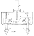
- each head carries two pliers and relative control cylinder-piston units or assemblies.
- Fig. 10 there are shown only one head 68, the relative pliers indicated at 70 and 71, and the control cylinder-piston units 72 and 73 therefore.
- Each of the pliers downwardly extend and upon adjustment of the distance or spacing are movable within a corresponding slot 74 provided in said box-like carriage 65.
- Each of the pliers for example pliers 70 of Fig. 8, comprise a body 76, having a pair of jaws 77, 78 pivoted thereon at 77' and 78', respectively.
- Jaw noses or ends are received in respective recesses or cavities in a slider 81 sliding in the body upon control of the respective cylinder-piston assembly or unit 72.
- the movement of said slider 81 relative to body 76 causes the opening and closing of the jaws.
- said jaws 77 and 78 are shown by full line at closed or approached position and by dashed line at removed or open position.
- Such jaws are of a particular shape with and elongated portion forming a cavity or recess 83 for receiving two overlapped sticks, 2, 2.
- the pliers can be moved as a unitary assembly in horizontal sliding direction, and can be lifted and lowered.
- the two pliers closer to the feeder comprise the inlet pair
- the two pliers closer to the unloading device comprise the outlet pair.
- the squeezer unit (Fig. 3) comprises a squeezing roller 85 at fixed position, which roller rotates in the direction as shown by the arrow, and an idle squeezing roller 86, movable between the position shown by full line in Fig. 3 and that shown by dashed line, under the control of the cylinder-piston unit or assembly 88.
- the movement to roller 85 is given by any type of free-wheel device in order to avoid any impact between the rollers, due to the difference in peripheral speed between said rollers, when the hank is extracted or removed.
- a hank between said rollers 85 and 86 is conventionally provided by a pair of opposite slides 90 (of which only one is shown in Fig. 3), which slides are provided with supports or bearing cups for the ends of sticks 2.
- a cylinder-piston unit or assembly 93 each of said slides are vertically slidable along guides 91 and 92.
- said two slides 90 are interconnected by a connection 94.
- the supports or cups (such as, for example, cup 96 shown in Figs. 11 and 12 on enlarged scale relative to Fig. 3) are of a sufficient size to receive the overlapped heads of two sticks 2, while cups of different dimensions (as shown by full line and dashed line in Figs. 11 and 12) are provided as interchangeable on said slides 90 for adaptation to sticks of different lengths.
- An unloading device comprises two timingly movable, parallel chain members. Such members are carried on bars (like bars 40 and 41 for the feeder) movable on transverse guides so as to be moved near and away from each other for adaptation to various lengths of the sticks. Up to this point, the assembling is similar to that of the chain feeder, and accordingly has not been shown on the drawings and will not be described in detail. Instead, the different features will be described.
- Each of the unloading device chains which for example will be denoted by 100, comprise plate elements secured on chain elements which are hinged to one another by small rollers 110. These plate elements are generally of two types denoted, for example, at 101 and 102.
- Element 101 has an upstanding plate welded on a base 101' with a recess or cavity 103 for receiving only one stick 2 (in Fig. 15 the stick is shown cutaway in the recess or cavity).
- this element 101 which is also shown in the upper half of Fig. 16, has a metal strap 104, projecting and underlying the stick head.
- the element 102 which is also shown in the lower half of Fig. 16, is avoid of recess or cavity and has a continuous surface 102a at the same level as the upper surface 101 a of element 101.
- a continuous surface comprises a bentover edge 106.
- the above mentioned chains 100 comprise elements 101 and 102.
- said elements 101 and 102 are alternated, that is to say that one element 101 is followed by one element 102 but, depending on the width to be given to the spread apart hanks, one element 101 and two or more elements 102 can be arranged; however, said elements 102 could be also omitted.
- Chains 100 are intermittently forwardly moved by a step or pitch which is four or more times than the chain pitch, or equal to the distance or spacing between each first and third cavities.
- the forward movement is controlled in any desired manner, preferably by a system comprising a rack 111 and gear wheel 112 (Fig. 15), in which said rack is driven by a cylinder-piston unit 111' and the gear wheel is connected to the driving gear wheel 113 for the chain, preferably by means of a freewheel system.
- Fig. 16 shows a shaft 114 for a gear wheel 113. This shaft is supported on bearings 115 and carries the gear wheel 112 as mounted, the freewheel device and intermediate gear wheel 116 for the drive to the other chain.
- a bearing plane 117 for the chain is also shown in Fig. 16.
- a cam separator 120 (Figs. 3, 13 and 14) is secured on the movable bars at fixed position, such a cam separator comprising two side plates 121 and 122 and a bottom plate 123, which plates are of lead-in configuration and adjustable in place for the setting up of the system.
- Such plates or cams 121, 122 and 123 retain a top stick 2, whereas the bottom stick, as received within a recess or cavity 103 of a chain element, is forward moved as the chain forward moves, until a new free recess or cavity 103 is encountered, into which the retained stick is allowed to fall down.
- the above mentioned plate 122 is retained in place by a calibrated spring in order to avoid jam- mings should an overlapped stick remain at restrained condition.
- a translating apparatus or transfer device providing for translating or transferring the skeins or hanks to another conveyor apparatus, and removing the sticks.
- Such a translating apparatus has been shown at 14 of Figs. 1.
- This apparatus comprises a supporting frame, denoted as a whole at 130, and which will not be further described as it may vary depending on the system arrangement.
- Said frame 130 carries two horizontal sliding guides, extending for a length on the chain unloading device and being substantially parallel thereto, such guides having been denoted by 131 and 132 in Fig. 18.
- a frame, denoted as a whole at 133 can slide on said guides 131 and 132, and substantially comprises two transverse sliding bars, which are denoted at 134 and 135.
- Two pliers holding heads 138 and 140 respectively, are movable along said sliding bars 134 and 135 for a spacing adjustment.
- the adjustment of the interspacing between said heads 138 and 140 is effected by a screw 141, the latter being controlled by a handwheel 142.
- This pliers holder head 138 comprises a block 143, at the ends of which two seats 134' and 135' are formed for sliding on bars 134 and 135, whereas a female threaded opening 141' for the adjusting screw 141 is shown centrally of the block.
- This block 143 carries sliding bearings 168 for two tubular or hollow elongated elements 146 and 147, respectively, each of which having sliding therein a rod connected to the piston of a cylinder-piston unit or assembly.
- the pliers 158 and 161 of head 138 which have been just described, will be for convenience hereinafter referred to as "front" pliers, which however should not be understood as a limitation to the invention.
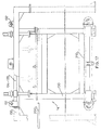
- the pliers of head 140, or rear pliers comprise the same elements as those for head 138, and additionally comprise a supporting plate rearwardly connected thereto, as shown in Fig. 20.
- Fig. 20 shows two "rear” pliers 170 and 171, or pliers for head 140, the respective tubular elements 172 and 173 (broken away) integral with the lower plate 174, the two bodies of the pliers shown at 176 and 177, respectively, and the jaws of the pliers shown at 179 and 180 (only the jaws at the right are shown).
- Plate 174 has secured thereto the supports denoted at 182 and 183, respectively, essentially comprising a plate 182' and 183', respectively, substantially arranged over the cavity forming the jaws of the pliers for receiving the sticks 2.
- the position of said plates 182 and 183 is such that, when a stick 2 is received and retained between the jaws, its head 2', by colliding against the respective plate 182', 183', enables the stick to be retained at substantially horizontal position even without the aid of the other pair of pliers.
- Said cylinder-piston units 93 operate to lift at a preset rate said slides 90 with the suspended hank 1 to remove it from the squeezing rollers 86 and 85.
- the interposition of the freewheel device in the control or drive for roller 85 avoids the occurrence of the so-called blow between said rollers 86 and 85, when a hank is missing therebetween, as it would occur in the prior art devices due to the difference in peripheral speed of the two rollers.
- the roller 86 Upon completion of the squeezing operation, the roller 86 is conventionally moved away. Now and still automatically, the squeezer frame 60 is restored to the condition shown by dashed line in Fig. 3, whereby the pair of outlet pliers shown at the right side of Fig.
- the second hank carrying stick falls down into said cavities and the hanks are suspended between two sticks at removed condition, that is are conveyed by the unloading device at a widened or spread out condition.
- the movements for the chain feeder, squeezer and unloading device are coordinated to allow said operation in any manner in the range of those skilled in the art.
- the movement of the translating device 14 is also coordinated with the above mentioned movements.
- the spacing between the "front" pliers and “rear” pliers of the translating device is preset at the plant installation in accordance with the spacing between the plates provided with cavities of the chain unloading device.
- the pliers of the translating device simultaneously grip, at the respective ends, the two spaced apart sticks, the latter being lifted and conveyed parallel to themselves.
- the amount of this transportation may be varied depending on the requirements of each specific system or plant.
- the translating device would supply the hanks on two rods, denoted at 200 of Fig. 17, of a spreadable rod transferring device, as disclosed in several copending applications of the same applicant.
- Such rods 200 are forward moved under the removed sticks 2 held by the pliers; and move away from one another, so as to support the hanks. Then, the front pliers (at the left side of Fig. 17) are opened and lifted, so that said rods 200 can be retracted to remove or unthread the hanks from sticks 2. At this stage, sticks 2 remain suspended, only carried by the pliers indicated as rear pliers 170 and 171 in Fig. 20.
- these last mentioned pliers Upon removal of the hanks, these last mentioned pliers also open so that the sticks can fall down on a suitable collection device, such as a carriage or a belt denoted at 210 of Fig. 17.
Claims (21)
Priority Applications (1)
| Application Number | Priority Date | Filing Date | Title |
|---|---|---|---|
| AT80103839T ATE10759T1 (de) | 1979-09-28 | 1980-07-05 | Einrichtung fuer die auspressung von garnstraehnen und diesbezuegliches verfahren. |
Applications Claiming Priority (2)
| Application Number | Priority Date | Filing Date | Title |
|---|---|---|---|
| IT2612779 | 1979-09-28 | ||
| IT26127/79A IT1123373B (it) | 1979-09-28 | 1979-09-28 | Impianto di spremitura di matasse,automatico e adattabile e diverse dimensioni di bastoni portamatasse;procedimento relativo |
Publications (2)
| Publication Number | Publication Date |
|---|---|
| EP0026272A1 EP0026272A1 (de) | 1981-04-08 |
| EP0026272B1 true EP0026272B1 (de) | 1984-12-12 |
Family
ID=11218695
Family Applications (1)
| Application Number | Title | Priority Date | Filing Date |
|---|---|---|---|
| EP80103839A Expired EP0026272B1 (de) | 1979-09-28 | 1980-07-05 | Einrichtung für die Auspressung von Garnsträhnen und diesbezügliches Verfahren |
Country Status (8)
| Country | Link |
|---|---|
| US (1) | US4374471A (de) |
| EP (1) | EP0026272B1 (de) |
| JP (1) | JPS601426B2 (de) |
| AT (1) | ATE10759T1 (de) |
| CA (1) | CA1174838A (de) |
| DE (1) | DE3069790D1 (de) |
| ES (1) | ES493863A0 (de) |
| IT (1) | IT1123373B (de) |
Families Citing this family (9)
| Publication number | Priority date | Publication date | Assignee | Title |
|---|---|---|---|---|
| WO1989000621A1 (en) * | 1987-07-13 | 1989-01-26 | Mario Scatizzi | Automatic machine for loading or unloading skeins |
| DE9312877U1 (de) | 1993-08-27 | 1993-10-28 | Schulte Strathaus Kg F E | Abstreiferleiste für Bandabstreifer zum Reinigen von Gurtbändern |
| CN1048300C (zh) * | 1994-01-14 | 2000-01-12 | 周春华 | 绞纱式浆染联合机 |
| JP6001845B2 (ja) * | 2011-11-30 | 2016-10-05 | 株式会社アマダホールディングス | 製品保管方法,製品保管装置,加工システム,及び被保管製品の製造方法 |
| IT201700014304A1 (it) * | 2017-02-09 | 2018-08-09 | Marcello Galvanin | Dispositivo di apertura e rotazione di matasse di filato umide |
| CN109097932B (zh) * | 2018-10-31 | 2020-10-30 | 浙江富兴服装有限公司 | 一种节能环保的染色机出料装置 |
| CN109338648B (zh) * | 2018-11-15 | 2021-12-07 | 青海瑞丝丝业有限公司 | 一种便于调节的针纺织品整烫台 |
| CN109436687B (zh) * | 2018-12-24 | 2024-02-23 | 蓬莱京鲁渔业有限公司 | 一种双桥式米饼机传动机构 |
| CN114165992A (zh) * | 2021-11-15 | 2022-03-11 | 无锡夏利达漂染有限公司 | 一种高效均匀的筒子纱节能射频烘干机 |
Family Cites Families (9)
| Publication number | Priority date | Publication date | Assignee | Title |
|---|---|---|---|---|
| US610781A (en) * | 1898-09-13 | Oooooooooooooooooooo | ||
| GB129532A (en) * | 1918-10-04 | 1919-07-17 | Louis Grimond Macintyre | A Machine for Dyeing, Bleaching, Washing and the like, Yarn and the like in Hank. |
| US1861600A (en) * | 1930-05-27 | 1932-06-07 | Burt S Harrison | Conveying system |
| GB678252A (en) * | 1949-11-23 | 1952-08-27 | Johann Fleissner | Improvements in drying devices for hank yarn |
| US2965214A (en) * | 1956-06-05 | 1960-12-20 | Buehler Ag Geb | Hanger transfer device in particular in driers for long-size alimentary paste products |
| DE1216229B (de) * | 1962-01-19 | 1966-05-12 | Haas Friedrich Maschf | Stranggarntrockner |
| FR1517661A (fr) * | 1962-03-16 | 1968-03-22 | Rech S Textiles Sertex Soc D E | Installation de traitement par voie humide des fibres textiles |
| CH451813A (de) * | 1966-10-25 | 1968-05-15 | Buehler Ag Geb | Vorrichtung an Kettenförderer, für die Übergabe von Stäben von einem Förderkettenpaar auf ein anschliessendes Förderkettenpaar |
| FR2137917A1 (en) * | 1971-05-19 | 1972-12-29 | Alea Lombarda Essiccatoi | Yarn dryer - esp for large skeins of yarn leaving dyeing works |
-
1979
- 1979-09-28 IT IT26127/79A patent/IT1123373B/it active
-
1980
- 1980-07-05 DE DE8080103839T patent/DE3069790D1/de not_active Expired
- 1980-07-05 AT AT80103839T patent/ATE10759T1/de not_active IP Right Cessation
- 1980-07-05 EP EP80103839A patent/EP0026272B1/de not_active Expired
- 1980-07-11 CA CA000356066A patent/CA1174838A/en not_active Expired
- 1980-07-30 ES ES493863A patent/ES493863A0/es active Granted
- 1980-09-19 JP JP55129430A patent/JPS601426B2/ja not_active Expired
- 1980-09-26 US US06/191,341 patent/US4374471A/en not_active Expired - Lifetime
Also Published As
| Publication number | Publication date |
|---|---|
| EP0026272A1 (de) | 1981-04-08 |
| DE3069790D1 (en) | 1985-01-24 |
| ES8103789A1 (es) | 1981-03-16 |
| JPS601426B2 (ja) | 1985-01-14 |
| IT1123373B (it) | 1986-04-30 |
| ATE10759T1 (de) | 1984-12-15 |
| ES493863A0 (es) | 1981-03-16 |
| JPS5653269A (en) | 1981-05-12 |
| IT7926127A0 (it) | 1979-09-28 |
| CA1174838A (en) | 1984-09-25 |
| US4374471A (en) | 1983-02-22 |
Similar Documents
| Publication | Publication Date | Title |
|---|---|---|
| DE2138926C3 (de) | Einrichtung zum selbsttätigen gruppenweisen Transportieren und Speichern von Kopsen | |
| EP0026272B1 (de) | Einrichtung für die Auspressung von Garnsträhnen und diesbezügliches Verfahren | |
| DE2347926A1 (de) | Einrichtung zum transportieren und speichern von garntraegern | |
| EP1891858B1 (de) | Stabwechseleinrichtung an einer Übergabevorrichtung für hängende Verpackungseinheiten | |
| DE4013066A1 (de) | Spulenwechselvorrichtung | |
| US4391360A (en) | Machine for hank drawing and doffing | |
| EP0113126A1 (de) | Verfahren und Vorrichtung zum automatischen Befördern von Garnspulen | |
| DE3212629C2 (de) | Vorrichtung zum Falten von Bekleidung, insbesondere Kittel | |
| DE2410408C2 (de) | Vorrichtung zum Auswechseln voller Spulen gegen leere Spulenkörper bei Steck- bzw. Zwirnmaschinen | |
| DE4106608C2 (de) | Vorrichtung zum Übergeben von Spulen | |
| US4336875A (en) | Apparatus for the transfer of hanks | |
| DE4029464A1 (de) | Verfahren und vorrichtung zum austragen von auflaufspulen aus einer streck-falschdrahtzwirnmaschine | |
| EP0171851A2 (de) | Vorrichtung zum Entfernen einer Stange aus einem die Stangen lose sammelnden Lager insbesondere für die Beschückung von Werkzeugmaschinen | |
| US2478202A (en) | Method and apparatus for making dipped candles | |
| CA1151688A (en) | Hank transfer apparatus | |
| DE3542210C2 (de) | ||
| US3765160A (en) | Mechanized bobbin handler | |
| EP0907754B1 (de) | System zur handhabung von im wesentlichen flächigen und biegsamen gegenständen, insbesondere hautelementen | |
| US4895313A (en) | Travelling service unit for exchanging wound bobbins | |
| DE4118106C1 (en) | Discharge mechanism for cloth hanger conveyor - has hanger slide rod movable from transfer to hanger recirculating positions | |
| US4561243A (en) | Spinning or twisting machine having devices for the simultaneous automatic removal of all cops | |
| US6021725A (en) | Apparatus for temporarily storing products, particularly at the exit of a quilting machine | |
| US4478328A (en) | Automatic hide processing apparatus | |
| JP2828921B2 (ja) | 靴下の保持装置 | |
| IT9003461A1 (it) | Dispositivo per l'alimentazione di prodotti disposti in serie ad una successiva stazione operativa. |
Legal Events
| Date | Code | Title | Description |
|---|---|---|---|
| PUAI | Public reference made under article 153(3) epc to a published international application that has entered the european phase |
Free format text: ORIGINAL CODE: 0009012 |
|
| AK | Designated contracting states |
Designated state(s): AT BE CH DE FR GB LU NL SE |
|
| 17P | Request for examination filed |
Effective date: 19810629 |
|
| RAP1 | Party data changed (applicant data changed or rights of an application transferred) |
Owner name: OFFICINE MINNETTI DI FEDERICO MINNETTI & C. S.A.S. |
|
| GRAA | (expected) grant |
Free format text: ORIGINAL CODE: 0009210 |
|
| AK | Designated contracting states |
Designated state(s): AT BE CH DE FR GB LI LU NL SE |
|
| PG25 | Lapsed in a contracting state [announced via postgrant information from national office to epo] |
Ref country code: NL Effective date: 19841212 Ref country code: AT Effective date: 19841212 |
|
| REF | Corresponds to: |
Ref document number: 10759 Country of ref document: AT Date of ref document: 19841215 Kind code of ref document: T |
|
| REF | Corresponds to: |
Ref document number: 3069790 Country of ref document: DE Date of ref document: 19850124 |
|
| ET | Fr: translation filed | ||
| NLV1 | Nl: lapsed or annulled due to failure to fulfill the requirements of art. 29p and 29m of the patents act | ||
| PG25 | Lapsed in a contracting state [announced via postgrant information from national office to epo] |
Ref country code: LU Free format text: LAPSE BECAUSE OF NON-PAYMENT OF DUE FEES Effective date: 19850731 |
|
| PLBE | No opposition filed within time limit |
Free format text: ORIGINAL CODE: 0009261 |
|
| STAA | Information on the status of an ep patent application or granted ep patent |
Free format text: STATUS: NO OPPOSITION FILED WITHIN TIME LIMIT |
|
| 26N | No opposition filed | ||
| PG25 | Lapsed in a contracting state [announced via postgrant information from national office to epo] |
Ref country code: GB Effective date: 19880705 |
|
| PG25 | Lapsed in a contracting state [announced via postgrant information from national office to epo] |
Ref country code: SE Effective date: 19880706 |
|
| PG25 | Lapsed in a contracting state [announced via postgrant information from national office to epo] |
Ref country code: LI Effective date: 19880731 Ref country code: CH Effective date: 19880731 Ref country code: BE Effective date: 19880731 |
|
| BERE | Be: lapsed |
Owner name: OFFICINE MINNETTI DE FEDERICO MINNETTI & C. S.A.S Effective date: 19880731 |
|
| GBPC | Gb: european patent ceased through non-payment of renewal fee | ||
| PG25 | Lapsed in a contracting state [announced via postgrant information from national office to epo] |
Ref country code: FR Free format text: LAPSE BECAUSE OF NON-PAYMENT OF DUE FEES Effective date: 19890331 |
|
| REG | Reference to a national code |
Ref country code: CH Ref legal event code: PL |
|
| PG25 | Lapsed in a contracting state [announced via postgrant information from national office to epo] |
Ref country code: DE Effective date: 19890401 |
|
| REG | Reference to a national code |
Ref country code: FR Ref legal event code: ST |
|
| EUG | Se: european patent has lapsed |
Ref document number: 80103839.9 Effective date: 19890510 |