EP0023977A1 - Dispositif pour ranger des objets, notamment des cassettes à bande d'enregistrement - Google Patents
Dispositif pour ranger des objets, notamment des cassettes à bande d'enregistrement Download PDFInfo
- Publication number
- EP0023977A1 EP0023977A1 EP80104043A EP80104043A EP0023977A1 EP 0023977 A1 EP0023977 A1 EP 0023977A1 EP 80104043 A EP80104043 A EP 80104043A EP 80104043 A EP80104043 A EP 80104043A EP 0023977 A1 EP0023977 A1 EP 0023977A1
- Authority
- EP
- European Patent Office
- Prior art keywords
- receiving compartments
- container
- tilting
- objects
- compartments
- Prior art date
- Legal status (The legal status is an assumption and is not a legal conclusion. Google has not performed a legal analysis and makes no representation as to the accuracy of the status listed.)
- Withdrawn
Links
- 230000002093 peripheral effect Effects 0.000 claims description 3
- 230000001154 acute effect Effects 0.000 claims description 2
- 230000000284 resting effect Effects 0.000 claims 1
- 230000002349 favourable effect Effects 0.000 abstract 1
- 238000010276 construction Methods 0.000 description 5
- 238000005192 partition Methods 0.000 description 2
- 230000006835 compression Effects 0.000 description 1
- 238000007906 compression Methods 0.000 description 1
- 239000006071 cream Substances 0.000 description 1
- 230000001681 protective effect Effects 0.000 description 1
Images
Classifications
-
- G—PHYSICS
- G11—INFORMATION STORAGE
- G11B—INFORMATION STORAGE BASED ON RELATIVE MOVEMENT BETWEEN RECORD CARRIER AND TRANSDUCER
- G11B23/00—Record carriers not specific to the method of recording or reproducing; Accessories, e.g. containers, specially adapted for co-operation with the recording or reproducing apparatus ; Intermediate mediums; Apparatus or processes specially adapted for their manufacture
- G11B23/02—Containers; Storing means both adapted to cooperate with the recording or reproducing means
- G11B23/023—Containers for magazines or cassettes
- G11B23/0236—Containers for several cassettes
Definitions
- the invention relates to a device for storing essentially rectangular objects, in particular cassettes with a tape-shaped recording medium, with a plurality of receiving compartments for the objects delimited by at least two side walls and a base.
- Devices for storing magnetic tape cassettes within reach are known whose cream compartments only have two side walls, a rear wall and a bottom (cf. DE-GM 75 2562 6; CH-PS 5 82 935).
- the cassette corner edges are aligned with one another, so that they must be grasped on their upstanding long sides and removed from the receiving compartments for their removal.
- These devices are not to be designed as lockable structures
- a device is also known in which the receiving compartments are located within a receiving housing. Each receiving compartment contains a slide for receiving a cassette, which at the same time closes the relevant receiving compartment when inserted. (DE-OS 25 56 609).
- the slides in the housing must be unlocked, after which they are automatically pushed out of the storage compartment by a compression spring.
- An unlocking device is therefore provided for each receiving compartment, it being possible for only one cassette to be inserted into or removed from the receiving housing at a time.
- the object on which the invention is based is now to create a device for storing rectangular objects, in particular cassettes with a tape-shaped recording medium, the construction principle of which enables stored objects to be transferred into a position which allows them to be advantageously removed from the device, This applies both when the device is equipped with freely accessible receptacles lying next to one another and also with receptacles accommodated in an optionally lockable housing.
- the bottom of the receiving compartments has at least one edge extending transversely to its longitudinal direction for tipping over the objects placed in the receiving compartments.
- the arrangement of a tilting edge on the bottom of the receiving compartments allows stored objects in the receiving compartments to be tipped over, so that they can be inclined relative to the adjacent objects, or can be displaced in such a way that two corner pieces thereof from the group of the same position in the device Objects and can be gripped.
- Such devices usually have a housing that accommodates the cassette, and in this a special, technically complex device is provided, with the aid of which the cassette is either moved out of the housing when it is opened or after it is opened (cf. DE-OS 24 27 103; DE-AS 24 27 108; DD-PS 12 31 41; AT-PS 336 300; CH-PS 608 907).
- the distance of the tipping edge from one end of the bottom of the receiving compartments corresponds to approximately one third of the total length of the side of the object that comes to rest on the floor. This ensures a stable support of objects in the compartments.
- the bottom of the receiving compartments has two tilting edges, which are provided at approximately the same distance from the longitudinal center thereof, so that the objects can be inclined in two opposite directions.
- the tilting edge or edges can be formed by corresponding transverse webs provided on the bottom of the receiving compartments. However, it is much more advantageous to break down the bottom of the receiving compartments to form the tilting edges into partial areas which are associated with one another at an obtuse angle.
- the bottom of the receptacle Compartments for forming the tipping edge has two sub-areas assigned to one another at an obtuse angle, an advantageous construction resulting if both sub-areas are provided at an acute angle to the horizontal.
- the objects rest in a certain inclined position in the receiving compartments.
- the receiving compartments are provided within a cup-like container. whose peripheral wall is directed obliquely outwards and upwards at least over part of its height, thereby creating a degree of freedom for the inclination of the objects in the container.
- This construction also makes it possible to design the device to be lockable by the container having a cover.
- Containers and lids can advantageously be produced as molded parts made of plastic in one operation.
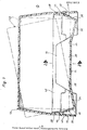
- the device shown has a cup-like container, designated as a whole as 10, which can be closed by means of a removable cover 12 which can be placed thereon.
- Partitions 16 forming compartments are arranged on the floor at a parallel distance from one another, together with the floor. These dividing walls forming side walls of the receiving compartments extend symmetrically to the transverse center of the container 10, which is rectangular in plan, and end at a greater distance from its longitudinal side walls 18, 20.
- the device is designed, for example, for storing cassettes with a tape-shaped recording medium, and it is assumed that these cassettes are so-called video cassettes for recording television programs.
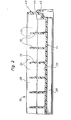
- a video cassette set in a receiving compartment of the container 10 is designated as a whole by 22.
- the distance between the partitions 16 can also be chosen so that such video cassettes and case in the opening. have the storage compartments parked.
- the bottom 14 has two tilting edges 24, 26 which extend parallel to the transverse center of the container. These tilting edges are formed by a total of three base partial surfaces 28, 30, 32 of the receiving compartments designated by 34.
- the middle bottom section 30 is in the erected state of the container in a horizontal plane, from which the two outer bottom surfaces 28, 32 extend obliquely outwards and downwards to form the tilting edges 24, 26.
- These bottom partial surfaces of the receiving compartments are approximately only half as long as the horizontal bottom partial surface 30, so that a stable mounting of the video cassettes 22 is ensured in the receiving compartments.
- the longitudinal side walls 18, 20 of the container that delimit the front compartments have a lower wall section 36 that extends obliquely upwards and outwards from below. This wall section is followed by a vertical wall section 38.
- the longitudinal side walls 18, 20 formed by these wall sections form sections of a peripheral wall surrounding the container, which thus also has end walls 40.
- the vertical wall section 38 forms, together with a downward circumferential skirt 42 on the container, a support shoulder 44 on which the cover 12 is removably seated. Accordingly, the projecting collar forming a vertical wandteil- "Tück into the container and fixes it on the cup-like container 10th
- the inclined arrangement of the wall part 36 of the longitudinal side walls 18, 20 creates a degree of freedom in the region of the end faces of the video cassettes 22 set in the receiving compartments 34 of the device, which makes it possible to remove video cassettes from the receiving compartments by tilting them by one to tilt the two tilting edges 24, 26 so that they emerge from the group of cassettes stored in the cup-like container 10 with their upper corner regions in such a way that they can be gripped advantageously.
- the arrangement of the tilting edges on the bottom of the receiving compartments 34 made it possible to dispense with a special mechanism for providing the cassettes in a removal position for this inclination of the video cassettes.
- a video cassette brought into one of the two possible removal positions by tipping is indicated by dash-dotted lines.
- a design variant of the device shown could also be to provide only one tilting edge 24 or 26 on the bottom of the receiving compartments 36.
- the invention is not limited to the construction variant described above. It also permits a design of the device in which it is angular in cross-section in a known manner, and in which the receiving compartments have both a bottom and a rear wall and angled side walls. Basically, the device can have any conceivable design because, according to the invention, it is only a matter of designing the bottom of the storage compartments in such a way that it is possible to incline the objects placed in the storage compartments for the purpose of their removal by tipping.
Landscapes
- Packaging Of Annular Or Rod-Shaped Articles, Wearing Apparel, Cassettes, Or The Like (AREA)
Applications Claiming Priority (2)
| Application Number | Priority Date | Filing Date | Title |
|---|---|---|---|
| DE7922878U | 1979-08-10 | ||
| DE7922878 | 1979-08-10 |
Publications (1)
| Publication Number | Publication Date |
|---|---|
| EP0023977A1 true EP0023977A1 (fr) | 1981-02-18 |
Family
ID=6706495
Family Applications (1)
| Application Number | Title | Priority Date | Filing Date |
|---|---|---|---|
| EP80104043A Withdrawn EP0023977A1 (fr) | 1979-08-10 | 1980-07-12 | Dispositif pour ranger des objets, notamment des cassettes à bande d'enregistrement |
Country Status (1)
| Country | Link |
|---|---|
| EP (1) | EP0023977A1 (fr) |
Cited By (3)
| Publication number | Priority date | Publication date | Assignee | Title |
|---|---|---|---|---|
| US4775049A (en) * | 1986-10-06 | 1988-10-04 | Ernst Stadelmann Gesellschaft M.B.H. | Container for generally flat articles |
| EP0335572A2 (fr) * | 1988-03-30 | 1989-10-04 | Wright Line Inc. | Système d'emmagasinage et de distribution |
| JPH0651173U (ja) * | 1992-12-22 | 1994-07-12 | 株式会社岡村製作所 | 磁気テープケース等の保持枠 |
Citations (7)
| Publication number | Priority date | Publication date | Assignee | Title |
|---|---|---|---|---|
| FR2010916A1 (fr) * | 1968-06-14 | 1970-02-20 | Stembel Oren | |
| US3743081A (en) * | 1971-02-25 | 1973-07-03 | Grace W R & Co | Cassette album container |
| US3811745A (en) * | 1972-09-29 | 1974-05-21 | E Cylke | Cassette carrier |
| DE2427103A1 (de) * | 1974-06-05 | 1975-12-18 | Idn Invention Dev Novelties | Behaelter zur aufbewahrung von magnetbandkassetten |
| FR2274109A1 (fr) * | 1974-06-05 | 1976-01-02 | Idn Invention Dev Novelties | Recipient de rangement pour cassettes a bandes magnetiques |
| DE2507620A1 (de) * | 1975-02-21 | 1976-09-02 | Wittner Rudolf | Kassettenbehaelter |
| FR2412136A1 (fr) * | 1977-12-16 | 1979-07-13 | Novita Stella Di Stella Ettore | Malette destinee a contenir des cassettes de rubans magnetiques |
-
1980
- 1980-07-12 EP EP80104043A patent/EP0023977A1/fr not_active Withdrawn
Patent Citations (8)
| Publication number | Priority date | Publication date | Assignee | Title |
|---|---|---|---|---|
| FR2010916A1 (fr) * | 1968-06-14 | 1970-02-20 | Stembel Oren | |
| US3743081A (en) * | 1971-02-25 | 1973-07-03 | Grace W R & Co | Cassette album container |
| US3811745A (en) * | 1972-09-29 | 1974-05-21 | E Cylke | Cassette carrier |
| DE2427103A1 (de) * | 1974-06-05 | 1975-12-18 | Idn Invention Dev Novelties | Behaelter zur aufbewahrung von magnetbandkassetten |
| FR2274109A1 (fr) * | 1974-06-05 | 1976-01-02 | Idn Invention Dev Novelties | Recipient de rangement pour cassettes a bandes magnetiques |
| FR2274106A1 (fr) * | 1974-06-05 | 1976-01-02 | Idn Invention Dev Novelties | Recipient de rangement de cassettes a bande magnetique |
| DE2507620A1 (de) * | 1975-02-21 | 1976-09-02 | Wittner Rudolf | Kassettenbehaelter |
| FR2412136A1 (fr) * | 1977-12-16 | 1979-07-13 | Novita Stella Di Stella Ettore | Malette destinee a contenir des cassettes de rubans magnetiques |
Cited By (4)
| Publication number | Priority date | Publication date | Assignee | Title |
|---|---|---|---|---|
| US4775049A (en) * | 1986-10-06 | 1988-10-04 | Ernst Stadelmann Gesellschaft M.B.H. | Container for generally flat articles |
| EP0335572A2 (fr) * | 1988-03-30 | 1989-10-04 | Wright Line Inc. | Système d'emmagasinage et de distribution |
| EP0335572A3 (en) * | 1988-03-30 | 1990-06-13 | Wright Line Inc. | Storing and dispensing system |
| JPH0651173U (ja) * | 1992-12-22 | 1994-07-12 | 株式会社岡村製作所 | 磁気テープケース等の保持枠 |
Similar Documents
| Publication | Publication Date | Title |
|---|---|---|
| DE3410480C2 (fr) | ||
| EP0253102A1 (fr) | Récipient de stockage pour cassettes à bande magnétique | |
| EP0476343A2 (fr) | Boîte pour jeux de tournevis | |
| DE3730813C1 (de) | Bandkassettengehaeuse mit Kopplungselementen | |
| EP0023977A1 (fr) | Dispositif pour ranger des objets, notamment des cassettes à bande d'enregistrement | |
| DE2525169A1 (de) | Kunststoff-flaschenkasten mit verriegelungsvorrichtung | |
| EP0360987B1 (fr) | Boîte à outils | |
| DE2046248A1 (de) | Durchlichtbildmagazin | |
| DE4021257A1 (de) | Lade fuer einen aquarienunterbau | |
| DE6800540U (de) | Vorrichtung fuer den transport von flaschen | |
| DE8137602U1 (de) | Stapelbarer ablagebehaelter mit auszugschublade | |
| EP0367168B1 (fr) | Casier à bouteilles | |
| DE7922878U1 (de) | Vorrichtung zum Aufbewahren von Gegenständen, insbesondere Kassetten mit einem bandförmigen Aufzeichnungsträger | |
| DE2615457A1 (de) | Magazin | |
| DE3508490A1 (de) | Vorrichtung zum differenzierten speichern von frage- und antwortkarten | |
| EP0896863A2 (fr) | Râtelier de boíte à outils | |
| EP0927564B1 (fr) | Boíte à enchères de bridge | |
| DE2005601C (de) | Stapelbare Ablageschale | |
| EP0487824B1 (fr) | Casier à bouteilles en matière plastique | |
| EP0201664B1 (fr) | Présentoir pour la vente de lacets de souliers, d'emballages de lacets de souliers ou d'articles d'assortiment similaires | |
| DE1486219A1 (de) | Tubenbehaelter | |
| DE4402219A1 (de) | Stapelbehälter | |
| DE2600025C2 (de) | Schubkastenschrank | |
| DE1168332B (de) | Aufbewahrungsbehaelter fuer Dia-Magazine | |
| DE202018101695U1 (de) | Kiste mit Deckel |
Legal Events
| Date | Code | Title | Description |
|---|---|---|---|
| PUAI | Public reference made under article 153(3) epc to a published international application that has entered the european phase |
Free format text: ORIGINAL CODE: 0009012 |
|
| AK | Designated contracting states |
Designated state(s): AT BE CH IT NL SE |
|
| 17P | Request for examination filed |
Effective date: 19810518 |
|
| STAA | Information on the status of an ep patent application or granted ep patent |
Free format text: STATUS: THE APPLICATION HAS BEEN WITHDRAWN |
|
| 18W | Application withdrawn |
Withdrawal date: 19820825 |
|
| RIN1 | Information on inventor provided before grant (corrected) |
Inventor name: HAERLE, FRITZ |