EP0022993A1 - Procédé et machine pour récolter les collets et les feuilles de betteraves - Google Patents
Procédé et machine pour récolter les collets et les feuilles de betteraves Download PDFInfo
- Publication number
- EP0022993A1 EP0022993A1 EP80104000A EP80104000A EP0022993A1 EP 0022993 A1 EP0022993 A1 EP 0022993A1 EP 80104000 A EP80104000 A EP 80104000A EP 80104000 A EP80104000 A EP 80104000A EP 0022993 A1 EP0022993 A1 EP 0022993A1
- Authority
- EP
- European Patent Office
- Prior art keywords
- beet
- knife
- wiper
- head
- button
- Prior art date
- Legal status (The legal status is an assumption and is not a legal conclusion. Google has not performed a legal analysis and makes no representation as to the accuracy of the status listed.)
- Granted
Links
Images
Classifications
-
- A—HUMAN NECESSITIES
- A01—AGRICULTURE; FORESTRY; ANIMAL HUSBANDRY; HUNTING; TRAPPING; FISHING
- A01D—HARVESTING; MOWING
- A01D23/00—Topping machines
- A01D23/06—Topping machines with collecting and depositing devices for the tops; Devices for protecting the tops against damage
-
- A—HUMAN NECESSITIES
- A01—AGRICULTURE; FORESTRY; ANIMAL HUSBANDRY; HUNTING; TRAPPING; FISHING
- A01D—HARVESTING; MOWING
- A01D23/00—Topping machines
- A01D23/02—Topping machines cutting the tops before being lifted
- A01D2023/026—Devices with movable knives for topping, e.g. rotatable cutting disks
- A01D2023/028—Cutters rotating around a shaft forming a cutting rotor
Definitions
- the invention relates to a method for harvesting beet heads and beet leaf, in which first the beet leaf is knocked off the beet and chopped and fed to a conveying device, and then the head slice is cut off individually depending on the height of the beet, and a device for harvesting beet heads and beet leaf, consisting of a chopper that is adjustable in its working height, which cuts off, chops and conveys the main part of the beet leaf, as well as a downstream head device consisting of grinding buttons and knife, with which the head disc is cut off.
- a known device for harvesting beet heads and beet leaves has a harvester that is adjustable in its working height, which cuts off, chops and feeds the main part of the beet leaves and feeds it to a transport screw, a downstream cleaning device with which the remaining petioles on the beet head are chopped off or chopped off, and one of these Cleaning device downstream from grinding button and knife existing head device with which the top slices of the beets are cut off.
- head slices fall on the beet field, where they either remain and are later plowed in, which is not favorable for the arable soil, or they are picked up together with the beets by the beet harvesting device that subsequently works, and finally end up in the sugar factory, which is disadvantageous because the Separation of head slices and beets imposed on the sugar factory to carry out additional operations of reading the head slices.
- the second chopper throws chops separate the shredded head disks to the rear against another deflection plate, which directs the shredded head disks to the front into the beet leaf screw conveyor in front of the second chopper.
- the two choppers form a considerable amount of construction work, which is used only poorly because the second chopper has very little mass to shred, while the effort in terms of weight, installation space and costs is great.
- the invention consists in that after the cut the head disc is changed in its direction of movement by approximately 150-190 0 , thrown back (ie thrown in the direction of travel of the harvester) and fed to the chopping process of the beet leaf.
- the head disc By changing the direction of movement of the head disc after cutting this head disc, it is achieved that the head disc is thrown into the chopper for the beet leaf against the direction of travel of the harvesting machine and is crushed there together with the beet leaf.
- the existing device with its upward-facing surface can be used to catch, stop and temporarily store the beet head disks before they move back, until several head disks have pushed in front of the return conveyor, are caught by them and thrown into the chopper .
- the device according to the invention for harvesting beet heads and beet leaves is characterized in that a rotating wiper is provided above the button and knife, which has the same direction of rotation as the chopping device and that the top of the button serves and is designed as a guide for the head disks.
- this wiper rotates with the lower part of its circumferential path in the direction of the movement of the firing machine, so that the chopper device directs the beet leaf forward against a deflection plate, while the beet head disks are also thrown forward by the wiper and thereby into the Chopper fall, which cuts these beet head slices together with the beet leaf.
- the chopper is used both for chopping off the beet leaves and for crushing the beet leaf and beet head slices and for transporting the crushed beet leaves and beet head slices into a conveying device which, above the axes of the chopper and the wiper, is close-fitting is.
- a rotating shaft to which elastic strips are attached serves as the wiper. The circumferential path of these elastic strips runs above the beet heads, namely above the knife and the feeler.
- the knife and a collecting grate or a collecting plate connected to the knife form a catching device for the head disks so that they cannot fall on the field.
- the beet head disks are collected in this catching device until they are caught by the circumference of the rotating wiper and are thrown into the chopping device.
- the knife and collecting grate or collecting plate are curved, the imaginary center of this curvature being approximately between the axes of the chopper and the wiper.
- the wiper from Strei fen is formed and the button and / or collecting grate consist of flat bars arranged upright. Then the strips of the wiper can reach between the flat bars arranged upright and grasp the head discs safely and throw them into the chopper.
- buttons surface is adapted to the radius of the wiper, because this ensures that beet head disks can be gripped by the wiper as best as possible and can be thrown into the chopper.
- the swiveling axis of the head device is located between the chopper and the wiper, preferably in the triangle above their lower common tangent.
- the head device can also be attached to a lever parallelogram, the articulation points of which lie at least partially between the wiper strips.
- the knife is advantageously arranged so that it lies behind the projection of the axis of the wiper on the field (or the horizontal).
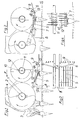
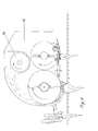
- the device of Fig. 1 consists of a chopper 1 of known type which rotates clockwise with the shaft 2.
- a guide plate 3 is attached in front of the chopper 1, with which the chopped beet leaf is thrown into a transport channel 4, from which the shredded beet leaf is conveyed by means of a not shown transporter is transported away.
- Behind the chopper 1 (seen in the direction of travel F) is the head device, which consists of a grinding button 5 and a knife 6.
- the grinding button 5 is formed from a series of flat irons 7 arranged parallel to one another in an upright position. These flat irons are pivotally arranged around the shaft 8 at one end.
- One laterally arranged flat iron 7A carries the knife 6.
- the cutting edge of the knife 6 is directed in the direction of travel F.
- the knife 6 carries on its rear edge rods 9 of a grate, which are bent such that their free ends in Show direction of travel.
- a rotating wiper 10 which is driven by a shaft 11, on which pivotable strips 12 are arranged, which are preferably made of elastic material.
- This wiper rotates in the same direction of rotation as the chopper 1, namely clockwise.
- the elastic strips 12 of the wiper 10 are arranged so that they engage between the catch rods 9 behind the knife 6 and between the flat iron 7 when the head device is pressed upwards as a result of a beet that has grown out of the field.
- a transport screw 14 is arranged above the axes 2 and 11 of chopper 1 and wiper 10, which is located in a transport trough 15 and is used for the transport of the chopped material. Since this transport screw 14 is also driven in the same direction of rotation as the chopper and the wiper, and since all three shafts of chopper, wiper and conveyor screw 14 are firmly in their axial position within the frame of the device, a drive which is extremely easy to construct can be used.
Landscapes
- Life Sciences & Earth Sciences (AREA)
- Environmental Sciences (AREA)
- Harvesting Machines For Root Crops (AREA)
Applications Claiming Priority (2)
| Application Number | Priority Date | Filing Date | Title |
|---|---|---|---|
| DE2929783 | 1979-07-23 | ||
| DE19792929783 DE2929783A1 (de) | 1979-07-23 | 1979-07-23 | Verfahren und vorrichtung zum ernten von ruebenkoepfen und ruebenblatt |
Publications (2)
| Publication Number | Publication Date |
|---|---|
| EP0022993A1 true EP0022993A1 (fr) | 1981-01-28 |
| EP0022993B1 EP0022993B1 (fr) | 1983-07-20 |
Family
ID=6076515
Family Applications (1)
| Application Number | Title | Priority Date | Filing Date |
|---|---|---|---|
| EP80104000A Expired EP0022993B1 (fr) | 1979-07-23 | 1980-07-11 | Procédé et machine pour récolter les collets et les feuilles de betteraves |
Country Status (2)
| Country | Link |
|---|---|
| EP (1) | EP0022993B1 (fr) |
| DE (1) | DE2929783A1 (fr) |
Cited By (1)
| Publication number | Priority date | Publication date | Assignee | Title |
|---|---|---|---|---|
| GB2181934A (en) * | 1985-10-25 | 1987-05-07 | Svernska Sockerfabriks Ab | Beet topping assembly |
Families Citing this family (3)
| Publication number | Priority date | Publication date | Assignee | Title |
|---|---|---|---|---|
| DE3140976A1 (de) * | 1981-10-15 | 1983-05-11 | Werner 4787 Geseke Schulte | Ruebenblatterntevorrichtung |
| CS244455B1 (en) * | 1983-09-05 | 1986-07-17 | Josef Soucek | Sugar beat cropping device |
| DE3340714A1 (de) * | 1983-11-10 | 1985-05-30 | Mathias 8061 Prittlbach Wackerl | Vorrichtung zum koepfen von mit blaettern versehenen, im erdboden steckenden rueben |
Citations (3)
| Publication number | Priority date | Publication date | Assignee | Title |
|---|---|---|---|---|
| FR1136494A (fr) * | 1954-11-09 | 1957-05-23 | Heinrich Lanz Ag | Dispositif à palpeur rotatif pour l'étêtage des betteraves |
| GB1147304A (en) * | 1967-07-04 | 1969-04-02 | Bodenbearbeitungsgerate Veb | Improvements in and relating to agricultural machinery |
| FR2312187A1 (fr) * | 1975-05-28 | 1976-12-24 | Franquet Gilbert | Effeuilleuse pour plantes cultivees |
Family Cites Families (1)
| Publication number | Priority date | Publication date | Assignee | Title |
|---|---|---|---|---|
| DE7727630U1 (fr) * | 1900-01-01 | Wilhelm Stoll Maschinenfabrik Gmbh, 3325 Lengede |
-
1979
- 1979-07-23 DE DE19792929783 patent/DE2929783A1/de active Granted
-
1980
- 1980-07-11 EP EP80104000A patent/EP0022993B1/fr not_active Expired
Patent Citations (3)
| Publication number | Priority date | Publication date | Assignee | Title |
|---|---|---|---|---|
| FR1136494A (fr) * | 1954-11-09 | 1957-05-23 | Heinrich Lanz Ag | Dispositif à palpeur rotatif pour l'étêtage des betteraves |
| GB1147304A (en) * | 1967-07-04 | 1969-04-02 | Bodenbearbeitungsgerate Veb | Improvements in and relating to agricultural machinery |
| FR2312187A1 (fr) * | 1975-05-28 | 1976-12-24 | Franquet Gilbert | Effeuilleuse pour plantes cultivees |
Cited By (2)
| Publication number | Priority date | Publication date | Assignee | Title |
|---|---|---|---|---|
| GB2181934A (en) * | 1985-10-25 | 1987-05-07 | Svernska Sockerfabriks Ab | Beet topping assembly |
| GB2181934B (en) * | 1985-10-25 | 1989-09-20 | Svernska Sockerfabriks Ab | Beet topping assembly |
Also Published As
| Publication number | Publication date |
|---|---|
| EP0022993B1 (fr) | 1983-07-20 |
| DE2929783A1 (de) | 1981-02-12 |
| DE2929783C2 (fr) | 1988-02-04 |
Similar Documents
| Publication | Publication Date | Title |
|---|---|---|
| EP2050325B1 (fr) | Récolteuse de betteraves, notamment sous la forme d'une récolteuse complète automobile | |
| DE2322136A1 (de) | Zuckerrohr-erntemaschine | |
| DE19959282A1 (de) | Einzugs- und Pflückeinrichtung mit Häckseleinrichtung | |
| DE19959338A1 (de) | Einzugs- und Pflückeinrichtung sowie Erntemaschine | |
| EP0069898B1 (fr) | Récolteuse à rangs multiples, notamment pour mais | |
| DE10351858B4 (de) | Maschine zum Mähen von stängelartigem Erntegut | |
| DE296075C (fr) | ||
| DE3623380A1 (de) | Verfahren und vorrichtung zur reihenunabhaengigen maisernte | |
| WO1988002983A2 (fr) | Moissonneuse a vis sans fin | |
| DE202012009832U1 (de) | Vorrichtung zur Aufbereitung von Rüben | |
| DE2933223A1 (de) | Verfahren zum ernten von zuckerrohr und vorrichtung zur durchfuehrung des verfahrens | |
| EP3130214B1 (fr) | Faucheuse destinée à transporter et à cueillir des produits de récolte à tiges | |
| EP0022993B1 (fr) | Procédé et machine pour récolter les collets et les feuilles de betteraves | |
| DE202015005648U1 (de) | Mäh- und Fördergerät zum Ernten von stängeligem Erntegut | |
| DE821568C (de) | Hackfruchterntemaschine | |
| DE2834463A1 (de) | Koepfvorrichtung zum koepfen von rueben | |
| DE102019007585A1 (de) | Reihenunabhängiges Vorsatzgerät zum Ernten stängelförmiger Pflanzen mit einem quer zur Fahrtrichtung liegenden, durch das ganze Vorsatzgerät durchgehenden Pflückspalt | |
| DE2320126C2 (de) | Feldhäcksler | |
| DE2459883A1 (de) | Vorrichtung zum schneiden und ernten von mais unter verwendung gegensinnig rotierender foerderkreisel | |
| EP0077459B1 (fr) | Dispositif de récolte de feuilles de betteraves | |
| DE3101770C2 (de) | Vorrichtung zum Entblättern von in Reihen wachsenden Wurzelfrüchten vor dem Roden | |
| DE2643081A1 (de) | Einrichtung an einem maehwerk zum aufbereiten landwirtschaftlicher halmgueter und verwendung dieser einrichtung | |
| EP3141104B1 (fr) | Cueilleur à maïs avec dispositif d'andainage | |
| DE3343663C2 (de) | Rübenköpfeinrichtung | |
| DE3153261C2 (en) | Cutting appliance for stalky cereals, especially for machines for the harvesting of maize |
Legal Events
| Date | Code | Title | Description |
|---|---|---|---|
| PUAI | Public reference made under article 153(3) epc to a published international application that has entered the european phase |
Free format text: ORIGINAL CODE: 0009012 |
|
| AK | Designated contracting states |
Designated state(s): BE CH FR GB LI NL SE |
|
| 17P | Request for examination filed |
Effective date: 19810407 |
|
| GRAA | (expected) grant |
Free format text: ORIGINAL CODE: 0009210 |
|
| STAA | Information on the status of an ep patent application or granted ep patent |
Free format text: STATUS: THE PATENT HAS BEEN GRANTED |
|
| AK | Designated contracting states |
Designated state(s): BE CH FR GB LI NL SE |
|
| PG25 | Lapsed in a contracting state [announced via postgrant information from national office to epo] |
Ref country code: SE Effective date: 19830720 |
|
| ET | Fr: translation filed | ||
| PLBI | Opposition filed |
Free format text: ORIGINAL CODE: 0009260 |
|
| PGFP | Annual fee paid to national office [announced via postgrant information from national office to epo] |
Ref country code: CH Payment date: 19840618 Year of fee payment: 5 |
|
| 26 | Opposition filed |
Opponent name: FRANZ KLEINE MASCHINENFABRIK GMBH & CO. Effective date: 19840419 |
|
| PLBJ | Opposition found inadmissible |
Free format text: ORIGINAL CODE: 0009275 |
|
| 26U | Opposition found inadmissible |
Opponent name: FRANZ KLEINE MASCHINENFABRIK GMBH & CO. Effective date: 19850710 |
|
| REG | Reference to a national code |
Ref country code: FR Ref legal event code: ST |
|
| NLXE | Nl: other communications concerning ep-patents (part 3 heading xe) |
Free format text: IN PAT.BUL.16/84,PAGE 1795 OPPOSITION HAS BEEN DECLARED INADMISSABLE |
|
| REG | Reference to a national code |
Ref country code: FR Ref legal event code: AR |
|
| REG | Reference to a national code |
Ref country code: FR Ref legal event code: CL |
|
| PGFP | Annual fee paid to national office [announced via postgrant information from national office to epo] |
Ref country code: NL Payment date: 19870731 Year of fee payment: 8 |
|
| REG | Reference to a national code |
Ref country code: FR Ref legal event code: BR |
|
| PG25 | Lapsed in a contracting state [announced via postgrant information from national office to epo] |
Ref country code: GB Effective date: 19880711 |
|
| PG25 | Lapsed in a contracting state [announced via postgrant information from national office to epo] |
Ref country code: LI Effective date: 19880731 Ref country code: CH Effective date: 19880731 |
|
| GBPC | Gb: european patent ceased through non-payment of renewal fee | ||
| REG | Reference to a national code |
Ref country code: CH Ref legal event code: PL |
|
| PG25 | Lapsed in a contracting state [announced via postgrant information from national office to epo] |
Ref country code: NL Effective date: 19900201 |
|
| NLV4 | Nl: lapsed or anulled due to non-payment of the annual fee | ||
| PGFP | Annual fee paid to national office [announced via postgrant information from national office to epo] |
Ref country code: FR Payment date: 19900530 Year of fee payment: 11 |
|
| PGFP | Annual fee paid to national office [announced via postgrant information from national office to epo] |
Ref country code: BE Payment date: 19900809 Year of fee payment: 11 |
|
| PG25 | Lapsed in a contracting state [announced via postgrant information from national office to epo] |
Ref country code: BE Effective date: 19910731 |
|
| BERE | Be: lapsed |
Owner name: SCHULTE WERNER Effective date: 19910731 |
|
| PG25 | Lapsed in a contracting state [announced via postgrant information from national office to epo] |
Ref country code: FR Effective date: 19920331 |
|
| REG | Reference to a national code |
Ref country code: FR Ref legal event code: ST |