EP0022251B1 - Vanne pour conduite avec un corps incorporable pour l'échange du passe-diable nettoyeur, pouvant être raccordé à des tuyaux dans lesquels circulent des liquides épais sous pression, en particulier du béton - Google Patents
Vanne pour conduite avec un corps incorporable pour l'échange du passe-diable nettoyeur, pouvant être raccordé à des tuyaux dans lesquels circulent des liquides épais sous pression, en particulier du béton Download PDFInfo
- Publication number
- EP0022251B1 EP0022251B1 EP80103787A EP80103787A EP0022251B1 EP 0022251 B1 EP0022251 B1 EP 0022251B1 EP 80103787 A EP80103787 A EP 80103787A EP 80103787 A EP80103787 A EP 80103787A EP 0022251 B1 EP0022251 B1 EP 0022251B1
- Authority
- EP
- European Patent Office
- Prior art keywords
- pipe
- concrete
- wiper
- chamber
- feed
- Prior art date
- Legal status (The legal status is an assumption and is not a legal conclusion. Google has not performed a legal analysis and makes no representation as to the accuracy of the status listed.)
- Expired
Links
- 238000004140 cleaning Methods 0.000 title claims description 16
- 239000012530 fluid Substances 0.000 title 1
- 238000010276 construction Methods 0.000 claims description 5
- 238000013022 venting Methods 0.000 claims description 2
- 239000000126 substance Substances 0.000 claims 1
- 210000000056 organ Anatomy 0.000 description 12
- XLYOFNOQVPJJNP-UHFFFAOYSA-N water Substances O XLYOFNOQVPJJNP-UHFFFAOYSA-N 0.000 description 7
- 238000009415 formwork Methods 0.000 description 4
- 238000000034 method Methods 0.000 description 4
- 238000009434 installation Methods 0.000 description 2
- 239000000463 material Substances 0.000 description 2
- 238000000926 separation method Methods 0.000 description 2
- 230000005540 biological transmission Effects 0.000 description 1
- 230000000903 blocking effect Effects 0.000 description 1
- 238000011109 contamination Methods 0.000 description 1
- 239000013536 elastomeric material Substances 0.000 description 1
- 239000002184 metal Substances 0.000 description 1
- 238000002360 preparation method Methods 0.000 description 1
- 238000005086 pumping Methods 0.000 description 1
- 239000002002 slurry Substances 0.000 description 1
Images


Classifications
-
- B—PERFORMING OPERATIONS; TRANSPORTING
- B08—CLEANING
- B08B—CLEANING IN GENERAL; PREVENTION OF FOULING IN GENERAL
- B08B9/00—Cleaning hollow articles by methods or apparatus specially adapted thereto
- B08B9/02—Cleaning pipes or tubes or systems of pipes or tubes
- B08B9/027—Cleaning the internal surfaces; Removal of blockages
- B08B9/04—Cleaning the internal surfaces; Removal of blockages using cleaning devices introduced into and moved along the pipes
- B08B9/053—Cleaning the internal surfaces; Removal of blockages using cleaning devices introduced into and moved along the pipes moved along the pipes by a fluid, e.g. by fluid pressure or by suction
- B08B9/055—Cleaning the internal surfaces; Removal of blockages using cleaning devices introduced into and moved along the pipes moved along the pipes by a fluid, e.g. by fluid pressure or by suction the cleaning devices conforming to, or being conformable to, substantially the same cross-section of the pipes, e.g. pigs or moles
- B08B9/0552—Spherically shaped pigs
Definitions
- the invention relates to a pipeline fitting with a housing which can be installed in lines which convey pressurized thick materials, preferably concrete, for changing a wiper, preferably a ball, which is pressed through the line with a pressure medium.
- the invention is explained below on the basis of its preferred field of application, although it is applicable not only to the cleaning of concrete delivery lines but also to other thick material conveying pipes which e.g. Can convey slurries of pulpy to sludge-like consistency, which solidify in the pipeline when the conveying movement stops for a long time.
- This is particularly unpleasant for concrete, because hardening concrete causes blockages in metal pipes that are practically no longer removable. Therefore, at the end of the concrete delivery, concrete delivery lines not only have to be emptied, but also wiped clean.
- the method presupposes that the prefilling container has a sufficiently large volume to accommodate the concrete sucked back.
- the prefilling container dimensions are often not sufficient. This leads to contamination of the components lying outside the prefilling container and their surroundings when the residual concrete is sucked back.
- the concrete that has been sucked back must be emptied from the prefill container. As a rule, there is no use for this at the end of concrete delivery; therefore concrete losses occur, which are considerable due to the large pipe diameter.
- the construction site is contaminated with the residual concrete because the excess concrete is usually deposited there.
- the invention has for its object to provide a pipeline fitting that can remain in the pipeline, the deportation is spared and can even be cleaned with the wiper.
- this object is achieved by a mutually adjustable member which has a through-pipe which can be aligned with the pipeline and a pipe chamber made of a blind pipe which receives the wiper, the bottom of which has a connecting channel to the pressure medium connection arranged on the outside.
- the organ can be switched over so that the through-pipe still filled with concrete is also emptied when the wiper is sucked back and the subsequent pipe section is emptied into the pre-filling container. Since the pipeline fitting according to the invention can be installed in the delivery line in the immediate vicinity of the prefilling container, the loss of this residual amount is irrelevant.
- the mutually adjustable member is designed as a slide, in which the through tube and the blind tube are arranged axially parallel.
- a slide can be operated in a known manner by hand, but also with the aid of an adjusting motor.
- the pressure medium connection is preferably provided with a T-piece, to which a pressure gauge and a venting or relief member can be connected.
- the organ with the fitting permanently installed in the pipeline to use the through pipe for the conveying of concrete and to use the pipe chamber to wipe the wiper change, at the same time the pipeline is shut off with the bottom of the dummy pipe.
- the pressure medium - pressurized water or compressed air - then needs to be cleared the way through the connecting channel.
- the wiper then pushes the remaining concrete out of the pipeline and wipes the pipes clean.
- the slide must be actuated without the medium under pressure in the line being able to escape to the outside. This presupposes that both ends of the through tube in the valve housing are sealed on a plate, the tube ends sliding on the plates assigned to them during the changeover process.
- These seals require extensive housings and are problematic for technical and economic reasons. As a result, the housing must be installed in the delivery line as a separate structural unit behind a pump, for example a concrete pump. This prevents the delivery line from being easily connected to the pump.
- a through-tube is designed as a curved swivel body, the outlet end of which is connected to the delivery line with a joint and the inlet end of which is movable on a plate which defines the opening for a tube chamber arranged behind the plate and for a tubular inlet of the delivery line, the tube chamber consisting of a wiper receiving blind tube, the bottom of which has a connecting channel to the pressure medium connection arranged on the outside.
- This embodiment of the invention results in a simplified housing and the possibility of reducing the amount of residual concrete that has to be accommodated in the prefilling container.
- the passage tube is kept in constant, albeit articulated, connection with the delivery line due to its design as a swivel body, no plate seal is required at the conveying end of the passage tube and the housing can therefore be simplified accordingly.
- the through pipe also serves to connect the pipe chamber to the delivery line, it is cleaned together with the delivery line in one operation. As a result, the residual flow rate which is removed from the conveying path when sucking back is reduced accordingly.
- the possibility is created of permanently installing the pipe fitting directly behind a pump, in particular a concrete pump, without having to interrupt the delivery line immediately before the pump, as was previously the case.
- the short distance of the pump pistons from the valve then enables the remaining amount of thick matter to be sucked off into the prefilling container, so that the entire conveying path is cleaned in a simple manner after the completion of the conveying.
- a further simplification of the overall structure of a thick matter pump, in particular a concrete pump, on which the valve according to the invention is to be permanently installed is achieved in that the swivel body connects the two alternately filling and delivering delivery cylinders of a piston pump, which form the tubular inlet, to the delivery line , wherein the plate for each feed cylinder and the tube chamber has recesses and is arranged on one side of the prefill container of the pump.
- the housing of the switching element of the piston pump is used as the housing of the valve, whereby only a tube chamber is provided on the existing housing and the swivel body, which is already present in such a housing, is used as a through-tube because it cleans the housing during cleaning Pumping stops anyway.
- the through-tube of the fitting according to the invention can be given the designs customary in the case of such change-over members of piston pumps, in particular concrete pumps. It can therefore be bent in an S-shape, but can also be achieved with a simple pipe bend.
- 1 denotes a concrete delivery line which is carried, for example, by a concrete placing boom, not shown.
- a housing 4 is flanged, which belongs to the pipeline fitting generally designated 5.
- the housing 4 is installed in the line 1 in this way.
- the installation point is located just behind a prefill container, not shown, to which the pipe 6 leads.
- the line has a mutually adjustable organ, which is generally designated 7.
- the organ consists of a structural unit that combines a through tube 8 and a tube chamber 9.
- the tube chamber consists of a blind tube 9 ', the bottom 10 of which is provided with a connecting channel (FIG. 2) which bears the reference number 11.
- the connecting channel has a section 12 which is arranged axially to the blind pipe 9 and a section 13 which is angled in relation thereto and which runs transversely to the axis of the delivery line 1 and accordingly leads outwards.
- a tap 17 enables the delivery line 1 to be emptied in the open state.
- the organ 7 described is designed as a slide which can be adjusted in two operating positions in a plane orthogonal to the line axis.
- the blind pipe 9 lies outside the housing 4.
- the wiper, generally designated (19) at 19 can be inserted in the form of a ball into the tube chamber, which is formed by the blind pipe 9 '.
- the through pipe 8 is aligned with the delivery line 1 and the connecting pipe 6.
- concrete 20 can be pressed from the prefilling container into line 1 and conveyed using the pump, not shown.
- the entire pipeline including the mutually adjustable member, must be cleared of the concrete, which would otherwise harden and block the delivery routes.
- the organ is moved into the other operating position, which is shown in Fig. 2. In this position, the pipe chamber is aligned with the delivery line 1, but the through pipe 8 filled with concrete is located within the housing 4 and is therefore not yet freed from the concrete.
- the delivery line 1 is emptied and wiped clean.
- pressurized water is pressed into the pipe chamber via the connection channel 11 via the connection 15 according to the exemplary embodiment.
- the wiper 19 is moved in the direction indicated by the arrows 22 and presses the residual concrete in front of it, which emerges at the end of the conveying line 1 and can be introduced into the formwork which has previously been filled with the conveying concrete.
- the wiper 19 moves again in the direction of the arrows 22.
- the wiper 19 is only required as far into the To press pipe 1 or in the housing 4 that the movement of the adjustable member 7 is released again.
- the organ 7 is moved back into its second position, which is shown in FIG. 6.
- the concrete pump (not shown) is sucked through the pipe 6 into the wiper body 19, which then pushes the residual concrete still contained in the through pipe 8 and in the line 6 in the direction of the arrows 24 and finally conveys it into the prefilling container.
- compressed air can also be used instead of pressurized water. Then you have to watch the manometer 16 closely, however, because air is compressible in contrast to pressurized water and therefore the residual concrete can suddenly emerge from the delivery line 1.
- a delivery line 101 for concrete 102 is separated at 103, so that there is a line section, not shown, which leads to a concrete pump.
- a housing 104 of a pipeline fitting is installed at the separation point. The housing be is limited to those parts that are required to transmit the separation forces and to connect the two line sections of the concrete delivery line 101.
- the housing then has a tubular inlet 105 for the incoming concrete, with which the housing can be flange-mounted, for example, on the concrete pump.
- the inlet pipe 105 sits on an end plate 106 of the housing 104, on which a pipe chamber 107 is also attached.
- the tube chamber is empty during the concrete delivery shown in FIG. 11 with the exception of a wiper 108, which has the shape of a ball in the exemplary embodiment shown.
- the tube chamber 107 has the shape of a blind tube and accordingly has a chamber base 109 which has a connection channel (not shown) to an external pressure medium connection, the function of which is explained below.
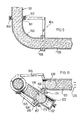
- a pivot axis 110 for a through pipe 111 the end of which is facing the plate 106 and is sealed thereon with the aid of a seal shown schematically at 112 in such a way that concrete escapes in every operating position and in every intermediate position 102 to the outside is prevented.
- the pipe end 114 opposite the sealed pipe end 113 is seated in a pipe joint 115 and is also, as schematically indicated at 117, sealed to the outside.
- the pipe joint 117 is connected to the plate 106 of the housing with a tie rod 118.
- the tie rod also serves to support a preferably hydraulic actuating cylinder 120 mounted at 119, which can actuate the through tube via a lever 121 so that it pivots about the axis 110, its seal 112 moving on the plate 106.
- a preferably hydraulic actuating cylinder 120 mounted at 119, which can actuate the through tube via a lever 121 so that it pivots about the axis 110, its seal 112 moving on the plate 106.
- the through tube 111 is rotated in the tubular joint 115 due to its design as an S-shaped curved swivel body, so that it remains in constant connection with the delivery line 101.
- the same or a further wiper 128 can also be introduced into the tubular inlet of the fitting and, by switching the pump in the direction of the arrows 129, can be pressed into the prefilling container usually provided in such pumps. The entire conveying path is then free of concrete.
- the valve described is integrated in the changeover element 130 of a concrete pump, generally designated 131.
- the concrete pump has two delivery cylinders 132, 133, each of which contains a piston which is actuated by working cylinders 134, 135.
- the conveying cylinders 132 and 133 work alternately in such a way that their pistons suck concrete when they return from a prefilling container 136, which is pressed into the conveying line 101 at the inlet. The changeover required for this takes place with the changeover element which is built into the prefilling container 136.
- the changeover member 130 has a movable swivel body 137 in the form of an S-shaped tube.
- the end 138 of the pivot body sits in a tubular joint at 139, while the opposite, i.e. the cylinder-side tube end 140 slides on a plate 141 and is sealed thereon.
- the pipe end 140 can be pivoted via the piston rod 143 of a hydraulic cylinder 144 into three positions, which are designated 1-111 in FIG. 7. Items I and 11 apply to concrete delivery.
- the delivery cylinder 133 sucks concrete out of the prefilling container 136, while at the same time the delivery cylinder 132 presses the previously sucked-in concrete through the swivel body 137 into the delivery line 101.
- the feed cylinders 132, 133 are reversed.
- the thrust piston gear 143, 144 and the tube end 140 are aligned with the tube chamber shown at 146, which has a removable tube plate 149.
- the detachability of the tube plate makes it possible to insert the cleaning body 150 into the tube chamber 146 from the outside, so that the prefilling container 136 does not need to be emptied before the wiper 150 is inserted. Otherwise, the swivel body 137 and the subsequent delivery line 101 can be cleaned in the manner of operation described in connection with FIGS. 11-13 by supplying pressure medium according to the arrows 151 into the tube chamber 146.
- the embodiment according to FIGS. 9 and 10 differs from the embodiment according to FIGS. 11-13 essentially by the design of the through tube.
- the through-pipe is designated 160 and is mounted with its end 161 in a pipe joint 162 which is sealed off at 163 and connects the end 161 to the delivery line 101.
- the housing is labeled 164 and again openly trained. It consists essentially of the angularly shaped anchors 165 and 166, and a curved plate 167, which carries the inlet 105 and the tube chamber 107.
- the other end 168 of the through tube 160 is provided with a correspondingly curved flange 169 which is movable on the inside 170 of the plate 167.
- the housing also has connections 171, 172 for fastening to the substructure of a mobile concrete pump.
- FIG. 9 shows the position of the parts during the conveying of concrete, in which the through pipe 160 is connected to the pipe inlet 105. 10 shows the parts in the position necessary for cleaning.
- the through pipe 160 is aligned with the pipe chamber 107, pressure medium being supplied in accordance with the arrows 122, so that the wiper 108 can press the concrete in front of it, while the wiper 128 is sucked back into the prefilling container in accordance with the arrows 129.
Landscapes
- Physics & Mathematics (AREA)
- Fluid Mechanics (AREA)
- Engineering & Computer Science (AREA)
- Mechanical Engineering (AREA)
- Reciprocating Pumps (AREA)
Claims (7)
Priority Applications (1)
| Application Number | Priority Date | Filing Date | Title |
|---|---|---|---|
| AT80103787T ATE3139T1 (de) | 1979-07-06 | 1980-07-03 | Rohrleitungsarmatur mit einem in leitungen, die unter druck stehende dickstoffe, vorzugsweise beton foerdern, einbaubaren gehaeuse zum einwechseln eines wischers. |
Applications Claiming Priority (4)
| Application Number | Priority Date | Filing Date | Title |
|---|---|---|---|
| DE19792927324 DE2927324C3 (de) | 1979-07-06 | 1979-07-06 | Rohrleitungsarmatur mit einem in Leitungen, die unter Druck stehende Dickstoffe, vorzugsweise Beton fördern, einbaubaren Gehäuse zum Einwechseln eines Wischers |
| DE2927324 | 1979-07-06 | ||
| DE19792943967 DE2943967A1 (de) | 1979-10-31 | 1979-10-31 | Rohrleitungsarmatur mit einem in leitungen, die unter druck stehende dickstoffe, vorzugsweise beton foerdern, einbaubarem gehaeuse zum einwechseln eines wischers |
| DE2943967 | 1979-10-31 |
Publications (2)
| Publication Number | Publication Date |
|---|---|
| EP0022251A1 EP0022251A1 (fr) | 1981-01-14 |
| EP0022251B1 true EP0022251B1 (fr) | 1983-04-27 |
Family
ID=25779853
Family Applications (1)
| Application Number | Title | Priority Date | Filing Date |
|---|---|---|---|
| EP80103787A Expired EP0022251B1 (fr) | 1979-07-06 | 1980-07-03 | Vanne pour conduite avec un corps incorporable pour l'échange du passe-diable nettoyeur, pouvant être raccordé à des tuyaux dans lesquels circulent des liquides épais sous pression, en particulier du béton |
Country Status (3)
| Country | Link |
|---|---|
| US (1) | US4373225A (fr) |
| EP (1) | EP0022251B1 (fr) |
| BR (1) | BR8004187A (fr) |
Families Citing this family (19)
| Publication number | Priority date | Publication date | Assignee | Title |
|---|---|---|---|---|
| JPS61502806A (ja) * | 1984-07-25 | 1986-12-04 | ラツテン,ジエイク ジヨン | コンクリ−ト圧送 |
| FR2571820B1 (fr) * | 1984-10-17 | 1989-04-21 | Trest Juzhvodoprovod | Procede pour revetir de mortier ciment-sable la surface interieure de tuyaux et dispositif pour la realisation de ce procede |
| FR2571821B1 (fr) * | 1984-10-17 | 1989-01-20 | Trest Juzhvodoprovod | Dispositif a appliquer un revetement en melange ciment-sable sur la surface interieure d'une conduite |
| JP2895322B2 (ja) * | 1992-07-21 | 1999-05-24 | 三菱重工業株式会社 | コンクリートポンプの残留コンクリート処理方法 |
| DE59510098D1 (de) * | 1994-04-28 | 2002-04-11 | Putzmeister Ag | Dickstoffpumpe |
| DE19641174A1 (de) * | 1996-10-08 | 1998-04-16 | Putzmeister Ag | Anordnung zur Weitförderung von Dickstoffen |
| DE19709988C2 (de) * | 1997-03-11 | 2002-01-24 | Inlac Ind Lackieranlagen Gmbh | Lackiereinrichtung mit mehreren kreisförmig geführten Farbleitungen |
| EP1102018A1 (fr) * | 1999-11-16 | 2001-05-23 | Matsushita Electric Industrial Co., Ltd. | Procédé pour le nettoyage des canalisations, goupillon de nettoyage utilisé dans celui-ci, et dispositif de nettoyage des canalisations |
| DE10311066B4 (de) * | 2003-03-13 | 2006-06-08 | Schwing Gmbh | Rohrreinigungssystem mit Sicherheitseinrichtung |
| US6802909B1 (en) | 2003-04-24 | 2004-10-12 | Doyle J. Crenshaw | Method for improving the operation of a pipeline by employing soap pigs |
| US20090157179A1 (en) * | 2007-12-11 | 2009-06-18 | Pinto Candido D | Ophthalmic Lenses Providing an Extended Depth of Field |
| US8331048B1 (en) | 2009-12-18 | 2012-12-11 | Bausch & Lomb Incorporated | Methods of designing lenses having selected depths of field |
| US9027599B2 (en) * | 2012-01-13 | 2015-05-12 | Jeffrey L. Morrison | Pressure relief/drain valve for concrete pumpers |
| CN103909081B (zh) * | 2013-01-06 | 2016-03-02 | 中石化上海工程有限公司 | 超高温管式设备的清洗装置及其清洗方法 |
| CN103977991B (zh) * | 2014-05-20 | 2017-04-12 | 三一汽车制造有限公司 | 一种清洗混凝土输送泵管的系统 |
| CN111265331B (zh) | 2014-09-09 | 2022-09-09 | 斯塔尔外科有限公司 | 具有扩展的景深和增强的远距视力的眼科植入物 |
| SG11201807531TA (en) | 2016-03-09 | 2018-09-27 | Staar Surgical Co | Ophthalmic implants with extended depth of field and enhanced distance visual acuity |
| CN109382379B (zh) * | 2017-08-07 | 2021-09-07 | 北京威浦实信科技有限公司 | 快拆快装收发球筒系统 |
| KR20230113645A (ko) | 2018-08-17 | 2023-07-31 | 스타 서지컬 컴퍼니 | 나노 구배의 굴절률을 나타내는 중합체 조성물 |
Family Cites Families (7)
| Publication number | Priority date | Publication date | Assignee | Title |
|---|---|---|---|---|
| DE536529C (de) * | 1931-10-23 | Torkret Ges M B H | Verfahren und Vorrichtung zum Entfernen des bei Betriebspausen und Betriebsbeendigungen in den Betonfoerderrohren von Betonpumpvorrichtungen verbleibenden Betonrestes mittels eines fluessigen Druckmittels | |
| US2087679A (en) * | 1933-11-24 | 1937-07-20 | Chain Belt Co | Method of cleaning and preparing conduits for the handling of plastic concrete mixtures |
| US2713909A (en) * | 1952-12-13 | 1955-07-26 | Baker Oil Tools Inc | Multiple plug feeding and ejecting conduit head |
| US3000028A (en) * | 1958-06-03 | 1961-09-19 | John C Buie | Pipeline cleaning device |
| US3063079A (en) * | 1960-03-31 | 1962-11-13 | Panhandle Eastern Pipe Line Co | Combination valve and cleaning ball launcher for use in pressure flow lines |
| US3146477A (en) * | 1963-04-22 | 1964-09-01 | Panhandle Eastern Pipe Line Co | Combination valve and cleaning ball launcher |
| JPS588912B2 (ja) * | 1975-06-06 | 1983-02-18 | ダイセル化学工業株式会社 | センジヨウソウチヨウグ |
-
1980
- 1980-07-01 US US06/165,140 patent/US4373225A/en not_active Expired - Lifetime
- 1980-07-03 EP EP80103787A patent/EP0022251B1/fr not_active Expired
- 1980-07-04 BR BR8004187A patent/BR8004187A/pt unknown
Also Published As
| Publication number | Publication date |
|---|---|
| BR8004187A (pt) | 1981-02-03 |
| EP0022251A1 (fr) | 1981-01-14 |
| US4373225A (en) | 1983-02-15 |
Similar Documents
| Publication | Publication Date | Title |
|---|---|---|
| EP0022251B1 (fr) | Vanne pour conduite avec un corps incorporable pour l'échange du passe-diable nettoyeur, pouvant être raccordé à des tuyaux dans lesquels circulent des liquides épais sous pression, en particulier du béton | |
| DE2509081C2 (de) | Dickstoffpumpe | |
| EP0364823B1 (fr) | Dispositif pour distribuer pneumatiquement du béton débité hydromécaniquement dans une coulée épaisse | |
| EP0757756A1 (fr) | Pompe a matieres epaisses | |
| DE2927324C3 (de) | Rohrleitungsarmatur mit einem in Leitungen, die unter Druck stehende Dickstoffe, vorzugsweise Beton fördern, einbaubaren Gehäuse zum Einwechseln eines Wischers | |
| DE4323796C2 (de) | Verfahren zum Entfernen von Restbeton bei einer Betonpumpe | |
| DE2943967C2 (fr) | ||
| DE3029872A1 (de) | Verfahren und vorrichtung zum pumpen fliessfaehigen materials | |
| DE2909964C2 (fr) | ||
| DE2744776C3 (de) | Vorrichtung zum Wechseln von Schmieröl in Maschinen | |
| DE102021100981B3 (de) | Dickstoffventil und Verfahren zum Betätigen eines Dickstoffventils | |
| DE4436247A1 (de) | Anordnung zum Reinigen von Dickstoff-Förderrohren | |
| DE102022211187B4 (de) | Ventileinrichtung, Baumaschine und Verfahren | |
| DE3026994C2 (de) | Vorrichtung zum Flüssigkeitswechsel, insbesondere bei Kraftfahrzeugen | |
| DE3229103C1 (de) | Reinigungsvorrichtung zur Entleerungsreinigung der Förderleitung einer mit einem Aufgabebehälter ausgerüsteten Betonpumpe | |
| DE2700800B2 (de) | Steuerschieber fur Betonpumpen | |
| DE1082187B (de) | Vorrichtung zum Hindurchdruecken von Beton durch eine formgebende OEffnung oder eine Leitung | |
| DE3927332C2 (de) | Vorrichtung zum pneumatischen Ausbringen von hydromechanisch im Dichtstrom gefördertem Beton | |
| DE29702372U1 (de) | Betonpumpvorrichtung | |
| DE102019109083A1 (de) | Verfahren zur Steuerung einer Dickstoffpumpe und Dickstoffpumpe | |
| DE2421322A1 (de) | Pumpvorrichtung zum verpumpen von beton oder anderem material | |
| EP3497329B1 (fr) | Vanne pour matériaux visqueux | |
| DE2940028C2 (de) | Gewinnungsmaschine für den Untertagebergbau, insbesondere Walzenschrämmaschine | |
| DE3009741A1 (de) | Verfahren und einrichtung zum leerpumpen einer betonfoerderleitung | |
| DE1894558U (de) | Pumpe zum foerdern von dickfluessigen massen, insbesondere beton. |
Legal Events
| Date | Code | Title | Description |
|---|---|---|---|
| PUAI | Public reference made under article 153(3) epc to a published international application that has entered the european phase |
Free format text: ORIGINAL CODE: 0009012 |
|
| AK | Designated contracting states |
Designated state(s): AT BE FR GB IT NL SE |
|
| 17P | Request for examination filed |
Effective date: 19810108 |
|
| ITF | It: translation for a ep patent filed | ||
| GRAA | (expected) grant |
Free format text: ORIGINAL CODE: 0009210 |
|
| AK | Designated contracting states |
Designated state(s): AT BE FR GB IT NL SE |
|
| REF | Corresponds to: |
Ref document number: 3139 Country of ref document: AT Date of ref document: 19830515 Kind code of ref document: T |
|
| ET | Fr: translation filed | ||
| PGFP | Annual fee paid to national office [announced via postgrant information from national office to epo] |
Ref country code: SE Payment date: 19840630 Year of fee payment: 5 |
|
| PGFP | Annual fee paid to national office [announced via postgrant information from national office to epo] |
Ref country code: FR Payment date: 19840702 Year of fee payment: 5 |
|
| PGFP | Annual fee paid to national office [announced via postgrant information from national office to epo] |
Ref country code: BE Payment date: 19840930 Year of fee payment: 5 |
|
| PGFP | Annual fee paid to national office [announced via postgrant information from national office to epo] |
Ref country code: AT Payment date: 19860723 Year of fee payment: 7 |
|
| PGFP | Annual fee paid to national office [announced via postgrant information from national office to epo] |
Ref country code: NL Payment date: 19860731 Year of fee payment: 7 |
|
| PG25 | Lapsed in a contracting state [announced via postgrant information from national office to epo] |
Ref country code: AT Effective date: 19870703 |
|
| PG25 | Lapsed in a contracting state [announced via postgrant information from national office to epo] |
Ref country code: SE Effective date: 19870704 |
|
| BERE | Be: lapsed |
Owner name: FRIEDRICH WILH. SCHWING G.M.B.H. Effective date: 19870731 |
|
| PG25 | Lapsed in a contracting state [announced via postgrant information from national office to epo] |
Ref country code: NL Effective date: 19880201 |
|
| NLV4 | Nl: lapsed or anulled due to non-payment of the annual fee | ||
| PG25 | Lapsed in a contracting state [announced via postgrant information from national office to epo] |
Ref country code: FR Free format text: LAPSE BECAUSE OF NON-PAYMENT OF DUE FEES Effective date: 19880331 |
|
| GBPC | Gb: european patent ceased through non-payment of renewal fee | ||
| REG | Reference to a national code |
Ref country code: FR Ref legal event code: ST |
|
| PG25 | Lapsed in a contracting state [announced via postgrant information from national office to epo] |
Ref country code: GB Free format text: LAPSE BECAUSE OF NON-PAYMENT OF DUE FEES Effective date: 19881118 |
|
| PG25 | Lapsed in a contracting state [announced via postgrant information from national office to epo] |
Ref country code: BE Effective date: 19890731 |
|
| EUG | Se: european patent has lapsed |
Ref document number: 80103787.0 Effective date: 19880831 |
|
| PLBE | No opposition filed within time limit |
Free format text: ORIGINAL CODE: 0009261 |
|
| STAA | Information on the status of an ep patent application or granted ep patent |
Free format text: STATUS: NO OPPOSITION FILED WITHIN TIME LIMIT |