EP0020985A2 - Textbearbeitungssystem mit einer Kathodenstrahlanzeige - Google Patents
Textbearbeitungssystem mit einer Kathodenstrahlanzeige Download PDFInfo
- Publication number
- EP0020985A2 EP0020985A2 EP80102583A EP80102583A EP0020985A2 EP 0020985 A2 EP0020985 A2 EP 0020985A2 EP 80102583 A EP80102583 A EP 80102583A EP 80102583 A EP80102583 A EP 80102583A EP 0020985 A2 EP0020985 A2 EP 0020985A2
- Authority
- EP
- European Patent Office
- Prior art keywords
- character
- memory
- tabulation
- carriage return
- characters
- Prior art date
- Legal status (The legal status is an assumption and is not a legal conclusion. Google has not performed a legal analysis and makes no representation as to the accuracy of the status listed.)
- Granted
Links
Images

Classifications
-
- G—PHYSICS
- G06—COMPUTING OR CALCULATING; COUNTING
- G06F—ELECTRIC DIGITAL DATA PROCESSING
- G06F40/00—Handling natural language data
- G06F40/10—Text processing
- G06F40/166—Editing, e.g. inserting or deleting
- G06F40/183—Tabulation, i.e. one-dimensional positioning
-
- G—PHYSICS
- G09—EDUCATION; CRYPTOGRAPHY; DISPLAY; ADVERTISING; SEALS
- G09G—ARRANGEMENTS OR CIRCUITS FOR CONTROL OF INDICATING DEVICES USING STATIC MEANS TO PRESENT VARIABLE INFORMATION
- G09G1/00—Control arrangements or circuits, of interest only in connection with cathode-ray tube indicators; General aspects or details, e.g. selection emphasis on particular characters, dashed line or dotted line generation; Preprocessing of data
Definitions
- the present invention relates to text processing and display systems and, more particularly, to a cathode ray tube display (CRT) word processing system in which an alpha-numeric data block which can be for example an entire page with display must be maintained on the CRT display tube.
- CRT cathode ray tube display
- the preparation of a business document often involves typing and editing several drafts of the document before it is complete, correct and presented in a form that is easily understandable and aesthetic to the eye.
- the stages of preparing a printed document in its final form often require: (1) typing a draft from rough data, dictation or notes; (2) erasures, insertions of restructurings and corrections by an editor; (3) recaps using the edited draft as a source of information; (4) re-editing to ensure corrections and obtain aesthetic perfection; (5) re-types as required by step (4) and re-edition to obtain a correct final copy.
- this information must be re-read and possibly edited to ensure that it is correct and, each time it is edited, it must be re-typed. .
- This process is extremely long, because there is a loss of time at the level of the secretary, since there is rewrite and at the level of the editor, since there is re-edition.
- the prior art proposes several devices to reduce the loss of time due to the re-typing and re-edition of business documents.
- a traditional approach of the prior art consists in recording the characters struck on a second support, for example a magnetic support, which is selectively used by the typist to control the typewriter so that the latter automatically prints the information contained as output. in the first draft with changes to the edition.
- this traditional approach has been replaced by word processing systems which use a cathode ray tube display (CRT), or similar devices, which display the information entered for example by keyboard in the input terminal of a word processor. The information entered is displayed and the operator can make corrections to the data thus displayed. These corrections entail, of course, the entry of new data, the deletion of existing data or the insertion of new data.
- proportional spacing that is, in which the alpha-numeric characters have a variable width.
- proportional spacing systems instead of having about one hundred possible character positions per display line, there are more than seven hundred and fifty possible escape positions which must be taken into account when calculating character positions. displayed. It follows that the operations of data processing required to ensure each refresh cycle, are even more complex and time consuming.
- One approach used to minimize data processing time during refresh cycles is to structure (format) a matrix memory so that it has all of the possible character positions from the CRT display and to store at each character position sufficient data to identify at this position the character or the absence of a character as well as its associated attribute. While this approach offers an acceptable solution to the refresh time required and to the system employing relatively small displays of the order of 1 to 5 lines, it is cumbersome and expensive in processing and displaying text processing systems. whole pages. The system requires approximately one byte of data at each storage position, or approximately 100 x 70, that is, 7000 bytes of data on each entire page displayed.
- the object of the present invention is therefore a word processing system with display of alpha-numeric data in the form of whole pages having a refresh rate which prevents the display from blinking while using a storage capacity reduced to a minimum.
- a cathode-ray tube display system comprising position deflection means for moving the beam of the cathode-ray tube to a series of positions selected with reference to a first and a second coordinate axes in response to position signals, position means for generating these position signals, character definition means sensitive to the signals representing a character selected to control the deflection of the beam according to a configuration representing a selected character and for modulating the intensity of the beam on this configuration in order to define the character, and means for generating the signals representing a selected character and for applying them to the character definition means.
- the system includes storage means for sequentially storing the coded representations of the selected characters to be displayed and the tab and carriage return codes of the displayed characters.
- the position means for generating the position signals comprise: calculation means which, in response to a tabulation code to which one has access, calculate the tabulation position of the next character to be displayed relative to the first coordinate axis only during the initial cycle during which each of the selected characters is formed, a memory for storing each calculated tab position, and access means operating only during refresh cycles to have access to the previously calculated tab position, and stored in said memory, in response to the corresponding tabulation code.
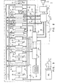
- the system shown very diagrammatically in FIG. 1 can be divided into five main components, namely, the main processor 10, the refresh control logic 11, the memory units serving as buffer memory, that is to say say, the text buffer 12 which stores the text to be displayed and the display instruction buffer 13 which stores various display instructions associated with the text to be displayed and the character generation and display circuits 14 which directly control the scanning of the CRT 15 cathode ray tube.
- the main processor 10 the refresh control logic 11
- the memory units serving as buffer memory that is to say say, the text buffer 12 which stores the text to be displayed and the display instruction buffer 13 which stores various display instructions associated with the text to be displayed
- the character generation and display circuits 14 which directly control the scanning of the CRT 15 cathode ray tube.
- the main processor 10 can be a conventional commercially available microprocessor, the role of which is to receive the input data generally coming from the keystroke by the operator and to store these data in the text buffer 12. It is assumed that when the alpha-numeric information is displayed on the CRT cathode ray tube 15, the operator enters, via the keyboard 16, new characters. To store these characters in the text buffer memory 12, it is first necessary to stop the refresh command of the cathode ray tube. This operation is done using the main processor which generates and maintains a signal on the request stop line 17 and which waits for a response from the refresh control logic 11 on the stop line 18.
- the main microprocessor 10 updates the text buffer memory 12, via the bus 19, in order to store the new characters in their appropriate position; in addition, the processor 10 initializes the display instruction buffer 13, via the bus 20.
- the main microprocessor 10 releases the electronic refresh circuits from their stopped state by suppressing the output from the line request stop 17.
- the apparatus under the control of the display instruction buffer memory carries out an initial scan of the stored data to be displayed, a scan which can be called pre-scan, during which are carried out and stored all tabulation and / or carriage return calculations.
- the display instruction buffer communicates with the refresh control logic 11, along the bus 21, and the refresh control logic 11 communicates with the generation and display of characters 14, by the following connections.
- the refresh control logic 11 activates the line of character segment 21, which allows the character generation and display circuits to form, according to character segments displayed on the cathode-ray tube, a sequence of characters whose coded representations are successively sent from the text buffer memory , by bus 22, to the refresh control logic from which they are sent to the electronic circuits 14, by bus 23.
- the nature of the electronic circuits for generating and displaying characters is not part of the present invention , and, therefore, will not be described further.
- Conventional electronic circuits for generating and displaying character segments for cathode ray tube can be used and can be of the type described in US Pat. No. 3,609,745.
- a signal on line 24 which indicates that the character which has recently been required to be refreshed by the refresh control logic 11 is complete
- a signal on line 25 which indicates that the time reserved for the minimum refresh period has elapsed completely and that the next refresh period should begin.
- the positional data of the displayed alpha-numeric characters are sent from the refresh control logic along the bus 28, and the various character attributes described above are sent from the logic. control command 11 along the bus 29.
- Figure 2 shows the system in more detail shown in very general form in Figure 1.
- the functional units are represented with their logic and are delimited by a broken line; these logic units, which have the same reference as those used in FIG. 1, are the main processor 10, the refresh control logic 11, the text buffer memory 12, the display instruction buffer memory 13, the electronic character generation and display circuits 14 and the CRT cathode ray tube 15.
- the main processor 10 and the refresh control logic 11 share the two fundamental memories of the system, namely, the text buffer 12 and the display instruction buffer 13 so that the processor 10 or the logic 11 can have independent access to each of them.
- the main processor as well as the refresh control logic can modify the context of the display instruction buffer 13.
- only the main processor can modify the content of the text buffer.
- the display instruction buffer 13 comprises an instruction memory 30 which has a width of sixteen bits (or binary pieces of information) which is accessed by a sixteen bit address, by the counter address 31 and the sixteen-bit polarity maintaining register 32 which locks the address until the application of the clock pulse P3 allows the address of register 32 to be sent to the memory of instructions 30 to indicate the next instruction.
- the alpha-numeric text is stored in the text memory 33 of the text buffer 12 in the form of representations of coded alpha-numeric characters each having a width of one byte, memory which is accessed by an address from the sixteen-bit address counter 34 by the polarity maintaining register 35 which also requires a clock pulse P3 to indicate the representation to the next character in memory 33.
- the system of the present invention is controlled by a three-phase clock which generates three non-overlapping pulses, P1, P2 and P3.
- the pulse P1 is used to increment the system firmware counter which will be described in more detail below as well as to time the data entered in the ALU buffer which will also be described in more detail below.
- the P2 pulse is used to load, or increment, or decrement various registers.
- Pulse P3 is used to load the buffer memories from the various registers and address counters.
- the refresh control logic 11, Figure 2 will now be described in more detail.
- the refresh control logic performs the functions associated with finding and executing instructions from the display instruction buffer.
- the refresh control logic operates not only during the refresh cycle but also during the initial cycle during which each of the characters to be displayed is formed. Since the display instruction buffer 13 operates during the initial character formation in a different way from that used during the character refresh cycle, the instructions produced are different, and, consequently, the cooling control logic works differently.
- the refresh control logic 11, FIG. 2 has stored in a permanent memory 36, a large variety of groups of microinstructions arranged so as to control the interaction of the various components of the system represented in FIG.
- memory 36 is a permanent ROS memory of 256 words of forty bits each with which are associated addressing means comprising an 8-bit counter, 37 and an 8-bit polarity maintaining register, 38.
- the address counter and the polarity maintaining register operate in the same way as that used by the means described for address the instruction memory 30 or the text memory 33, that is to say that the application of the clock pulse P3 to the register 38 causes the address applied to the register 38 and which found there maintained, indicates the appropriate microinstruction byte in ROS memory 36.
- ALU 39 logic and arithmetic unit which receives the data by the input buses ALU 40 and 41.
- the exit from the ALU 39 is locked in the 16-bit polarity maintaining register 42 by the application of the clock pulse P1 which causes the data present in the register 42 to be sent on the output bus ALU 43.
- the system further includes a notepad memory 44 in which numerous temporary parameters relating to the displayed text can be stored. For example, in a memory of 8 words at 16 bits each, parameters such as: line spacing, left margin, sub-margin can be stored. All these parameters are necessary to calculate a carriage return, as will be described below.
- a character decoding unit 46 operates to decode or translate the coded representation of the alpha-numeric characters stored in the text buffer into an output transmitted by the bus 23 to the character segment generator 47 which, in turn, generates and transmits by bus 48 to the display circuits 49 of the CRT tube, the signals necessary to activate these circuits so that they plot the alpha-numeric character to display on the CRT tube as a series of segments.
- the input of the coded representation of the character to be displayed from the text memory 33 on the character decoding unit 46 passes through the input bus 41 to reach the ALU 39 from which it is sent to the output bus 43 from which it is loaded into the character code polarity maintaining register 50 from which it is sent to the character decoding unit 46 by an input clock pulse P2.
- a 10-bit horizontal position register 51 keeps track of the escape position.
- the initial horizontal position is stored in the display instruction memory 30.
- the loading of this initial horizontal position in the register 51 is done by transmitting the position on the bus 41 which passes in the ALU 39 and in the output register 42 to then pass on the output bus 43 from which it is loaded in the horizontal position register 51.
- the horizontal position of the character is communicated to the character generator 47, by the bus 28 '.
- the horizontal escape is to be incremented by loading the escape value of the character displayed on the bus 40, by bus 52, and by adding this escape value to the horizontal escape value which was applied in the ALU 39 unit, by buses 53 and 41.
- This updated value then switches back from the unit ALU and its output register 42, via bus 43, in register 51.
- the vertical position register 54 keeps track of the vertical position of the display in a similar manner.
- the initial vertical position is loaded into register 54 in a similar manner to that used to load the horizontal position register 51, that is to say, the initial vertical position is transmitted from the memory 30, via the ALU 39 and the output register 42, to the vertical position register 54.
- the vertical position of the character is communicated to the character generator 47, via the 28 '' bus.
- the unit 46 loads this vertical increment by the bus 41 and the bus 55, into the ALU unit 39 from where it is added to the last vertical position, or position in progress from the generator 54 and passing through the bus 56 and the bus 40 to reach the unit ALU 39 from which the updated value is returned by the output register and the bus 43, to the vertical position register 54 .
- the coded representations of the various character attributes are loaded into the character attribute register 57 at the time. where they should be executed.
- the character attribute register 57 is loaded by the ALU as described previously.
- the register 57 which is a 3-bit register containing the code which determines the character attributes, sends this code by the bus 29 in the register of character segments 47 and to the display circuits 49 of the cathode-ray tube to actuate the latter the required character attribute mode.
- an important aspect of the present invention involves means sensitive to a tabulation code to which we had access to calculate the tabulation position of the next character to be displayed only during the initial cycle during which each is formed. selected characters.
- This function will now be described. We assume that we are in an initial cycle after a change in the information to be displayed and that the coded representations of the characters stored in the text memory 33 are sequentially addressed by the address counter 34 and the register 35 (pre-scan) when the next coded representation is a tabulation code.
- the tabulation code is sent on the bus 41 to pass through the ALU 39 and from there, via the bus 43, into the character decoding unit 46 which, after detection of a tabulation code, transmits a signal representing a special non-graphical code on a special function bus 59 towards the sequence control logic which, in combination with the microinstruction network 36, controls the execution of the instructions in the the present invention. Note that this signal is not differentiated from tabulation codes and other non-graphical codes, such as carriage return codes.
- the sequence control logic 60 then signals to the microinstruction memory 36, by the bus 61, to send the data field of the microinstruction addressed, simultaneously in the ALU 39, by the buses 62 and 40.
- the character decoding unit 46 transmits a 7-bit value specifying the non-graphic code as a tabulation applied to the ALU unit 39, by the buses 63 and 41.
- the input coming from the unit 46 and the input of the microinstructions memory 36, are added to the unit ALU 39 and the result returns via the bus 43 to the microinstructions memory 36 which, via the address counter 37 and the register 38, indicates the sequence of microinstructions then necessary to calculate the tabulation on the next character position.
- the tab rack is considered to include a network of 128 sequentially accessible bytes in which a binary "1" on any bit indicates a particular tab position (the positions being at 1024 bits) at which one will have sequential access during operation.
- the addressing of each bit position is done by incrementing the horizontal position register 51 so as to address each of the 1024 bits.
- the data field of a microinstruction from the memory 36 containing a binary "1" is sent by the bus 40 to the ALU unit 39 where it is combined with the output 53 which indicates the last position of the horizontal position register 51 , on the bus 41.
- the output of the ALU unit 39 is locked in the register 42 and is then transferred by the bus 43 in order to be loaded in the horizontal position register 51 which ends the operation of increment which consists of loading 10 bits into register 51.
- the 7 higher order bits of register 51 indicate in tabulation rack 64 the first byte whose 8 bits are loaded in one of the 8 selection means 65, by the bus 66.
- Each of the 8 bits is then addressed by the 3 lower order bits of the register 51, by the bus 67.
- the process of incrementing the horizontal position register 51 described previously makes these 3 lower order bits address sequentially each of the 8 bits d u selected means 65.
- the incrementation process causes each of the following bytes of the tab rack 64 to be addressed until a bit is found " 1 "indicating a tab.
- the selection means 65 transmits a tabulation location signal on the line 68 in the direction of the sequence control logic 60 which, in turn, transmits a signal to the ROS microinstruction memory 36 which, at its turn, sends an instruction to the ALU 39 from which we will obtain in the horizontal position register 51 the value which represents the tabulated position to be stored in the display instruction memory 30 as position "go to ", for example,” GO TO HORIZONTAL EXHAUST 95 ".
- the unit 46 transmits a signal which indicates its state of carriage return to the unit ALU 39, via the buses 63 and 41.
- the outputs coming from the unit 46 and from the memory of microinstructions 36 in the unit ALU 39 result on the bus 43 in a single output which is returned to the microinstruction memory 36 which, by the address counter 37 and the register 38, indicates the sequence of microinstructions stored in the memory 36 then necessary to proceed to the carriage return code .
- the sequence involves access to the line spacing data stored in the notepad memory 44 and the transmission of this data on the bus 41 in the direction of the ALU unit 39 where it is combined with the input corresponding to the last vertical position of the carriage coming from the vertical position register 54, by the buses 56 and 40.
- the output coming from the ALU 39 is transmitted on the bus 43 and, then, is reloaded in the vertical position register 54 as new vertical position of the support.
- the left margin position is removed from the notepad memory 44 and passes by the bus 41 and by the ALU unit 39 to be loaded into the horizontal position register 51 If there should not be a withdrawal, this position represents the initial carriage return position, and the micro-instruction memory ROS 36 in turn transmits an instruction in the unit ALU 39 which finally supplies the values of the register of vertical positions 54 and the horizontal position register 51, values which represent the position of the carriage return to be stored in the display instruction memory 30 as the "go to" position, for example "GO TO LINE 45, EXHAUST POSITION 15".
- the line on which the carriage return is made has an initial point indented. Since this line is indented, the number of indentation levels is stored in the notepad memory 44. In addition, for the particular line where there is indentation, a tabulation bit "1" is stored at each position of the respective bit of the tab rack 64 until the withdrawal position is reached. Then, using the sequence of tabulation detection operations described previously, we go through each of the tabulation positions. If for example, the withdrawal corresponds to 5 escape positions from the left margin, 5 consecutive "1" bits are stored for the particular line in the tab rack 64 and the tab search routine described is executed 5 times .
- the memory of microinstructions After communication to the memory of microinstructions 36, of the signal corresponding to the fifth tabulation on line 68 in the direction of command 60, as previously described, the memory of microinstructions transmits an instruction in the unit ALU 39 which finally provides the values of the horizontal position register 51 and of the vertical position register 54 stored in the display instruction memory 30 as the "go to" position, for example, "GO TO LINE 45, EXHAUST POSITION, HORIZONTAL 20 ".
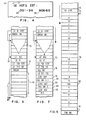
- the display instruction buffer When the display instruction buffer is loaded as shown in Figure 6, it transmits a series of instructions which control the refresh command 11 ( Figure 1 or Figure 2) for a pre-sweep operation.
- the initial instruction in the "LD DI STRT" display instruction buffer simply causes the instruction (in section 70) to be loaded into the instruction sequence which is constant for any display operation, these instructions can be, for example, framing instructions.
- the instruction "LD VRT” causes the loading of the vertical position of the character 72 in the vertical position register 54, as described previously.
- the instruction LD TSB STRT and the following instruction "LD TSB ND” identify the instructions TSB STRT (73) and TSB ND (74) in the buffer instruction sequence ( Figure 5).
- PRCN initiates the pre-scan operation using the apparatus described previously with reference to Figure 2 to scan the sequence of alpha-numeric data and positions in the text buffer 12 ( Figure 5) and to store in overload (OVRWT) the sequence of instructions indicated in the display instruction buffer 13 (FIG. 6) among which are the pre-scan instruction itself as well as any other instructions 75.
- the display instruction buffer 13 is found to have the sequence of instructions illustrated in FIG. 7 to which we will now refer for the repetitive refresh cycle of the 'equipment.
- the pre-sweep instruction itself is overloaded by the instruction 76, Figure 7, namely the "Beam position" (POS BM) instruction.
- the next instruction is the "LD TXT PTR" instruction.
- the pointer 77 ( Figure 5) is fixed so as to indicate the first alpha-numeric character "L” and the characters of the text buffer 12 are sequenced as described previously with reference to Figure 3 by successively sending these characters to the ROS character decoding memory 46 ( Figure 2) while a quiescent pulse is applied to the generator of character segments 47, via line 77, coming from of the sequence logic 60 in order to maintain the display in the idle state, that is to say of no display, during the pre-sweep operation.
- a display start instruction (ST RT DSP) 78 is written in the display instruction buffer to be used during the refresh cycle ( Figure 7) at the point which coincides with the sequencing of characters from the text buffer 12 ( Figure 5).
- ST RT DSP display start instruction
- the coded representation of the characters is sequenced in the character decoding memory 46 in the manner described previously, and the system decodes these characters to finally give an output transmitted on the bus 23 to the segment generator. character 47.
- the generator 47 and, consequently, the electronic display circuits CRT 49 are in the rest state following the signal present on the line 77, no alpha-numeric character n 'is displayed during this pre-sweep cycle.
- the character code 79 from the text buffer ( Figure 5) "(CR)" indicates a carriage return.
- the system calculates the position of the carriage return which is the position of the character "0" 80 in the display of Figure 4
- This carriage return sequence involves access to the line spacing data present in the notepad memory 40 and the transmission of data via the ALU unit 39 where they are added to the last vertical position of carriage from the position register 54 which is then updated to give the new vertical position.
- the left margin position is removed from the notepad memory 44 and sent to the ALU unit 39 where it is combined with the number of withdrawals also stored in the memory 44 in order to to calculate the position of final withdrawal of the character "0" 80 ( Figure 4).
- This updated horizontal carriage return value is loaded into the horizontal position register 51.
- the instruction 81 POS BM XY
- This instruction in fact, tells the cathode ray tube bundle to pass to a defined position which is determined by the updated vertical and horizontal positions then loaded into registers 54 and 51.
- the characters "OUT-96" are sequenced in the character decoding unit 46 in the manner previously described while the quiescence signal is always maintained on line 77; after which, the character code "(TAB)" is decoded in the unit 46 ( Figure 2).
- This operation triggers the tabulation operation described previously with reference to Figure 2 in which, using the tab rack 64 and the selection means 65, the next tab position is calculated and its value is stored in the position register horizontal 51.
- the instruction 84 is stored in the display instruction buffer 13 (FIG. 7) to be used then during the refresh cycle.
- the electronic display circuits bring the beam CRT to the horizontal position which is contained in the horizontal position register 51 after the tabulation calculation has been carried out. This position is, of course, the horizontal position of the alpha-numeric character N 83 ( Figure 4).
- instruction 85 "STRT DSP" is written to the display instruction memory for use in the refresh cycle ( Figure 7).
- the instruction "POS BM" 76 causes the beam CRT to be placed at the position corresponding to the first character "L" 72.
- the text pointer 77 ( Figure 5) is loaded by the buffer memory display instructions so that it indicates a stored representation of the character "L”.
- the display instruction buffer sends the "STRT DSP" instruction 78 which causes a segment signal to replace the quiesce signal on bus 77 69 and is sent to the display electronics.
- CRT and the character segment generator ( Figure 2) which results in sequencing the series of characters from the text storage buffer 12, in unit 46.
- the ROS character decoding unit 46 sends to the character code generator 47 and to the electronic display circuits CRT 49, through the buffer memory 23, the signals necessary to actuate the electronic display circuits so that they trace the alpha-numeric character to be displayed on the CRT tube according to a series of segments. This results in displaying the first line on the CRT cathode ray tube in Figure 4.
- the unit 46 detects the carriage return code (CR) 79 from the text buffer 12, which has as a result that a special non-graphical code signal on the special function bus 57 is applied to the sequence control logic 60, and that this unit 46 sends at the same time on the bus 63 a 7-bit value which specifies the non-graphic code as being a carriage return code applied to the unit ALU 39.
- These two operations cause the return of an output on the bus 43 in the direction of the microinstruction memory 36, which, in turn, sends an instruction, by the unit ALU 39, to the display instruction buffer memory 13 in order to have access in this memory to the following instruction 81 which consists in placing the beam at the indicated carriage return position which has been previously calculated and recorded.
- the instruction 82 originating from the display instruction buffer 13 begins the display at the carriage return position 80 (FIG. 4) and the character sequence "YES- 96 "coming from the text storage buffer 12 passes into the unit 46 as previously described to finally cause the display of the corresponding alpha-numeric characters, as shown in Figure 4.
- the tab code “Tab” 82 from the text buffer 12 is sent to the ROS character decoding unit 46. Again, a signal representing a special function is sent on the special function bus 59 in the direction of the sequence control logic 60 while, at the same time, the character decoding unit 46 transmits a signal indicating the tabulation function. to the ALU unit 39, via the bus 63. It follows that the ALU unit 39 addresses, in the memory of microinstructions 36, an instruction which, in turn, again through the unit ALU 39, indicates in the buffer memory 13 the instruction 34 which brings the beam to the tabulation position previously calculated which corresponds to the position 83 in the display represented in FIG. 4. At this stage, the coded representations of the characters "NO -60 "are sequenced in the ROS unit 46 after the instruction of" STRT DSP "85 ( Figure 7) and the rest of the second line” NON-60 "is displayed on the CRT tube of Figure 4.
Landscapes
- Engineering & Computer Science (AREA)
- Theoretical Computer Science (AREA)
- Physics & Mathematics (AREA)
- General Physics & Mathematics (AREA)
- Remote Sensing (AREA)
- Computer Hardware Design (AREA)
- Radar, Positioning & Navigation (AREA)
- Health & Medical Sciences (AREA)
- Artificial Intelligence (AREA)
- Audiology, Speech & Language Pathology (AREA)
- Computational Linguistics (AREA)
- General Health & Medical Sciences (AREA)
- General Engineering & Computer Science (AREA)
- Controls And Circuits For Display Device (AREA)
Applications Claiming Priority (2)
| Application Number | Priority Date | Filing Date | Title |
|---|---|---|---|
| US47435 | 1979-06-11 | ||
| US06/047,435 US4247853A (en) | 1979-06-11 | 1979-06-11 | Alphanumeric CRT display system with means for storing positional data calculated during an initial scan |
Publications (3)
| Publication Number | Publication Date |
|---|---|
| EP0020985A2 true EP0020985A2 (de) | 1981-01-07 |
| EP0020985A3 EP0020985A3 (en) | 1982-03-03 |
| EP0020985B1 EP0020985B1 (de) | 1984-10-17 |
Family
ID=21948963
Family Applications (1)
| Application Number | Title | Priority Date | Filing Date |
|---|---|---|---|
| EP80102583A Expired EP0020985B1 (de) | 1979-06-11 | 1980-05-09 | Textbearbeitungssystem mit einer Kathodenstrahlanzeige |
Country Status (4)
| Country | Link |
|---|---|
| US (1) | US4247853A (de) |
| EP (1) | EP0020985B1 (de) |
| JP (1) | JPS55166686A (de) |
| DE (1) | DE3069447D1 (de) |
Cited By (3)
| Publication number | Priority date | Publication date | Assignee | Title |
|---|---|---|---|---|
| FR2556869A1 (fr) * | 1983-12-14 | 1985-06-21 | Int Computers Ltd | Dispositif de tabulation pour visuel de terminal portatif |
| EP0115947A3 (en) * | 1983-01-28 | 1986-06-11 | Fujitsu Limited | Character insertion means for word processing systems |
| EP0292726A3 (en) * | 1987-05-26 | 1989-06-14 | International Business Machines Corporation | Correction buffer |
Families Citing this family (8)
| Publication number | Priority date | Publication date | Assignee | Title |
|---|---|---|---|---|
| US4450534A (en) * | 1981-05-14 | 1984-05-22 | Texas Instruments Incorporated | Multiprocessor with dedicated display |
| JPS57151386A (en) * | 1981-03-16 | 1982-09-18 | Silver Seiko Ltd | Typewriter |
| JPS57173886A (en) * | 1981-04-21 | 1982-10-26 | Tokyo Shibaura Electric Co | Crt display device |
| US4623147A (en) * | 1983-09-20 | 1986-11-18 | General Computer Company | Process for displaying a plurality of objects on a video screen |
| DE3682880D1 (de) * | 1985-11-28 | 1992-01-23 | Canon Kk | Dokumentverarbeitungssystem. |
| JPS62198893A (ja) * | 1986-02-26 | 1987-09-02 | 横河電機株式会社 | グラフイツク表示方法 |
| US7145581B2 (en) * | 2002-08-30 | 2006-12-05 | Intel Corporation | Selectively updating pulse width modulated waveforms while driving pixels |
| US20060092147A1 (en) * | 2004-11-03 | 2006-05-04 | Roberts Ben D | Pulse width modulation technique and apparatus for a display array |
Family Cites Families (5)
| Publication number | Priority date | Publication date | Assignee | Title |
|---|---|---|---|---|
| US3437869A (en) * | 1965-11-01 | 1969-04-08 | Ibm | Display apparatus |
| US3540032A (en) * | 1968-01-12 | 1970-11-10 | Ibm | Display system using cathode ray tube deflection yoke non-linearity to obtain curved strokes |
| US3618032A (en) * | 1968-12-09 | 1971-11-02 | Ibm | Automatic data composing, editing and formatting system |
| US3816823A (en) * | 1972-09-28 | 1974-06-11 | Redactron Corp | Character display system with tabbing function |
| GB1434777A (en) * | 1973-01-10 | 1976-05-05 | Siemens Ag | Character representation systems |
-
1979
- 1979-06-11 US US06/047,435 patent/US4247853A/en not_active Expired - Lifetime
-
1980
- 1980-04-09 JP JP4581280A patent/JPS55166686A/ja active Granted
- 1980-05-09 EP EP80102583A patent/EP0020985B1/de not_active Expired
- 1980-05-09 DE DE8080102583T patent/DE3069447D1/de not_active Expired
Cited By (3)
| Publication number | Priority date | Publication date | Assignee | Title |
|---|---|---|---|---|
| EP0115947A3 (en) * | 1983-01-28 | 1986-06-11 | Fujitsu Limited | Character insertion means for word processing systems |
| FR2556869A1 (fr) * | 1983-12-14 | 1985-06-21 | Int Computers Ltd | Dispositif de tabulation pour visuel de terminal portatif |
| EP0292726A3 (en) * | 1987-05-26 | 1989-06-14 | International Business Machines Corporation | Correction buffer |
Also Published As
| Publication number | Publication date |
|---|---|
| US4247853A (en) | 1981-01-27 |
| JPS6126072B2 (de) | 1986-06-18 |
| JPS55166686A (en) | 1980-12-25 |
| DE3069447D1 (en) | 1984-11-22 |
| EP0020985A3 (en) | 1982-03-03 |
| EP0020985B1 (de) | 1984-10-17 |
Similar Documents
| Publication | Publication Date | Title |
|---|---|---|
| EP0020932B1 (de) | System zur Verarbeitung und Anzeige von Texten | |
| EP0020985B1 (de) | Textbearbeitungssystem mit einer Kathodenstrahlanzeige | |
| JPWO2019241428A5 (de) | ||
| JPS60245083A (ja) | 電子辞書 | |
| FR2560412A1 (fr) | Appareil de traitement de donnees | |
| CN112487334A (zh) | 用于前端页面语言翻译的方法、装置、计算机设备和介质 | |
| CN114924703B (zh) | 一种分辨率和刷新率的切换方法、装置及介质 | |
| GB2247763A (en) | Word processor having a word frequency count unit | |
| CN100349203C (zh) | 支持比例字形的同屏显示装置及其方法 | |
| FR2637996A1 (fr) | Circuit pour executer a grande vitesse certaines operations booleennes de traitement de trame pour affichage sur l'ecran d'une station de travail | |
| EP4647957A1 (de) | Automatisierte erzeugung von inhalten in markenstimme durch maschinelles lernen | |
| JP2001117574A (ja) | 文書読み上げ装置および文書読み上げ方法ならびに文書読み上げプログラムを記録する記録媒体 | |
| JPS60176137A (ja) | 文章作成機 | |
| JPH0346857B2 (de) | ||
| JP2019109703A (ja) | 文書検索装置、文書検索方法、及びプログラム | |
| JP2973520B2 (ja) | 電子文書編集装置における表示方式 | |
| CN120296268A (zh) | 一种h5页面交互方法、可读存储介质以及电子设备 | |
| JPS5935960A (ja) | ハ−ドコピ−制御装置 | |
| FR2583560A1 (fr) | Procede d'affichage de symboles et dispositif de mise en oeuvre de ce procede | |
| JP3067083B2 (ja) | 文書入力装置 | |
| JP3062052B2 (ja) | 電子シート内計算式自動生成装置 | |
| JPS59106035A (ja) | 文書処理装置の振仮名付加方式 | |
| JP2808105B2 (ja) | フオント描画装置 | |
| JPH0566757A (ja) | フオント生成装置 | |
| JPS59188723A (ja) | 文字処理装置 |
Legal Events
| Date | Code | Title | Description |
|---|---|---|---|
| PUAI | Public reference made under article 153(3) epc to a published international application that has entered the european phase |
Free format text: ORIGINAL CODE: 0009012 |
|
| AK | Designated contracting states |
Designated state(s): DE FR GB |
|
| 17P | Request for examination filed |
Effective date: 19810828 |
|
| PUAL | Search report despatched |
Free format text: ORIGINAL CODE: 0009013 |
|
| AK | Designated contracting states |
Designated state(s): DE FR GB |
|
| GRAA | (expected) grant |
Free format text: ORIGINAL CODE: 0009210 |
|
| AK | Designated contracting states |
Designated state(s): DE FR GB |
|
| REF | Corresponds to: |
Ref document number: 3069447 Country of ref document: DE Date of ref document: 19841122 |
|
| PLBE | No opposition filed within time limit |
Free format text: ORIGINAL CODE: 0009261 |
|
| 26N | No opposition filed | ||
| PGFP | Annual fee paid to national office [announced via postgrant information from national office to epo] |
Ref country code: GB Payment date: 19900404 Year of fee payment: 11 |
|
| PGFP | Annual fee paid to national office [announced via postgrant information from national office to epo] |
Ref country code: FR Payment date: 19900424 Year of fee payment: 11 |
|
| PGFP | Annual fee paid to national office [announced via postgrant information from national office to epo] |
Ref country code: DE Payment date: 19900529 Year of fee payment: 11 |
|
| PG25 | Lapsed in a contracting state [announced via postgrant information from national office to epo] |
Ref country code: GB Effective date: 19910509 |
|
| GBPC | Gb: european patent ceased through non-payment of renewal fee | ||
| PG25 | Lapsed in a contracting state [announced via postgrant information from national office to epo] |
Ref country code: FR Effective date: 19920131 |
|
| PG25 | Lapsed in a contracting state [announced via postgrant information from national office to epo] |
Ref country code: DE Effective date: 19920303 |
|
| REG | Reference to a national code |
Ref country code: FR Ref legal event code: ST |