EP0020985A2 - Text processing system with CRT display - Google Patents
Text processing system with CRT display Download PDFInfo
- Publication number
- EP0020985A2 EP0020985A2 EP80102583A EP80102583A EP0020985A2 EP 0020985 A2 EP0020985 A2 EP 0020985A2 EP 80102583 A EP80102583 A EP 80102583A EP 80102583 A EP80102583 A EP 80102583A EP 0020985 A2 EP0020985 A2 EP 0020985A2
- Authority
- EP
- European Patent Office
- Prior art keywords
- character
- memory
- tabulation
- carriage return
- characters
- Prior art date
- Legal status (The legal status is an assumption and is not a legal conclusion. Google has not performed a legal analysis and makes no representation as to the accuracy of the status listed.)
- Granted
Links
Images

Classifications
-
- G—PHYSICS
- G06—COMPUTING; CALCULATING OR COUNTING
- G06F—ELECTRIC DIGITAL DATA PROCESSING
- G06F40/00—Handling natural language data
- G06F40/10—Text processing
- G06F40/166—Editing, e.g. inserting or deleting
- G06F40/183—Tabulation, i.e. one-dimensional positioning
-
- G—PHYSICS
- G09—EDUCATION; CRYPTOGRAPHY; DISPLAY; ADVERTISING; SEALS
- G09G—ARRANGEMENTS OR CIRCUITS FOR CONTROL OF INDICATING DEVICES USING STATIC MEANS TO PRESENT VARIABLE INFORMATION
- G09G1/00—Control arrangements or circuits, of interest only in connection with cathode-ray tube indicators; General aspects or details, e.g. selection emphasis on particular characters, dashed line or dotted line generation; Preprocessing of data
Definitions
- the present invention relates to text processing and display systems and, more particularly, to a cathode ray tube display (CRT) word processing system in which an alpha-numeric data block which can be for example an entire page with display must be maintained on the CRT display tube.
- CRT cathode ray tube display
- the preparation of a business document often involves typing and editing several drafts of the document before it is complete, correct and presented in a form that is easily understandable and aesthetic to the eye.
- the stages of preparing a printed document in its final form often require: (1) typing a draft from rough data, dictation or notes; (2) erasures, insertions of restructurings and corrections by an editor; (3) recaps using the edited draft as a source of information; (4) re-editing to ensure corrections and obtain aesthetic perfection; (5) re-types as required by step (4) and re-edition to obtain a correct final copy.
- this information must be re-read and possibly edited to ensure that it is correct and, each time it is edited, it must be re-typed. .
- This process is extremely long, because there is a loss of time at the level of the secretary, since there is rewrite and at the level of the editor, since there is re-edition.
- the prior art proposes several devices to reduce the loss of time due to the re-typing and re-edition of business documents.
- a traditional approach of the prior art consists in recording the characters struck on a second support, for example a magnetic support, which is selectively used by the typist to control the typewriter so that the latter automatically prints the information contained as output. in the first draft with changes to the edition.
- this traditional approach has been replaced by word processing systems which use a cathode ray tube display (CRT), or similar devices, which display the information entered for example by keyboard in the input terminal of a word processor. The information entered is displayed and the operator can make corrections to the data thus displayed. These corrections entail, of course, the entry of new data, the deletion of existing data or the insertion of new data.
- proportional spacing that is, in which the alpha-numeric characters have a variable width.
- proportional spacing systems instead of having about one hundred possible character positions per display line, there are more than seven hundred and fifty possible escape positions which must be taken into account when calculating character positions. displayed. It follows that the operations of data processing required to ensure each refresh cycle, are even more complex and time consuming.
- One approach used to minimize data processing time during refresh cycles is to structure (format) a matrix memory so that it has all of the possible character positions from the CRT display and to store at each character position sufficient data to identify at this position the character or the absence of a character as well as its associated attribute. While this approach offers an acceptable solution to the refresh time required and to the system employing relatively small displays of the order of 1 to 5 lines, it is cumbersome and expensive in processing and displaying text processing systems. whole pages. The system requires approximately one byte of data at each storage position, or approximately 100 x 70, that is, 7000 bytes of data on each entire page displayed.
- the object of the present invention is therefore a word processing system with display of alpha-numeric data in the form of whole pages having a refresh rate which prevents the display from blinking while using a storage capacity reduced to a minimum.
- a cathode-ray tube display system comprising position deflection means for moving the beam of the cathode-ray tube to a series of positions selected with reference to a first and a second coordinate axes in response to position signals, position means for generating these position signals, character definition means sensitive to the signals representing a character selected to control the deflection of the beam according to a configuration representing a selected character and for modulating the intensity of the beam on this configuration in order to define the character, and means for generating the signals representing a selected character and for applying them to the character definition means.
- the system includes storage means for sequentially storing the coded representations of the selected characters to be displayed and the tab and carriage return codes of the displayed characters.
- the position means for generating the position signals comprise: calculation means which, in response to a tabulation code to which one has access, calculate the tabulation position of the next character to be displayed relative to the first coordinate axis only during the initial cycle during which each of the selected characters is formed, a memory for storing each calculated tab position, and access means operating only during refresh cycles to have access to the previously calculated tab position, and stored in said memory, in response to the corresponding tabulation code.
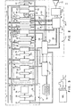
- the system shown very diagrammatically in FIG. 1 can be divided into five main components, namely, the main processor 10, the refresh control logic 11, the memory units serving as buffer memory, that is to say say, the text buffer 12 which stores the text to be displayed and the display instruction buffer 13 which stores various display instructions associated with the text to be displayed and the character generation and display circuits 14 which directly control the scanning of the CRT 15 cathode ray tube.
- the main processor 10 the refresh control logic 11
- the memory units serving as buffer memory that is to say say, the text buffer 12 which stores the text to be displayed and the display instruction buffer 13 which stores various display instructions associated with the text to be displayed
- the character generation and display circuits 14 which directly control the scanning of the CRT 15 cathode ray tube.
- the main processor 10 can be a conventional commercially available microprocessor, the role of which is to receive the input data generally coming from the keystroke by the operator and to store these data in the text buffer 12. It is assumed that when the alpha-numeric information is displayed on the CRT cathode ray tube 15, the operator enters, via the keyboard 16, new characters. To store these characters in the text buffer memory 12, it is first necessary to stop the refresh command of the cathode ray tube. This operation is done using the main processor which generates and maintains a signal on the request stop line 17 and which waits for a response from the refresh control logic 11 on the stop line 18.
- the main microprocessor 10 updates the text buffer memory 12, via the bus 19, in order to store the new characters in their appropriate position; in addition, the processor 10 initializes the display instruction buffer 13, via the bus 20.
- the main microprocessor 10 releases the electronic refresh circuits from their stopped state by suppressing the output from the line request stop 17.
- the apparatus under the control of the display instruction buffer memory carries out an initial scan of the stored data to be displayed, a scan which can be called pre-scan, during which are carried out and stored all tabulation and / or carriage return calculations.
- the display instruction buffer communicates with the refresh control logic 11, along the bus 21, and the refresh control logic 11 communicates with the generation and display of characters 14, by the following connections.
- the refresh control logic 11 activates the line of character segment 21, which allows the character generation and display circuits to form, according to character segments displayed on the cathode-ray tube, a sequence of characters whose coded representations are successively sent from the text buffer memory , by bus 22, to the refresh control logic from which they are sent to the electronic circuits 14, by bus 23.
- the nature of the electronic circuits for generating and displaying characters is not part of the present invention , and, therefore, will not be described further.
- Conventional electronic circuits for generating and displaying character segments for cathode ray tube can be used and can be of the type described in US Pat. No. 3,609,745.
- a signal on line 24 which indicates that the character which has recently been required to be refreshed by the refresh control logic 11 is complete
- a signal on line 25 which indicates that the time reserved for the minimum refresh period has elapsed completely and that the next refresh period should begin.
- the positional data of the displayed alpha-numeric characters are sent from the refresh control logic along the bus 28, and the various character attributes described above are sent from the logic. control command 11 along the bus 29.
- Figure 2 shows the system in more detail shown in very general form in Figure 1.
- the functional units are represented with their logic and are delimited by a broken line; these logic units, which have the same reference as those used in FIG. 1, are the main processor 10, the refresh control logic 11, the text buffer memory 12, the display instruction buffer memory 13, the electronic character generation and display circuits 14 and the CRT cathode ray tube 15.
- the main processor 10 and the refresh control logic 11 share the two fundamental memories of the system, namely, the text buffer 12 and the display instruction buffer 13 so that the processor 10 or the logic 11 can have independent access to each of them.
- the main processor as well as the refresh control logic can modify the context of the display instruction buffer 13.
- only the main processor can modify the content of the text buffer.
- the display instruction buffer 13 comprises an instruction memory 30 which has a width of sixteen bits (or binary pieces of information) which is accessed by a sixteen bit address, by the counter address 31 and the sixteen-bit polarity maintaining register 32 which locks the address until the application of the clock pulse P3 allows the address of register 32 to be sent to the memory of instructions 30 to indicate the next instruction.
- the alpha-numeric text is stored in the text memory 33 of the text buffer 12 in the form of representations of coded alpha-numeric characters each having a width of one byte, memory which is accessed by an address from the sixteen-bit address counter 34 by the polarity maintaining register 35 which also requires a clock pulse P3 to indicate the representation to the next character in memory 33.
- the system of the present invention is controlled by a three-phase clock which generates three non-overlapping pulses, P1, P2 and P3.
- the pulse P1 is used to increment the system firmware counter which will be described in more detail below as well as to time the data entered in the ALU buffer which will also be described in more detail below.
- the P2 pulse is used to load, or increment, or decrement various registers.
- Pulse P3 is used to load the buffer memories from the various registers and address counters.
- the refresh control logic 11, Figure 2 will now be described in more detail.
- the refresh control logic performs the functions associated with finding and executing instructions from the display instruction buffer.
- the refresh control logic operates not only during the refresh cycle but also during the initial cycle during which each of the characters to be displayed is formed. Since the display instruction buffer 13 operates during the initial character formation in a different way from that used during the character refresh cycle, the instructions produced are different, and, consequently, the cooling control logic works differently.
- the refresh control logic 11, FIG. 2 has stored in a permanent memory 36, a large variety of groups of microinstructions arranged so as to control the interaction of the various components of the system represented in FIG.
- memory 36 is a permanent ROS memory of 256 words of forty bits each with which are associated addressing means comprising an 8-bit counter, 37 and an 8-bit polarity maintaining register, 38.
- the address counter and the polarity maintaining register operate in the same way as that used by the means described for address the instruction memory 30 or the text memory 33, that is to say that the application of the clock pulse P3 to the register 38 causes the address applied to the register 38 and which found there maintained, indicates the appropriate microinstruction byte in ROS memory 36.
- ALU 39 logic and arithmetic unit which receives the data by the input buses ALU 40 and 41.
- the exit from the ALU 39 is locked in the 16-bit polarity maintaining register 42 by the application of the clock pulse P1 which causes the data present in the register 42 to be sent on the output bus ALU 43.
- the system further includes a notepad memory 44 in which numerous temporary parameters relating to the displayed text can be stored. For example, in a memory of 8 words at 16 bits each, parameters such as: line spacing, left margin, sub-margin can be stored. All these parameters are necessary to calculate a carriage return, as will be described below.
- a character decoding unit 46 operates to decode or translate the coded representation of the alpha-numeric characters stored in the text buffer into an output transmitted by the bus 23 to the character segment generator 47 which, in turn, generates and transmits by bus 48 to the display circuits 49 of the CRT tube, the signals necessary to activate these circuits so that they plot the alpha-numeric character to display on the CRT tube as a series of segments.
- the input of the coded representation of the character to be displayed from the text memory 33 on the character decoding unit 46 passes through the input bus 41 to reach the ALU 39 from which it is sent to the output bus 43 from which it is loaded into the character code polarity maintaining register 50 from which it is sent to the character decoding unit 46 by an input clock pulse P2.
- a 10-bit horizontal position register 51 keeps track of the escape position.
- the initial horizontal position is stored in the display instruction memory 30.
- the loading of this initial horizontal position in the register 51 is done by transmitting the position on the bus 41 which passes in the ALU 39 and in the output register 42 to then pass on the output bus 43 from which it is loaded in the horizontal position register 51.
- the horizontal position of the character is communicated to the character generator 47, by the bus 28 '.
- the horizontal escape is to be incremented by loading the escape value of the character displayed on the bus 40, by bus 52, and by adding this escape value to the horizontal escape value which was applied in the ALU 39 unit, by buses 53 and 41.
- This updated value then switches back from the unit ALU and its output register 42, via bus 43, in register 51.
- the vertical position register 54 keeps track of the vertical position of the display in a similar manner.
- the initial vertical position is loaded into register 54 in a similar manner to that used to load the horizontal position register 51, that is to say, the initial vertical position is transmitted from the memory 30, via the ALU 39 and the output register 42, to the vertical position register 54.
- the vertical position of the character is communicated to the character generator 47, via the 28 '' bus.
- the unit 46 loads this vertical increment by the bus 41 and the bus 55, into the ALU unit 39 from where it is added to the last vertical position, or position in progress from the generator 54 and passing through the bus 56 and the bus 40 to reach the unit ALU 39 from which the updated value is returned by the output register and the bus 43, to the vertical position register 54 .
- the coded representations of the various character attributes are loaded into the character attribute register 57 at the time. where they should be executed.
- the character attribute register 57 is loaded by the ALU as described previously.
- the register 57 which is a 3-bit register containing the code which determines the character attributes, sends this code by the bus 29 in the register of character segments 47 and to the display circuits 49 of the cathode-ray tube to actuate the latter the required character attribute mode.
- an important aspect of the present invention involves means sensitive to a tabulation code to which we had access to calculate the tabulation position of the next character to be displayed only during the initial cycle during which each is formed. selected characters.
- This function will now be described. We assume that we are in an initial cycle after a change in the information to be displayed and that the coded representations of the characters stored in the text memory 33 are sequentially addressed by the address counter 34 and the register 35 (pre-scan) when the next coded representation is a tabulation code.
- the tabulation code is sent on the bus 41 to pass through the ALU 39 and from there, via the bus 43, into the character decoding unit 46 which, after detection of a tabulation code, transmits a signal representing a special non-graphical code on a special function bus 59 towards the sequence control logic which, in combination with the microinstruction network 36, controls the execution of the instructions in the the present invention. Note that this signal is not differentiated from tabulation codes and other non-graphical codes, such as carriage return codes.
- the sequence control logic 60 then signals to the microinstruction memory 36, by the bus 61, to send the data field of the microinstruction addressed, simultaneously in the ALU 39, by the buses 62 and 40.
- the character decoding unit 46 transmits a 7-bit value specifying the non-graphic code as a tabulation applied to the ALU unit 39, by the buses 63 and 41.
- the input coming from the unit 46 and the input of the microinstructions memory 36, are added to the unit ALU 39 and the result returns via the bus 43 to the microinstructions memory 36 which, via the address counter 37 and the register 38, indicates the sequence of microinstructions then necessary to calculate the tabulation on the next character position.
- the tab rack is considered to include a network of 128 sequentially accessible bytes in which a binary "1" on any bit indicates a particular tab position (the positions being at 1024 bits) at which one will have sequential access during operation.
- the addressing of each bit position is done by incrementing the horizontal position register 51 so as to address each of the 1024 bits.
- the data field of a microinstruction from the memory 36 containing a binary "1" is sent by the bus 40 to the ALU unit 39 where it is combined with the output 53 which indicates the last position of the horizontal position register 51 , on the bus 41.
- the output of the ALU unit 39 is locked in the register 42 and is then transferred by the bus 43 in order to be loaded in the horizontal position register 51 which ends the operation of increment which consists of loading 10 bits into register 51.
- the 7 higher order bits of register 51 indicate in tabulation rack 64 the first byte whose 8 bits are loaded in one of the 8 selection means 65, by the bus 66.
- Each of the 8 bits is then addressed by the 3 lower order bits of the register 51, by the bus 67.
- the process of incrementing the horizontal position register 51 described previously makes these 3 lower order bits address sequentially each of the 8 bits d u selected means 65.
- the incrementation process causes each of the following bytes of the tab rack 64 to be addressed until a bit is found " 1 "indicating a tab.
- the selection means 65 transmits a tabulation location signal on the line 68 in the direction of the sequence control logic 60 which, in turn, transmits a signal to the ROS microinstruction memory 36 which, at its turn, sends an instruction to the ALU 39 from which we will obtain in the horizontal position register 51 the value which represents the tabulated position to be stored in the display instruction memory 30 as position "go to ", for example,” GO TO HORIZONTAL EXHAUST 95 ".
- the unit 46 transmits a signal which indicates its state of carriage return to the unit ALU 39, via the buses 63 and 41.
- the outputs coming from the unit 46 and from the memory of microinstructions 36 in the unit ALU 39 result on the bus 43 in a single output which is returned to the microinstruction memory 36 which, by the address counter 37 and the register 38, indicates the sequence of microinstructions stored in the memory 36 then necessary to proceed to the carriage return code .
- the sequence involves access to the line spacing data stored in the notepad memory 44 and the transmission of this data on the bus 41 in the direction of the ALU unit 39 where it is combined with the input corresponding to the last vertical position of the carriage coming from the vertical position register 54, by the buses 56 and 40.
- the output coming from the ALU 39 is transmitted on the bus 43 and, then, is reloaded in the vertical position register 54 as new vertical position of the support.
- the left margin position is removed from the notepad memory 44 and passes by the bus 41 and by the ALU unit 39 to be loaded into the horizontal position register 51 If there should not be a withdrawal, this position represents the initial carriage return position, and the micro-instruction memory ROS 36 in turn transmits an instruction in the unit ALU 39 which finally supplies the values of the register of vertical positions 54 and the horizontal position register 51, values which represent the position of the carriage return to be stored in the display instruction memory 30 as the "go to" position, for example "GO TO LINE 45, EXHAUST POSITION 15".
- the line on which the carriage return is made has an initial point indented. Since this line is indented, the number of indentation levels is stored in the notepad memory 44. In addition, for the particular line where there is indentation, a tabulation bit "1" is stored at each position of the respective bit of the tab rack 64 until the withdrawal position is reached. Then, using the sequence of tabulation detection operations described previously, we go through each of the tabulation positions. If for example, the withdrawal corresponds to 5 escape positions from the left margin, 5 consecutive "1" bits are stored for the particular line in the tab rack 64 and the tab search routine described is executed 5 times .
- the memory of microinstructions After communication to the memory of microinstructions 36, of the signal corresponding to the fifth tabulation on line 68 in the direction of command 60, as previously described, the memory of microinstructions transmits an instruction in the unit ALU 39 which finally provides the values of the horizontal position register 51 and of the vertical position register 54 stored in the display instruction memory 30 as the "go to" position, for example, "GO TO LINE 45, EXHAUST POSITION, HORIZONTAL 20 ".
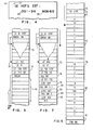
- the display instruction buffer When the display instruction buffer is loaded as shown in Figure 6, it transmits a series of instructions which control the refresh command 11 ( Figure 1 or Figure 2) for a pre-sweep operation.
- the initial instruction in the "LD DI STRT" display instruction buffer simply causes the instruction (in section 70) to be loaded into the instruction sequence which is constant for any display operation, these instructions can be, for example, framing instructions.
- the instruction "LD VRT” causes the loading of the vertical position of the character 72 in the vertical position register 54, as described previously.
- the instruction LD TSB STRT and the following instruction "LD TSB ND” identify the instructions TSB STRT (73) and TSB ND (74) in the buffer instruction sequence ( Figure 5).
- PRCN initiates the pre-scan operation using the apparatus described previously with reference to Figure 2 to scan the sequence of alpha-numeric data and positions in the text buffer 12 ( Figure 5) and to store in overload (OVRWT) the sequence of instructions indicated in the display instruction buffer 13 (FIG. 6) among which are the pre-scan instruction itself as well as any other instructions 75.
- the display instruction buffer 13 is found to have the sequence of instructions illustrated in FIG. 7 to which we will now refer for the repetitive refresh cycle of the 'equipment.
- the pre-sweep instruction itself is overloaded by the instruction 76, Figure 7, namely the "Beam position" (POS BM) instruction.
- the next instruction is the "LD TXT PTR" instruction.
- the pointer 77 ( Figure 5) is fixed so as to indicate the first alpha-numeric character "L” and the characters of the text buffer 12 are sequenced as described previously with reference to Figure 3 by successively sending these characters to the ROS character decoding memory 46 ( Figure 2) while a quiescent pulse is applied to the generator of character segments 47, via line 77, coming from of the sequence logic 60 in order to maintain the display in the idle state, that is to say of no display, during the pre-sweep operation.
- a display start instruction (ST RT DSP) 78 is written in the display instruction buffer to be used during the refresh cycle ( Figure 7) at the point which coincides with the sequencing of characters from the text buffer 12 ( Figure 5).
- ST RT DSP display start instruction
- the coded representation of the characters is sequenced in the character decoding memory 46 in the manner described previously, and the system decodes these characters to finally give an output transmitted on the bus 23 to the segment generator. character 47.
- the generator 47 and, consequently, the electronic display circuits CRT 49 are in the rest state following the signal present on the line 77, no alpha-numeric character n 'is displayed during this pre-sweep cycle.
- the character code 79 from the text buffer ( Figure 5) "(CR)" indicates a carriage return.
- the system calculates the position of the carriage return which is the position of the character "0" 80 in the display of Figure 4
- This carriage return sequence involves access to the line spacing data present in the notepad memory 40 and the transmission of data via the ALU unit 39 where they are added to the last vertical position of carriage from the position register 54 which is then updated to give the new vertical position.
- the left margin position is removed from the notepad memory 44 and sent to the ALU unit 39 where it is combined with the number of withdrawals also stored in the memory 44 in order to to calculate the position of final withdrawal of the character "0" 80 ( Figure 4).
- This updated horizontal carriage return value is loaded into the horizontal position register 51.
- the instruction 81 POS BM XY
- This instruction in fact, tells the cathode ray tube bundle to pass to a defined position which is determined by the updated vertical and horizontal positions then loaded into registers 54 and 51.
- the characters "OUT-96" are sequenced in the character decoding unit 46 in the manner previously described while the quiescence signal is always maintained on line 77; after which, the character code "(TAB)" is decoded in the unit 46 ( Figure 2).
- This operation triggers the tabulation operation described previously with reference to Figure 2 in which, using the tab rack 64 and the selection means 65, the next tab position is calculated and its value is stored in the position register horizontal 51.
- the instruction 84 is stored in the display instruction buffer 13 (FIG. 7) to be used then during the refresh cycle.
- the electronic display circuits bring the beam CRT to the horizontal position which is contained in the horizontal position register 51 after the tabulation calculation has been carried out. This position is, of course, the horizontal position of the alpha-numeric character N 83 ( Figure 4).
- instruction 85 "STRT DSP" is written to the display instruction memory for use in the refresh cycle ( Figure 7).
- the instruction "POS BM" 76 causes the beam CRT to be placed at the position corresponding to the first character "L" 72.
- the text pointer 77 ( Figure 5) is loaded by the buffer memory display instructions so that it indicates a stored representation of the character "L”.
- the display instruction buffer sends the "STRT DSP" instruction 78 which causes a segment signal to replace the quiesce signal on bus 77 69 and is sent to the display electronics.
- CRT and the character segment generator ( Figure 2) which results in sequencing the series of characters from the text storage buffer 12, in unit 46.
- the ROS character decoding unit 46 sends to the character code generator 47 and to the electronic display circuits CRT 49, through the buffer memory 23, the signals necessary to actuate the electronic display circuits so that they trace the alpha-numeric character to be displayed on the CRT tube according to a series of segments. This results in displaying the first line on the CRT cathode ray tube in Figure 4.
- the unit 46 detects the carriage return code (CR) 79 from the text buffer 12, which has as a result that a special non-graphical code signal on the special function bus 57 is applied to the sequence control logic 60, and that this unit 46 sends at the same time on the bus 63 a 7-bit value which specifies the non-graphic code as being a carriage return code applied to the unit ALU 39.
- These two operations cause the return of an output on the bus 43 in the direction of the microinstruction memory 36, which, in turn, sends an instruction, by the unit ALU 39, to the display instruction buffer memory 13 in order to have access in this memory to the following instruction 81 which consists in placing the beam at the indicated carriage return position which has been previously calculated and recorded.
- the instruction 82 originating from the display instruction buffer 13 begins the display at the carriage return position 80 (FIG. 4) and the character sequence "YES- 96 "coming from the text storage buffer 12 passes into the unit 46 as previously described to finally cause the display of the corresponding alpha-numeric characters, as shown in Figure 4.
- the tab code “Tab” 82 from the text buffer 12 is sent to the ROS character decoding unit 46. Again, a signal representing a special function is sent on the special function bus 59 in the direction of the sequence control logic 60 while, at the same time, the character decoding unit 46 transmits a signal indicating the tabulation function. to the ALU unit 39, via the bus 63. It follows that the ALU unit 39 addresses, in the memory of microinstructions 36, an instruction which, in turn, again through the unit ALU 39, indicates in the buffer memory 13 the instruction 34 which brings the beam to the tabulation position previously calculated which corresponds to the position 83 in the display represented in FIG. 4. At this stage, the coded representations of the characters "NO -60 "are sequenced in the ROS unit 46 after the instruction of" STRT DSP "85 ( Figure 7) and the rest of the second line” NON-60 "is displayed on the CRT tube of Figure 4.
Landscapes
- Engineering & Computer Science (AREA)
- Theoretical Computer Science (AREA)
- Physics & Mathematics (AREA)
- General Physics & Mathematics (AREA)
- Remote Sensing (AREA)
- Computer Hardware Design (AREA)
- Radar, Positioning & Navigation (AREA)
- Health & Medical Sciences (AREA)
- Artificial Intelligence (AREA)
- Audiology, Speech & Language Pathology (AREA)
- Computational Linguistics (AREA)
- General Health & Medical Sciences (AREA)
- General Engineering & Computer Science (AREA)
- Controls And Circuits For Display Device (AREA)
Abstract
Système de traitement de texte à affichage sur un tube cathodique (15) comprenant un moyen d'entrée de données (16) tel qu'un clavier, un processeur (10), une mémoire tampon de texte (12), une mémoire tampon d'instructions d'affichage (13), une logique de commande de rafraîchissement (11) et des circuits de génération et d'affichage de caractère (14). Lorsqu'un code de tabulation ou un code de retour de chariot est détecté, l'unité arithmétique du processeur (10) calcule la position de tabulation ou de retour de chariot du caractère suivant pendant le cycle de formation des caractères, cette position étant ensuite emmagasinée en mémoire de sorte que le système y a accès, pendant le cycle de rafraîchissement, en réponse au code de tabulation ou de retour de chariot correspondant.Word processing system for displaying on a cathode ray tube (15) comprising data input means (16) such as a keyboard, a processor (10), a text buffer memory (12), a data buffer display instructions (13), refresh control logic (11) and character generation and display circuits (14). When a tabulation or carriage return code is detected, the arithmetic unit of the processor (10) calculates the tabulation or carriage return position of the next character during the character formation cycle, this position then being stored in memory so that the system can access it, during the refresh cycle, in response to the corresponding tab or carriage return code.
Description
La présente invention concerne les systèmes de traitement et d'affichage de texte et, plus particulièrement, un système de traitement de texte à affichage sur tube cathodique (CRT) dans lequel un bloc de données alpha-numériques pouvant être par exemple toute une page à afficher doit être maintenu sur le tube d'affichage CRT.The present invention relates to text processing and display systems and, more particularly, to a cathode ray tube display (CRT) word processing system in which an alpha-numeric data block which can be for example an entire page with display must be maintained on the CRT display tube.
La préparation d'un document d'affaires implique souvent la frappe et l'édition de plusieurs ébauches du document avant que ce dernier ne soit complet, correct et présenté sous une forme qui soit facilement compréhensible et esthétique à l'oeil. Les étapes de préparation d'un document imprimé sous sa forme finale exigent souvent: (1) la frappe d'une ébauche à partir de données grossières, d'une dictée ou de notes; (2) des ratures, des insertions des restructurations et des corrections par un éditeur; (3) la refrappe en utilisant l'ébauche éditée comme source d'information; (4) la réédition pour s'assurer des corrections et obtenir la perfection esthétique; (5) la refrappe telle qu'elle est exigée par l'étape (4) et la réédition pour obtenir une copie finale correcte.The preparation of a business document often involves typing and editing several drafts of the document before it is complete, correct and presented in a form that is easily understandable and aesthetic to the eye. The stages of preparing a printed document in its final form often require: (1) typing a draft from rough data, dictation or notes; (2) erasures, insertions of restructurings and corrections by an editor; (3) recaps using the edited draft as a source of information; (4) re-editing to ensure corrections and obtain aesthetic perfection; (5) re-types as required by step (4) and re-edition to obtain a correct final copy.
D'après ce qui précède, chaque fois qu'il y a frappe d'information, cette information doit être relue et éventuellement éditée pour s'assurer qu'elle est correcte et , chaque fois qu'elle est éditée, elle doit être refrappée. Ce procédé est extrêmement long, car il y a perte de temps au niveau de la secrétaire, puisqu'il y a refrappe et au niveau de l'éditeur, puisqu'il y a réédition.According to the above, whenever information is typed, this information must be re-read and possibly edited to ensure that it is correct and, each time it is edited, it must be re-typed. . This process is extremely long, because there is a loss of time at the level of the secretary, since there is rewrite and at the level of the editor, since there is re-edition.
L'art antérieur propose plusieurs dispositifs pour diminuer la perte de temps due à la refrappe et la réédition des documents d'affaires. Un approche traditionnelle de l'art antérieur consiste à enregistrer les caractères frappés sur un second support, par exemple un support magnétique, qui est sélectivement utilisé par la dactylographe pour commander la machine à écrire afir que cette dernière imprime automatiquement en sortie l'information contenue dans la première ébauche avec les changements apportés à l'édition. Depuis quelques années, cette approche traditionnelle est remplacée par des systèmes de traitement de texte qui utilisent un affichage par tube cathodique (CRT), ou des dispositifs semblables, qui affichent l'information introduite par exemple par clavier dans le terminal d'entrée d'un système de traitement de texte. L'information entrée est affichée et l'opérateur peut apporter des corrections aux données ainsi affichées. Ces corrections entraînent, bien entendu, l'entrée de nouvelle données, la suppression de données existantes ou l'insertion de nouvelles données.The prior art proposes several devices to reduce the loss of time due to the re-typing and re-edition of business documents. A traditional approach of the prior art consists in recording the characters struck on a second support, for example a magnetic support, which is selectively used by the typist to control the typewriter so that the latter automatically prints the information contained as output. in the first draft with changes to the edition. For a few years, this traditional approach has been replaced by word processing systems which use a cathode ray tube display (CRT), or similar devices, which display the information entered for example by keyboard in the input terminal of a word processor. The information entered is displayed and the operator can make corrections to the data thus displayed. These corrections entail, of course, the entry of new data, the deletion of existing data or the insertion of new data.
Actuellement, les systèmes de traitement de texte autonomes contiennent les éléments électroniques nécessaires pour effectuer l'édition avec affichage cathodique des données introduites au clavier. Ces systèmes d'édition de texte ont, en général, leur propre mémoire de grande capacité dans laquelle les caractères à afficher sont emmagasinés sous une forme quelconque appropriée. Lorsque l'information affichée est supposée être correcte, les données de la mémoire de grande capacité sont transmises à un microprocesseur central qui alors commande l'impression des données en sortie sur une imprimante classique quelconque.Currently, stand-alone word processing systems contain the electronic components necessary for editing with cathodic display of data entered on the keyboard. These text editing systems generally have their own large capacity memory in which the characters to be displayed are stored in any suitable form. When the information displayed is assumed to be correct, the data in the large-capacity memory is transmitted to a central microprocessor which then controls the printing of the output data on any conventional printer.
Dans les systèmes de traitement de texte décrits ci-dessus, de nombreuses opérations telles que la tabulation et le retour de chariot impliquent traditionnellement un nombre considérable de calculs chaque fois qu'apparaît un code de tabulation ou de retour de chariot au cours du fonctionnement du système. Par exemple, lorsqu'on rencontre un code de tabulation, le système doit procéder à des calculs élaborés pour déterminer la position de tabulation et ensuite passer à la position où doit reprendre l'impression. Ce calcul implique le balayage d'un moyen d'emmagasinage des positions de tabulation, par exemple, une crémaillère de tabulation, ainsi que des moyens pour faire la corrélation entre cette information et les diverses données relatives aux marges.In the word processing systems described above, many operations such as tabulation and carriage return traditionally involve a considerable number of calculations each time a tabulation or carriage return code occurs during operation of the system. For example, when a tabulation code is encountered, the system must perform calculations developed to determine the tab position and then move to the position where printing should resume. This calculation involves the scanning of a means of storing the tabulation positions, for example, a tabulation rack, as well as means for correlating this information with the various data relating to the margins.
Dans l'approche décrite ci-dessus où des caractères sont emmagasinés sur un support secondaire, par exemple sur un support magnétique, durant l'édition, la sortie de la copie éditée, que ce soit sous forme d'ébauche ou de copie finale, sur une imprimante ou une machine à écrire, ne présente aucun problème étant donné que le calcul des données de tabulation et des données de retour de chariot est conforme aux vitesses de fonctionnement de l'équipement qui sont de l'ordre de 20 à 60 caractères par seconde.In the approach described above where characters are stored on a secondary medium, for example on a magnetic medium, during editing, the output of the edited copy, whether in the form of a draft or a final copy, on a printer or typewriter, presents no problem since the calculation of the tabulation data and the carriage return data is in accordance with the operating speeds of the equipment which are of the order of 20 to 60 characters per second.
Il est à noter que les approches complexes mentionnées ci-dessus mises en jeu dans le calcul des codes de tabulation et de retour de chariot répondent à un besoin de simplifier et de faciliter le plus possible le travail entre l'opératrice et sa machine. C'est ainsi que, dans les systèmes de traitement de texte, les opérations d'entrée par l'opératrice, telles que le opérations de tabulation ou de retour de chariot, sont aussi proches que possibles de celles utilisées depuis près d'un siècle dans les machines à écrire classiques. Ainsi, lorsque sont calculées des fonctions de tabulation ou de retour de chariot, l'opératrice du système de traitement de texte n'a pas grand chose à rajouter aux fonctions de tabulation et de retour de chariot entrées au clavier d'une simple machine à écrire par l'opératrice.It should be noted that the complex approaches mentioned above used in the calculation of the tabulation and carriage return codes meet a need to simplify and facilitate as much as possible the work between the operator and her machine. Thus, in word processing systems, operator input operations, such as tabbing or carriage return, are as close as possible to those used for almost a century in conventional typewriters. Thus, when tabulation or carriage return functions are calculated, the operator of the word processing system has little to add to the tabulation and carriage return functions entered on the keyboard of a simple machine. write by the operator.
Or, maintenant que des dispositifs d'affichage viennent s'ajouter aux systèmes de traitement de texte, il apparaît vivement avantageux pour l'opératrice de maintenir les entrées de tabulation et de retour de chariot aussi simples et aussi proches que possible des entrées effectuées sur une machine à écrire classique.However, now that display devices are added to the word processing systems, it appears highly advantageous for the operator to keep the tabulation and carriage return entries as simple and as close as possible to the entries made on a classic typewriter.
Cependant, dans un système de traitement de texte où les entrées de tabulation et de retour de chariot par l'opératrice sont des entrées classiques, les désignations des codes de tabulation et de retour de chariot sont incluses dans la chaîne de données de caractères emmagasinée. Il s'ensuit que le système doit procéder à des calculs relativement longs pour convertir ces codes de tabulation et de retour de chariot en des données de position affichées sur l'écran cathodique.However, in a word processing system where the tabulation and carriage return entries by the operator are conventional entries, the designations of the tabulation and carriage return codes are included in the stored character data string. It follows that the system must perform relatively long calculations to convert these tabulation and carriage return codes into position data displayed on the cathode-ray screen.
Malheureusement, dans les systèmes de traitement et d'affichage de texte, le facteur temps joue un rôle critique. Il s'est avéré très difficile, même dans les petits affichages de l'ordre de une à cinq lignes, d'effectuer toutes les opérations de traitement de données nécessaires pour former l'affichage alpha-numérique durant chaque cycle de rafraîchissement. Dans les affichages à tube cathodique afin d'éviter tout clignotement, la cadence de rafraîchissement doit être de l'ordre de 45 hertz. Cela accorde à chaque cycle de rafraîchissement une durée d'environ 22 millisecondes. Avec le développement des systèmes de traitement et d'affichage de texte, le problème s'est aggravé étant donné que ces systèmes exigent des affichages de pages entières qui, bien entendu, font appel à un nombre accru des opérations à effectuer durant le cycle de rafraîchissement de 22 millisecondes. Dans les systèmes de traitement de données, le problème s'est encore aggravé par le besoin d'avoir des affichages cathodiques à espacement proportionnel, compatibles avec les systèmes dans lequels l'impression est à. espacement proportionnel c'est-à-dire, dans lesquels les caractères alpha-numériques ont une largeur variable. Dans- ces systèmes à espacement proportionnel au lieu d'avoir environ cent positions de caractères possibles par ligne d'affichage, il y a plus de sept cent cinquante positions d'échappement possibles qui doivent être prises en compte lors des calculs de position des caractères affichés. Il s'ensuit que les opérations de traitement de données nécessaires pour assurer chaque cycle de rafraîchissement, sont encore plus complexes et longues.Unfortunately, in word processing and display systems, the time factor plays a critical role. It has proved very difficult, even in small displays of the order of one to five lines, to carry out all the data processing operations necessary to form the alpha-numeric display during each refresh cycle. In cathode ray tube displays to avoid flashing, the refresh rate should be around 45 hertz. This allows each refresh cycle to last approximately 22 milliseconds. With the development of text processing and display systems, the problem has worsened since these systems require display of entire pages which, of course, require an increased number of operations to be performed during the work cycle. 22 millisecond refresh. In data processing systems, the problem has been further compounded by the need for proportional spacing cathode displays, compatible with systems in which printing is at. proportional spacing, that is, in which the alpha-numeric characters have a variable width. In these proportional spacing systems, instead of having about one hundred possible character positions per display line, there are more than seven hundred and fifty possible escape positions which must be taken into account when calculating character positions. displayed. It follows that the operations of data processing required to ensure each refresh cycle, are even more complex and time consuming.
Une approche utilisée pour réduire au minimum le temps de traitement des données durant les cycles de rafraîchissement consiste à structurer (mettre au format) une mémoire matricielle de sorte qu'elle ait toutes les positions de caractères possibles de l'affichage CRT et à emmagasiner à chaque position de caractère suffisamment de données pour identifier à cette position le caractère ou l'absence de caractère ainsi que son attribut associé. Tandis que cette approche offre une solution acceptable au temps de rafraîchissement nécessaire et au système employant des affichages relativement petits de l'ordre de 1 à 5 lignes, elle s'avère encombrante et dispendieuse dans les systèmes de traitement et d'affichage de texte traitant des pages entières. Le système exige environ un multiplet de données à chaque position d'emmagasinage soit environ 100 x 70 c'est-à-dire 7000 multiplets de données à chaque page entière affichée.One approach used to minimize data processing time during refresh cycles is to structure (format) a matrix memory so that it has all of the possible character positions from the CRT display and to store at each character position sufficient data to identify at this position the character or the absence of a character as well as its associated attribute. While this approach offers an acceptable solution to the refresh time required and to the system employing relatively small displays of the order of 1 to 5 lines, it is cumbersome and expensive in processing and displaying text processing systems. whole pages. The system requires approximately one byte of data at each storage position, or approximately 100 x 70, that is, 7000 bytes of data on each entire page displayed.
L'objet de la présente invention est donc un système de traitement de texte à affichage de données alpha-numériques sous forme de pages entières ayant un fréquence de rafraîchissement qui évite tout clignotement de l'affichage tout en utilisant une capacité d'emmagasinage réduite à un minimum.The object of the present invention is therefore a word processing system with display of alpha-numeric data in the form of whole pages having a refresh rate which prevents the display from blinking while using a storage capacity reduced to a minimum.
Cet objet est satisfait en utilisant un système d'affichage à tube cathodique comportant des moyens de déflexion de position pour déplacer le faisceau du tube cathodique sur une suite de positions sélectionnées en référence à un premier et à un second axes de coordonnées en réponse à des signaux de position, des moyens de position pour engendrer ces signaux de position, des moyens de définition de caractère sensibles aux signaux représentant un caractère sélectionné pour commander la déflexion du faisceau selon une configuration représentant un caractère sélectionné et pour moduler l'intensité du faisceau sur cette configuration afin de définir le caractère, et des moyens pour engendrer les signaux représentant un caractère sélectionné et pour les appliquer aux moyens de définition de caractère.This object is satisfied by using a cathode-ray tube display system comprising position deflection means for moving the beam of the cathode-ray tube to a series of positions selected with reference to a first and a second coordinate axes in response to position signals, position means for generating these position signals, character definition means sensitive to the signals representing a character selected to control the deflection of the beam according to a configuration representing a selected character and for modulating the intensity of the beam on this configuration in order to define the character, and means for generating the signals representing a selected character and for applying them to the character definition means.
Le système comprend des moyens d'emmagasinage pour emmagasiner séquentiellement les représentations codées des caractères sélectionnés à afficher et des codes de tabulation et de retour de chariot des caractères affichés.The system includes storage means for sequentially storing the coded representations of the selected characters to be displayed and the tab and carriage return codes of the displayed characters.
Les moyens de position pour engendrer les signaux de position comprennent: des moyens de calcul qui, en réponse à un code de tabulation auquel on a accès, calculent la position de tabulation du caractère suivant à afficher par rapport au premier axe de coordonnée uniquement durant le cycle initial au cours duquel est formé chacun des caractères sélectionnés, une mémoire pour emmmagasiner chaque position de tabulation calculée, et des moyens d'accès fonctionnant uniquement durant des cycles de rafraîchissement pour avoir accès à la position de tabulation préalablement calculée, et emmagasinée dans ladite mémoire, en réponse au code de tabulation correspondant.The position means for generating the position signals comprise: calculation means which, in response to a tabulation code to which one has access, calculate the tabulation position of the next character to be displayed relative to the first coordinate axis only during the initial cycle during which each of the selected characters is formed, a memory for storing each calculated tab position, and access means operating only during refresh cycles to have access to the previously calculated tab position, and stored in said memory, in response to the corresponding tabulation code.
Brève description des figures
- La Figure 1 représente schématiquement un diagramme de fonctionnement général du système de la présente invention.
- La Figure 2 représente un schéma plus détaillé de la logique représentée sur la Figure 1.
- La Figure 3 représente un schéma montrant les impulsions d'horloge Pl, P2 et P3 utilisées pour mesurer le temps des diverses opérations intervenant dans le fonctionnement de la logique de la Figure 2.
- La Figure 4 représente un affichage alpha-numérique donné comme exemple pour illustrer le fonctionnement du système.
- La Figure 5 représente un schéma de la séquence des instructions emmagasinées dans la mémoire tampon de texte, nécessaires pour produire l'affichage alpha-numérique représenté sur la Figure 4.
- La Figure 6 représente schématiquement la séquence des instructions emmagasinées dans la mémoire tampon d'instructions d'affichage nécessaires à l'opération de balayage préalable des données alpha-numériques de l'affichage de la Figure 4.
- La Figure 7 représente schématiquement la séquence des instructions emmagasinées dans la mémoire tampon d'instructions d'affichage durant le rafraîchissement afin de maintenir l'affichage alpha-numérique représenté sur la Figure 4.
- Figure 1 schematically shows a general operating diagram of the system of the present invention.
- Figure 2 shows a more detailed diagram of the logic shown in Figure 1.
- FIG. 3 represents a diagram showing the clock pulses P1, P2 and P3 used to measure the time of the various operations involved in the operation of the logic of FIG. 2.
- Figure 4 shows an alpha-numeric display given as an example to illustrate the operation of the system.
- Figure 5 shows a diagram of the sequence of instructions stored in the text buffer necessary to produce the alpha-numeric display shown in Figure 4.
- FIG. 6 schematically represents the sequence of instructions stored in the display instruction buffer necessary for the operation of previously scanning the alpha-numeric data of the display in FIG. 4.
- Figure 7 schematically shows the sequence of instructions stored in the display instruction buffer during refresh to maintain the alpha-numeric display shown in Figure 4.
Dans la description du mode de réalisation de la présente invention, on va tout d'abord décrire le système de l'invention, description qui sera suivie des opérations impliquées dans le système. Le système représenté de façon très schématique sur la Figure 1 peut être divisé en cinq composants principaux, à savoir, le processeur principal 10, la logique de commande de rafraîchissement 11, les unités de mémoire servant de mémoire tampon, c'est-à-dire, la mémoire tampon de texte 12 qui emmagasine le texte à afficher et la mémoire tampon d'instructions d'affichage 13 qui emmagasine diverses intructions d'affichage associées au texte à afficher et les circuits de génération et d'affichage de caractères 14 qui commandent directement le balayage du tube cathodique CRT 15.In the description of the embodiment of the present invention, we will first describe the system of the invention, a description which will be followed by the operations involved in the system. The system shown very diagrammatically in FIG. 1 can be divided into five main components, namely, the
Le processeur principal 10 peut être un microprocesseur classique disponible.dans le commerce, dont le rôle consiste à recevoir les données d'entrée provenant généralement de la frappe au clavier par l'opératrice et à emmagasiner ces données dans la mémoire tampon de texte 12. On suppose que lorsque l'information alpha-numérique est affichée sur le tube cathodique CRT 15, l'opératrice entre, par l'intermédiaire du clavier 16, de nouveaux caractères. Pour emmagasiner ces caractères dans la mémoire tampon de texte 12, il faut tout d'abord arrêter la commande de rafraîchissement du tube cathodique. Cette opération se fait à l'aide du processeur principal qui engendre et maintient un signal sur la ligne d'arrêt de demande 17 et qui attend une réponse provenant de la logique de commande de rafraîchissement 11 sur la ligne d'arrêt 18. Lorsque ce cas se présente, le microprocesseur principal 10 remet à jour la mémoire tampon de texte 12, par l'entremise du bus 19, afin d'emmagasiner les nouveaux caractères à leur position appropriée; en outre, le processeur 10 initialise la mémoire tampon d'instructions d'affichage 13, par l'entremise du bus 20. Le microprocesseur principal 10 libère les circuits électroniques de rafraîchissement de leur état d'arrêt en supprimant la sortie provenant de la ligne d'arrêt de demande 17. A ce stade, l'appareil sous la commande de la mémoire tampon d'instructions d'affichage procède à un balayage initial des données emmagasinées à afficher, balayage qui peut être dénommé prébalayage, au cours duquel sont effectués et emmagasinés tous les calculs de tabulation et/ou de retour de chariot.The
Dans le système général représenté sur la Figure 1, la mémoire tampon de texte contient les représentations codées des caractères alpha-numériques à afficher tandis que la mémoire tampon d'instructions d'affichage 13 contient la séquence des instructions qui vont commander la mise en séquence des caractères alpha-numériques du texte provenant de la mémoire tampon de texte 13, ainsi que les attributs des caractères alpha-numériques et leur position sur le tube d'affichage CRT. La logique de commande de rafraîchissement 11 remplit les fonctions associées à la recherche et à l'exécution des instructions provenant de la mémoire tampon d'instructions d'affichage 13. Ces instructions qui seront décrites de façon plus détaillée dans la suite en référence aux autres figures sont les suivantes:
- des instructions de chargement d'un parmi plusieurs registres pour préciser, par exemple, une nouvelle position horizontale ou verticale sur le tube cathodique, ou l'adresse de l'instruction suivante ou du caractère suivant,
- après toute modification des données du texte dans la mémoire tampon de texte, des instructions de re-balayage de la mémoire tampon de texte et de ré-écriture de la mémoire tampon d'instructions d'affichage afin qu'elle reflète l'état de la mémoire tampon de texte,
- des instructions conduisant à l'affichage des caractères présents dans la mémoire tampon de texte 12 qui sont indiqués par les moyens d'adressage de la mémoire tampon de texte,
- des instructions de mise en service ou au repos des divers modes d'affichage des caractères (attributs de caractère) qu'il s'agisse d'un caractère souligné, éclairé plus fortement ou clignotant,
- durant chaque cycle de rafraîchissement, après que tous les caractères ont été rafraîchis et qu'il reste encore un temps disponible avant le début du cycle de rafraîchissement suivant, des instructions qui permettent au tube cathodique d'assumer un état de repos durant cette période de temps, c'est-à-dire, un état durant lequel sera dissipé un minimum d'énergie.
- instructions for loading one of several registers to specify, for example, a new horizontal or vertical position on the cathode ray tube, or the address of the next instruction or of the next character,
- after any changes to the text data in the text buffer, instructions to re-scan the text buffer and rewrite the display instruction buffer to reflect the status of the text buffer,
- instructions leading to the display of the characters present in the
text buffer memory 12 which are indicated by the addressing means of the text buffer memory, - instructions for putting into service or for resting the various display modes of the characters (character attributes) whether it is an underlined character, more strongly lit or flashing,
- during each refresh cycle, after all the characters have been refreshed and there is still time available before the start of the next refresh cycle, instructions which allow the cathode ray tube to assume a quiescent state during this period of time, that is to say, a state during which a minimum of energy will be dissipated.
Pour mener à bien ces diverses activités, la mémoire tampon d'instructions d'affichage communique avec la logique de commande de rafraichissement 11, le long du bus 21, et la logique de commande de rafraîchissement 11 communique avec les circuits de génération et d'affichage de caractères 14, par les connexions suivantes. Lorsque des caractères sont mis en jeu durant un cycle de rafraîchissement, la logique de commande de rafraîchissement 11 active la ligne de segment de caractère 21, ce qui permet aux circuits de génération et d'affichage de caractères de former, suivant des segments de caractère affichés sur le tube cathodique, une séquence de caractères dont les représentations codées sont successivement envoyées depuis la mémoire tampon de texte, par le bus 22, à la logique de commande de rafraîchissement d'où elles sont envoyées aux circuits électroniques 14, par le bus 23. La nature des circuits électroniques de génération et d'affichage de caractères ne fait pas partie de la présente invention, et, de ce fait, ne sera pas décrite plus avant. Des circuits électroniques classiques de génération et d'affichage de segments de caractère pour tube cathodique peuvent être utilisés et peuvent être du type décrit dans le brevet des E.U.A. 3 609 745.To carry out these various activities, the display instruction buffer communicates with the
Il y a deux sorties provenant des circuits de génération et d'affichage de caractères, à savoir, un signal sur la ligne 24 qui indique que le caractère qui a été dernièrement requis pour être rafraîchi par la logique de commande de rafraîchissement 11 est complet, et un signal sur la ligne 25 qui indique que le temps réservé à la période de rafraîchissement minimale est totalement écoulé et que la période de rafraîchissement suivante devrait commencer. Comme cela a été mentionné préalablement, si, durant un cycle de rafraîchissement donné, tous les caractères sont formés avant que n'apparaisse ce signal de fin de période de rafraîchissement, la logique de commande de rafraîchissement 11 applique sur la ligne 27 un signal de repos qui met alors au repos les circuits électroniques 14.There are two outputs from the character generation and display circuits, namely, a signal on
En outre, les données relatives à la position des caractères alpha-numériques affichés sont envoyées à partir de la logique de commande de rafraîchissement, le long du bus 28, et les divers attributs de caractère décrits ci-dessus sont envoyés à partir de la logique de commande de rafraîchissement 11 le long du bus 29.In addition, the positional data of the displayed alpha-numeric characters are sent from the refresh control logic along the
La Figure 2 représente de façon plus détaillée le système représenté sous forme très générale sur la Figure 1. Sur la Figure 2, les unités fonctionnelles sont représentées avec leur logique et sont délimitées par une ligne discontinue; ces unités logiques, qui ont la même référence que celles utilisées sur la Figure 1, sont le processeur principal 10, la logique de commande de rafraîchissement 11, la mémoire tampon de texte 12, la mémoire tampon d'instructions d'affichage 13, les circuits électronique de génération et d'affichage de caractères 14 et le tube cathodique CRT 15.Figure 2 shows the system in more detail shown in very general form in Figure 1. In Figure 2, the functional units are represented with their logic and are delimited by a broken line; these logic units, which have the same reference as those used in FIG. 1, are the
Le processeur principal 10 et la logique de commande de rafraîchissement 11 se partagent les deux mémoires fondamentales du système, à savoir, la mémoire tampon de texte 12 et la mémoire tampon d'instructions d'affichage 13 si bien que le processeur 10 ou la logique 11 peuvent avoir indépendamment accès à chacune d'elles. Comme cela sera décrit de façon plus détaillée dans la suite, le processeur principal ainsi que la logique de commande de rafraîchissement peuvent modifier le contexte de la mémoire tampon d'instructions d'affichage 13. Cependant, seul le processeur principal peut modifier le contenu de la mémoire tampon de texte.The
La mémoire tampon d'instructions d'affichage 13 comprend une mémoire d'instructions 30 qui a une largeur de seize bits (ou éléments d'information binaires) dont l'accès se fait par une adresse à seize bits, par le compteur d'adresse 31 et le registre de maintien de polarité à seize bits 32 lequel verrouille l'adresse jusqu'à ce que l'application de l'impulsion d'horloge P3 permette l'envoi de l'adresse du registre 32 à la mémoire d'instructions 30 de manière à indiquer l'instruction suivante. Le texte alpha-numérique est emmagasiné dans la mémoire de texte 33 de la mémoire tampon de texte 12 sous forme de représentations de caractères alpha-numériques codées ayant chacune une largeur de un multiplet, mémoire dont l'accès se fait par une adresse provenant du compteur d'adresse seize bits 34 par le registre de maintien de polarité 35 lequel exige également une impulsion d'horloge P3 pour indiquer la représentation au caractere suivant aans la mémoire 33.The
A ce stade du fonctionnement, on va passer à la description de l'horloge représentée sur la Figure 3. Le système de la présente invention est commandé par une horloge à trois phases qui engendrent trois impulsions qui ne se chevauchent pas, P1, P2 et P3. L'impulsion Pl est utilisée pour incrémenter le compteur de microprogramme du système qui va être décrit dans la suite de façon plus détaillée ainsi que pour chronométrer les données introduites dans la mémoire tampon d'ALU qui sera également décrite de façon plus détaillée dans la suite. L'impulsion P2 est utilisée pour charger, ou incrémenter, ou décrémenter divers registres. L'impulsion P3 est utilisée pour charger les mémoires tampon à partir des divers registres et compteurs d'adresses.At this stage of operation, we will move on to the description of the clock shown in FIG. 3. The system of the present invention is controlled by a three-phase clock which generates three non-overlapping pulses, P1, P2 and P3. The pulse P1 is used to increment the system firmware counter which will be described in more detail below as well as to time the data entered in the ALU buffer which will also be described in more detail below. . The P2 pulse is used to load, or increment, or decrement various registers. Pulse P3 is used to load the buffer memories from the various registers and address counters.
La logique de commande de rafraîchissement 11, Figure 2, va maintenant être décrite de façon plus détaillée. Comme cela a été mentionné préalablement, la logique de commande de rafraîchissement remplit les fonctions associées à la recherche et à l'exécution des instructions provenant de la mémoire tampon d'instructions d'affichage. Comme cela sera décrit dans la suite en référence au fonctionnement du système de la présente invention, la logique de commande de rafraîchissement fonctionne non seulement durant le cycle de rafraîchissement mais également durant le cycle initial au cours duquel est formé chacun des caractères à afficher. Etant donné que la mémoire tampon d'instructions d'affichage 13 fonctionne durant la formation initiale du caractère d'un façon différente de celle utilisée durant le cycle de rafraîchissement de caractère, les instructions produites sont différentes, et, par voie de conséquence, la logique de commande.de rafraîchissement fonctionne différemment. Dans tous les cas, la logique de commande de rafraîchissement 11, Figure 2, a emmagasinée dans une mémoire permanente 36, une grande variété de groupes de microinstructions agencées de manière à commander l'interaction des divers composants du système représenté sur la Figure 2 de manière à réaliser les instructions obtenues à partir de la mémoire tampon d'instructions d'affichage 13 dans une séquence déterminée par la commande de séquence 60. Dans le mode de réalisation de la présente invention, la mémoire 36 est une mémoire permanente ROS de 256 mots de quarante bits chacun à laquelle sont associés des moyens d'adressage comprenant un compteur à 8 bits, 37 et un registre de maintien de polarité à 8 bits, 38. Le compteur d'adresses et le registre de maintien de polarité fonctionnent de la même façon que celle utilisée par les moyens décrits pour adresser la mémoire d'instructions 30 ou la mémoire de texte 33, c'est-à-dire, que l'application de l'impulsion d'horloge P3 au registre 38 fait que l'adresse appliquée au registre 38 et qui s'y trouve maintenue, indique le multiplet de microinstruction approprié dans la mémoire ROS 36. Tous les calculs de la logique de commande de rafraîchissement sont effectués dans l'unité logique et arithmétique (ALU 39) qui reçoit les données par les bus d'entrée ALU 40 et 41. La sortie de l'unité ALU 39 est verrouillée dans le registre de maintien de polarité à 16 bits 42 par l'application de l'impulsion d'horloge Pl qui fait que les données présentes dans le registre 42 sont envoyées sur le bus de sortie ALU 43.The
Le système comprend en outre une mémoire bloc-notes 44 dans laquelle peuvent être emmagasinés de nombreux paramètres temporaires relatifs au texte affiché. Par exemple, dans une mémoire de 8 mots à 16 bits chacun, peuvent être emmagasinés les paramètres tels que: espacement entre les lignes, marge gauche, sous-marge. Tous ces paramètres sont nécessaires pour calculer un retour de chariot, comme cela sera décrit dans la suite.The system further includes a notepad memory 44 in which numerous temporary parameters relating to the displayed text can be stored. For example, in a memory of 8 words at 16 bits each, parameters such as: line spacing, left margin, sub-margin can be stored. All these parameters are necessary to calculate a carriage return, as will be described below.
Une unité de décodage de caractères 46 fonctionne pour décoder ou traduire la représentation codée des caractères alpha-numériques emmagasinés dans la mémoire tampon de texte en une sortie transmise par le bus 23 au générateur de segments de caractère 47 qui, à son tour, engendre et transmet par le bus 48 aux circuits d'affichage 49 du tube CRT, les signaux nécessaires pour activer ces circuits de façon à ce qu'ils tracent le caractère alpha-numérique à afficher sur le tube CRT sous forme d'une série de segments. L'entrée de la représentation codée du caractère à afficher à partir de la mémoire de texte 33 sur l'unité de décodage de caractères 46 passe par le bus d'entrée 41 pour atteindre l'unité ALU 39 à partir de laquelle elle est envoyée au bus de sortie 43 d'où elle est chargée dans le registre de maintien de polarité de code de caractère 50 à partir duquel elle est envoyée dans l'unité de décodage de caractère 46 par une impulsion d'horloge d'entrée P2.A character decoding unit 46 operates to decode or translate the coded representation of the alpha-numeric characters stored in the text buffer into an output transmitted by the
Un registre de positions horizontales à 10 bits 51 garde trace de la position d'échappement. Lorsqu'une opération d'affichage est amorcée, la position horizontale initiale est emmagasinée dans la mémoire d'instructions d'affichage 30. Le chargement de cette position horizontale initiale dans le registre 51 se fait en transmettant la position sur le bus 41 qui passe dans l'unité ALU 39 et dans le registre de sortie 42 pour passer ensuite sur le bus de sortie 43 à partir duquel elle est chargée dans le registre de position horizontale 51. Durant un cycle de rafraîchissement au cours duquel sont affichés les caractères, la position horizontale du caractère est communiquée au générateur de caractères 47, par le bus 28'. Ensuite, une fois que le caractère représenté par le code chargé dans l'unité de décodage de caractères 46 a été affiché ou rafraîchi, l'échappement horizontal est à incrémenter en chargeant la valeur d'échappement du caractère affiché sur le bus 40, par le bus 52, et en ajoutant cette valeur d'échappement à la valeur d'échappement horizontal qui a été appliqué dans l'unité ALU 39, par les bus 53 et 41. Cette valeur remise à jour repasse ensuite à partir de l'unité ALU et de son registre de sortie 42, par le bus 43, dans le registre 51.A 10-bit horizontal position register 51 keeps track of the escape position. When a display operation is initiated, the initial horizontal position is stored in the
Le registre de positions verticales 54 garde trace de la position verticale de l'affichage d'une façon semblable. La position verticale initiale est chargée dans le registre 54 d'une façon semblable à celle utilisée pour charger le registre de positions horizontales 51, c'est-à-dire, la position verticale initiale est transmise depuis la mémoire 30, par l'intermédiaire de l'unité ALU 39 et du registre de sortie 42, au registre de positions verticales 54. Durant un cycle de rafraîchissement des caractères affichés, la position verticale du caractère est communiquée au générateur de caractères 47, par le bus 28''. Ensuite, si à un caractère donné est associé un déplacement vertical, l'unité 46 charge cet incrément vertical par le bus 41 et le bus 55, dans l'unité ALU 39 d'où il est ajouté à la dernière position verticale, ou position en cours provenant du générateur 54 et passant par le bus 56 et le bus 40 pour atteindre l'unité ALU 39 à partir de laquelle la valeur mise à jour est renvoyée par le registre de sortie et le bus 43, au registre de positions verticales 54.The vertical position register 54 keeps track of the vertical position of the display in a similar manner. The initial vertical position is loaded into
Les représentations codées des divers attributs de caractère, tels que le soulignement, la brillance ou le clignotement d'un caractère qui sont emmagasinées dans la mémoire d'instructions d'affichage 30, sont chargées dans le registre d'attributs de caractère 57 au moment où ils doivent être exécutés. Le chargement du registre d'attributs de caractère 57 se fait par l'unité ALU de la manière décrite préalablement. Le registre 57 qui est un registre à 3 bits contenant le code qui détermine les attributs de caractère, envoie ce code par le bus 29 dans le registre de segments de caractère 47 et aux circuits d'affichage 49 du tube cathodique pour actionner ce dernier suivant le mode d'attribut de caractère requis.The coded representations of the various character attributes, such as underlining, brightness, or blinking of a character which are stored in the
Comme cela a été mentionné préalablement, un aspect important de la présente invention implique des moyens sensibles à un code de tabulation auquel on a eu accès pour calculer la position de tabulation du caractère suivant à afficher uniquement durant le cycle initial au cours duquel est formé chacun des caractères sélectionnés. Cette fonction va maintenant être décrite. On suppose que l'on se trouve dans un cycle initial après un changement de l'information à afficher et que les représentations codées des caractères emmagasinés dans la mémoire de texte 33 sont séquentiellement adressées par le compteur d'adresses 34 et le registre 35 (prébalayage) lorsque la représentation codée suivante est un code de tabulation. Comme toute autre représentation codée adressée, le code de tabulation est envoyé sur le bus 41 pour passer dans l'unité ALU 39 et de là, par le bus 43, dans l'unité de décodage de caractères 46 qui, après détection d'un code de tabulation, transmet un signal représentant un code non graphique spécial sur un bus de fonction spéciale 59 en direction de la logique de commande de séquence qui, en combinaison avec le réseau de microinstructions 36, commande l'exécution des instructions dans le système de la présente invention. Il est à noter que ce signal n'est pas différencié des codes de tabulation et autres codes non graphiques, tels que les codes de retour de chariot.As mentioned previously, an important aspect of the present invention involves means sensitive to a tabulation code to which we had access to calculate the tabulation position of the next character to be displayed only during the initial cycle during which each is formed. selected characters. This function will now be described. We assume that we are in an initial cycle after a change in the information to be displayed and that the coded representations of the characters stored in the
La logique de commande de séquence 60 signaler ensuite à la mémoire de microinstructions 36, par le bus 61, d'envoyer le champ de données de la microinstruction adressée, simultanément dans l'unité ALU 39, par les bus 62 et 40. En même temps, l'unité de décodage de caractères 46 transmet une valeur à 7 bits spécifiant le code non graphique en tant que tabulation appliquée à l'unité ALU 39, par les bus 63 et 41. L'entrée provenant de l'unité 46 et l'entrée de la mémoire de microinstructions 36, s'ajoutent dans l'unité ALU 39 et le résultat repasse par le bus 43 à la mémoire de microinstructions 36 qui, par l'entremise du compteur d'adresse 37 et du registre 38, indique la séquence de microinstructions alors nécessaire pour calculer la tabulation sur la position de caractère suivante. Dans ce mode de réalisation choisi, la crémaillère de tabulation est considérée comme comprenant un réseau de 128 multiplets séquentiellement accessibles dans lequel un "1" binaire sur un bit quelconque indique une position de tabulation particulière (les positions étant à 1024 bits) à laquelle on aura séquentiellement accès durant le fonctionnement. L'adressage de chaque position de bit se fait en incrémen- tant le registre de positions horizontales 51 de manière à adresser chacun des 1024 bits. Le champ de données d'une microinstruction provenant de la mémoire 36 contenant un "1" binaire est envoyé par le bus 40 à l'unité ALU 39 où il est combiné à la sortie 53 qui indique la dernière position du registre de positions horizontales 51, sur le bus 41. La sortie de l'unité ALU 39 est verrouillée dans le registre 42 et est ensuite transférée par le bus 43 afin d'être chargée dans le registre de positions horizontales 51 ce qui met fin à l'opération d'incrémentation qui consiste à charger 10 bits dans le registre 51. Les 7 bits d'ordre supérieur du registre 51 indiquent dans la crémaillère de tabulation 64 le premier multiplet dont les 8 bits sont chargés dans un des 8 moyens de sélection 65, par le bus 66. Chacun des 8 bits est ensuite adressé par les 3 bits d'ordre inférieur du registre 51, par le bus 67. Le processus d'incrémentation du registre de positions horizontales 51 décrit préalablement fait que ces 3 bits d'ordre inférieur adressent séquentiellement chacun des 8 bits du moyen sélectionné 65. Si aucune position de bit dans le multiplet n'est à "1", le processus d'incrémentation fait que chacun des multiplets suivants de la crémaillère de tabulation 64 est adressé jusqu'à ce que soit trouvé un bit "1" indiquant une tabulation. A ce stade, le moyen de sélection 65 transmet un signal de localisation de tabulation sur la ligne 68 en direction de la logique de commande de séquence 60 qui, à son tour, transmet un signal à la mémoire de microinstructions ROS 36 qui, à son tour, envoie une instruction dans l'unité ALU 39 à partir de laquelle on obtiendra dans le registre de positions horizontales 51 la valeur qui représente la position tabulée à emmagasiner dans la mémoire d'instructions d'affichage 30 en tant que position "passer à",par exemple, "PASSER A LA POSITION D'ECHAPPEMENT HORIZONTAL 95".The
On va maintenant étudier la séquence des opérations lorsque, durant le cycle initial après un changement de-l'information à afficher, la représentation du caractère suivant chargé depuis la mémoire de texte 33 dans l'unité de décodage de caractères 46 de la manière décrite préalablement, s'avère être un code de retour de chariot. L'unité 46, après la détection de ce code de retour de chariot, met en route l'opération de retour de chariot en transmettant un signal représentant un code non graphique spécial sur le bus de fonction spéciale 59 en direction de la commande logique de séquence 60 qui, alors, envoie un signal à la mémoire de microinstructions 36 par le bus 61, ce qui fait que la mémoire 60 envoie son état à l'unité ALU 39, par les bus 62 et 40. En même temps, l'unité 46 transmet un signal qui indique son état de retour de chariot à l'unité ALU 39, par les bus 63 et 41. Les sorties provenant de l'unité 46 et de la mémoire de microinstructions 36 dans l'unité ALU 39 résultent sur le bus 43 en une seule sortie qui est renvoyée à la mémoire de microinstructions 36 qui, par le compteur d'adresses 37 et le registre 38, indique la séquence de microinstructions emmagasinée dans la mémoire 36 alors nécessaire pour procéder au code de retour de chariot.We will now study the sequence of operations when, during the initial cycle after a change in the information to be displayed, the representation of the next character loaded from the
La séquence implique l'accès aux données d'espacement de ligne emmagasinées dans la mémoire bloc-notes 44 et la transmission de ces données sur le bus 41 en direction de l'unité ALU 39 où elles sont combinées avec l'entrée correspondant à la dernière position verticale du chariot provenant du registre de positions verticales 54, par les bus 56 et 40. La sortie provenant de l'ALU 39 est transmise sur le bus 43 et, ensuite, est rechargée dans le registre de positions verticales 54 en tant que nouvelle position verticale du support. Ensuite, pour déterminer la position horizontale initiale de retour de chariot, la position de marge gauche est retirée de la mémoire bloc-notes 44 et passe par le bus 41 et par l'unité ALU 39 pour être chargée dans le registre de positions horizontales 51. S'il ne doit pas y avoir de retrait, cette position représente la position initiale de retour de chariot, et la mémoire de microinstructions ROS 36 transmet à son tour une instruction dans l'unité ALU 39 qui fournit finalement les valeurs du registre de positions verticales 54 et du registre de positions horizontales 51, valeurs qui représentent la position du retour de chariot à emmagasiner dans la mémoire d'instructions d'affichage 30 en tant que position "passer à", par exemple "PASSER A LA LIGNE 45, POSITION D'ECHAPPEMENT 15".The sequence involves access to the line spacing data stored in the notepad memory 44 and the transmission of this data on the
Cependant, il advient souvent que la ligne sur laquelle se fait le retour de chariot a un point initial en retrait. Etant donné que cette ligne est en retrait, le nombre des niveaux de retrait est emmagasiné dans la mémoire bloc-notes 44. En outre, pour la ligne particulière où il y a retrait, un bit de tabulation "1" est emmagasiné à chaque position de bit respective de la crémaillère de tabulation 64 jusqu'à ce que soit atteinte la position de retrait. Ensuite, en utilisant la séquence des opérations de détection de tabulation décrite préalablement, on passe par chacune des positions de tabulation. Si par exemple, le retrait correspond à 5 positions d'échappement à partir de la marge gauche, 5 bits "1" consécutifs sont emmagasinés pour la ligne particulière dans la crémaillère de tabulation 64 et la routine de recherche de tabulation décrite est éxecutée 5 fois. Après communication à la mémoire de microinstructions 36, du signal correspondant à la cinquième tabulation sur la ligne 68 en direction de la commande 60, comme cela a été préalablement décrit, la mémoire de microinstructions transmet une instruction dans l'unité ALU 39 qui fournit finalement les valeurs du registre de positions horizontales 51 et du registre de positions verticales 54 emmagasinées dans la mémoire d'instructions d'affichage 30 en tant que position "passer à", par exemple, "PASSER A LA LIGNE 45, POSITION D'ECHAPPEMENT, HORIZONTAL 20".However, it often happens that the line on which the carriage return is made has an initial point indented. Since this line is indented, the number of indentation levels is stored in the notepad memory 44. In addition, for the particular line where there is indentation, a tabulation bit "1" is stored at each position of the respective bit of the
Le fonctionnement du système de la présente invention va maintenant être décrit en référence aux Figures 4-7. On suppose que l'opératrice, en utilisant les facilités décrites préalablement, a, à l'aide du clavier, mis à jour l'affichage de sorte que le texte alpha-numérique à afficher apparaisse sur la Figure 4 sous la forme suivant laquelle il doit apparaître sur l'écran CRT. Ainsi, l'opératrice a-t-elle communiqué avec la mémoire tampon de texte si bien que dans celle-ci se trouve l'information mise suivant la séquence représentée sur la Figure 5. Comme cela a été mentionné préalablement, pendant le temps où ces modifications sont apportées au texte, la commande de rafraîchissement 11 est à l'arrêt. Le microprocesseur principal (Figure 1) met à jour la mémoire tampon de texte en insérant de nouveaux caractères a leur position appropriée. Ainsi, le processeur principal 10 initie la mémoire tampon d'instructions d'affichage 13 de sorte qu'elle soit prête pour l'opération de prébalayage (PRSCN). A ce stade, le microprocesseur 10 libère les circuits électroniques de rafraîchissement de leur état d'arrêt en supprimant la sortie provenant de la ligne d'arrêt de demande 17. La mémoire tampon d'instructions d'affichage est alors prête pour l'opération de prébalayage et contient la séquence d'instructions illustrée à la Figure 6.The operation of the system of the present invention will now be described with reference to Figures 4-7. It is assumed that the operator, using the facilities described previously, has, using the keyboard, updated the display so that the alpha-numeric text to be displayed appears in Figure 4 in the form in which it should appear on the CRT screen. So the operator communicated with the text buffer so well that in this is the information put in the sequence shown in Figure 5. As mentioned previously, during the time when these changes are made to the text, the
Lorsque la mémoire tampon d'instructions d'affichage est chargée de la façon représentée sur la Figure 6, elle transmet une série d'instructions qui commandent la commande de rafraîchissement 11 (Figure 1 ou Figure 2) pour une opération de prébalayage. L'instruction initiale dans la mémoire tampon d'instructions d'affichage "LD DI STRT" provoque simplement le chargement de l'instruction (à la section 70) dans la séquence d'instructions qui est constante pour une opération d'affichage quelconque, ces instructions pouvant être, par exemple, des instructions de cadrage. L'instruction suivante "BRNCH INT", représentée par la flèche 71, conduit à une série d'instructions qui amorcent une opération de balayage ou de prébalayage, par exemple une instruction LD HRZ produit le chargement dans le registre de positions horizontales 51 (Figure 2), de la position horizontale de "L" 72 (Figure 4) qui est le caractère initial de l'affichage. Ensuite, l'instruction "LD VRT" provoque le chargement de la position verticale du caractère 72 dans le registre de positions verticales 54, comme cela a été décrit préalablement. Ensuite, l'instruction LD TSB STRT et l'instruction suivante "LD TSB ND" identifient les instructions TSB STRT (73) et TSB ND(74) dans la séquence des instructions de la mémoire tampon (Figure 5).When the display instruction buffer is loaded as shown in Figure 6, it transmits a series of instructions which control the refresh command 11 (Figure 1 or Figure 2) for a pre-sweep operation. The initial instruction in the "LD DI STRT" display instruction buffer simply causes the instruction (in section 70) to be loaded into the instruction sequence which is constant for any display operation, these instructions can be, for example, framing instructions. The following instruction "BRNCH INT", represented by the
L'instruction suivante "PRCN" amorce l'opération de prébalayage en utilisant l'appareil décrit préalablement en référence à la Figure 2 pour balayer la séquence de données alpha-numériques et de positions dans la mémoire tampon de texte 12 (Figure 5) et pour emmagasiner en surcharge (OVRWT) la séquence des instructions indiquées dans la mémoire tampon d'instructions d'affichage 13 (Figure 6) parmi lesquelles se trouvent l'instruction de prébalayage elle-même ainsi que d'autres instructions éventuelles 75.The following instruction "PRCN" initiates the pre-scan operation using the apparatus described previously with reference to Figure 2 to scan the sequence of alpha-numeric data and positions in the text buffer 12 (Figure 5) and to store in overload (OVRWT) the sequence of instructions indicated in the display instruction buffer 13 (FIG. 6) among which are the pre-scan instruction itself as well as any
A la suite de ce prébalayage et de cet emmagasinage en surcharge, la mémoire tampon d'instructions d'affichage 13 se trouve avoir la séquence des instructions illustrées sur la Figure 7 à laquelle on va maintenant se reporter pour le cycle de rafraîchissement répétitif de l'équipement. Dans tous les cas, en repassant aux opérations de prébalayage décrites en référence aux Figures 5, 6 et 7, on peut observer que dans la première étape d'instructions, l'instruction de prébalayage elle-même est surchargée par l'instruction 76, Figure 7, à savoir de l'instruction de "position de faisceau" (POS BM). L'instruction suivante est l'instruction "LD TXT PTR". Une fois cette instruction introduite dans le prébalayage, le pointeur 77 (Figure 5) est fixé de manière à indiquer le premier caractère alpha-numérique "L" et les caractères de la mémoire tampon de texte 12 sont mis en séquence de la façon décrite préalablement en référence à la Figure 3 en envoyant successivement ces caractères dans la mémoire ROS de décodage de caractères 46 (Figure 2) tandis qu'une impulsion de mise au repos est appliquée au générateur de segments de caractère 47, par la ligne 77, en provenance de la logique de séquence 60 afin de maintenir l'affichage à l'état de repos, c'est-à-dire de non affichage, durant l'opération de prébalayage. Même si le tube cathodique CRT est maintenu à l'état de repos durant cette opération de prébalayage, une instruction de départ d'affichage (STRT DSP) 78 est écrite dans la mémoire tampon d'instructions d'affichage pour être utilisée durant le cycle de rafraîchissement (Figure 7) au point qui coïncide avec la mise en séquence des caractères provenant de la mémoire tampon de texte 12 (Figure 5). Durant cette opération de prébalayage, la représentation codée des caractères est mise en séquence dans la mémoire de décodage de caractères 46 de la manière décrite préalablement, et le système décode ces caractères pour donner finalement uns sortie transmise sur le bus 23 au générateur de segments de caractère 47. Cependant, étant donné que le générateur 47 et, par voie de conséquence, les circuits électroniques d'affichage CRT 49 sont à l'état de repos à la suite du signal présent sur la ligne 77, aucun caractère alpha-numérique n'est affiché durant ce cyle de prébalayage.Following this pre-sweep and this overload storage, the
A ce stade, le code de caractère 79 provenant de la mémoire tampon de texte (Figure 5) "(CR)" indique un retour de chariot. Lorsque le code représentant ce retour de chariot est envoyé à l'unité 46, comme cela a été décrit préalablement, le système calcule la position du retour de chariot qui est la position du caractère "0" 80 dans l'affichage de la Figure 4. Cette séquence de retour de chariot implique un accès aux données d'espacement de lignes présentes dans la mémoire bloc-notes 40 et la transmission de données par l'entremise de l'unité ALU 39 où elles sont ajoutées à la dernière position verticale de chariot provenant du registre de positions 54 qui est alors mis à jour pour donner la nouvelle position verticale.At this point, the
Ensuite, pour déterminer la position horizontale initiale du retour de chariot, la position de marge gauche est retirée de la mémoire bloc-notes 44 et envoyée dans l'unité ALU 39 où elle est combinée au nombre de retraits emmagasiné également dans la mémoire 44 afin de calculer la position de retrait finale du caractère "0" 80 (Figure 4). Cette valeur horizontale de retour de chariot mise à jour est chargée dans le registre de positions horizontales 51. Lorsque ces opérations sont réalisées, l'instruction 81 (POS BM XY) est chargée dans la mémoire tampon d'instructions d'affichage pour qu'elle puisse être utilisée durant le prochain cycle de rafraîchissement. Cette instruction, en fait, indique au faisceau du tube cathodique de passer à une position définie qui est déterminée par les positions verticale et horizontale mises à jour alors chargées dans les registres 54 et 51. Après cette instruction, l'instruction 82 "STRT DSP" est écrite dans la mémoire tampon d'instructions d'affichage (Figure 7) pour être utilisée durant le rafraîchissement. Cette opération amorce l'affichage où le caractère "O" 80 apparaît à la position de retour de chariot durant le cycle de rafraîchissement.Then, to determine the initial horizontal position of the carriage return, the left margin position is removed from the notepad memory 44 and sent to the
Durant le prébalayage suivant, les caractères "OUT-96" sont mis en séquence dans l'unité de décodage de caractères 46 de la manière décrite préalablement tandis que le signal de mise au repos est toujours maintenu sur la ligne 77; après quoi, le code de caractère "(TAB)" est décodé dans l'unité 46 (Figure 2). Cette opération déclenche l'opération de tabulation décrite préalablement en référence à la Figure 2 dans laquelle, en utilisant la crémaillère de tabulation 64 et les moyens de sélection 65, la position suivante de tabulation est calculée et sa valeur est emmagasinée dans le registre de positions horizontales 51. A ce stade, l'instruction 84 est emmagasinée dans la mémoire tampon d'instructions d'affichage 13 (Figure 7) pour être utilisée ensuite durant le cycle de rafraîchissement. A la suite de cette instruction, les circuits électroniques d'affichage amènent le faisceau CRT à la position horizontale qui est contenue dans le registre de positions horizontales 51 après que le calcul de tabulation a été effectué. Cette position est, bien entendu, la position horizontale du caractère alpha-numérique N 83 (Figure 4). Ensuite, l'instruction 85 "STRT DSP" est écrite dans la mémoire d'instructions d'affichage pour être utilisée dans le cycle de rafraîchissement (Figure 7).During the next pre-scan, the characters "OUT-96" are sequenced in the character decoding unit 46 in the manner previously described while the quiescence signal is always maintained on
Toujours durant l'opération de prébalayage, les codes des caractères "NON-60" sont mis en séquence dans l'unité 46, comme cela a été décrit préalablement, tandis que l'impulsion de mise au repos est toujours maintenue sur le bus 77 (Figure 2). Etant donné qu'aucun autre calcul n'est nécessaire durant le prébalayage, ce dernier est terminé en ce qui concerne les caractères affichés sur la Figure 4. Etant donné que le prébalayage est terminé, une instruction de "mise au repos" est chargée dans la mémoire tampon d'instructions d'affichage 13 pour signaler la réalisation d'un cycle de rafraîchissement.Still during the pre-sweep operation, the character codes "NON-60" are sequenced in the unit 46, as described previously, while the quiescent pulse is always maintained on bus 77 (Figure 2). Since no other calculation is necessary during the pre-scan, the latter is finished with regard to the characters displayed in Figure 4. Since the pre-scan is completed, an instruction for "quiescing" is loaded in the
On va maintenant étudier un cycle de rafraîchissement dans lequel l'affichage est actif et non pas au repos afin de déterminer la façon dont fonctionne la portion surchargée de la mémoire tampon d'instructions d'affichage. En référence aux Figures 5 et 7, l'instruction "POS BM" 76 fait que le faisceau CRT est placé à la position correspondant au premier caractère "L" 72. Le pointeur de texte 77 (Figure 5) est chargé par la mémoire tampon d'instructions d'affichage si bien qu'il indique une représentation emmagasinée du caractère "L". Ensuite, la mémoire tampon d'instructions d'affichage envoie l'instruction "STRT DSP" 78 qui fait qu'un signal de segment remplace le signal de mise au repos sur le bus 77 69 et est envoyé aux circuits.électroniques d'affichage CRT et au générateur de segments de caractère (Figure 2) ce qui a pour résultat de mettre en séquence la série de caractères provenant de la mémoire tampon d'emmagasinage de texte 12, dans l'unité 46. Comme cela a été décrit pour chaque caractère, l'unité ROS de décodage de caractères 46 envoie au générateur de codes de caractère 47 et aux circuits électroniques d'affichage CRT 49, par la mémoire tampon 23, les signaux nécessaires pour actionner les circuits électroniques d'affichage pour qu'ils tracent le caractère alpha-numérique à afficher sur le tube CRT selon une série de segments. Ceci a pour résultat d'afficher la première ligne sur le tube cathodique CRT de la Figure 4. Ensuite, lorsque l'unité 46 détecte le code de retour de chariot (CR) 79 provenant de la mémoire tampon de texte 12, ce qui a pour résultat qu'un signal de code non graphique spécial sur le bus de fonction spéciale 57 est appliqué à la logique de commande de séquence 60, et que cette unité 46 envoie en même temps sur le bus 63 une valeur à 7 bits qui spécifie le code non graphique comme étant un code de retour de chariot appliqué à l'unité ALU 39. Ces deux opérations provoquent le renvoi d'une sortie sur le bus 43 en direction de la mémoire de microinstructions 36, qui, à son tour, renvoie une instruction, par l'unité ALU 39, à la mémoire tampon d'instructions d'affichage 13 afin d'avoir accès dans cette mémoire à l'instruction suivante 81 qui consiste à placer le faisceau à la position de retour de chariot indiquée qui a été préalablement calculée et enregistrée. Lorsque cette opération est réalisée, l'instruction 82 provenant de la mémoire tampon d'instructions d'affichage 13 (Figure 7) commence l'affichage à la position de retour de chariot 80 (Figure 4) et la séquence de caractères "YES-96" provenant de la mémoire tampon d'emmasinage de texte 12 passe dans l'unité 46 comme cela a été décrit préalablement pour provoquer finalement l'affichage des caractères alpha-numériques correspondants, comme le montre la Figure 4.We will now study a refresh cycle in which the display is active and not at rest in order to determine how the overloaded portion of the display instruction buffer works. With reference to FIGS. 5 and 7, the instruction "POS BM" 76 causes the beam CRT to be placed at the position corresponding to the first character "L" 72. The text pointer 77 (Figure 5) is loaded by the buffer memory display instructions so that it indicates a stored representation of the character "L". Then, the display instruction buffer sends the "STRT DSP"
A ce stade, le code de tabulation "Tab" 82 provenant de la mémoire tampon de texte 12 est envoyé dans l'unité ROS de décodage de caractères 46. A nouveau, un signal représentant une fonction spéciale est envoyé sur le bus de fonction spéciale 59 en direction de la logique de commande de séquence 60 alors que, dans le même temps, l'unité de décodage de caractères 46 transmet un signal indiquant la fonction de tabulation. à l'unité ALU 39, par le bus 63. Il s'ensuit que l'unité ALU 39 adresse, dans la mémoire de microinstructions 36, une instruction qui, à son tour, à nouveau par l'entremise de l'unité ALU 39, indique dans la mémoire tampon 13 l'instruction 34 qui amène le faisceau à la position de tabulation préalablement calculée qui correspond à la position 83 dans l'affichage représenté sur la Figure 4. A ce stade, les représentations codées des caractères "NON-60" sont mises en séquence dans l'unité ROS 46 après l'instruction de "STRT DSP" 85 (Figure 7) et le reste de la seconde ligne "NON-60" est affiché sur le tube CRT de la Figure 4.At this point, the tab code “Tab” 82 from the
Claims (4)
Applications Claiming Priority (2)
| Application Number | Priority Date | Filing Date | Title |
|---|---|---|---|
| US06/047,435 US4247853A (en) | 1979-06-11 | 1979-06-11 | Alphanumeric CRT display system with means for storing positional data calculated during an initial scan |
| US47435 | 1979-06-11 |
Publications (3)
| Publication Number | Publication Date |
|---|---|
| EP0020985A2 true EP0020985A2 (en) | 1981-01-07 |
| EP0020985A3 EP0020985A3 (en) | 1982-03-03 |
| EP0020985B1 EP0020985B1 (en) | 1984-10-17 |
Family
ID=21948963
Family Applications (1)
| Application Number | Title | Priority Date | Filing Date |
|---|---|---|---|
| EP80102583A Expired EP0020985B1 (en) | 1979-06-11 | 1980-05-09 | Text processing system with crt display |
Country Status (4)
| Country | Link |
|---|---|
| US (1) | US4247853A (en) |
| EP (1) | EP0020985B1 (en) |
| JP (1) | JPS55166686A (en) |
| DE (1) | DE3069447D1 (en) |
Cited By (3)
| Publication number | Priority date | Publication date | Assignee | Title |
|---|---|---|---|---|
| EP0115947A2 (en) * | 1983-01-28 | 1984-08-15 | Fujitsu Limited | Character insertion means for word processing systems |
| FR2556869A1 (en) * | 1983-12-14 | 1985-06-21 | Int Computers Ltd | Tabulation device for portable terminal display |
| EP0292726A2 (en) * | 1987-05-26 | 1988-11-30 | Lexmark International, Inc. | Correction buffer |
Families Citing this family (8)
| Publication number | Priority date | Publication date | Assignee | Title |
|---|---|---|---|---|
| US4450534A (en) * | 1981-05-14 | 1984-05-22 | Texas Instruments Incorporated | Multiprocessor with dedicated display |
| JPS57151386A (en) * | 1981-03-16 | 1982-09-18 | Silver Seiko Ltd | Typewriter |
| JPS57173886A (en) * | 1981-04-21 | 1982-10-26 | Tokyo Shibaura Electric Co | Crt display device |
| US4623147A (en) * | 1983-09-20 | 1986-11-18 | General Computer Company | Process for displaying a plurality of objects on a video screen |
| EP0225191B1 (en) * | 1985-11-28 | 1991-12-11 | Canon Kabushiki Kaisha | Document processing system |
| JPS62198893A (en) * | 1986-02-26 | 1987-09-02 | 横河電機株式会社 | Graphic display |
| US7145581B2 (en) * | 2002-08-30 | 2006-12-05 | Intel Corporation | Selectively updating pulse width modulated waveforms while driving pixels |
| US20060092147A1 (en) * | 2004-11-03 | 2006-05-04 | Roberts Ben D | Pulse width modulation technique and apparatus for a display array |
Citations (2)
| Publication number | Priority date | Publication date | Assignee | Title |
|---|---|---|---|---|
| US3816823A (en) * | 1972-09-28 | 1974-06-11 | Redactron Corp | Character display system with tabbing function |
| US3939458A (en) * | 1973-01-10 | 1976-02-17 | Siemens Aktiengesellschaft | Method for the tabulator-like illustration of symbols |
Family Cites Families (3)
| Publication number | Priority date | Publication date | Assignee | Title |
|---|---|---|---|---|
| US3437869A (en) * | 1965-11-01 | 1969-04-08 | Ibm | Display apparatus |
| US3540032A (en) * | 1968-01-12 | 1970-11-10 | Ibm | Display system using cathode ray tube deflection yoke non-linearity to obtain curved strokes |
| US3618032A (en) * | 1968-12-09 | 1971-11-02 | Ibm | Automatic data composing, editing and formatting system |
-
1979
- 1979-06-11 US US06/047,435 patent/US4247853A/en not_active Expired - Lifetime
-
1980
- 1980-04-09 JP JP4581280A patent/JPS55166686A/en active Granted
- 1980-05-09 EP EP80102583A patent/EP0020985B1/en not_active Expired
- 1980-05-09 DE DE8080102583T patent/DE3069447D1/en not_active Expired
Patent Citations (2)
| Publication number | Priority date | Publication date | Assignee | Title |
|---|---|---|---|---|
| US3816823A (en) * | 1972-09-28 | 1974-06-11 | Redactron Corp | Character display system with tabbing function |
| US3939458A (en) * | 1973-01-10 | 1976-02-17 | Siemens Aktiengesellschaft | Method for the tabulator-like illustration of symbols |
Cited By (5)
| Publication number | Priority date | Publication date | Assignee | Title |
|---|---|---|---|---|
| EP0115947A2 (en) * | 1983-01-28 | 1984-08-15 | Fujitsu Limited | Character insertion means for word processing systems |
| EP0115947A3 (en) * | 1983-01-28 | 1986-06-11 | Fujitsu Limited | Character insertion means for word processing systems |
| FR2556869A1 (en) * | 1983-12-14 | 1985-06-21 | Int Computers Ltd | Tabulation device for portable terminal display |
| EP0292726A2 (en) * | 1987-05-26 | 1988-11-30 | Lexmark International, Inc. | Correction buffer |
| EP0292726A3 (en) * | 1987-05-26 | 1989-06-14 | International Business Machines Corporation | Correction buffer |
Also Published As
| Publication number | Publication date |
|---|---|
| US4247853A (en) | 1981-01-27 |
| JPS6126072B2 (en) | 1986-06-18 |
| EP0020985B1 (en) | 1984-10-17 |
| DE3069447D1 (en) | 1984-11-22 |
| EP0020985A3 (en) | 1982-03-03 |
| JPS55166686A (en) | 1980-12-25 |
Similar Documents
| Publication | Publication Date | Title |
|---|---|---|
| EP0020932B1 (en) | Text processing and display system | |
| EP0020985B1 (en) | Text processing system with crt display | |
| JPWO2019241428A5 (en) | ||
| US7786994B2 (en) | Determination of unicode points from glyph elements | |
| JPS60245083A (en) | Electronic dictionary | |
| FR2560412A1 (en) | DATA PROCESSING APPARATUS | |
| JPS6174063A (en) | Data output system | |
| GB2247763A (en) | Word processor having a word frequency count unit | |
| FR2637996A1 (en) | CIRCUIT FOR HIGH-SPEED EXECUTING CERTAIN BOOLEAN FRAME PROCESSING OPERATIONS FOR DISPLAY ON THE SCREEN OF A WORK STATION | |
| JPH1166061A (en) | Information processor, and computer readable recording medium recorded with information processing program | |
| CN114924703B (en) | Resolution and refresh rate switching method, device and medium | |
| JPS60110030A (en) | Character processor | |
| JP3060349B2 (en) | PRINT CONTROL DEVICE, PRINT CONTROL METHOD, AND PRINTING DEVICE | |
| KR20020070106A (en) | Method of controlling the display of a character based on a dynamic code generation | |
| JPS58139243A (en) | Processor for character data | |
| JPH11203274A (en) | Data processing method for document management device | |
| JPS59188723A (en) | Character processor | |
| JPH0566757A (en) | Font generator | |
| FR2583560A1 (en) | Method of displaying symbols and device for implementing this method | |
| JPH0154742B2 (en) | ||
| JPS6286408A (en) | Programmable controller | |
| JPH04328628A (en) | Font data take-out system | |
| JPH06105427B2 (en) | Character string display method | |
| JPH08185324A (en) | System and method for processing information | |
| JPS58112163A (en) | Character processor |
Legal Events
| Date | Code | Title | Description |
|---|---|---|---|
| PUAI | Public reference made under article 153(3) epc to a published international application that has entered the european phase |
Free format text: ORIGINAL CODE: 0009012 |
|
| AK | Designated contracting states |
Designated state(s): DE FR GB |
|
| 17P | Request for examination filed |
Effective date: 19810828 |
|
| PUAL | Search report despatched |
Free format text: ORIGINAL CODE: 0009013 |
|
| AK | Designated contracting states |
Designated state(s): DE FR GB |
|
| GRAA | (expected) grant |
Free format text: ORIGINAL CODE: 0009210 |
|
| STAA | Information on the status of an ep patent application or granted ep patent |
Free format text: STATUS: THE PATENT HAS BEEN GRANTED |
|
| AK | Designated contracting states |
Designated state(s): DE FR GB |
|
| REF | Corresponds to: |
Ref document number: 3069447 Country of ref document: DE Date of ref document: 19841122 |
|
| PLBE | No opposition filed within time limit |
Free format text: ORIGINAL CODE: 0009261 |
|
| 26N | No opposition filed | ||
| PGFP | Annual fee paid to national office [announced via postgrant information from national office to epo] |
Ref country code: GB Payment date: 19900404 Year of fee payment: 11 |
|
| PGFP | Annual fee paid to national office [announced via postgrant information from national office to epo] |
Ref country code: FR Payment date: 19900424 Year of fee payment: 11 |
|
| PGFP | Annual fee paid to national office [announced via postgrant information from national office to epo] |
Ref country code: DE Payment date: 19900529 Year of fee payment: 11 |
|
| PG25 | Lapsed in a contracting state [announced via postgrant information from national office to epo] |
Ref country code: GB Effective date: 19910509 |
|
| GBPC | Gb: european patent ceased through non-payment of renewal fee | ||
| PG25 | Lapsed in a contracting state [announced via postgrant information from national office to epo] |
Ref country code: FR Effective date: 19920131 |
|
| PG25 | Lapsed in a contracting state [announced via postgrant information from national office to epo] |
Ref country code: DE Effective date: 19920303 |
|
| REG | Reference to a national code |
Ref country code: FR Ref legal event code: ST |