EP0019697A1 - Dispositif de réglage du repérage latéral et circonférentiel sur les machines à imprimer rotatives - Google Patents
Dispositif de réglage du repérage latéral et circonférentiel sur les machines à imprimer rotatives Download PDFInfo
- Publication number
- EP0019697A1 EP0019697A1 EP80101733A EP80101733A EP0019697A1 EP 0019697 A1 EP0019697 A1 EP 0019697A1 EP 80101733 A EP80101733 A EP 80101733A EP 80101733 A EP80101733 A EP 80101733A EP 0019697 A1 EP0019697 A1 EP 0019697A1
- Authority
- EP
- European Patent Office
- Prior art keywords
- cylinder
- spindle
- displacement
- threaded spindle
- register
- Prior art date
- Legal status (The legal status is an assumption and is not a legal conclusion. Google has not performed a legal analysis and makes no representation as to the accuracy of the status listed.)
- Granted
Links
Images

Classifications
-
- B—PERFORMING OPERATIONS; TRANSPORTING
- B41—PRINTING; LINING MACHINES; TYPEWRITERS; STAMPS
- B41F—PRINTING MACHINES OR PRESSES
- B41F13/00—Common details of rotary presses or machines
- B41F13/08—Cylinders
- B41F13/10—Forme cylinders
- B41F13/12—Registering devices
- B41F13/14—Registering devices with means for displacing the cylinders
Definitions
- the invention relates to a device for adjusting the side and circumferential register by axial displacement and rotation of a cylinder in rotary printing machines.
- a device for adjusting the side and circumferential register in printing presses is known from DE patent specification 1 032 755, in which the setting force is transmitted from a handwheel via a threaded bushing and a spherical roller bearing to the axis of the cylinder in order to axially shift a cylinder for the side register adjustment becomes.
- the setting of the circumferential register takes place here as a result of the axial displacement of a helical gear occurring angular rotation, which causes the cylinder to rotate via various assemblies.
- the invention has for its object to provide an improved device for adjusting the side and the circumferential register, which ensures a more accurate register accuracy despite the simple structure and with which the smoothness of the printing press is improved.
- An advantage of the device according to the invention is that due to the rigid connection of the helical gear wheels with the cylinder axles no circumferential play between the axle and the wheel can occur. So-. there are no fluctuations in the circumferential register and the smoothness is significantly improved.
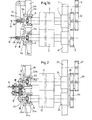
- FIG. 1 a shows somewhat schematically a part of an offset rotary printing press in which a rubber cylinder 3 is arranged between two side walls 1 and 2 and a plate cylinder 4 is arranged parallel to the latter.
- the rubber cylinder 3 and the plate cylinder 4 are mounted in the side walls 1 and 2.
- the bearings in the side wall 2 are identical to the bearings in the side wall 1 and are only indicated in principle by the reference numerals 7 and 8.
- the shaft journals of the rubber cylinder 3 and the plate cylinder 4 are mounted in bearings 5a and 6a which permit axial displacement.
- the outer bearing ring of the bearings 5a and 6a is fixed in each case with a holding part 5 and 6 arranged in the side wall 1, so that the shaft journals in the bearings 5a and 6a are rotatably and axially displaceably mounted.
- the bearing 5a is secured by the holding part 5 and by the part 5b and the bearing 6a by the holding part 6 and the part 6b against axial displacement of its outer rings.
- the inner rings of the bearings 5a and 6a are each fixedly arranged on the associated shaft journal.
- a lever 13 is pivotally articulated at its upper end on a crossbar arranged on the side wall 1.
- a threaded guide 16 is provided in the form of an internal thread or a guide nut through which a threaded spindle 14 runs.
- the right end of the threaded spindle 14 is surrounded by a connecting part 14a, which is mounted with its shaft 14b in a bearing 14c provided in the shaft journal of the rubber cylinder 3.
- a lever guide 17 is provided, through which a further threaded spindle 15 runs.
- the threaded spindle 15 can be rotated in the lever guide 17, but displacement of this in the lower end of the lever 13 in the axial direction of the threaded spindle 15 is not possible as a result of the limitations 17a and 17b preventing movement to the left and right.
- the threaded spindle 15 emerging from the lever 13 on the right is guided over a thread 18 provided in the stationary part 6b and is connected to the bearing 15a arranged in the shaft journal of the plate cylinder 4.
- the rubber cylinder 3 is displaced by a smaller amount compared to the displacement of the plate cylinder 4
- the displacement ratios are 1: 2
- the distances from the pivot point at the upper end of the lever 13 to the bearing point of the threaded spindle 14 and from the pivot point of the lever 13 to the bearing point of the threaded spindle 15 are 1: 2 behavior.
- the drive for the rubber cylinder 3 and the plate cylinder 4 is shown in the right part of FIG. 1a.
- Helical toothed drive wheels 9, 10, 11 and 12 are used to drive cylinders 3 and 4.
- the helix angles of the drive wheels 10 and 11 are opposite to one another, as can be seen from FIG. 1a.
- the two drive wheels 10 and 11 are designed as a double gear.
- a helical toothed drive wheel 12 meshes with the gear 11 and a helical toothed drive wheel 9 with the drive wheel 10.
- the drive wheel 9 can be driven, for example, by an electric motor (not shown).
- the cylinders 3 and 4 are driven by the drive wheel 9 via the drive wheel 10, which drives the rubber cylinder 3, and from the drive wheel 9 via the drive wheels 10 and 11 to the drive wheel 12, whereby the plate cylinder is driven.
- the plate cylinder 4 must be rotated, whereby, as already stated, this rotation must not be transmitted to the drive wheel 9.
- the threaded spindle 14 is rotated in the desired direction. As already explained, since the two end points of the lever 13 are fixed locally, the axial displacement caused by the rotation of the threaded spindle 14 is transmitted to the shaft journal of the rubber cylinder 3 via the connecting part 14a and the shaft 14b and via the bearing 14c. H. this is shifted left or right.
- the setting of the circumferential register of the plate cylinder 4 takes place via an axial displacement of the rubber cylinder 3 by rotation of the threaded spindle 14 and by the transmission of the rotation caused by the axial displacement of the rubber cylinder 3 due to the helical toothing of the drive wheels 9, 10 to the drive wheel 12 of the plate cylinder 4.
- the threaded spindle 15 To set the side register, the threaded spindle 15 must be rotated in the desired direction.
- the thread guide in the fixed part 6b causes an axial displacement, which is transmitted to the shaft journal of the plate cylinder via the bearing 15a.
- the plate cylinder 4 can be shifted to the left and right.
- the lever 13 As already explained, when the threaded spindle 15 is rotated, the lever 13 is carried along.
- the threaded spindle 15 mounted in a thread in the lever 13 is also axially displaced , so that an axial displacement of the blanket cylinder 3 takes place simultaneously with an axial displacement of the plate cylinder 4.
- the axial displacement of the blanket cylinder is related to the axial displacement of the plate cylinders like 1: 2.
- This simultaneous displacement of the two cylinders in the manner described above is necessary so that no rotation, ie no change in the circumferential register, is obtained when the side register is set.
- a rotation of the drive wheels 10, 11 caused by the helical toothing of the drive wheels should not turn the drive wheel 9, ie the required rotational compensation may only act on the drive wheel 12, as in the setting of the circumferential register.
- the plate cylinder 4 is shifted a total of 2x to the right (FIG. 1c).
- the drive wheel 12 must be shifted again by the amount x to the right, with this second shift by the amount x, the drive wheel 11 and thus the drive wheel 10 are not shifted, so that the drive wheel 12 is pushed to the right by the amount x of the drive wheel 11.
- the drive wheel 12 must now be rotated counterclockwise by the amount y in order to compensate for the rotation by axial displacement between the drive wheel 11 and the drive wheel 12 by the amount x.
- the drive wheel 12 did not make a revolution by an amount of 2x in the event of an axial shift to the right, while the wheels 10 and 11 only rotated counterclockwise by the amount of y in the case of an axial shift to the right were filmed.
- the rotation of the wheels 10 ′′ 11 and 12 had no influence on the drive wheel 9.
- the essential principle of the invention is thus that when the side register is set by the mutually opposing toothing of the drive wheels 10 and 11 on the axis of the rubber cylinder 3 when the rubber cylinder 3 is displaced by x in the axial direction by the helical teeth on the drive wheels 9 and 10 caused rotation is passed on, as is the case with the axial displacement between the drive wheels 11 and 12, this rotation by 2y being compensated for by the displacement of the plate cylinder 4 by the amount 2x, i.e. quasi "rotated back", so that it does not rotate, since the first rotation 2y clockwise is almost compensated for by the second rotation 2y counterclockwise.
- Fig. 2 is a slightly modified displacement device for the blanket cylinder and the plate cylinder shown.
- a rubber cylinder 21 and a plate cylinder 22 are mounted between the printing unit side walls 19 and 20.
- the cylinders 21 and 22 are driven in the same way as in FIG. 1 via a double gear wheel 28, 29 with an opposite pitch, a drive wheel 27 meshing with the gear wheel 28 and a drive wheel 30 assigned to the plate cylinder 22 meshing with the gear wheel 29.
- the cylinders 21 and 22 are supported in the side wall 20 in bearings 25 and 26.
- the left bearings of the cylinders 21 and 22 in the side wall 19 correspond to the bearings in the side wall 1 in Fig. 1. Also in Fig.
- the bearings 23a and 24a receiving the trunnions allow axial displacement
- the bearings 23a and 24a with their Outer rings are fixed in parts 23 and 24 which are fixedly connected to the side wall.
- a cover 23b which also protects the outer bearing shells of the bearing 23a against displacement and in which a thread for the displacement spindle 35 is present, is used to move the rubber cylinder 21.
- the thread in the cover 23b is indicated at 37.
- the displacement spindle 35 is mounted in a bearing 35a arranged in the shaft journal of the rubber cylinder 21, via which the force required for the axial displacement is also transmitted.
- a spindle 34 for displacing the plate cylinder 22 is guided in a thread 36 of a part 24b, which is fixedly connected to the side wall 19 or to the part 24 which secures the bearing 24a against axial displacement on the shaft journal of the plate cylinder 22 .
- the force for displacing the plate cylinder 22 in the axial direction is transmitted via the spindle 34 and the bearing 34a provided in the shaft journal.
- threaded spindle 31 To set the side register and the circumferential register, only a threaded spindle 31 is provided see. It goes without saying that the threaded spindles 14, 15 and 31 can be connected to corresponding handwheels or motor control means (not shown). 2, the threaded spindle 31 can be connected to the threaded spindle 34 via a coupling 32 and to the threaded spindle 3-5 via a coupling 33.
- the threaded spindle 35 assigned to the rubber cylinder 21 must always be in operative relation with the threaded spindle 31, if not useful for other purposes, the coupling 33 may be omitted and in its place a rigid connection between the spindle 31 and the spindle 35 can be provided.
- both the clutch 32 and the clutch 33 In order to carry out a setting of the side register, as stated, both the clutch 32 and the clutch 33 must be engaged so that both the spindle 34 and the spindle 35 are connected to the threaded spindle 31.
- the spindle 34 has a different pitch than the spindle 35.
- the spindle 34 will have a double pitch in comparison to the spindle 35. If the spindle 31 is now rotated in a certain direction, the couplings 32 and 33 and the spindles 34 and 35 shift the cylinders 21 and 22, the amount of the shift being 1: 2. If the circumferential register is to be set, the clutch 32 is disengaged. If the threaded spindle 31 is now rotated, there is only a displacement of the rubber cylinder 21.
Landscapes
- Engineering & Computer Science (AREA)
- Mechanical Engineering (AREA)
- Rotary Presses (AREA)
Applications Claiming Priority (2)
| Application Number | Priority Date | Filing Date | Title |
|---|---|---|---|
| DE19792921153 DE2921153A1 (de) | 1979-05-25 | 1979-05-25 | Vorrichtung zum einstellen des seiten- und umfangsregisters in rotationsdruckmaschinen |
| DE2921153 | 1979-05-25 |
Publications (2)
| Publication Number | Publication Date |
|---|---|
| EP0019697A1 true EP0019697A1 (fr) | 1980-12-10 |
| EP0019697B1 EP0019697B1 (fr) | 1983-05-18 |
Family
ID=6071631
Family Applications (1)
| Application Number | Title | Priority Date | Filing Date |
|---|---|---|---|
| EP80101733A Expired EP0019697B1 (fr) | 1979-05-25 | 1980-04-01 | Dispositif de réglage du repérage latéral et circonférentiel sur les machines à imprimer rotatives |
Country Status (2)
| Country | Link |
|---|---|
| EP (1) | EP0019697B1 (fr) |
| DE (2) | DE2921153A1 (fr) |
Cited By (5)
| Publication number | Priority date | Publication date | Assignee | Title |
|---|---|---|---|---|
| FR2573348A1 (fr) * | 1984-11-22 | 1986-05-23 | Hamada Printing Press | Mecanisme de reglage de la position verticale d'une forme d'impression sur une machine a imprimer |
| FR2608965A1 (fr) * | 1986-12-24 | 1988-07-01 | Roland Man Druckmasch | Groupe d'impression d'une presse d'imprimerie rotative offset a bobine pour impressions variables |
| US5092242A (en) * | 1989-06-03 | 1992-03-03 | Man Roland Druckmaschinen Ag | Lateral and circumferential register adjustment system for a rotary printing machine |
| FR2682637A1 (fr) * | 1991-10-19 | 1993-04-23 | Koenig & Bauer Ag | Dispositif de reglage du reperage dans le sens peripherique sur des machines a imprimer rotatives. |
| GB2294008A (en) * | 1994-10-13 | 1996-04-17 | Heidelberger Druckmasch Ag | A printing press plate-cylinder bearing arrangement |
Families Citing this family (5)
| Publication number | Priority date | Publication date | Assignee | Title |
|---|---|---|---|---|
| DE3117663C2 (de) | 1981-05-05 | 1984-09-20 | M.A.N.- Roland Druckmaschinen AG, 6050 Offenbach | Rollenrotationsdruckmaschine |
| DE3228476A1 (de) * | 1982-07-30 | 1984-02-09 | Kurt G. Dipl.-Ing. Hinterkopf (FH), 7332 Eislingen | Einrichtung zum verstellen einer klischeewalze eines druckwerkes z. b. fuer tubenbedruckmaschinen |
| DE3409194A1 (de) * | 1984-03-14 | 1985-09-26 | Heidelberger Druckmaschinen Ag, 6900 Heidelberg | Registerstellvorrichtung fuer eine rotationsdruckmaschine |
| DE4401344A1 (de) * | 1994-01-18 | 1995-07-20 | Roland Man Druckmasch | Verfahren und Vorrichtung zum Einstellen des Seitenregisters |
| DE4436628C1 (de) * | 1994-10-13 | 1996-04-11 | Koenig & Bauer Albert Ag | Vorrichtung zur Messung einer Durchbiegung eines Zylinders einer Rotationsdruckmaschine |
Citations (2)
| Publication number | Priority date | Publication date | Assignee | Title |
|---|---|---|---|---|
| FR991139A (fr) * | 1944-04-03 | 1951-10-01 | Marinoni | Perfectionnement apporté aux machines à imprimer |
| DE2720313A1 (de) * | 1976-07-02 | 1978-01-05 | Polygraph Leipzig | Registereinstellvorrichtung fuer formzylinder von rotationsdruckmaschinen |
-
1979
- 1979-05-25 DE DE19792921153 patent/DE2921153A1/de not_active Withdrawn
-
1980
- 1980-04-01 EP EP80101733A patent/EP0019697B1/fr not_active Expired
- 1980-04-01 DE DE8080101733T patent/DE3063255D1/de not_active Expired
Patent Citations (2)
| Publication number | Priority date | Publication date | Assignee | Title |
|---|---|---|---|---|
| FR991139A (fr) * | 1944-04-03 | 1951-10-01 | Marinoni | Perfectionnement apporté aux machines à imprimer |
| DE2720313A1 (de) * | 1976-07-02 | 1978-01-05 | Polygraph Leipzig | Registereinstellvorrichtung fuer formzylinder von rotationsdruckmaschinen |
Cited By (8)
| Publication number | Priority date | Publication date | Assignee | Title |
|---|---|---|---|---|
| FR2573348A1 (fr) * | 1984-11-22 | 1986-05-23 | Hamada Printing Press | Mecanisme de reglage de la position verticale d'une forme d'impression sur une machine a imprimer |
| FR2608965A1 (fr) * | 1986-12-24 | 1988-07-01 | Roland Man Druckmasch | Groupe d'impression d'une presse d'imprimerie rotative offset a bobine pour impressions variables |
| GB2205070A (en) * | 1986-12-24 | 1988-11-30 | Roland Man Druckmasch | Connection and registration of printing units |
| GB2205070B (en) * | 1986-12-24 | 1991-01-30 | Roland Man Druckmasch | A rotary printing machine with selectively connectible printing units |
| US5092242A (en) * | 1989-06-03 | 1992-03-03 | Man Roland Druckmaschinen Ag | Lateral and circumferential register adjustment system for a rotary printing machine |
| FR2682637A1 (fr) * | 1991-10-19 | 1993-04-23 | Koenig & Bauer Ag | Dispositif de reglage du reperage dans le sens peripherique sur des machines a imprimer rotatives. |
| GB2294008A (en) * | 1994-10-13 | 1996-04-17 | Heidelberger Druckmasch Ag | A printing press plate-cylinder bearing arrangement |
| GB2294008B (en) * | 1994-10-13 | 1998-02-18 | Heidelberger Druckmasch Ag | A printing press plate-cylinder bearing arrangement |
Also Published As
| Publication number | Publication date |
|---|---|
| DE3063255D1 (en) | 1983-07-07 |
| EP0019697B1 (fr) | 1983-05-18 |
| DE2921153A1 (de) | 1980-12-04 |
Similar Documents
| Publication | Publication Date | Title |
|---|---|---|
| EP0741015B1 (fr) | Dispositif pour régler la position circonférentielle et latérale du cylindre porte-plaque | |
| DE4103160C2 (de) | Falzapparat mit einem verstellbare Elemente, insbesondere Falzklappen oder bogenförmige Segmente, aufweisenden Falzwerkzylinder | |
| EP0154836B1 (fr) | Dispositif de répérage pour rotatives d'impression | |
| DE2818662A1 (de) | Rotationsdruckmaschine mit einrichtungen zur einstellung der positionen der druckplatten auf den plattenzylindern | |
| DE60132295T2 (de) | Unabhängiges Zylinderansteuersystem für eine lithographische Mehrfarbenpresse | |
| DE3435487A1 (de) | Vorrichtung zum voreinstellen von plattenzylindern fuer die registereinstellung in einer offset-druckpresse | |
| EP0465789A1 (fr) | Unité d'impression avec des moyens pour remplacer la plaque d'impression à la volée | |
| DE60132649T2 (de) | Vorrichtung zur Feineinstellung der Position eines Plattenzylinders für die Ausrichtung eines Mehrfarbenbildes | |
| EP0019697B1 (fr) | Dispositif de réglage du repérage latéral et circonférentiel sur les machines à imprimer rotatives | |
| EP0340428B1 (fr) | Transmission intermédiaire pour transférer un mouvement rotatif dans le va-et-vient d'un rouleau dans le dispositif d'encrage et/ou de mouillage des imprimeries rotatives | |
| EP0453868B1 (fr) | Dispositif pour ajuster les clapets de pliage d'un cylindre à clapets de pliage | |
| DE7634679U1 (de) | Vorrichtung an rotationsdruckmaschinen zum einstellen des seiten- und des umfangsregisters | |
| DE10202385A1 (de) | Druckwerk mit variabler Drucklänge und Umfangsregisterverstellung | |
| DE4404752C2 (de) | Vorrichtung zum Verstellen der Falzklappen eines Falzklappenzylinders | |
| EP0722831A2 (fr) | Procédé et arrangement pour un moteur électrique pour entraîner un corps de rotation, en particulier un cylindre d'imprimerie | |
| EP0480879B2 (fr) | Dispositif de réglage continu du mouvement de distribution axial de rouleaux distributeurs | |
| DE2531081A1 (de) | Lenk- oder steuergetriebe | |
| DE4436584C2 (de) | Plattenzylinderlagerung | |
| DE4218067C2 (de) | Druckpresse vom Drucktuch-zu-Drucktuch-Typ unter Verwendung von geteilten Plattenzylindern | |
| DE2028387A1 (de) | Vorrichtung fur die Axial und Winkeleinstellung eines Druckzylinders | |
| DE4038510A1 (de) | Registerstellvorrichtung | |
| EP2650129B1 (fr) | Unité d'impression | |
| DE1022809B (de) | Einrichtung zur Erleichterung der raeumlichen Verschiebung eines in drei rechtwinkligen Koordinatenrichtungen verschiebbaren Koerpers | |
| DE2644803A1 (de) | Bewegungsuebertragungsvorrichtung fuer ein an einem drehbaren traeger gelagertes aggregat | |
| EP1392510B1 (fr) | Procede et dispositif de reglage de registre |
Legal Events
| Date | Code | Title | Description |
|---|---|---|---|
| PUAI | Public reference made under article 153(3) epc to a published international application that has entered the european phase |
Free format text: ORIGINAL CODE: 0009012 |
|
| AK | Designated contracting states |
Designated state(s): CH DE FR GB LI SE |
|
| 17P | Request for examination filed |
Effective date: 19810121 |
|
| GRAA | (expected) grant |
Free format text: ORIGINAL CODE: 0009210 |
|
| RAP1 | Party data changed (applicant data changed or rights of an application transferred) |
Owner name: M.A.N.-ROLAND DRUCKMASCHINEN AKTIENGESELLSCHAFT |
|
| AK | Designated contracting states |
Designated state(s): CH DE FR GB LI SE |
|
| REF | Corresponds to: |
Ref document number: 3063255 Country of ref document: DE Date of ref document: 19830707 |
|
| ET | Fr: translation filed | ||
| PLBE | No opposition filed within time limit |
Free format text: ORIGINAL CODE: 0009261 |
|
| STAA | Information on the status of an ep patent application or granted ep patent |
Free format text: STATUS: NO OPPOSITION FILED WITHIN TIME LIMIT |
|
| 26N | No opposition filed | ||
| PGFP | Annual fee paid to national office [announced via postgrant information from national office to epo] |
Ref country code: GB Payment date: 19930315 Year of fee payment: 14 Ref country code: CH Payment date: 19930315 Year of fee payment: 14 |
|
| PGFP | Annual fee paid to national office [announced via postgrant information from national office to epo] |
Ref country code: FR Payment date: 19930317 Year of fee payment: 14 Ref country code: DE Payment date: 19930317 Year of fee payment: 14 |
|
| PGFP | Annual fee paid to national office [announced via postgrant information from national office to epo] |
Ref country code: SE Payment date: 19930322 Year of fee payment: 14 |
|
| PG25 | Lapsed in a contracting state [announced via postgrant information from national office to epo] |
Ref country code: GB Effective date: 19940401 |
|
| PG25 | Lapsed in a contracting state [announced via postgrant information from national office to epo] |
Ref country code: SE Effective date: 19940402 |
|
| PG25 | Lapsed in a contracting state [announced via postgrant information from national office to epo] |
Ref country code: LI Effective date: 19940430 Ref country code: CH Effective date: 19940430 |
|
| GBPC | Gb: european patent ceased through non-payment of renewal fee |
Effective date: 19940401 |
|
| PG25 | Lapsed in a contracting state [announced via postgrant information from national office to epo] |
Ref country code: FR Effective date: 19941229 |
|
| REG | Reference to a national code |
Ref country code: CH Ref legal event code: PL |
|
| PG25 | Lapsed in a contracting state [announced via postgrant information from national office to epo] |
Ref country code: DE Effective date: 19950103 |
|
| EUG | Se: european patent has lapsed |
Ref document number: 80101733.6 Effective date: 19941110 |
|
| REG | Reference to a national code |
Ref country code: FR Ref legal event code: ST |