EP0019243B1 - Stativ für Projektionsleinwände - Google Patents
Stativ für Projektionsleinwände Download PDFInfo
- Publication number
- EP0019243B1 EP0019243B1 EP80102594A EP80102594A EP0019243B1 EP 0019243 B1 EP0019243 B1 EP 0019243B1 EP 80102594 A EP80102594 A EP 80102594A EP 80102594 A EP80102594 A EP 80102594A EP 0019243 B1 EP0019243 B1 EP 0019243B1
- Authority
- EP
- European Patent Office
- Prior art keywords
- tube
- support tube
- recess
- stand
- stand according
- Prior art date
- Legal status (The legal status is an assumption and is not a legal conclusion. Google has not performed a legal analysis and makes no representation as to the accuracy of the status listed.)
- Expired
Links
- 230000000295 complement effect Effects 0.000 abstract 1
- 238000010276 construction Methods 0.000 description 1
- 238000004519 manufacturing process Methods 0.000 description 1
Images
Classifications
-
- G—PHYSICS
- G03—PHOTOGRAPHY; CINEMATOGRAPHY; ANALOGOUS TECHNIQUES USING WAVES OTHER THAN OPTICAL WAVES; ELECTROGRAPHY; HOLOGRAPHY
- G03B—APPARATUS OR ARRANGEMENTS FOR TAKING PHOTOGRAPHS OR FOR PROJECTING OR VIEWING THEM; APPARATUS OR ARRANGEMENTS EMPLOYING ANALOGOUS TECHNIQUES USING WAVES OTHER THAN OPTICAL WAVES; ACCESSORIES THEREFOR
- G03B21/00—Projectors or projection-type viewers; Accessories therefor
- G03B21/54—Accessories
- G03B21/56—Projection screens
- G03B21/58—Projection screens collapsible, e.g. foldable; of variable area
-
- F—MECHANICAL ENGINEERING; LIGHTING; HEATING; WEAPONS; BLASTING
- F16—ENGINEERING ELEMENTS AND UNITS; GENERAL MEASURES FOR PRODUCING AND MAINTAINING EFFECTIVE FUNCTIONING OF MACHINES OR INSTALLATIONS; THERMAL INSULATION IN GENERAL
- F16M—FRAMES, CASINGS OR BEDS OF ENGINES, MACHINES OR APPARATUS, NOT SPECIFIC TO ENGINES, MACHINES OR APPARATUS PROVIDED FOR ELSEWHERE; STANDS; SUPPORTS
- F16M2200/00—Details of stands or supports
- F16M2200/02—Locking means
- F16M2200/021—Locking means for rotational movement
- F16M2200/024—Locking means for rotational movement by positive interaction, e.g. male-female connections
Definitions
- the invention relates to a tripod for projection screens with a standpipe and tripod legs attached to it and a detachable connection between the standpipe and a tube containing a roll-up screen.
- connection consists of a bow-like handle, to which the tube is attached by means of a screw.
- the tube can be pivoted about the axis of the screw so that it can be aligned parallel to the standpipe when the projection screen is not used.
- the disadvantage of such known tripods is that the projection screen can only be transported and used together with the tripod. Since this arrangement is somewhat bulky, it is particularly difficult for small and weak people to transport; nor can the canvas be used on its own and without a tripod.
- Tripods have therefore also become known in which the tube and standpipe can be separated (US Pat. Nos. 3,629,910 and 3,022,816).
- these known solutions are complicated in construction and therefore expensive to manufacture.
- the invention has for its object to provide a tripod with a particularly simple connection between the standpipe and tube, which enables the easy-to-use solution of the reliably fixed connections between the standpipe and tube in the position of use.
- the connection comprises a holder arranged on the standpipe, which has a dovetail-shaped recess which can be closed with a cover plate which can be pivoted about the axis of the standpipe, and in that the tube is provided with a fastening part which can be pushed into the recess.
- This arrangement makes it possible to easily remove the canvas tube from the standpipe and to transport and use it separately.
- the pivotable cover plate for the dovetail-shaped recess ensures that the tube cannot be removed unintentionally. In order to avoid that the cover plate moves unintentionally, it can have a knob on its underside, which can be brought into engagement with a corresponding recess in the fastening part.
- the fastening part preferably has two parts lying flat against one another, one of which is fastened to the tube and the other is provided with an insert which can be pushed into the recess, both parts being passed through are bolted together.
- the abutting surface of one section can have at least one knob-like projection and the abutting surface of the other section can be provided with at least two recesses which are offset by 90 ° from one another and correspond to the projections. This enables the tube to be locked in a position which can be pivoted through 90 °.
- Four knobs and depressions arranged at right angles to one another are expediently provided.
- a slotted sleeve 2 preferably made of plastic, is slid onto the standpipe 1, which is provided with tripod legs (not shown) in a known manner and is provided with a thread 3 at the lower end, which ends in a conical surface 4.
- the threaded bore of a closed cylindrical sleeve 5 is screwed onto the thread 3, which is provided on the outside with a longitudinal corrugation 6 and which has a conical bore 7 corresponding to the conical surface 4.
- a bracket 8 On the mounting sleeve 2, a bracket 8 is attached.
- This holder 8 has a cylindrical bore which surrounds the sleeve 2.
- the holder 8 On the side, the holder 8 is provided with a dovetail-shaped recess 9, which is closed at the lower end by a base 10a. At the upper end, the recess 9 can be closed by a closure plate 10 which can be pivoted about the axis of the standpipe 1 and which is provided with a downwardly extending knob 11.
- the tube-like container 12 for the projection screen is provided with a fastening body 14 which is connected to a plate 15 in which there are four recesses 16 at an angular distance of 90 °.
- a Part provided on one side with a dovetail-shaped extension 17 has on the opposite side of this extension a plate 18 which is provided with nub-like projections 19 which can be brought into engagement with the recesses 16 in the plate 15. Both parts 15 and 18 of the fastening part are held together by a screw bolt 20. At the upper and at the lower end, the dovetail-shaped projection 17 is provided with a recess 21 for receiving the knob-like projection 11 of the fastening plate 10.
Landscapes
- Physics & Mathematics (AREA)
- General Physics & Mathematics (AREA)
- Overhead Projectors And Projection Screens (AREA)
- Accessories Of Cameras (AREA)
- Video Image Reproduction Devices For Color Tv Systems (AREA)
- Projection Apparatus (AREA)
- Cathode-Ray Tubes And Fluorescent Screens For Display (AREA)
- Tables And Desks Characterized By Structural Shape (AREA)
Description
- Die Erfindung betrifft ein Stativ für Projektionsleinwände mit einem Standrohr und an diesem befestigten Stativbeinen sowie einer lösbaren Verbindung zwischen dem Standrohr und einer eine aufrollbare Leinwand enthaltenden Tube.
- Bei bekannten Stativen dieser Art besteht die Verbindung aus einem bügelartigen Handgriff, an dem mittels einer Schraube die Tube befestigt ist. Die Tube kann hierbei um die Achse der Schraube schwenkbar sein, so daß sie parallel zum Standrohr ausgerichtet werden kann, wenn die Projektionsleinwand nicht gebraucht wird. Hierdurch wird der Raumbedarf der Anordnung bei der Aufbewahrung und Lagerung verringert. Der Nachteil derartiger bekannter Stative besteht darin, daß die Projektionsleinwand nur zusammen mit dem Stativ transportiert und verwendet werden kann. Da diese Anordnung etwas sperrig ist, läßt sie sich insbesondere von kleinen und schwachen Personen schlecht transportieren; auch läßt sich die Leinwand nicht für sich und ohne Stativ verwenden. Es sind daher auch schon Stative bekannt geworden, bei denen Tube und Standrohr getrennt werden können (US-A-3 629 910 und US-A-3 022 816). Diese bekannten Lösungen sind jedoch kompliziert im Aufbau und damit teuer in der Herstellung.
- Der Erfindung liegt die Aufgabe zugrunde, ein Stativ mit einer besonders einfachen Verbindung zwischen Standrohr und Tube zu schaffen, die die leicht zu handhabende Lösung der in Gebrauchsstellung zuverlässig festen Verbindungen zwischen Standrohr und Tube ermöglicht. Dies wird dadurch erreicht, daß die Verbindung eine am Standrohr angeordnete Halterung umfaßt, die eine schwalbenschwanzförmige Ausnehmung aufweist, welche mit einer um die Achse des Standrohrs schwenkbaren Abdeckplatte verschießbar ist, und daß die Tube mit einem in die Ausnehmung einschiebbaren Befestigungsteil versehen ist. Durch diese Anordnung ist es möglich, die Leinwandtube ohne weiteres vom Standrohr abzunehmen und sie getrennt zu transportieren und zu verwenden. Durch die schwenkbare Abdeckplatte für die schwalbenschwanzförmige Ausnehmung wird erreicht, daß die Tube nicht unbeabsichtigt abgenommen werden kann. Um zu vermeiden, daß die Abdeckplatte sich unbeabsichtigt verschiebt, kann sie an ihrer Unterseite eine Noppe aufweisen, die mit einer korrespondierenden Vertiefung in dem Befestigungsteil in Eingriff bringbar ist.
- Um eine Verschwenkung der Tube parallel zur Achse des Standrohrs und quer dazu zu ermöglichen, weist das Befestigungsteil vorzugsweise zwei flächig aneinanderliegende Teilstücke auf, von denen eines an der Tube befestigt und das andere mit einem in die Ausnehmung einschiebbaren Ansatz versehen ist, wobei beide Teilstükke durch einen Bolzen miteinander verbunden sind. Hierbei kann die anliegende Fläche des einen Teilstücks mindestens einen noppenartigen Vorsprung aufweisen und die anliegende Fläche des anderen Teilstücks mit mindestens zwei um 90° gegeneinander versetzten, mit den Vorsprüngen korrespondierenden Ausnehmungen versehen sein. Hierdurch wird ermöglicht, daß die Tube in einer um 90° verschwenkbaren Stellung verrastbar ist. Zweckmäßigerweise werden vier im rechten Winkel zueinander angeordnete Noppen und Vertiefungen vorgesehen.
- Gemäß einer vorteilhaften Weiterbildung der Erfindung ist die Halterung nicht an einem Handgriff befestigt, sondern auf einer das Standrohr umfassenden geschlitzten Hülse angeordnet, die an ihrem unteren Ende ein Gewinde aufweist, welches in eine Kegelfläche übergeht. Ferner ist ein zylindrisches Feststellteil vorgesehen, das ebenfalls das Standrohr umfaßt und dessen eines Ende mit einer in das Gewinde eingreifenden Gewindebohrung versehen ist, welche in eine an der Kegelfläche anliegende konische Bohrung ausläuft. Hierdurch ist eine einfache und formschöne Anordnung als Griff zum Transport und als Verstellvorrichtung zur Verschiebung der Tube am Standrohr gegeben.
- Weitere Einzelheiten und Vorteile der Erfindung können dem in der Zeichnung dargestellten Ausführungsbeispiel entnommen werden. Es zeigt
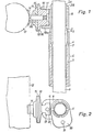
- Fig. 1 einen Längsschnitt durch das erfindungsgemäße Stativ im Bereich der Befestigungsvorrichtung;
- Fig. 2 eine Draufsicht auf die in Fig. 1 dargestellte Vorrichtung.
- Auf das in bekannter Weise am unteren Ende mit (nicht dargestellten) Stativbeinen versehene Standrohr 1 ist eine vorzugsweise aus Kunststoff bestehende geschlitzte Hülse 2 aufgeschoben, die am unteren Ende mit einem Gewinde 3 versehen ist, welches in eine Kegelfläche 4 ausläuft. Auf das Gewinde 3 ist die Gewindebohrung einer geschlossenen zylindrischen Hülse 5 aufgeschraubt, die an der Außenseite mit einer Längsriffelung 6 versehen ist und die eine der Kegelfläche 4 entsprechende konische Bohrung 7 aufweist.
- Auf der Befestigungshülse 2 ist eine Halterung 8 befestigt. Diese Halterung 8 weist eine zylindrische Bohrung auf, die die Hülse 2 umschließt. An der Seite ist die Halterung 8 mit einer schwalbenschwanzförmigen Ausnehmung 9 versehen, die am unteren Ende durch einen Boden 10a abgeschlossen ist. Am oberen Ende ist die Ausnehmung 9 durch eine um die Achse des Standrohrs 1 schwenkbare Verschlußplatte 10 verschließbar, die mit einer sich nach unten erstreckenden Noppe 11 versehen ist. Der tubenartige Behälter 12 für die Projektionsleinwand ist mit einem Befestigungskörper 14 versehen, der mit einer Platte 15 verbunden ist, in der sich vier Ausnehmungen 16 im Winkelabstand von 90° befinden. Ein an einer Seite mit einem schwalbenschwanzförmigen Ansatz 17 versehenes Teil weist an der diesem Ansatz entgegengesetzten Seite eine Platte 18 auf, die mit noppenartigen Vorsprüngen 19 versehen ist, welche mit den Ausnehmungen 16 in der Platte 15 in Eingriff bringbar sind. Beide Teile 15 und 18 des Befestigungsteils sind durch einen Schraubenbolzen 20 zusammengehalten. Am oberen und am unteren Ende ist der schwalbenschwanzförmige Vorsprung 17 mit einer Ausnehmung 21 für die Aufnahme des noppenartigen Vorsprungs 11 der Befestigungsplatte 10 versehen.
- Die Halterung 8 und die Abdeckplatte 10 lassen sich besonders einfach auf der Hülse 2 dadurch montieren, daß beide Teile über die am oberen Ende der Hülse 2 vorgesehenen angeschrägten Kanten 2A geschoben werden, solange die Hülse 2 noch nicht auf dem Standrohr 1 montiert ist. Durch die vorstehenden Kanten 2B sind beide Teile gegen Herausfallen gesichert. Die Verbindungsvorrichtung läßt sich dadurch längs des Standrohrs 1 verschieben, daß die Hülse 5 entgegen dem Uhrzeigersinn gedreht wird. Hierdurch wird die kegelförmige Ausnehmung 7 auf der Kegelfläche 4 nach unten verschoben und gelockert. Die Hülse 2 läßt sich danach in Richtung der Achse des Standrohrs 1 in eine beliebige Lage verschieben.
- Um die Leinwandtube für den Transport des Stativs aus Gewichts- oder Raumgründen von diesem abzunehmen, wird die Abdeckplatte 10 in die in Fig. 2 dargestellte Lage gebracht, nachdem die Noppe 11 elastisch aus der Ausnehmung 21 herausgeschoben worden ist. Danach läßt sich die Tube 12 mit ihrem Ansatz 17 aus der schwalbenschwanzförmigen Ausnehmung 9 herausheben.
- Zur kurzfristigen Verkleinerung des Raumbedarfs der Anordnung ist die Tube außerdem um die Achse des Schraubenbolzens 20 in eine jeweils um 90° verschiedene Lage verschwenkbar, indem die Noppen 18 elastisch aus den Ausnehmungen 19 aus- und in der gewünschten Endlage wieder einrasten.
Claims (6)
Priority Applications (1)
| Application Number | Priority Date | Filing Date | Title |
|---|---|---|---|
| AT80102594T ATE6098T1 (de) | 1979-05-11 | 1980-05-09 | Stativ fuer projektionsleinwaende. |
Applications Claiming Priority (2)
| Application Number | Priority Date | Filing Date | Title |
|---|---|---|---|
| DE19792919170 DE2919170A1 (de) | 1979-05-11 | 1979-05-11 | Stativ fuer projektionsleinwaende |
| DE2919170 | 1979-05-11 |
Publications (2)
| Publication Number | Publication Date |
|---|---|
| EP0019243A1 EP0019243A1 (de) | 1980-11-26 |
| EP0019243B1 true EP0019243B1 (de) | 1984-02-01 |
Family
ID=6070556
Family Applications (1)
| Application Number | Title | Priority Date | Filing Date |
|---|---|---|---|
| EP80102594A Expired EP0019243B1 (de) | 1979-05-11 | 1980-05-09 | Stativ für Projektionsleinwände |
Country Status (5)
| Country | Link |
|---|---|
| US (1) | US4340198A (de) |
| EP (1) | EP0019243B1 (de) |
| JP (1) | JPS5610893A (de) |
| AT (1) | ATE6098T1 (de) |
| DE (2) | DE2919170A1 (de) |
Families Citing this family (5)
| Publication number | Priority date | Publication date | Assignee | Title |
|---|---|---|---|---|
| US4518191A (en) * | 1982-02-22 | 1985-05-21 | Deflecta-Shield Corporation | Air current deflector shield and bracket combination |
| FR2583964B1 (fr) * | 1985-06-28 | 1987-09-11 | Massonnet Henry | Systeme de roue rapidement demontable par rapport a un support |
| JP3791907B2 (ja) * | 2002-02-12 | 2006-06-28 | オリンパス株式会社 | 観察装置 |
| DE102011077356A1 (de) * | 2011-06-10 | 2012-12-13 | Projektor Ag | Vorrichtung für eine hängende befestigung eines projektors |
| CN109278804B (zh) * | 2018-08-15 | 2020-04-14 | 中车青岛四方机车车辆股份有限公司 | 显示屏安装结构及具有其的列车 |
Family Cites Families (11)
| Publication number | Priority date | Publication date | Assignee | Title |
|---|---|---|---|---|
| US1073477A (en) * | 1911-02-01 | 1913-09-16 | Dietz Co R E | Lamp-socket. |
| US2156862A (en) * | 1935-03-20 | 1939-05-02 | Maugard Adolfo Best | Mount for cinema cameras, etc. |
| US2459676A (en) * | 1948-01-12 | 1949-01-18 | Harold J Axtell | Universal coupler for supporting cameras on tripods |
| DE919321C (de) * | 1952-11-06 | 1954-10-18 | Mechanische Weberei G M B H | Transportable Projektionswand fuer Filmvorfuehrungen od. dgl. |
| US2763453A (en) * | 1953-05-07 | 1956-09-18 | Palino Anthony | Collapsible rod holder |
| DE1121839B (de) * | 1958-03-20 | 1962-01-11 | Artur Fischer | Aufrollbarer Bildschirm |
| US3022816A (en) * | 1959-03-13 | 1962-02-27 | Knox Mfg Company | Portable movie screen |
| DE1256901B (de) * | 1962-11-16 | 1967-12-21 | Otto Hahn | Vorrichtung zum Schnellbefestigen von Kameras od. dgl. auf Stativen |
| US3389883A (en) * | 1966-03-04 | 1968-06-25 | Solo Cup Co | Dispenser mounting means |
| GB1195369A (en) * | 1966-12-08 | 1970-06-17 | Engineering Developments Birmi | Improvements in, or relating to, Couplings for Tubes, Bars and the like |
| US3629910A (en) * | 1969-11-28 | 1971-12-28 | Graflex Inc | Handle assembly for picture projection screen |
-
1979
- 1979-05-11 DE DE19792919170 patent/DE2919170A1/de not_active Withdrawn
-
1980
- 1980-05-09 JP JP6160480A patent/JPS5610893A/ja active Pending
- 1980-05-09 EP EP80102594A patent/EP0019243B1/de not_active Expired
- 1980-05-09 AT AT80102594T patent/ATE6098T1/de not_active IP Right Cessation
- 1980-05-09 DE DE8080102594T patent/DE3066354D1/de not_active Expired
- 1980-05-09 US US06/148,123 patent/US4340198A/en not_active Expired - Lifetime
Also Published As
| Publication number | Publication date |
|---|---|
| ATE6098T1 (de) | 1984-02-15 |
| EP0019243A1 (de) | 1980-11-26 |
| DE2919170A1 (de) | 1980-11-20 |
| DE3066354D1 (en) | 1984-03-08 |
| JPS5610893A (en) | 1981-02-03 |
| US4340198A (en) | 1982-07-20 |
Similar Documents
| Publication | Publication Date | Title |
|---|---|---|
| EP0263974A2 (de) | Schnellverschluss mit einem Anschlussteil eines Anbauteils für transportable Grossbehälter, insbesondere eines Anbauteils von einer Hub- bzw. Absetzvorrichtung für solche Grossbehälter, z.B. Container, Shelter, Kabinen oder dergleichen | |
| EP0019243B1 (de) | Stativ für Projektionsleinwände | |
| AT399261B (de) | Frontblendenhalterung für schubladen | |
| DE202020001533U1 (de) | Gehvorrichtung zum Begehen von Solarmodulen | |
| EP2789975A1 (de) | Absteckmarker | |
| DE2814931A1 (de) | Haltevorrichtung fuer eine dreidimensionale struktur | |
| DE102018118772B4 (de) | Stecknusshalterahmenbaugruppe | |
| DE4212412C2 (de) | Vorrichtung zur höhenverstellbaren Anordung von Bürogeräten oder -möbelteilen | |
| DE2656872C2 (de) | Ständer mit verstellbarem Schrägarm | |
| DE3431438A1 (de) | Vorrichtung zur anordnung von behaeltnissen | |
| DE3145942C2 (de) | "Arbeitstisch mit Tischgestell und Arbeitsplatte" | |
| DE934549C (de) | Kopfstueck fuer Stative | |
| DE9108075U1 (de) | Anbaufähiges Regal mit verbindbaren Stangen | |
| DE2908811C2 (de) | Vorrichtung zur Befestigung von Gerätekoffern in Gestellen | |
| DE3620699A1 (de) | Aufspannvorrichtung | |
| DE20002165U1 (de) | Feldstaffelei | |
| DE2843842A1 (de) | Einspanneinrichtung, vorzugsweise zum zusammenhalten von werkstuecken | |
| DE4428390A1 (de) | Tischuntergestellsystem zur Aufnahme und zum Befestigen einer Tischplatte | |
| EP0072570A2 (de) | Projektionstisch | |
| EP0083795B1 (de) | Transportable Projektionsleinwand | |
| DE2306429A1 (de) | Stativ fuer fotografische zwecke | |
| DE2306932A1 (de) | Einbeinstativ | |
| DE9111918U1 (de) | Angelgerät | |
| DE1069394B (de) | Stativ-Neigekopf mit schwenkbarem Stielgriff | |
| DE202019002339U1 (de) | Halterung zur lösbaren Befestigung von Zubehörteilen an einer Längsstange eines Zweirades |
Legal Events
| Date | Code | Title | Description |
|---|---|---|---|
| PUAI | Public reference made under article 153(3) epc to a published international application that has entered the european phase |
Free format text: ORIGINAL CODE: 0009012 |
|
| AK | Designated contracting states |
Designated state(s): AT BE CH DE FR GB IT LU NL SE |
|
| 17P | Request for examination filed |
Effective date: 19810518 |
|
| GRAA | (expected) grant |
Free format text: ORIGINAL CODE: 0009210 |
|
| AK | Designated contracting states |
Designated state(s): AT BE CH DE FR GB IT LI LU NL SE |
|
| PG25 | Lapsed in a contracting state [announced via postgrant information from national office to epo] |
Ref country code: SE Effective date: 19840201 Ref country code: IT Free format text: LAPSE BECAUSE OF FAILURE TO SUBMIT A TRANSLATION OF THE DESCRIPTION OR TO PAY THE FEE WITHIN THE PRESCRIBED TIME-LIMIT;WARNING: LAPSES OF ITALIAN PATENTS WITH EFFECTIVE DATE BEFORE 2007 MAY HAVE OCCURRED AT ANY TIME BEFORE 2007. THE CORRECT EFFECTIVE DATE MAY BE DIFFERENT FROM THE ONE RECORDED. Effective date: 19840201 Ref country code: BE Effective date: 19840201 |
|
| REF | Corresponds to: |
Ref document number: 6098 Country of ref document: AT Date of ref document: 19840215 Kind code of ref document: T |
|
| REF | Corresponds to: |
Ref document number: 3066354 Country of ref document: DE Date of ref document: 19840308 |
|
| PG25 | Lapsed in a contracting state [announced via postgrant information from national office to epo] |
Ref country code: LU Free format text: LAPSE BECAUSE OF NON-PAYMENT OF DUE FEES Effective date: 19840531 |
|
| PGFP | Annual fee paid to national office [announced via postgrant information from national office to epo] |
Ref country code: NL Payment date: 19840601 Year of fee payment: 5 Ref country code: AT Payment date: 19840601 Year of fee payment: 5 |
|
| ET | Fr: translation filed | ||
| PGFP | Annual fee paid to national office [announced via postgrant information from national office to epo] |
Ref country code: CH Payment date: 19840626 Year of fee payment: 5 |
|
| PGFP | Annual fee paid to national office [announced via postgrant information from national office to epo] |
Ref country code: DE Payment date: 19841023 Year of fee payment: 5 |
|
| PLBE | No opposition filed within time limit |
Free format text: ORIGINAL CODE: 0009261 |
|
| STAA | Information on the status of an ep patent application or granted ep patent |
Free format text: STATUS: NO OPPOSITION FILED WITHIN TIME LIMIT |
|
| GBPC | Gb: european patent ceased through non-payment of renewal fee | ||
| PG25 | Lapsed in a contracting state [announced via postgrant information from national office to epo] |
Ref country code: FR Free format text: LAPSE BECAUSE OF NON-PAYMENT OF DUE FEES Effective date: 19850131 |
|
| 26N | No opposition filed | ||
| REG | Reference to a national code |
Ref country code: FR Ref legal event code: ST |
|
| PG25 | Lapsed in a contracting state [announced via postgrant information from national office to epo] |
Ref country code: AT Effective date: 19850509 |
|
| PG25 | Lapsed in a contracting state [announced via postgrant information from national office to epo] |
Ref country code: LI Effective date: 19850531 Ref country code: CH Effective date: 19850531 |
|
| PG25 | Lapsed in a contracting state [announced via postgrant information from national office to epo] |
Ref country code: NL Effective date: 19851201 |
|
| NLV4 | Nl: lapsed or anulled due to non-payment of the annual fee | ||
| REG | Reference to a national code |
Ref country code: CH Ref legal event code: PL |
|
| PG25 | Lapsed in a contracting state [announced via postgrant information from national office to epo] |
Ref country code: DE Effective date: 19860201 |
|
| PG25 | Lapsed in a contracting state [announced via postgrant information from national office to epo] |
Ref country code: GB Effective date: 19881118 |