EP0015490A1 - Elément chauffant électrique - Google Patents
Elément chauffant électrique Download PDFInfo
- Publication number
- EP0015490A1 EP0015490A1 EP80100960A EP80100960A EP0015490A1 EP 0015490 A1 EP0015490 A1 EP 0015490A1 EP 80100960 A EP80100960 A EP 80100960A EP 80100960 A EP80100960 A EP 80100960A EP 0015490 A1 EP0015490 A1 EP 0015490A1
- Authority
- EP
- European Patent Office
- Prior art keywords
- heating element
- element according
- heating
- space
- cooking
- Prior art date
- Legal status (The legal status is an assumption and is not a legal conclusion. Google has not performed a legal analysis and makes no representation as to the accuracy of the status listed.)
- Granted
Links
- 238000005485 electric heating Methods 0.000 title claims abstract description 8
- 238000010438 heat treatment Methods 0.000 claims abstract description 80
- 238000010411 cooking Methods 0.000 claims abstract description 26
- 229910052751 metal Inorganic materials 0.000 claims abstract description 19
- 239000002184 metal Substances 0.000 claims abstract description 19
- 235000013305 food Nutrition 0.000 claims abstract description 7
- 238000009413 insulation Methods 0.000 claims description 6
- 230000000694 effects Effects 0.000 claims description 2
- 239000012528 membrane Substances 0.000 claims description 2
- 239000007788 liquid Substances 0.000 abstract 2
- 230000000284 resting effect Effects 0.000 abstract 1
- 238000005476 soldering Methods 0.000 description 8
- 239000002241 glass-ceramic Substances 0.000 description 7
- 239000011810 insulating material Substances 0.000 description 4
- 229910001220 stainless steel Inorganic materials 0.000 description 4
- 239000010935 stainless steel Substances 0.000 description 4
- 238000004519 manufacturing process Methods 0.000 description 3
- 239000000463 material Substances 0.000 description 3
- 238000000034 method Methods 0.000 description 3
- 229910052782 aluminium Inorganic materials 0.000 description 2
- XAGFODPZIPBFFR-UHFFFAOYSA-N aluminium Chemical compound [Al] XAGFODPZIPBFFR-UHFFFAOYSA-N 0.000 description 2
- 239000002131 composite material Substances 0.000 description 2
- 239000004020 conductor Substances 0.000 description 2
- 229910000679 solder Inorganic materials 0.000 description 2
- RYGMFSIKBFXOCR-UHFFFAOYSA-N Copper Chemical compound [Cu] RYGMFSIKBFXOCR-UHFFFAOYSA-N 0.000 description 1
- 208000000260 Warts Diseases 0.000 description 1
- 230000015572 biosynthetic process Effects 0.000 description 1
- 238000010276 construction Methods 0.000 description 1
- 229910052802 copper Inorganic materials 0.000 description 1
- 239000010949 copper Substances 0.000 description 1
- 238000005260 corrosion Methods 0.000 description 1
- 230000007797 corrosion Effects 0.000 description 1
- 230000003670 easy-to-clean Effects 0.000 description 1
- 239000011888 foil Substances 0.000 description 1
- 239000008187 granular material Substances 0.000 description 1
- 238000007373 indentation Methods 0.000 description 1
- 239000012784 inorganic fiber Substances 0.000 description 1
- 238000002844 melting Methods 0.000 description 1
- 230000008018 melting Effects 0.000 description 1
- 239000007769 metal material Substances 0.000 description 1
- 230000003647 oxidation Effects 0.000 description 1
- 238000007254 oxidation reaction Methods 0.000 description 1
- 239000000843 powder Substances 0.000 description 1
- 201000010153 skin papilloma Diseases 0.000 description 1
- 239000007787 solid Substances 0.000 description 1
- 125000006850 spacer group Chemical group 0.000 description 1
Images


Classifications
-
- H—ELECTRICITY
- H05—ELECTRIC TECHNIQUES NOT OTHERWISE PROVIDED FOR
- H05B—ELECTRIC HEATING; ELECTRIC LIGHT SOURCES NOT OTHERWISE PROVIDED FOR; CIRCUIT ARRANGEMENTS FOR ELECTRIC LIGHT SOURCES, IN GENERAL
- H05B3/00—Ohmic-resistance heating
- H05B3/68—Heating arrangements specially adapted for cooking plates or analogous hot-plates
- H05B3/688—Fabrication of the plates
-
- H—ELECTRICITY
- H05—ELECTRIC TECHNIQUES NOT OTHERWISE PROVIDED FOR
- H05B—ELECTRIC HEATING; ELECTRIC LIGHT SOURCES NOT OTHERWISE PROVIDED FOR; CIRCUIT ARRANGEMENTS FOR ELECTRIC LIGHT SOURCES, IN GENERAL
- H05B3/00—Ohmic-resistance heating
- H05B3/68—Heating arrangements specially adapted for cooking plates or analogous hot-plates
- H05B3/72—Plates of sheet metal
-
- Y—GENERAL TAGGING OF NEW TECHNOLOGICAL DEVELOPMENTS; GENERAL TAGGING OF CROSS-SECTIONAL TECHNOLOGIES SPANNING OVER SEVERAL SECTIONS OF THE IPC; TECHNICAL SUBJECTS COVERED BY FORMER USPC CROSS-REFERENCE ART COLLECTIONS [XRACs] AND DIGESTS
- Y10—TECHNICAL SUBJECTS COVERED BY FORMER USPC
- Y10T—TECHNICAL SUBJECTS COVERED BY FORMER US CLASSIFICATION
- Y10T29/00—Metal working
- Y10T29/53—Means to assemble or disassemble
- Y10T29/5313—Means to assemble electrical device
- Y10T29/53191—Means to apply vacuum directly to position or hold work part
Definitions
- the invention relates to an electric heating element for heating food or the like.
- Cooking plates are usually used for this purpose, on the heating surface of which cooking vessels are placed.
- Cooking elements have also become known which consist of spirally arranged tubular heating elements which have a triangular cross section with an enlarged upper contact surface on which the cooking vessels are placed.
- Such hot plates are for example from GB-PS 76 78 87 and DE-OS 27 51 991 (corresponding to US patent application Ser.No. 961 837, filed November 17, 1978, inventor: Gerhard G Griffinler). Because of their low heat capacity, they have a very high degree of efficiency, especially during the parboiling process. However, it is often perceived as annoying that the radiators are open and difficult to clean. Furthermore, in the version according to GB-PS 76 78 87, the hotplate is permeable to overflowing cookware, which is very disadvantageous.
- the US-PS 22 99 596 describes an embodiment in which trapezoidal heating strips are connected via trapezoidal spacers to a largely flat plate. However, this plate is difficult to manufacture and could not prevail in practice.
- glass-ceramic stoves in which the cooking surface consists of a glass-ceramic plate and which is heated from below by spiral-shaped tubular heating elements in a triangular shape by contact heating will.
- these glass ceramic plates have the advantage of a closed upper cooking surface, which can possibly extend over several hotplates, they have the disadvantage that the glass ceramic plate is a poor heat conductor and thus the heat transfer from the bottom to the top and the heat distribution is poor are.
- the heating elements have to be brought to very high temperatures in order to assert sufficient energy and the exact regulation of this temperature creates difficulties.
- the vacuum is used in any case to place the tubular heater on the underside of the upper part, which is without grooves and essentially smooth.
- a soldering is carried out between the tubular heating element and the upper part under vacuum, the vacuum on the one hand ensuring the good system and on the other hand ensuring perfect soldering.
- the vacuum can then be maintained in the room, although this is not absolutely necessary.
- the air pressure which acts on the evacuated space in conjunction with a resilient design of the upper and / or lower part ensures that the tubular heating element is connected to the underside of the upper part in thermally conductive contact is created. It is also possible to insert insulation between the tubular heater and the lower part. It is also advantageous to have the tubular heating element supported on an internal support plate if the upper part is flexible. This ensures, despite a very flexible and adaptable upper part, that the tubular heating element spiral provided in most cases remains flat and level.
- the electrical heating element 11 shown in FIG. 1 consists of stainless steel sheet (0.3-0.6 mm thick) and has an upper part 12 which has a flat, annular heating surface 13, a circumferential, laterally shaped flange 14, and a downwardly directed annular edge 15 and contains an inner, also annular rim 16.
- a cylindrical sleeve 20 is inserted, which has an upper and lower flange and a temperature sensor socket, for example, the movable sensor can 40 of an automatic temperature controller 41.
- a sheet metal ring 21 is supported against the flange 14 and forms an overhang edge 21 which is supported on a hotplate or hob 44.
- tubular heating elements 23 are arranged in a spiral.
- the tubular heaters have a metallic jacket and heating resistors lying in an embedding.
- the jacket is deformed into a triangle, so that the tubular heating elements 23 bear with their upper, essentially flat triangular side on the heating surface 12 from the inside, while they have only a linear contact on the lower part in the area of the triangular corner.
- the tubular heating elements 43 are sealed through a downwardly directed grommet 42 of the lower part.
- connection between the upper and lower part and the tubular heating element is done by soldering on the vacuum.
- a solder foil or a solder powder is placed between the sheet metal parts and the tubular heating element and after evacuation of the space 22, the soldering is carried out by heating the unit.
- the heating can also take place inductively. This creates a very stable hotplate that does not tend to warp. If the tubular heating elements are also soldered to the lower part, a rigid sandwich structure is created.
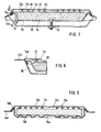
- FIG. 2 An embodiment is shown in which a wart-shaped, upwardly directed formation 24 is provided in the lower part 17 ', which ensures a spacing between the upper and lower parts during soldering.
- the support elements 24 can also be provided in the upper part or in the upper and lower part.
- the outer flange 14 had a lower, essentially flat surface and an adjoining bevel which leads to the cooking surface 13.
- the flange is formed as a bend in the sheet of the heating surface by 180 °. This flange can rest on the surface of the hob, either directly or with an overflow rim.
- inwardly directed indentations 26 are provided both in the upper and lower part, each lying between the tubular heating elements and therefore normally forming a spiral pattern on the upper and lower sides. These impressions stiffen the surfaces on the one hand, but allow expansion in the radial direction. It is particularly advantageous if these impressions are impressed during an alignment process following the soldering.
- the embodiment according to FIG. 4 also has impressions 26, but only in the area of the upper part.
- the flange 14 ' is directed outwards and obliquely downwards and consists of the soldered or welded edges of the upper and lower part 12' ', 17 ". It thereby forms the overflow edge itself.
- FIG. 5 shows a heating element 11b which corresponds in its basic structure to that of FIG. 1.
- both the upper part 12 b and the lower part 17 b are curved so that the cooking surface 13 b has a concave shape.
- a cooking vessel 36 with a curved bottom, for example a Chinese wok, can be guided in this.
- the curved design creates additional stiffening.
- the middle sensor opening ensures additional cohesion between the upper and lower part.
- FIG. 6 shows a kettle 31 which has a vessel 32 with a lid and spout and a bottom 33 which is formed by the upper part 12 a of the heating element, which is received in a housing 34 in the form of an upwardly open bowl, that stands on feet.
- the upper part 12 a forms the vessel wall or the vessel bottom, while the lower part 17 a is soldered to it.
- the cover and the heating surface are directed upwards and soldered to the wall of the vessel 32.
- the tubular heating elements 23 are soldered in under vacuum.
- the unit comprising the vessel and the heating element is fastened to the housing 34 by a screw bolt 35.
- Fig. 7 a particularly preferred embodiment of an electric heating element is shown, in which the upper part 12 c consists of a very thin sheet of stainless steel in the order of 0.2 to 0.3 mm thick. This sheet has flat areas which form the actual cooking surface 13 c and are in flat contact from below with the spirally arranged tubular heaters 23 with a triangular cross section. Recesses 2Ec are embossed between the heating surface areas 13c, which increase the flexibility and flexibility of the thin upper part.
- the upper part is directed obliquely downwards in a bowl shape and is provided with a flare 50 around the likewise downward outer edge 51 of the lower part 17c.
- the two parts are tightly soldered or welded together.
- the lower part 17 c consists of much thicker sheet metal material and forms a stable carrier shell. It engages with the edge 14 c over an upward edge of the hob 44 c and is fastened to the hob 44 c by a bracket 52 and a central bolt 53 welded into the lower part 17 c.
- an insulation layer 54 is arranged, which can consist of any heat-resistant, solid, fibrous or granulated insulating material, which is preferably deformed into the shape of a disk.
- An inorganic fiber material known under the name "Fiberfrax 11" is preferred.
- a supporting plate 55 made of metal or a rigid insulating material lies on the insulating material 54.
- the lower vertices of the triangular tubular heater 23 are supported on the flat support plate 55.
- a tubular suction nozzle 56 is inserted in the edge region, which projects into the space 22 c formed around the radiator.
- the space 22 c between the upper and lower part is evacuated via the suction nozzle 56.
- the suction nozzle is then squeezed off at its lower end 57 and soldered or welded tightly so that the vacuum is maintained.
- the relatively thin, membrane-like upper part 12 c is pressed down by the atmospheric pressure and presses onto the tubular heating elements 23, which in turn are pressed onto the plate 55, which is supported on the lower part 17 c via the insulating layer 54.
- a very soft insulating layer for example consisting of granulate, it would also be possible to connect the support plate 55 to the lower part 17c by means of supports, but as little thermal bridges as possible to the lower part should be created.
- the lower part 17 c ensures a sufficient load-bearing capacity, the insulation towards the underside is excellent and the contact of the tubular heating element to the membrane-like upper part is always maintained by the effect of the air pressure.
- the support plate ensures a flat surface, although the upper part itself is flexible. The vacuum contributes to the good insulation to the bottom. Above all, the mass to be heated when heating is very low. It consists practically only of the tubular radiators and the very thin upper part. This creates a very low-heat cooking plate with the best insulation downwards, which delivers good efficiencies in both stationary and intermittent operation. However, the cooking surface is closed, easy to clean and the food cannot pass through.
- Fig. 8 shows an embodiment in which the heating element is the same as in Fig. 7 except for the edge design. It is arranged in a hob, which consists of a hob 44 d and a bowl-shaped depression 58 formed therein, in which the heating element is arranged. Because of the diagonally widening walls of the trough 58, the edge 14d of the heating element is also conically widening, in contrast to FIG. 7, with the same connection of the upper part and the lower part, so that the heating element fits into the trough 58.
- Fig. 9 shows an embodiment which has an upper part 12 e consisting of somewhat thicker sheet metal of 1 to 2.5 mm thick, the upper side of which forms a flat cooking surface 13 e.
- edges 50 e are tapered downwards and surround an upward edge of a hotplate 44 e.
- the edge 50 e is tightly connected to a lower part 17 e, which is made in the form of a thin corrugated and resilient metal membrane made of very thin-walled sheet metal (0.2 to 0.3 mm).
- An insulating layer 54 e lies in this bowl-shaped metal bellows.
- the insulating layer consists of an insulating material that is stable in shape and therefore the lower side of the tubular heating element spiral 23 lies directly on the insulating layer 54 e.
- the space 22 e between the upper and lower part is evacuated, so that the resilient lower part 17e presses the insulating layer 54 e against the tubular heating element under the outside air pressure and presses it against the underside of the upper part 12 e for flat contact.
- vacuum we mean a certain reduced air pressure. The vacuum does not have to be very high because the forces generated are usually sufficient even with a low vacuum.
- the heating element according to the invention can be produced easily and with a low heat capacity.
- the heat transfer to the cooking surface is particularly good, since the radiators lie over a large area or are even soldered. In contrast, the heat losses are reduced downwards.
- the overall construction is very rigid. The vacuum between the upper and lower part also ensures that there is no corrosion or oxidation in the interior and reduces convective heat loss.
Landscapes
- Cookers (AREA)
- Resistance Heating (AREA)
- Electric Stoves And Ranges (AREA)
- Baking, Grill, Roasting (AREA)
- Steering-Linkage Mechanisms And Four-Wheel Steering (AREA)
- Glass Compositions (AREA)
- Registering, Tensioning, Guiding Webs, And Rollers Therefor (AREA)
Priority Applications (1)
| Application Number | Priority Date | Filing Date | Title |
|---|---|---|---|
| AT80100960T ATE3489T1 (de) | 1979-03-09 | 1980-02-27 | Elektroheizelement. |
Applications Claiming Priority (2)
| Application Number | Priority Date | Filing Date | Title |
|---|---|---|---|
| DE2909238 | 1979-03-09 | ||
| DE19792909238 DE2909238A1 (de) | 1979-03-09 | 1979-03-09 | Heizelement zum erhitzen von speisen o.dgl. |
Publications (2)
| Publication Number | Publication Date |
|---|---|
| EP0015490A1 true EP0015490A1 (fr) | 1980-09-17 |
| EP0015490B1 EP0015490B1 (fr) | 1983-05-18 |
Family
ID=6064911
Family Applications (1)
| Application Number | Title | Priority Date | Filing Date |
|---|---|---|---|
| EP80100960A Expired EP0015490B1 (fr) | 1979-03-09 | 1980-02-27 | Elément chauffant électrique |
Country Status (13)
| Country | Link |
|---|---|
| US (1) | US4431908A (fr) |
| EP (1) | EP0015490B1 (fr) |
| JP (1) | JPS55126993A (fr) |
| AT (1) | ATE3489T1 (fr) |
| AU (1) | AU537856B2 (fr) |
| DE (2) | DE2909238A1 (fr) |
| DK (1) | DK99580A (fr) |
| ES (1) | ES489303A1 (fr) |
| FI (1) | FI66270C (fr) |
| GR (1) | GR66798B (fr) |
| NO (1) | NO800648L (fr) |
| YU (1) | YU64980A (fr) |
| ZA (1) | ZA801302B (fr) |
Families Citing this family (11)
| Publication number | Priority date | Publication date | Assignee | Title |
|---|---|---|---|---|
| DE3221347A1 (de) | 1982-06-05 | 1984-01-05 | E.G.O. Elektro-Geräte Blanc u. Fischer, 7519 Oberderdingen | Heizelement zur beheizung von behaeltern |
| DE3527533A1 (de) * | 1985-08-01 | 1987-02-12 | Ego Elektro Blanc & Fischer | Elektrokochplatte |
| CN1076326A (zh) * | 1992-03-12 | 1993-09-15 | 淄博电热电器厂 | 复合式电加热盘成型工艺及电加热盘 |
| JP3020782B2 (ja) * | 1993-10-18 | 2000-03-15 | 株式会社東芝 | 加熱調理器の平面ヒータ |
| US20090152276A1 (en) * | 2004-10-07 | 2009-06-18 | All-Clad Metalcrafters Llc | Griddle Plate and Cookware Having a Vacuum Bonded, High Conductivity, Low Density Carbon Foam Core Plate |
| US7926418B2 (en) * | 2004-10-07 | 2011-04-19 | All-Clad Metalcrafters Llc | Griddle plate having a vacuum bonded cook surface |
| US7980171B2 (en) * | 2004-10-07 | 2011-07-19 | All-Clad Metalcrafters Llc | Vacuum cooking or warming appliance |
| US7326885B2 (en) * | 2006-05-02 | 2008-02-05 | Barnstead/Thermolyne Corporation | Hot plate with stainless steel top |
| US7783176B2 (en) * | 2007-06-28 | 2010-08-24 | Strix Limited | Heaters for liquid heating vessels |
| US10429079B2 (en) * | 2017-02-21 | 2019-10-01 | Zoppas Industries De Mexico S.A., De C.V. | Electric stovetop heater unit with integrated temperature control |
| US10959573B2 (en) * | 2017-11-22 | 2021-03-30 | Jeffrey Taylor | Roll-up barbeque grill |
Citations (5)
| Publication number | Priority date | Publication date | Assignee | Title |
|---|---|---|---|---|
| GB450882A (en) * | 1935-02-16 | 1936-07-27 | Neville Wallace Gilbert | Improvements in or relating to electrically-heated hot-plates and utensils |
| FR815241A (fr) * | 1936-03-18 | 1937-07-08 | Alsthom Cgee | Perfectionnements apportés aux foyers électriques de cuisson à feu vif |
| US2547402A (en) * | 1949-04-29 | 1951-04-03 | Detroit Michigan Stove Company | Electric heating device |
| US2851572A (en) * | 1957-05-13 | 1958-09-09 | Raybestos Manhattan Inc | Heating unit |
| DE1765832A1 (de) * | 1968-07-24 | 1971-11-04 | Lepoix Louis L | Elektrische Heizvorrichtung |
Family Cites Families (19)
| Publication number | Priority date | Publication date | Assignee | Title |
|---|---|---|---|---|
| DE7811510U1 (fr) * | 1978-08-10 | Sueddeutsche Metallwerke Gmbh, 6909 Walldorf | ||
| US1257106A (en) * | 1914-07-23 | 1918-02-19 | Gen Electric | Electric heating device. |
| FR543223A (fr) * | 1921-03-31 | 1922-08-29 | Safi | Chaufferette électrique pour tramways et autres applications |
| US1659774A (en) * | 1925-01-05 | 1928-02-21 | Hicks William Wesley | Electric heating device |
| DE661789C (de) * | 1936-05-03 | 1938-06-27 | E G O Elektro Geraetebau Blanc | Elektrische Kochplatte |
| GB477751A (en) * | 1936-05-22 | 1938-01-05 | British Thomson Houston Co Ltd | Improvements in and relating to electric cooking plates |
| US2196484A (en) * | 1938-02-28 | 1940-04-09 | Wentworth John | Electric heating device |
| FR908348A (fr) * | 1944-12-23 | 1946-04-05 | Perfectionnements aux plaques chauffantes électriques, notamment pour réchauds et cuisinières électriques | |
| US2664492A (en) * | 1949-02-09 | 1953-12-29 | Fischer Karl | Heating plate structure |
| US3073268A (en) * | 1957-04-04 | 1963-01-15 | Gen Dynamics Corp | Apparatus for braze-bonding metallic parts |
| US3130288A (en) * | 1961-11-21 | 1964-04-21 | Foster F Monaco | Food-service device |
| GB1002849A (en) * | 1963-06-11 | 1965-09-02 | Ass Elect Ind | Improvements in and relating to electric heaters |
| US3686477A (en) * | 1971-08-06 | 1972-08-22 | Gen Electric | Mounting system for solid plate surface heating units |
| DE2154566A1 (de) * | 1971-11-03 | 1973-05-10 | Theodor Sebiger | Automatikkochplatte zur anordnung in herdmulden und aehnlich gearteten aufnahmen |
| US3909591A (en) * | 1972-03-16 | 1975-09-30 | John B Ulam | Cooking vessel |
| CA990334A (en) * | 1973-07-17 | 1976-06-01 | Marcus P. Borom | Surface heating apparatus |
| DE2351249A1 (de) * | 1973-10-12 | 1975-04-17 | Buderus Eisenwerk | Elektroherd |
| US3909592A (en) * | 1973-11-07 | 1975-09-30 | Polaris Fabrikker As | Stove top assembly |
| US3826898A (en) * | 1973-11-28 | 1974-07-30 | Gen Electric | Border treatment of composite metal plate surface heating unit |
-
1979
- 1979-03-09 DE DE19792909238 patent/DE2909238A1/de not_active Withdrawn
-
1980
- 1980-02-27 AT AT80100960T patent/ATE3489T1/de not_active IP Right Cessation
- 1980-02-27 DE DE8080100960T patent/DE3063237D1/de not_active Expired
- 1980-02-27 EP EP80100960A patent/EP0015490B1/fr not_active Expired
- 1980-03-03 GR GR61336A patent/GR66798B/el unknown
- 1980-03-06 AU AU56195/80A patent/AU537856B2/en not_active Ceased
- 1980-03-06 NO NO800648A patent/NO800648L/no unknown
- 1980-03-06 ZA ZA00801302A patent/ZA801302B/xx unknown
- 1980-03-07 YU YU00649/80A patent/YU64980A/xx unknown
- 1980-03-07 FI FI800707A patent/FI66270C/fi not_active IP Right Cessation
- 1980-03-07 ES ES489303A patent/ES489303A1/es not_active Expired
- 1980-03-07 JP JP2817480A patent/JPS55126993A/ja active Pending
- 1980-03-07 DK DK99580A patent/DK99580A/da not_active Application Discontinuation
-
1981
- 1981-11-12 US US06/320,499 patent/US4431908A/en not_active Expired - Fee Related
Patent Citations (5)
| Publication number | Priority date | Publication date | Assignee | Title |
|---|---|---|---|---|
| GB450882A (en) * | 1935-02-16 | 1936-07-27 | Neville Wallace Gilbert | Improvements in or relating to electrically-heated hot-plates and utensils |
| FR815241A (fr) * | 1936-03-18 | 1937-07-08 | Alsthom Cgee | Perfectionnements apportés aux foyers électriques de cuisson à feu vif |
| US2547402A (en) * | 1949-04-29 | 1951-04-03 | Detroit Michigan Stove Company | Electric heating device |
| US2851572A (en) * | 1957-05-13 | 1958-09-09 | Raybestos Manhattan Inc | Heating unit |
| DE1765832A1 (de) * | 1968-07-24 | 1971-11-04 | Lepoix Louis L | Elektrische Heizvorrichtung |
Also Published As
| Publication number | Publication date |
|---|---|
| AU5619580A (en) | 1980-09-11 |
| AU537856B2 (en) | 1984-07-19 |
| DE3063237D1 (en) | 1983-07-07 |
| FI66270B (fi) | 1984-05-31 |
| DK99580A (da) | 1980-09-10 |
| US4431908A (en) | 1984-02-14 |
| YU64980A (en) | 1982-08-31 |
| DE2909238A1 (de) | 1980-09-11 |
| GR66798B (fr) | 1981-04-29 |
| ZA801302B (en) | 1981-08-26 |
| FI800707A (fi) | 1980-09-10 |
| JPS55126993A (en) | 1980-10-01 |
| FI66270C (fi) | 1984-09-10 |
| ATE3489T1 (de) | 1983-06-15 |
| EP0015490B1 (fr) | 1983-05-18 |
| NO800648L (no) | 1980-09-10 |
| ES489303A1 (es) | 1980-08-16 |
Similar Documents
| Publication | Publication Date | Title |
|---|---|---|
| AT398874B (de) | Elektrische strahlungsheizeinrichtung für kochgeräte mit ebener kochfläche | |
| EP0015490A1 (fr) | Elément chauffant électrique | |
| DE2021177A1 (de) | Heizeinheit mit plattenfoermiger Oberflaeche und geringer thermischer Masse | |
| DE2205132C3 (de) | Elektrokochgerät | |
| EP0047490A2 (fr) | Réchaud électrique | |
| EP0021107B1 (fr) | Elément chauffant par rayonnement pour une unité de cuisson, muni d'un détecteur de température | |
| DE2734733C2 (de) | Koch-, Servier- und Warmhaltegefäss | |
| EP0432526B1 (fr) | Dispositif à chauffer des aliments préparés | |
| DE60004636T2 (de) | Verbesserungen an elektrisch geheizten kochgefässen | |
| DE3721200C2 (de) | Kochgefäß zur Verwendung auf Induktionsherden | |
| EP0136655B1 (fr) | Plaque de cuisson électrique | |
| EP0097265B1 (fr) | Elément de chauffage pour chauffer des vases | |
| DE10019968A1 (de) | Doppelwandiger Gartopf | |
| DE2751991C2 (fr) | ||
| EP0604886A2 (fr) | Récipient à mode de chauffage électrique | |
| DE8109131U1 (de) | Temperaturfuehlanordnung fuer elektrische strahlheizkoerper | |
| EP0184046B1 (fr) | Réchaud électrique | |
| DE1130537B (de) | Verfahren zur Herstellung eines elektrisch beheizten Kochgeraetes und nach diesem Verfahren hergestelltes Kochgeraet | |
| DE2933350A1 (de) | Elektrokochplatte | |
| WO1999020163A1 (fr) | Contenant de cuisson | |
| DE3721202C2 (de) | Kochgefäß für Induktionsherde | |
| DE3337200A1 (de) | Kochtopf | |
| DE648969C (de) | Elektrisch beheizte Koch- und Heizplatte, insbesondere fuer Gluehtemperaturen | |
| DE3801464C2 (fr) | ||
| DE19606409A1 (de) | Der energiesparende Kochtopf |
Legal Events
| Date | Code | Title | Description |
|---|---|---|---|
| PUAI | Public reference made under article 153(3) epc to a published international application that has entered the european phase |
Free format text: ORIGINAL CODE: 0009012 |
|
| AK | Designated contracting states |
Designated state(s): AT BE CH DE FR GB IT LU NL SE |
|
| 17P | Request for examination filed |
Effective date: 19810223 |
|
| ITF | It: translation for a ep patent filed | ||
| GRAA | (expected) grant |
Free format text: ORIGINAL CODE: 0009210 |
|
| AK | Designated contracting states |
Designated state(s): AT BE CH DE FR GB IT LU NL SE |
|
| REF | Corresponds to: |
Ref document number: 3489 Country of ref document: AT Date of ref document: 19830615 Kind code of ref document: T |
|
| REF | Corresponds to: |
Ref document number: 3063237 Country of ref document: DE Date of ref document: 19830707 |
|
| ET | Fr: translation filed | ||
| PGFP | Annual fee paid to national office [announced via postgrant information from national office to epo] |
Ref country code: NL Payment date: 19840227 Year of fee payment: 5 |
|
| PG25 | Lapsed in a contracting state [announced via postgrant information from national office to epo] |
Ref country code: LU Free format text: LAPSE BECAUSE OF NON-PAYMENT OF DUE FEES Effective date: 19840229 Ref country code: BE Effective date: 19840229 |
|
| PGFP | Annual fee paid to national office [announced via postgrant information from national office to epo] |
Ref country code: FR Payment date: 19840305 Year of fee payment: 5 |
|
| PLBE | No opposition filed within time limit |
Free format text: ORIGINAL CODE: 0009261 |
|
| STAA | Information on the status of an ep patent application or granted ep patent |
Free format text: STATUS: NO OPPOSITION FILED WITHIN TIME LIMIT |
|
| PGFP | Annual fee paid to national office [announced via postgrant information from national office to epo] |
Ref country code: SE Payment date: 19840331 Year of fee payment: 5 |
|
| PGFP | Annual fee paid to national office [announced via postgrant information from national office to epo] |
Ref country code: CH Payment date: 19840425 Year of fee payment: 5 |
|
| 26N | No opposition filed | ||
| BERE | Be: lapsed |
Owner name: FISCHER KARL Effective date: 19840227 |
|
| PG25 | Lapsed in a contracting state [announced via postgrant information from national office to epo] |
Ref country code: NL Effective date: 19850901 |
|
| NLV4 | Nl: lapsed or anulled due to non-payment of the annual fee | ||
| PGFP | Annual fee paid to national office [announced via postgrant information from national office to epo] |
Ref country code: AT Payment date: 19860227 Year of fee payment: 7 |
|
| PG25 | Lapsed in a contracting state [announced via postgrant information from national office to epo] |
Ref country code: AT Effective date: 19870227 |
|
| PG25 | Lapsed in a contracting state [announced via postgrant information from national office to epo] |
Ref country code: SE Effective date: 19870228 Ref country code: CH Effective date: 19870228 |
|
| GBPC | Gb: european patent ceased through non-payment of renewal fee | ||
| PG25 | Lapsed in a contracting state [announced via postgrant information from national office to epo] |
Ref country code: FR Free format text: LAPSE BECAUSE OF NON-PAYMENT OF DUE FEES Effective date: 19871030 |
|
| REG | Reference to a national code |
Ref country code: CH Ref legal event code: PL |
|
| REG | Reference to a national code |
Ref country code: FR Ref legal event code: ST |
|
| PG25 | Lapsed in a contracting state [announced via postgrant information from national office to epo] |
Ref country code: GB Effective date: 19881118 |
|
| PGFP | Annual fee paid to national office [announced via postgrant information from national office to epo] |
Ref country code: DE Payment date: 19890425 Year of fee payment: 10 |
|
| PG25 | Lapsed in a contracting state [announced via postgrant information from national office to epo] |
Ref country code: DE Effective date: 19901101 |
|
| EUG | Se: european patent has lapsed |
Ref document number: 80100960.6 Effective date: 19880215 |