EP0011306B1 - Wasserauffangeinrichtung für Atemschutzgeräte - Google Patents
Wasserauffangeinrichtung für Atemschutzgeräte Download PDFInfo
- Publication number
- EP0011306B1 EP0011306B1 EP79104565A EP79104565A EP0011306B1 EP 0011306 B1 EP0011306 B1 EP 0011306B1 EP 79104565 A EP79104565 A EP 79104565A EP 79104565 A EP79104565 A EP 79104565A EP 0011306 B1 EP0011306 B1 EP 0011306B1
- Authority
- EP
- European Patent Office
- Prior art keywords
- breathing
- housing
- water
- canister
- exchange cartridge
- Prior art date
- Legal status (The legal status is an assumption and is not a legal conclusion. Google has not performed a legal analysis and makes no representation as to the accuracy of the status listed.)
- Expired
Links
- 230000029058 respiratory gaseous exchange Effects 0.000 title claims abstract description 55
- XLYOFNOQVPJJNP-UHFFFAOYSA-N water Substances O XLYOFNOQVPJJNP-UHFFFAOYSA-N 0.000 title claims abstract description 31
- 239000000126 substance Substances 0.000 claims abstract description 11
- 125000006850 spacer group Chemical group 0.000 claims abstract description 4
- 230000000149 penetrating effect Effects 0.000 claims abstract description 3
- 230000014759 maintenance of location Effects 0.000 claims abstract 6
- 238000010276 construction Methods 0.000 claims 1
- QVGXLLKOCUKJST-UHFFFAOYSA-N atomic oxygen Chemical compound [O] QVGXLLKOCUKJST-UHFFFAOYSA-N 0.000 description 6
- 229910052760 oxygen Inorganic materials 0.000 description 6
- 239000001301 oxygen Substances 0.000 description 6
- 239000011232 storage material Substances 0.000 description 6
- 230000001681 protective effect Effects 0.000 description 4
- CURLTUGMZLYLDI-UHFFFAOYSA-N Carbon dioxide Chemical compound O=C=O CURLTUGMZLYLDI-UHFFFAOYSA-N 0.000 description 2
- 230000000241 respiratory effect Effects 0.000 description 2
- 210000003296 saliva Anatomy 0.000 description 2
- VYPSYNLAJGMNEJ-UHFFFAOYSA-N Silicium dioxide Chemical compound O=[Si]=O VYPSYNLAJGMNEJ-UHFFFAOYSA-N 0.000 description 1
- PNEYBMLMFCGWSK-UHFFFAOYSA-N aluminium oxide Inorganic materials [O-2].[O-2].[O-2].[Al+3].[Al+3] PNEYBMLMFCGWSK-UHFFFAOYSA-N 0.000 description 1
- 229910002092 carbon dioxide Inorganic materials 0.000 description 1
- 239000001569 carbon dioxide Substances 0.000 description 1
- 230000000694 effects Effects 0.000 description 1
- 239000002657 fibrous material Substances 0.000 description 1
- 239000000499 gel Substances 0.000 description 1
- 239000011491 glass wool Substances 0.000 description 1
- 239000002241 glass-ceramic Substances 0.000 description 1
- 230000001771 impaired effect Effects 0.000 description 1
- 238000012261 overproduction Methods 0.000 description 1
- 230000035515 penetration Effects 0.000 description 1
- 239000000741 silica gel Substances 0.000 description 1
- 229910002027 silica gel Inorganic materials 0.000 description 1
- 210000002268 wool Anatomy 0.000 description 1
Images

Classifications
-
- A—HUMAN NECESSITIES
- A62—LIFE-SAVING; FIRE-FIGHTING
- A62B—DEVICES, APPARATUS OR METHODS FOR LIFE-SAVING
- A62B7/00—Respiratory apparatus
- A62B7/08—Respiratory apparatus containing chemicals producing oxygen
-
- A—HUMAN NECESSITIES
- A62—LIFE-SAVING; FIRE-FIGHTING
- A62B—DEVICES, APPARATUS OR METHODS FOR LIFE-SAVING
- A62B9/00—Component parts for respiratory or breathing apparatus
Definitions
- the invention relates to a water collecting element for breathing apparatus, in particular underwater breathing apparatus according to the preamble of claim 1, which is based on DE-A-2 410 684.
- the oxygen required for breathing is developed from a chemical that releases the oxygen under very specific reaction conditions, e.g. through the water vapor and carbon dioxide in the exhaled air.
- the moisture significantly accelerates the generation of oxygen and, at higher moisture levels, a violent, uncontrolled exothermic reaction with an overproduction of oxygen can occur, so that the oxygen-releasing chemical in the breathing canister is used up in whole or in part in a short time and the use of the breathing apparatus is therefore questionable is provided.
- a breathing apparatus is also known in which a water collecting element is arranged in the flow path of the breathing tube (DE-A-2 410 484). This is intended to reduce the moisture content of the exhaled air flowing through the breathing canister.
- the respiratory protection devices mentioned above are only suitable for use underground or above ground. With breathing apparatuses with breathing canisters that are to be used underwater, it is obvious that the harmful penetration of water into the breathing canister must be given primary attention.
- the invention is therefore based on the object of preventing the ingress of water into the breathing canister when the device is placed under water in an underwater breathing apparatus with a water-sensitive breathing canister and to create a water collecting element which is not flowed through by the breathing air.
- the advantages achieved by the invention are, in particular, that the water which gets under water into the mouth of the user when the mouthpiece is put on can be pressed through the breathing tube into the device without the function of the device being impaired thereby. In addition, it is also ensured that the respirator is protected from water in every position and can continue to be used.
- a breathing tube 6 is attached, which is connected at its other end to a chemical canister 7, the outlet (not shown in the drawing) with the Breathing bag 8 is connected (Fig. 2).
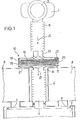
- a water collecting element 10 with the breathing tube connections 12 and 13 is interposed in the flow path of the breathing tube 6.
- the water collecting element 10 consists of a housing 18, 19, in which a storage material 16 which holds the water by capillary forces is arranged.
- the storage material 16 can advantageously be accommodated in an exchange cartridge 21 and the housing 18, 19 can be designed as an exchange system for the exchange cartridge 21.
- the housing 18, 19 of the water collecting element 10 can advantageously consist of two identical housing halves 18 and 19, which are held together by a closure element 20 to be actuated from the outside (FIG. 1).
- a closure element 20 to be actuated from the outside (FIG. 1).
- angular spacers 17 are arranged on the inside, which on the one hand encompass the replacement cartridge 21 in a positionally secure manner and on the other hand create the necessary distance for producing the air flow path, so that breathing air flows around the replacement cartridge 21 in the water collecting element 10 (FIG. 1) .
- the storage material 16 may preferably be granular and e.g. made of silica gel or alumina gel or a fibrous material and e.g. consist of glass wool or ceramic wool.
- FIG. 2 shows a further exemplary embodiment of a protective device according to the invention, namely that the replacement cartridge 21 receiving the storage material 16 is designed in a ring shape, so that the free center 22 is flowed through by the breathing air.
- the housing 18, 19 of the water collecting element 10 is in turn advantageously designed as a changing system and held together with the closure element.
- the two housing halves 18 and 19 are designed differently here.
- the upper housing half 18 uses a spacer ring 5 to ensure the position of the replacement cartridge 21 in the housing 18, 19 in the secure position there is a baffle 15 inside, which covers the central flow path for the breathing air.
- the baffle plate 15 is advantageously conical.
- the upper housing part 18 is adapted accordingly and is also conical in its shoulder region.
- the penetrating water either flows directly (FIG. 2) or via the baffle plate 15 (FIG. 1) into the water collecting element 10 and is safely collected by the storage material 16 of the replacement cartridge 21 . This ensures that no water can penetrate into the air flow path leading to the chemical canister 7 (arrow B).
- the capillary-active storage material 16 has the effect that the water once it has been absorbed is held in a position-independent manner and the respirator can be used in any position protected from water.
Landscapes
- Health & Medical Sciences (AREA)
- Pulmonology (AREA)
- General Health & Medical Sciences (AREA)
- Business, Economics & Management (AREA)
- Emergency Management (AREA)
- Chemical & Material Sciences (AREA)
- Chemical Kinetics & Catalysis (AREA)
- Emergency Medicine (AREA)
- General Chemical & Material Sciences (AREA)
- Respiratory Apparatuses And Protective Means (AREA)
Description
- Die Erfindung betrifft ein Wasserauffangelement für Atemschutzgeräte, insbesondere Unterwasseratemschutzgeräte nach dem Oberbegriff des Anspruchs 1, der von der DE-A-2 410 684 ausgeht.
- Bei einem Atemschutzgerät auf der Basis von Chemikal-Sauerstoff wird der für die Atmung erforderliche Sauerstoff aus einem Chemikal entwickelt, das den Sauerstoff bei ganz bestimmten Reaktionsbedingungen, wie z.B. durch den in der Ausatemluft befindlichen Wasserdampf und Kohlendioxid, abgibt. Hierbei beschleunigt maßgeblich die Feuchtigkeit die Erzeugung von Sauerstoff und es kann bei höherer Feuchtigkeit zu einer heftigen unkontrollierten exothermischen Reaktion mit einer Überproduktion von Sauerstoff kommen, so daß das sauerstoffabgebende Chemikal im Atemkanister in kurzer Zeit ganz oder teilweise verbraucht und damit der Einsatz des Atemschutzgerätes in Frage gestellt wird.
- Es ist bei Atemschutzgeräten mit Atemkanister bekannt, zwischen dem Mundstück des Atemschlauches und dem Atemkanister einen Speichelfang anzuordnen (DE-C-208 565) oder aber diesen Speichelfang am Boden eines den Atemkanister umgebenden Mantels vorzusehen (DE-B-1 246 414).
- Es ist weiterhin ein Atemschutzgerät bekannt, bei dem ein Wasserauffangelement im Strömungsweg des Atemschlauches angeordnet ist (DE-A-2 410 484). Hierdurch soll der Feuchtigkeitsgehalt der durch den Atemkanister strömenden Ausatemluft herabgesetzt werden.
- Die vorstehend genannten Atemschutzgeräte sind ausschließlich für den Einsatz Unter-oder Übertage geeignet. Bei Atemschutzgeräten mit Atemkanister, die Unterwasser eingesetzt werden sollen, liegt es auf der Hand, daß dem schädlichen Eindringen von Wasser in den Atemkanister ein Hauptaugenmerk geschenkt werden muß.
- Der Erfindung liegt deshalb die Aufgabe zugrunde, bei einem Unterwasser-Atemschutzgerät mit wasserempfindlichem Atemkanister ein Eindringen von Wasser in den Atemkanister beim Anlegen des Gerätes unter Wasser zu verhindern und ein Wasserauffangelement zu schaffen, das von der Atemluft nicht durchströmt wird.
- Diese Aufgabe wird erfindungsgemäß durch die im Kennzeichen des Patentanspruchs 1 zugegebenen Merkmale gelöst.
- Die mit der Erfindung erzielten Vorteile bestehen insbesondere darin, daß das Wasser, das beim Anlegen des Mundstücks unter Wasser in den Mund des Benutzers gelangt, durch den Atemschlauch in das Gerät gedrückt werden kann, ohne daß dadurch die Funktion des Gerätes beeinträchtigt wird. Darüberhinaus ist auch gewährleistet, daß das Atemschutzgerät in jeder Lage vor Wasser geschützt ist und weiter benutzt werden kann.
- Ausführungsbeispiele der Erfindung sind in der Zeichnung dargestellt und werden im folgenden näher beschrieben. Es zeigen:
- Fig. 1 eine schematische Darstellung der erfindungsgemäßen Schutzeinrichtung und
- Fig. 2 ein weiteres Ausführungsbeispiel der Schutzeinrichtung.
- An einem den Zugang von einem Mund-stück zum Atemschutzgerät 2 von Hand oder automatisch verschließenden Verschlußventil 3 ist ein Ende eines Atemschlauchs 6 befestigt, der mit seinem anderen Ende an einem Chemikalkanister 7 angeschlossen ist, dessen Austritt (in der Zeichnung nicht dargestellt) mit dem Atembeutel 8 in Verbindung steht (Fig. 2). Im Strömungsweg des Atemschlauchs 6 ist ein Wasserauffangelement 10 mit den Atemschlauchanschlüssen 12 und 13 zwischengeschaltet.
- Das Wasserauffangelement 10 besteht aus einem Gehäuse 18, 19, in das ein das Wasser durch Kapillarkräfte festhaltendes Speichermaterial 16 angeordnet ist. Das Speichermaterial 16 kann vorteilhaft in einer Auswechselpatrone 21 untergebracht und das Gehäuse 18, 19 als Wechselsystem für die Auswechselpatrone 21 ausgebildet sein.
- Das Gehäuse 18, 19 des Wasserauffangelementes 10 kann vorteilhaft aus zwei gleichen Gehäusehälften 18 und 19 bestehen, die durch ein von außen zu betätigendes Verschlußelement 20 zusammengehalten werden (Fig. 1). Am Umfang der Gehäusewand 18, 19 sind innen winkelförmige Distanzstücke 17 angeordnet, die einerseits die Auswechselpatrone 21 lagesicher umfassen und andererseits den erforderlichen Abstand zur Herstellung des Luftströmungsweges schaffen, so daß die Auswechselpatrone 21 im Wasserauffangelement 10 allseitig von Atemluft umströmt wird (Fig. 1).
- Das Speichermaterial 16 kann vorzugsweise gekörnt sein und z.B. aus Kieselgel oder Tonerdegel oder aber ein faserförmiges Material sein und z.B. aus Glaswatte oder aus Keramikwatte bestehen.
- In Fig. 2 ist ein weiteres Ausführungsbeispiel einer erfindungsgemäßen Schutzeinrichtung dargestellt, und zwar ist die das Speichermaterial 16 aufnehmende Auswechselpatrone 21 ringförmig ausgebildet, so daß das freie Zentrum 22 von der Atemluft durchströmt wird. Das Gehäuse 18, 19 des Wasserauffangelementes 10 ist vorteilhaft wiederum als Wechselsystem gestaltet und mit dem Verschlußelement zusammengehalten. Die beiden Gehäusehälften 18 und 19 sind hier jedoch verschieden ausgebildet. Die obere Gehäusehälfte 18 sorgt durch einen Distanzring 5 für die lagesichere Position der Auswechselpatrone 21 im Gehäuse 18, 19. Im Bereich der oberen Gehäusehälfte 18 befindet sich innen ein Prallblech 15, das den zentralen Strömungsweg für die Atemluft überdacht.
- Das Prallblech 15 ist vorteilhaft kegelförmig ausgebildet. Das Gehäuseoberteil 18 ist entsprechend angepaßt und in seinem Schulterbereich ebenfalls kegelförmig ausgebildet.
- Wie aus den Figuren 1 und 2 ersichtlich ist, fließt das eindringende Wasser (Pfeil A) entweder direkt (Fig. 2) oder über das Prallblech 15 (Fig. 1) in das Wasserauffangelement 10 und wird von dem Speichermaterial 16 der Auswechselpatrone 21 sicher aufgefangen. Damit ist gewährleistet, daß kein Wasser im zum Chemikalkanister 7 führenden Luftströmungsweg (Pfeil B) eindringen kann.
- Das kapillaraktive Speichermaterial 16 bewirkt, daß das einmal aufgenommene Wasser lageunabhängig festgehalten wird und das Atemschutzgerät in jeder Lage geschützt vor Wasser weiter benutzt werden kann.
Claims (4)
Priority Applications (1)
| Application Number | Priority Date | Filing Date | Title |
|---|---|---|---|
| AT79104565T ATE1736T1 (de) | 1978-11-20 | 1979-11-19 | Wasserauffangeinrichtung fuer atemschutzgeraete. |
Applications Claiming Priority (2)
| Application Number | Priority Date | Filing Date | Title |
|---|---|---|---|
| DE2850686 | 1978-11-20 | ||
| DE2850686A DE2850686C3 (de) | 1978-11-20 | 1978-11-20 | Schutzeinrichtung für Atemschutzgeräte |
Publications (2)
| Publication Number | Publication Date |
|---|---|
| EP0011306A1 EP0011306A1 (de) | 1980-05-28 |
| EP0011306B1 true EP0011306B1 (de) | 1982-11-03 |
Family
ID=6055360
Family Applications (1)
| Application Number | Title | Priority Date | Filing Date |
|---|---|---|---|
| EP79104565A Expired EP0011306B1 (de) | 1978-11-20 | 1979-11-19 | Wasserauffangeinrichtung für Atemschutzgeräte |
Country Status (3)
| Country | Link |
|---|---|
| EP (1) | EP0011306B1 (de) |
| AT (1) | ATE1736T1 (de) |
| DE (1) | DE2850686C3 (de) |
Families Citing this family (1)
| Publication number | Priority date | Publication date | Assignee | Title |
|---|---|---|---|---|
| GB2275612A (en) * | 1993-02-11 | 1994-09-07 | Coal Ind | Improvements in or relating to respiratory protective equipment |
Family Cites Families (6)
| Publication number | Priority date | Publication date | Assignee | Title |
|---|---|---|---|---|
| DE208565C (de) * | ||||
| DE385700C (de) * | 1921-08-20 | 1923-12-13 | Hanseatische Appbau Ges Vorm L | Geschlossenes Atmungsgeraet zum Aufenthalt in giftigen Gasen |
| GB271478A (de) * | 1926-05-20 | 1928-06-07 | Deutsche Gasgluhlicht Auer-Gesellschaft M.B.H. | |
| DE1246414B (de) * | 1966-03-29 | 1967-08-03 | Auergesellschaft Gmbh | Atemschutzgeraet mit Pendelatmung |
| DE2410684A1 (de) * | 1974-03-06 | 1975-09-25 | Vnii Gornospasatelnowo Dela | Isolierendes atemschutzgeraet |
| US4090511A (en) * | 1977-03-23 | 1978-05-23 | Mine Safety Appliances Company | Mouthpiece valve for escape breathing apparatus |
-
1978
- 1978-11-20 DE DE2850686A patent/DE2850686C3/de not_active Expired
-
1979
- 1979-11-19 AT AT79104565T patent/ATE1736T1/de not_active IP Right Cessation
- 1979-11-19 EP EP79104565A patent/EP0011306B1/de not_active Expired
Also Published As
| Publication number | Publication date |
|---|---|
| DE2850686A1 (de) | 1980-05-22 |
| DE2850686B2 (de) | 1980-10-02 |
| DE2850686C3 (de) | 1981-05-27 |
| ATE1736T1 (de) | 1982-11-15 |
| EP0011306A1 (de) | 1980-05-28 |
Similar Documents
| Publication | Publication Date | Title |
|---|---|---|
| EP1569710B1 (de) | Inhalationstherapievorrichtung | |
| EP0148325B1 (de) | Atemschutzgerät mit Schutzhaube | |
| DE2036024A1 (de) | Absorber | |
| DE2856349C3 (de) | Atemschutzgerät mit sauerstoffabgebender Chemikalpatrone | |
| DE2613852A1 (de) | Leichtes, unabhaengiges atmungsgeraet | |
| DE1709059B1 (de) | Ausatemventil fuer Atemschutzmasken | |
| DE1949038A1 (de) | Trennvorrichtung fuer Gase und Fluessigkeiten | |
| DE2852240A1 (de) | Luftreinigungspatrone fuer atemschutzgeraete | |
| DE3426757C2 (de) | ||
| DE3413906A1 (de) | Gehaeuse fuer gasfilterkanister | |
| DE3927594A1 (de) | Vorrichtung zum anwaermen und befeuchten von beatmungsgasen | |
| DE3329926A1 (de) | Befeuchtungsgeraet | |
| EP0011306A1 (de) | Wasserauffangeinrichtung für Atemschutzgeräte | |
| DE3426758C2 (de) | ||
| DE102005006012B3 (de) | Atemschutzgerät mit einer Sauerstoff erzeugenden Chemikalie zur Selbstrettung | |
| DE2726405C3 (de) | Atemschutzgerät mit Zweiwegatmung | |
| DE3426760C2 (de) | ||
| DE2923196C2 (de) | Sicherheitsabschluß für die Entlüftungsleitung von Kesselwagen | |
| DE2633431C3 (de) | Kohlendioxid-Absorber | |
| DE968520C (de) | Leicht zu oeffnender Behaelter zur wasserdampfdichten Aufnahme von Rettungs- und Atemschutzgeraeten | |
| DE2603531C2 (de) | Atemschutzgerät | |
| EP1064969B1 (de) | Sauerstoffbeatmungsgerät | |
| EP0081625B1 (de) | Atemschutzfilter | |
| AT110318B (de) | Trockenfeuerlöscher mit im Löschpulverbehälter gelagerter Druckgasflasche und Verteilerleitung. | |
| DE3027206C2 (de) | Isolierendes Atemschutzgerät |
Legal Events
| Date | Code | Title | Description |
|---|---|---|---|
| PUAI | Public reference made under article 153(3) epc to a published international application that has entered the european phase |
Free format text: ORIGINAL CODE: 0009012 |
|
| AK | Designated contracting states |
Designated state(s): AT BE FR GB IT NL SE |
|
| 17P | Request for examination filed | ||
| ITF | It: translation for a ep patent filed | ||
| GRAA | (expected) grant |
Free format text: ORIGINAL CODE: 0009210 |
|
| AK | Designated contracting states |
Designated state(s): AT BE FR GB IT NL SE |
|
| REF | Corresponds to: |
Ref document number: 1736 Country of ref document: AT Date of ref document: 19821115 Kind code of ref document: T |
|
| ET | Fr: translation filed | ||
| PGFP | Annual fee paid to national office [announced via postgrant information from national office to epo] |
Ref country code: FR Payment date: 19840920 Year of fee payment: 6 |
|
| PGFP | Annual fee paid to national office [announced via postgrant information from national office to epo] |
Ref country code: SE Payment date: 19840930 Year of fee payment: 6 Ref country code: BE Payment date: 19840930 Year of fee payment: 6 |
|
| PGFP | Annual fee paid to national office [announced via postgrant information from national office to epo] |
Ref country code: AT Payment date: 19851113 Year of fee payment: 7 |
|
| PGFP | Annual fee paid to national office [announced via postgrant information from national office to epo] |
Ref country code: NL Payment date: 19851130 Year of fee payment: 7 |
|
| PG25 | Lapsed in a contracting state [announced via postgrant information from national office to epo] |
Ref country code: AT Effective date: 19861119 |
|
| PG25 | Lapsed in a contracting state [announced via postgrant information from national office to epo] |
Ref country code: SE Effective date: 19861120 |
|
| PG25 | Lapsed in a contracting state [announced via postgrant information from national office to epo] |
Ref country code: BE Effective date: 19861130 |
|
| BERE | Be: lapsed |
Owner name: AUERGESELLSCHAFT G.M.B.H. Effective date: 19861130 |
|
| PG25 | Lapsed in a contracting state [announced via postgrant information from national office to epo] |
Ref country code: NL Effective date: 19870601 |
|
| NLV4 | Nl: lapsed or anulled due to non-payment of the annual fee | ||
| GBPC | Gb: european patent ceased through non-payment of renewal fee | ||
| PG25 | Lapsed in a contracting state [announced via postgrant information from national office to epo] |
Ref country code: FR Free format text: LAPSE BECAUSE OF NON-PAYMENT OF DUE FEES Effective date: 19870731 |
|
| REG | Reference to a national code |
Ref country code: FR Ref legal event code: ST |
|
| PG25 | Lapsed in a contracting state [announced via postgrant information from national office to epo] |
Ref country code: GB Effective date: 19881118 |
|
| EUG | Se: european patent has lapsed |
Ref document number: 79104565.1 Effective date: 19870812 |
|
| PLBE | No opposition filed within time limit |
Free format text: ORIGINAL CODE: 0009261 |
|
| STAA | Information on the status of an ep patent application or granted ep patent |
Free format text: STATUS: NO OPPOSITION FILED WITHIN TIME LIMIT |