EP0010796B1 - Eine aus einer elektrooptischen Flüssigkeitszelle bestehende Anzeigeanordnung - Google Patents
Eine aus einer elektrooptischen Flüssigkeitszelle bestehende Anzeigeanordnung Download PDFInfo
- Publication number
- EP0010796B1 EP0010796B1 EP19790200575 EP79200575A EP0010796B1 EP 0010796 B1 EP0010796 B1 EP 0010796B1 EP 19790200575 EP19790200575 EP 19790200575 EP 79200575 A EP79200575 A EP 79200575A EP 0010796 B1 EP0010796 B1 EP 0010796B1
- Authority
- EP
- European Patent Office
- Prior art keywords
- liquid cell
- liquid
- light
- light source
- diaphragm element
- Prior art date
- Legal status (The legal status is an assumption and is not a legal conclusion. Google has not performed a legal analysis and makes no representation as to the accuracy of the status listed.)
- Expired
Links
- 239000007788 liquid Substances 0.000 title claims description 29
- 230000000873 masking effect Effects 0.000 claims 3
- 238000009792 diffusion process Methods 0.000 claims 1
- 239000006059 cover glass Substances 0.000 description 5
- 230000007704 transition Effects 0.000 description 4
- 239000000853 adhesive Substances 0.000 description 2
- 230000001070 adhesive effect Effects 0.000 description 2
- 239000002313 adhesive film Substances 0.000 description 2
- 238000000149 argon plasma sintering Methods 0.000 description 2
- 230000007613 environmental effect Effects 0.000 description 2
- 230000003287 optical effect Effects 0.000 description 2
- 230000002349 favourable effect Effects 0.000 description 1
- 238000007654 immersion Methods 0.000 description 1
- 238000004519 manufacturing process Methods 0.000 description 1
- 239000000463 material Substances 0.000 description 1
- 230000005855 radiation Effects 0.000 description 1
- 238000002834 transmittance Methods 0.000 description 1
- 230000003313 weakening effect Effects 0.000 description 1
Images
Classifications
-
- G—PHYSICS
- G02—OPTICS
- G02F—OPTICAL DEVICES OR ARRANGEMENTS FOR THE CONTROL OF LIGHT BY MODIFICATION OF THE OPTICAL PROPERTIES OF THE MEDIA OF THE ELEMENTS INVOLVED THEREIN; NON-LINEAR OPTICS; FREQUENCY-CHANGING OF LIGHT; OPTICAL LOGIC ELEMENTS; OPTICAL ANALOGUE/DIGITAL CONVERTERS
- G02F1/00—Devices or arrangements for the control of the intensity, colour, phase, polarisation or direction of light arriving from an independent light source, e.g. switching, gating or modulating; Non-linear optics
- G02F1/01—Devices or arrangements for the control of the intensity, colour, phase, polarisation or direction of light arriving from an independent light source, e.g. switching, gating or modulating; Non-linear optics for the control of the intensity, phase, polarisation or colour
- G02F1/13—Devices or arrangements for the control of the intensity, colour, phase, polarisation or direction of light arriving from an independent light source, e.g. switching, gating or modulating; Non-linear optics for the control of the intensity, phase, polarisation or colour based on liquid crystals, e.g. single liquid crystal display cells
- G02F1/133—Constructional arrangements; Operation of liquid crystal cells; Circuit arrangements
- G02F1/1333—Constructional arrangements; Manufacturing methods
- G02F1/1335—Structural association of cells with optical devices, e.g. polarisers or reflectors
- G02F1/133502—Antiglare, refractive index matching layers
Definitions
- the invention relates to a display arrangement comprising a liquid cell in which the light scattering of a liquid layer lying between transparent electrodes can be switched by applying a voltage, in which a light source is provided behind the rear cover plate of the liquid cell and a diaphragm element is provided between the light source and liquid cell, which is in the direction of observation prevents the direct passage of light to the observer viewing the liquid cell from the front.
- DE-B-20 42 180 is a display arrangement of the type mentioned at the outset, with which usable results are achieved under suitable environmental lighting conditions and a suitable viewing angle.
- the disadvantage is that reflections of the illuminating light can occur at the media transitions, which reduce the contrast.
- immersion liquids or optical adhesives known per se in optics have proven to be a particularly suitable means of adapting this gap.
- the display arrangement is particularly simple to manufacture if the diaphragm element with the optical adhesive is designed as a self-adhesive film, which can be improved further in that this self-adhesive film is designed to be diffusely scattering on the side facing the light source.
- Residual reflections remaining at this gap between the liquid cell and the diaphragm element can be reduced by arranging a gray filter between the liquid of the liquid cell and the diaphragm element.
- this gray filter provides that it is applied directly to the rear wall of the liquid cell or to the diaphragm element or that the rear wall of the cell itself is designed as a gray filter. However, it is complex to adapt several media transitions completely without reflection.
- the object of the invention is to provide a display arrangement of the type mentioned at the outset which, under all normal ambient light conditions, for example also in sunlight and / or under a wide viewing angle, results in a legible display without disturbing shadows.
- the diaphragm element is arranged in the adjacent cover glass of the liquid cell, so that the light reaches the liquid from the rear of the diaphragm element without interfaces.
- the schematic arrangement according to the prior art shown in FIG. 1 consists of a liquid cell 10, a diaphragm element 7 and a light source 8. There is a gap 6 between the liquid cell 10 and the diaphragm element 7.
- the liquid cell 10 consists of the two cover glasses 1 and 5, which on their opposite sides 1a and 5a each carry transparent electrodes 2 and 4, between which there is a liquid 3 which changes its light transmittance when a voltage is applied between the electrodes 2 and 4.
- the electrodes 2 and 4 are generally divided into the desired shape of the character to be displayed, which is not shown in detail here.
- the diaphragm element 7 consists, for example, of many parallel lamellae which are embedded in a transparent film, such as “Venetian blind films” 8 from the company “3M Company •, and only lets light through in limited angular ranges. If the passage direction of the diaphragm element 7 is selected, for example, at approximately 45 degrees to the surface of the diaphragm element, then a viewer 12, who is viewing the diaphragm element 7 perpendicularly through the liquid cell 10, cannot see directly into the light source 8, but rather sees blackened slats of the diaphragm element 7 and with a transparent liquid, a black background. If parts of the electrodes 2 and 4 are now supplied with voltage in such a way that the transparency of the liquid 3 located between these parts is reduced and light scattering occurs, these areas appear to the viewer as bright spots on a dark background.
- a transparent film such as “Venetian blind films” 8 from the company “3M Company •
- the achievable contrast is achieved by light reflections on the front side facing the viewer 12 and on the gap 6 of the display arrangement limited.
- the cover glass 5 from FIG. 1 can be designed as a gray filter so that the reflection radiation occurring at the gap 6 due to imperfections in the index adjustment is reduced.
- FIG. 1 shows an arrangement according to the invention which corresponds in elements 1 to 4 to FIG. 1, the same elements then also bearing the same reference numerals.
- the refractive index adjustment takes place in that the diaphragm element 7 and the cover glass 5 of Fig. 1 are integrated into a single plate 9 by z. B. slats are formed in the material of this plate 9. Since no gap between cover glass 5 and aperture element 7 can occur due to this integrated structure, a complete refractive index adjustment takes place here, so that further measures are not necessary at this point and disturbing silhouettes because of the now vanishingly small distance between the liquid layer 3 and the in the plate 9 integrated aperture element does not occur.
Landscapes
- Physics & Mathematics (AREA)
- Nonlinear Science (AREA)
- Mathematical Physics (AREA)
- Chemical & Material Sciences (AREA)
- Crystallography & Structural Chemistry (AREA)
- General Physics & Mathematics (AREA)
- Optics & Photonics (AREA)
- Liquid Crystal (AREA)
- Devices For Indicating Variable Information By Combining Individual Elements (AREA)
- Mechanical Light Control Or Optical Switches (AREA)
- Electrochromic Elements, Electrophoresis, Or Variable Reflection Or Absorption Elements (AREA)
- Optical Elements Other Than Lenses (AREA)
Description
- Die Erfindung betrifft eine Anzeigeanordnung, bestehend aus einer Flüssigkeitszelle, bei der die lichtstreuung einer zwischen durchsichtigen Elektroden liegenden Flüssigkeitsschicht durch Anlegen einer Spannung schaltbar ist, bei der hinter der rückseitigen Deckplatte der Flüssigkeitszelle eine Lichtquelle und zwischen Lichtquelleiund Flüssigkeitszelle ein Blendenelement vorgesehen ist, welches in Beobachtungsrichtung den direkten Lichtdurchtritt zum die Flüssigkeitszelle von der Vorderseite betrachtenden Beobachter verhindert.
- Für Anzeigenanordnungen, die ohne mechanisch bewegliche Teile elektrisch geschaltet werden und die es gestatten, auch komplexere Figuren, wie alphanumerische Zeichen, bei flachen Abmessungen und bei geringem Leistungsbedarf unter normalen Umweltbedingungen darzustellen, entsteht mit der Zunahme der Elektronik in vielen Lebensbereichen ein steigender Bedarf.
- Bekannt ist aus der DE-B-20 42 180 eine Anzeigeanordnung der eingangs genannten Art, mit der unter geeigneten Umweltlichtverhältnissen und geeignetem Betrachtungswinkel brauchbare Ergebnisse erzielt werden.
- Nachteilig ist, daß an den Medienübergängen Reflexionen des beleuchtenden Lichtes auftreten können, welche kontrastmindernd wirken.
- Als günstig hat es sich deshalb erwiesen, die Vorderseite der Flüssigkeitszelle am Übergang auf Luft im Brechungsindex anzupassen.
- Vorteilhaft ist auch eine Brechungsindexanpassung zwischen der Flüssigkeitszelle und dem Blendenelement, da sich durch Lichtreflexionen an diesem Spalt neben der Schwächung des Kontrastes störende Schattenbilder der Anzeigeelemente ausbilden.
- Als besonders geeignetes Mittel zur Anpassung dieses Spaltes haben sich beispielsweise die in der Optik an sich bekannten Immersionsflüssigkeiten oder optische Klebstoffe erwiesen.
- Besonders einfach herzustellen ist die Anzeigeanordnung, wenn das Blendenelement mit dem optischen Klebstoff als Selbstklebefolie ausgebildet ist, was sich noch dahingehend verbessern läßt, daß diese Selbstklebefolie auf der zur Lichtquelle gewandten Seite diffus streuend gestaltet ist.
- Verbleibende Restreflexionen an diesem Spalt zwischen Flüssigkeitszelle und Blendenelement können durch Anordnen eines Graufilters zwischen der Flüssigkeit der Flüssigkeitszelle und dem Blendenelement vermindert werden.
- Günstige Ausgestaltungen dieses Graufilters sehen vor, daß dieses direkt auf die Rückwand der Flüssigkeitszelle oder auf das Blendenelement aufgebracht oder die Rückwand der Zelle selbst als Graufilter ausgeführt wird. Es ist jedoch aufwendig, mehrere Medienübergänge vollständig reflexionsfrei anzupassen.
- Aufgabe der Erfindung ist es, eine Anzeigeanordnung der eingangs genannten Art anzugeben, die unter allen normalen Umweltlichtverhältnissen, beispielsweise auch bei Sonneneinstrahlung und/oder unter einem weiten Betrachtungswinkel eine gut lesbare Anzeige ohne störende Schattenbilder ergeben.
- Gelöst wird diese Aufgabe gemäß dem Kennzeichen des Anspruches. Zur Verminderung von Reflexionen wird die Anzahl der Medienübergänge verkleinert.
- Es erfolgt eine nahezu vollständige Vermeidung von Reflexionen, wenn man erfindungsgemäß das Blendelement im angrenzenden Deckglas der Flüssigkeitszelle anordnet, so daß das Licht von der Rückseite des Blendenelementes ohne Grenzflächen bis zur Flüssigkeit gelangt.
- Die Erfindung soll nun an einem Ausführungsbeispiel näher erläutert werden. Es zeigen :
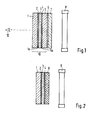
- Figur 1 den schematischen Aufbau einer Anzeigeanordnung nach dem Stand der Technik und
- Figur 2 eine erfindungsgemäße Anzeigeanordnung mit integrierter Deckplatte.
- Die in Fig. 1 gezeigte schematisierte Anordnung nach dem Stand der Technik besteht aus einer Flüssigkeitszelle 10, einem Blendenelement 7 und einer Lichtquelle 8. Zwischen der Flüssigkeitszelle 10 und dem Blendenelement 7 befindet sich ein Spalt 6. Die Flüssigkeitszelle 10 besteht aus den beiden Deckgläsern 1 und 5, die auf ihren gegenüberliegenden Seiten 1a und 5a jeweils transparente Elektroden 2 und 4 tragen, zwischen denen sich eine Flüssigkeit 3 befindet, die bei Anlegen einer Spannung zwischen die Elektroden 2 und 4 ihre Lichtdurchlässigkeit verändert. Die Elektroden 2 und 4 sind im allgemeinen in der gewünschten Form des darzustellenden Zeichens unterteilt, was hier nicht im einzelnen gezeigt ist.
- Das Blendenelement 7 besteht beispielsweise aus vielen parallelen Lamellen, die in eine durchsichtige Folie eingebettet sind, wie beispielsweise « Jalousienfolien »8 der Firma « 3M Company •, und Läßt Licht nur in begrenzten Winkelbereichen hindurch. Wird die Durchlassrichtung des Blendenelements 7 beispielsweise mit etwa 45 Grad zur Fläche des Blendenelementes gewählt, so kann ein Betrachter 12, der senkrecht durch die Flüssigkeitszelle 10 das Blendenelement 7 betrachtet, nicht direkt in die Lichtquelle 8 sehen, sondern sieht bei geschwärzten Lamellen des Blendenelementes 7 und bei transparenter Flüssigkeit einen schwarzen Hintergrund. Werden nun Teile der Elektroden 2 und 4 so mit Spannung versorgt, daß die Transparenz der zwischen diesen Teilen befindlichen Flüssigkeit 3 sich verringert und Lichtstreuung eintritt, so erscheinen diese Bereiche für den Betrachter als helle Stellen auf dunklem Hintergrund.
- Durch Lichtreflexionen an der dem Betrachter 12 zugewandten Vorderseite und am Spalt 6 der Anzeigeanordnung wird der erzielbare Kontrast begrenzt.
- Das Deckglas 5 aus Fig. 1 kann als Graufilter ausgebildet sein, damit die durch Unvollkommenheiten der Indexanpassung am Spalt 6 auftretende Reflexionsstrahlung verringert wird.
- Fig. zeigt eine Anordnung gemäß der Erfindung, die in den Elementen 1 bis 4 mit der Fig. 1 übereinstimmt, wobei gleiche Elemente dann auch das gleiche Bezugszeichen tragen. In Fig. 2 erfolgt die Brechungsindexanpassung dadurch, daß das Blendenelement 7 und das Deckglas 5 der Fig. 1 zu einer einzigen Platte 9 integriert werden, indem z. B. Lamellen im Material dieser Platte 9 ausgebildet sind. Da durch diesen integrierten Aufbau auch kein Spalt zwischen Deckglas 5 und Blendenelement 7 mehr auftreten kann, erfolgt hier eine vollständige Brechungsindexanpassung, so daß an dieser Stelle weitere Maßnahmen nicht notwendig sind und störende Schattenbilder wegen des nunmehr verschwindend kleinen Abstandes zwischen der Flüssigkeitsschicht 3 und dem in der Platte 9 integrierten Blendenelement nicht auftreten.
Claims (1)
- Anzeigeanordnung, bestehend aus einer Flüssigkeitszelle, bei der die Lichtstreuung einer zwischen durchsichtigen Elektroden Liegenden Flüssigkeitsschicht durch Anlegen einer Spannung schaltbar ist, bei der hinter der rückseitigen Deckplatte der Flüssigkeitszelle eine Lichtquelle und zwischen Lichtquelle und Flüssigkeitszelle ein Blendenelement vorgesehen ist, welches in Beobachtungsrichtung den direkten Lichtdurchtritt zum die Flüssigkeitszelle von der Vorderseite betrachtenden Beobachter verhindert, dadurch gekennzeichnet, daß das Blendenelement und die der Lichtquelle (8) zugewande rückseitige Deckplatte der Flüssigkeitszelle (10) zu einer einzigen Platte als Rückwand (9) integriert sind.
Applications Claiming Priority (2)
| Application Number | Priority Date | Filing Date | Title |
|---|---|---|---|
| DE2845858 | 1978-10-21 | ||
| DE19782845858 DE2845858C2 (de) | 1978-10-21 | 1978-10-21 | Anzeigeanordnung |
Publications (2)
| Publication Number | Publication Date |
|---|---|
| EP0010796A1 EP0010796A1 (de) | 1980-05-14 |
| EP0010796B1 true EP0010796B1 (de) | 1983-10-05 |
Family
ID=6052739
Family Applications (1)
| Application Number | Title | Priority Date | Filing Date |
|---|---|---|---|
| EP19790200575 Expired EP0010796B1 (de) | 1978-10-21 | 1979-10-09 | Eine aus einer elektrooptischen Flüssigkeitszelle bestehende Anzeigeanordnung |
Country Status (4)
| Country | Link |
|---|---|
| EP (1) | EP0010796B1 (de) |
| JP (1) | JPS55105281A (de) |
| DD (1) | DD146666A5 (de) |
| DE (1) | DE2845858C2 (de) |
Families Citing this family (12)
| Publication number | Priority date | Publication date | Assignee | Title |
|---|---|---|---|---|
| DE2937054A1 (de) * | 1979-09-13 | 1981-03-19 | Standard Elektrik Lorenz Ag, 7000 Stuttgart | Anzeigeanordnung mit einer fluessigkeitszelle |
| DE2937975A1 (de) * | 1979-09-20 | 1981-04-02 | Licentia Patent-Verwaltungs-Gmbh, 6000 Frankfurt | Blendenanordnung |
| US4606611A (en) * | 1981-09-16 | 1986-08-19 | Manchester R & D Partnership | Enhanced scattering in voltage sensitive encapsulated liquid crystal |
| US5082351A (en) * | 1981-09-16 | 1992-01-21 | Manchester R & D Partnership | Encapsulated liquid crystal material, apparatus and method |
| US5089904A (en) * | 1981-09-16 | 1992-02-18 | Fergason James L | Encapsulated liquid crystal material, apparatus and method |
| US4810063A (en) * | 1981-09-16 | 1989-03-07 | Manchester R & D Partnership | Enhanced scattering voltage sensitive encapsulated liquid crystal with light directing and interference layer features |
| EP0260455B1 (de) * | 1983-03-21 | 1995-01-11 | MANCHESTER R & D LIMITED PARTNERSHIP | Erhöhung der Streuung bei spannungsempfindlichen eingekapselten Flüssigkristallen |
| US4591233A (en) * | 1983-03-21 | 1986-05-27 | Manchester R & D Partnership | Enhanced scattering in voltage sensitive encapsulated liquid crystal with spaced apart absorber |
| FR2672135A1 (fr) * | 1991-01-25 | 1992-07-31 | Asulab Sa | Dispositif optique a transmittance variable notamment pour retroviseur. |
| US5177629A (en) * | 1991-06-13 | 1993-01-05 | Proxima Corporation | Liquid crystal display with an optical fluid layer |
| US7167309B2 (en) * | 2004-06-25 | 2007-01-23 | Northrop Grumman Corporation | Optical compensation of cover glass-air gap-display stack for high ambient lighting |
| DE102012224352A1 (de) | 2012-12-21 | 2014-06-26 | Continental Automotive Gmbh | Elektrooptische Anzeige mit einer transparenten Abdeckung |
Family Cites Families (9)
| Publication number | Priority date | Publication date | Assignee | Title |
|---|---|---|---|---|
| BE755222A (fr) * | 1969-08-25 | 1971-02-01 | Rca Corp | Dispositif a cristal liquide |
| DE2237084A1 (de) * | 1972-07-28 | 1974-02-14 | Battelle Institut E V | Messgeraet fuer elektrische spannungen |
| US3971869A (en) * | 1973-03-05 | 1976-07-27 | Optical Coating Laboratory, Inc. | Liquid crystal display device and method |
| US3811751A (en) * | 1973-04-02 | 1974-05-21 | Hughes Aircraft Co | Self-illuminated liquid crystal display panel |
| US3838909A (en) * | 1973-04-06 | 1974-10-01 | Rockwell International Corp | Ambient illuminations system for liquid crystal display |
| CA1041643A (en) * | 1974-05-10 | 1978-10-31 | Xerox Corporation | Imaging system |
| CH601823A5 (en) * | 1975-08-14 | 1978-07-14 | Bbc Brown Boveri & Cie | Liquid crystal indicating unit with protective glass |
| CH613597B (de) * | 1975-08-14 | Bbc Brown Boveri & Cie | Hinter einem frontglas eines zeitmessgeraetes angeordnete fluessigkristallanzeige. | |
| US4042294A (en) * | 1976-03-17 | 1977-08-16 | Micro Display Systems Inc | Illuminated electro-optical display apparatus |
-
1978
- 1978-10-21 DE DE19782845858 patent/DE2845858C2/de not_active Expired
-
1979
- 1979-10-09 EP EP19790200575 patent/EP0010796B1/de not_active Expired
- 1979-10-18 DD DD21631479A patent/DD146666A5/de unknown
- 1979-10-22 JP JP13628179A patent/JPS55105281A/ja active Pending
Also Published As
| Publication number | Publication date |
|---|---|
| JPS55105281A (en) | 1980-08-12 |
| EP0010796A1 (de) | 1980-05-14 |
| DE2845858A1 (de) | 1980-04-24 |
| DE2845858C2 (de) | 1981-10-08 |
| DD146666A5 (de) | 1981-02-18 |
Similar Documents
| Publication | Publication Date | Title |
|---|---|---|
| DE2422417C3 (de) | Beleuchtungsvorrichtung für Mikroskope | |
| EP0010796B1 (de) | Eine aus einer elektrooptischen Flüssigkeitszelle bestehende Anzeigeanordnung | |
| DE69317184T2 (de) | Hinterbeleuchtungsvorrichtung für eine Flüssigkristall-Anzeigevorrichtung | |
| DE69019712T2 (de) | Augenschutzbrille mit Flüssigkristall-Lichtventil. | |
| EP0097384A1 (de) | Flüssigkristallanzeigevorrichtung | |
| DE2627934C2 (de) | Beleuchtete Anzeigevorrichtung, insbesondere für Verkehrssignale | |
| DE3120601A1 (de) | Anordnung zur wiedergabe von informationen | |
| DE69215171T2 (de) | Flüssigkristallanzeigevorrichtung | |
| DE2042180A1 (de) | Anzeigevorrichtung mit einer Fluessig-Kristall-Zelle | |
| DE4244448C2 (de) | Verfahren und Anordnung zur optischen Darstellung von Informationen | |
| DE3032344A1 (de) | Fluessigkeitskristallanzeigen | |
| AT390851B (de) | Einrichtung zur darbietung von informationen, anzeigen, hinweisen etc. | |
| DE2931328A1 (de) | Anzeigeanordnung | |
| DE2358415A1 (de) | Fluessigkristallbauelement nach dem reflexionsprinzip | |
| DE2640909C2 (de) | Anzeigevorrichtung mit einem Strahlungskollektor und -verdichter | |
| DE2735194C3 (de) | Anordnung zur Darstellung von Betriebsdaten eines Fahrzeuges | |
| EP1696260A2 (de) | Flüssigkristallanzeigeeinrichtung sowie Flüssigkristallanzeigeanordnung mit einer Mehrzahl von solchen Flüssigkristallanzeigeeinrichtungen | |
| DE2706372B2 (de) | Anzeigeanordnung zur Darstellung von hellen Bildern auf dunklem Hintergrund | |
| DE934313C (de) | Anordnung zur Verstaerkung der Lichtintensitaet eines optisch projizierten Bildes | |
| DE102019109365A1 (de) | Photochromfilm | |
| DE3403713C2 (de) | ||
| DE19520822C1 (de) | Linien-, Ziel- oder Haltestellenanzeige | |
| DE3644525A1 (de) | Sichtanzeige | |
| DE2620015A1 (de) | Vorrichtung zur steuerung eines lichtstrahlenbuendels | |
| DD211191A1 (de) | Anordnung von anzeigeindikatoren fuer spiegelreflexkameras |
Legal Events
| Date | Code | Title | Description |
|---|---|---|---|
| PUAI | Public reference made under article 153(3) epc to a published international application that has entered the european phase |
Free format text: ORIGINAL CODE: 0009012 |
|
| AK | Designated contracting states |
Designated state(s): BE CH FR IT NL |
|
| 17P | Request for examination filed |
Effective date: 19801108 |
|
| ITF | It: translation for a ep patent filed | ||
| GRAA | (expected) grant |
Free format text: ORIGINAL CODE: 0009210 |
|
| AK | Designated contracting states |
Designated state(s): BE CH FR IT NL |
|
| PGFP | Annual fee paid to national office [announced via postgrant information from national office to epo] |
Ref country code: NL Payment date: 19831026 Year of fee payment: 5 |
|
| PGFP | Annual fee paid to national office [announced via postgrant information from national office to epo] |
Ref country code: FR Payment date: 19831125 Year of fee payment: 5 |
|
| ET | Fr: translation filed | ||
| PGFP | Annual fee paid to national office [announced via postgrant information from national office to epo] |
Ref country code: CH Payment date: 19840117 Year of fee payment: 5 |
|
| PGFP | Annual fee paid to national office [announced via postgrant information from national office to epo] |
Ref country code: BE Payment date: 19840331 Year of fee payment: 5 |
|
| PLBE | No opposition filed within time limit |
Free format text: ORIGINAL CODE: 0009261 |
|
| STAA | Information on the status of an ep patent application or granted ep patent |
Free format text: STATUS: NO OPPOSITION FILED WITHIN TIME LIMIT |
|
| 26N | No opposition filed | ||
| PG25 | Lapsed in a contracting state [announced via postgrant information from national office to epo] |
Ref country code: CH Effective date: 19841031 Ref country code: BE Effective date: 19841031 |
|
| BERE | Be: lapsed |
Owner name: INTERNATIONAL STANDARD ELECTRIC CORP. Effective date: 19841009 |
|
| PG25 | Lapsed in a contracting state [announced via postgrant information from national office to epo] |
Ref country code: NL Effective date: 19850501 |
|
| NLV4 | Nl: lapsed or anulled due to non-payment of the annual fee | ||
| PG25 | Lapsed in a contracting state [announced via postgrant information from national office to epo] |
Ref country code: FR Free format text: LAPSE BECAUSE OF NON-PAYMENT OF DUE FEES Effective date: 19850628 |
|
| REG | Reference to a national code |
Ref country code: CH Ref legal event code: PL |
|
| REG | Reference to a national code |
Ref country code: FR Ref legal event code: ST |