EP0006823A2 - Lastkahn für eine Vorrichtung zur Bergung von auf dem Wasser schwimmenden Materialien - Google Patents
Lastkahn für eine Vorrichtung zur Bergung von auf dem Wasser schwimmenden Materialien Download PDFInfo
- Publication number
- EP0006823A2 EP0006823A2 EP79400451A EP79400451A EP0006823A2 EP 0006823 A2 EP0006823 A2 EP 0006823A2 EP 79400451 A EP79400451 A EP 79400451A EP 79400451 A EP79400451 A EP 79400451A EP 0006823 A2 EP0006823 A2 EP 0006823A2
- Authority
- EP
- European Patent Office
- Prior art keywords
- tank
- barge
- water
- floating
- mouth
- Prior art date
- Legal status (The legal status is an assumption and is not a legal conclusion. Google has not performed a legal analysis and makes no representation as to the accuracy of the status listed.)
- Granted
Links
Images


Classifications
-
- E—FIXED CONSTRUCTIONS
- E02—HYDRAULIC ENGINEERING; FOUNDATIONS; SOIL SHIFTING
- E02B—HYDRAULIC ENGINEERING
- E02B15/00—Cleaning or keeping clear the surface of open water; Apparatus therefor
- E02B15/04—Devices for cleaning or keeping clear the surface of open water from oil or like floating materials by separating or removing these materials
- E02B15/10—Devices for removing the material from the surface
- E02B15/104—Conveyors; Paddle wheels; Endless belts
-
- E—FIXED CONSTRUCTIONS
- E02—HYDRAULIC ENGINEERING; FOUNDATIONS; SOIL SHIFTING
- E02B—HYDRAULIC ENGINEERING
- E02B15/00—Cleaning or keeping clear the surface of open water; Apparatus therefor
- E02B15/04—Devices for cleaning or keeping clear the surface of open water from oil or like floating materials by separating or removing these materials
- E02B15/046—Collection of oil using vessels, i.e. boats, barges
-
- B—PERFORMING OPERATIONS; TRANSPORTING
- B63—SHIPS OR OTHER WATERBORNE VESSELS; RELATED EQUIPMENT
- B63B—SHIPS OR OTHER WATERBORNE VESSELS; EQUIPMENT FOR SHIPPING
- B63B35/00—Vessels or similar floating structures specially adapted for specific purposes and not otherwise provided for
- B63B35/32—Vessels or similar floating structures specially adapted for specific purposes and not otherwise provided for for collecting pollution from open water
-
- Y—GENERAL TAGGING OF NEW TECHNOLOGICAL DEVELOPMENTS; GENERAL TAGGING OF CROSS-SECTIONAL TECHNOLOGIES SPANNING OVER SEVERAL SECTIONS OF THE IPC; TECHNICAL SUBJECTS COVERED BY FORMER USPC CROSS-REFERENCE ART COLLECTIONS [XRACs] AND DIGESTS
- Y10—TECHNICAL SUBJECTS COVERED BY FORMER USPC
- Y10S—TECHNICAL SUBJECTS COVERED BY FORMER USPC CROSS-REFERENCE ART COLLECTIONS [XRACs] AND DIGESTS
- Y10S210/00—Liquid purification or separation
- Y10S210/918—Miscellaneous specific techniques
- Y10S210/922—Oil spill cleanup, e.g. bacterial
- Y10S210/923—Oil spill cleanup, e.g. bacterial using mechanical means, e.g. skimmers, pump
Definitions
- the invention relates to barges on which are mounted floating pollution control devices.
- suction, noria, vane pump, etc. All have a slightly submerged mouth which is followed by an elevator bringing the collected materials to a discharge chute from where they are discharged into a settling and storage tank.
- the first object is achieved according to the invention by a device consisting of two long blades articulated respectively on either side of the mouth of the recovery device, on the walls of the mouth itself or on the barge, around a fixed point or at least three orthogonal axes; each of said blades carrying at an appropriate distance from this articulation an operating arm directed upwards and forming with the blade an obtuse angle, so that it can be grasped, by its end forming a handle, by an operator on board the barge.
- the operator can thus print opposite "scull" movements on the blades to create a current tending to bring the floating layer towards the mouth of the recovery device.
- the pressurized water can come, for example, from a pump taking water from the environment where the barge floats.
- the second goal, stabilization of the immersion depth of the mouth, is achieved by taking as a settling tank a so-called submerged tank at substantially constant level.
- This initial level being variable, as it is said above since it depends on the draft to be respected, it is necessary to adjust the level of the evacuation orifice of the overflow pipe; this adjustment can be carried out by constituting the ascending part of said pipe by telescopic elements or even by providing a flexible pipe over at least part of its length.
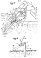
- a barge 1 carries an apparatus 2 for recovering floating materials and a tank 3 for settling and storage for said materials which are poured therein by the elevator of the apparatus 2.
- the barge is provided with two blades 4a, 4b articulated respectively on either side of the mouth 2 a on the hull of the barge or on the recovery device 2 as is the case in the example shown.
- the articulation of each of the blades can be carried out around a fixed point (ball joint), but certain rotations must be limited by stops and it is then preferable to provide, as shown (figure 2), an articulation around three orthogonal axes 5, 10 and 11, one of which, 5, is substantially vertical.
- Axis 5 is the scanning axis
- axis 10 is the lifting axis
- axis 11 is the tilting axis.
- each blade carries an operating arm 9 directed obliquely upwards so that its end 9a forming a handle can be grasped by an operator on board the barge.
- the blades 4 a and 4 b being separated from one another as re shown in solid lines in FIG. 1 (position I) and each blade having its cross section vertically (position I in FIG. 3), makes them pivot towards one another according to the arrows f 1 , around the axes 5, by acting on the arms 9 until their free ends meet in the median plane of the barge in position III, after having passed through the intermediate position II.
- This sweeping movement of the surface of the body of water tends to bring the floating materials in the axis of the barge.
- each blade can carry a nozzle 8, like the blade 4 in FIG. A 1, or a plurality of nozzles 8, like the blade 4 b . All the nozzles are supplied by a flexible pipe with pressurized water, thanks to a pump drawing the water on which the barge floats.
- Each blade carries at its free end, on the face facing outwards, a float 16 (FIG. 2) which "follows" the surface movements of the water body (the blade playing around the axis 10) and in at the same time creates a torque which, in FIG. 2, tends to rotate the blade 4a around the axis 11 in the direct direction, thus applying the blade against a stop 17 in the vertical position shown in FIGS. 2 and 3.
- a float 16 FIG. 2
- the efficiency of the device 2 also depends on the depth of immersion of the mouthpiece 2.
- the optimum immersion depth is known, it is important to adjust the position of the device accordingly and to avoid variations in the draft of the barge to keep this immersion substantially constant.
- FIG. 1 there is a barge 1 carrying an apparatus 2 for recovering floating materials and a tank 3 for settling and storage.
- a tank 3 for settling and storage.
- the motor 20 for propelling the barge.
- the floating materials collected by the mouth 2 a of the device 2 are transported by the elevator of said device and then poured into the tank 3, here by means of a chute 21.
- the tank 3 is a so-called submerged tank, that is to say filled with water at the start of work and this water is evacuated as the water + floating materials mixture from the device 2 is poured out.
- the tank 3 can be described as a submerged tank at constant level when this compensation is obtained, but this is not perfectly exact.
- the adjustment of the water drainage can be done manually ment, for example using a flywheel 22 actuating a flat shutter 23 disposed at the bottom of the tank on an outlet orifice 24.
- the barge is in the empty navigation position, the draft h is weak and the tank 3 contains little water whose entry is possibly due to an imperfect seal of the shutter 23 (maximum height of the water in the tank: h).
- the tank is filled with water until the suitable draft H is obtained and the immersion of the mouth 2a of the recovery device is adjusted.
- the shutter 23 is always closed.
- FIG. 6C the work of recovery of the floating materials 26 is started.
- the shutter 23 is open so as to partially release the orifice 24 so that the water from the tank flows with a flow rate corresponding to that of the arrival of the water + materials mixture.
- the opening is adjusted by trial and error and must be corrected intermittently to maintain the H value of the draft.
- the tank 3 is substantially filled with the materials recovered.
- the operator is informed of this by means of a dip tube 25, the upper end of which exceeds the maximum filling level of the tank and the lower end of which opens out near the bottom of the tank.
- the recovered materials reach the level of the lower end of the tube, it passes through the latter and we see them appear on the surface at 27 and the operator then closes the shutter 23.
- an automatic compensation can be provided by means of an overflow tube 28, as shown in FIG. 7, plunging to the vicinity of the bottom of the tank 3 and bent at right angles to its upper part to lead to one of the lateral sides of the barge.
- An exact weight compensation is thus obtained at all times between the water discharged through the orifice 29 a of the overflow and the recovered materials 26 poured into the tank.
- This compensation being made by weight, the level reached in the tank by the materials 26 is slight ment higher than the level of water in the overflow tube, this last level being the initial level of water in the tank before the start of the recovery work.
- this initial water level depends on the draft H to be respected and it can therefore vary although in fairly small proportions.
- the bent part 29 of the overflow is fitted telescopically and with gentle friction on the vertical part 28 and a link 30 or any other means of retaining or blocking makes it possible to maintain it in the chosen position.
- a flexible part can be provided, which also makes it possible to vary the level of the discharge orifice.
Landscapes
- Engineering & Computer Science (AREA)
- General Engineering & Computer Science (AREA)
- Environmental & Geological Engineering (AREA)
- Mechanical Engineering (AREA)
- Civil Engineering (AREA)
- Structural Engineering (AREA)
- Cleaning Or Clearing Of The Surface Of Open Water (AREA)
- Ship Loading And Unloading (AREA)
- Harvesting Machines For Specific Crops (AREA)
Applications Claiming Priority (2)
| Application Number | Priority Date | Filing Date | Title |
|---|---|---|---|
| FR7819943 | 1978-07-04 | ||
| FR7819943A FR2430350B1 (de) | 1978-07-04 | 1978-07-04 |
Publications (3)
| Publication Number | Publication Date |
|---|---|
| EP0006823A2 true EP0006823A2 (de) | 1980-01-09 |
| EP0006823A3 EP0006823A3 (en) | 1980-01-23 |
| EP0006823B1 EP0006823B1 (de) | 1981-10-07 |
Family
ID=9210321
Family Applications (1)
| Application Number | Title | Priority Date | Filing Date |
|---|---|---|---|
| EP79400451A Expired EP0006823B1 (de) | 1978-07-04 | 1979-07-03 | Lastkahn für eine Vorrichtung zur Bergung von auf dem Wasser schwimmenden Materialien |
Country Status (5)
| Country | Link |
|---|---|
| US (1) | US4264444A (de) |
| EP (1) | EP0006823B1 (de) |
| DE (1) | DE2960934D1 (de) |
| ES (1) | ES482195A1 (de) |
| FR (1) | FR2430350B1 (de) |
Cited By (6)
| Publication number | Priority date | Publication date | Assignee | Title |
|---|---|---|---|---|
| FR2684065A1 (fr) * | 1991-11-26 | 1993-05-28 | Morillon Corvol Courbot | Bateau recuperateur d'objets flottants. |
| FR2686567A1 (fr) * | 1992-01-28 | 1993-07-30 | Carpentier Henry | Collecteur de surface antipollution marine. |
| FR2694737A1 (fr) * | 1992-08-11 | 1994-02-18 | Eaux Cie Gle | Navire dépollueur. |
| FR2698337A1 (fr) * | 1992-11-24 | 1994-05-27 | Eaux Cie Gle | Scooter de mer pour la récupération des polluants flottants. |
| FR2719610A1 (fr) * | 1994-05-06 | 1995-11-10 | Bronnec Jean Armand Louis | Dispositif de récupération de produits polluants répandus sur l'eau ou sur le sol. |
| CN109137864A (zh) * | 2018-09-26 | 2019-01-04 | 周楠 | 一种河道生态修复用河面浮萍打捞收集装置 |
Families Citing this family (42)
| Publication number | Priority date | Publication date | Assignee | Title |
|---|---|---|---|---|
| IT8347828A0 (it) * | 1983-03-01 | 1983-03-01 | Ayroldi Giuseppe | Battello multiuso per la raccoltadi oli galleggianti |
| CA1225288A (en) * | 1985-12-17 | 1987-08-11 | Christopher Ives | Linear propeller |
| US4707253A (en) * | 1986-09-22 | 1987-11-17 | Ray Rowe | Swimming pool skimmer accelerator |
| US4904379A (en) * | 1987-08-18 | 1990-02-27 | Ward John F | Skimmer-diverter assembly for removing debris from swimming pools and the like |
| US4842735A (en) * | 1988-03-21 | 1989-06-27 | Hollis Calvin L | Oil skimming apparatus |
| US5028325A (en) * | 1990-01-04 | 1991-07-02 | Hamilton William R | Water rake |
| US5045216A (en) * | 1990-02-27 | 1991-09-03 | Eller J David | Method, system and collecting vessel for oil spill recovery |
| US5183579A (en) * | 1990-02-27 | 1993-02-02 | Eller J David | Method, system and apparatus for handling substances on or in water |
| NO910920L (no) * | 1991-03-08 | 1992-09-09 | Odd Pettersen | Fremgangsmaate og anordning til oppsamling av oljeforurensning paa en vannflate. |
| US5194151A (en) * | 1991-10-15 | 1993-03-16 | Broussard David G | Oil skimmer |
| US6115954A (en) * | 1995-12-07 | 2000-09-12 | Willener; John A. | Collection assemblies and methods for use in harvesting brine shrimp eggs |
| US5890311A (en) * | 1995-12-07 | 1999-04-06 | Willener; John A. | Apparatus and methods for harvesting and cleaning brine shrimp eggs |
| US6073382A (en) * | 1995-12-07 | 2000-06-13 | Willener; John A. | Containment boom apparatus and methods for use in harvesting brine shrimp eggs |
| US5863440A (en) * | 1996-05-24 | 1999-01-26 | Abtech Industries, Inc. | Methods for ameliorating oil spills in marine and inland waters |
| DE69827937T2 (de) | 1997-01-10 | 2005-12-22 | Abtech Industries, Inc., Scottsdale | Systeme zur verbesserten behandlung von kohlenwasserstoffverunreinigungen in wässrigem milieu |
| US6541569B1 (en) | 1997-01-10 | 2003-04-01 | Abtech Industries, Inc. | Polymer alloys, morphology and materials for environmental remediation |
| US5738036A (en) * | 1997-04-30 | 1998-04-14 | Jones; Nathan | Platform and supporting structures for a boat |
| US6099723A (en) * | 1997-06-06 | 2000-08-08 | Abtech Industries, Inc. | Catchbasin systems for filtering hydrocarbon spills |
| WO1999042405A1 (en) | 1998-02-18 | 1999-08-26 | Abtech Industries, Inc. | Curb-inlet storm drain systems for filtering trash and hydrocarbons |
| US6080307A (en) * | 1998-09-29 | 2000-06-27 | Abtech Industries, Inc. | Storm drain systems for filtering trash and hydrocarbons |
| US6531059B1 (en) | 2000-10-05 | 2003-03-11 | Abtech Industries, Inc. | Suspended runoff water filter |
| GB0110381D0 (en) * | 2001-04-27 | 2001-06-20 | Fisk Clive S M | Oil slick harvesting |
| WO2004003300A1 (en) * | 2002-07-01 | 2004-01-08 | Clive Stephen Montague Fisk | Oil slick harvester |
| NO20041471A (no) * | 2004-04-07 | 2005-08-15 | Ide Til Produkt As | Fremgangsmåte og anordning for oppsamling av flytende avfall på en vannoverflate. |
| NL1029936C2 (nl) * | 2005-09-13 | 2007-03-15 | Koseq B V | Systeem voor het van een wateroppervlak verwijderen van olie. |
| US20090057217A1 (en) * | 2007-09-05 | 2009-03-05 | Seawax International, Inc. | Apparatus for contaminant recovery |
| RU2494000C2 (ru) * | 2009-01-21 | 2013-09-27 | Ойлвейл Ой | Устройство, способ и судно для предотвращения и уменьшения ущерба от нефти |
| US20120009017A1 (en) * | 2010-07-07 | 2012-01-12 | Advanced Innovative Marketing, Inc. | Oil spill reclamation system |
| WO2012027620A2 (en) * | 2010-08-25 | 2012-03-01 | Brown Robert S Iii | Treatment system and method for shallow water and saturated soil environments |
| EP2439341A1 (de) * | 2010-10-07 | 2012-04-11 | Vetco Gray Controls Limited | Entfernen von Öl von einer Oberfläche einer Wassermasse |
| FR2976254B1 (fr) * | 2011-06-09 | 2013-07-05 | Ecoceane | Navire comprenant un dispositif de recuperation d'objets flottants |
| CN102582797B (zh) * | 2012-03-07 | 2016-04-13 | 青岛科技大学 | 一种水上三体清污船及清理方法 |
| US11371201B1 (en) | 2014-10-16 | 2022-06-28 | Ocean Cleaner, LLC | Systems, apparatus and methods for collecting debris from a body of water |
| US10683627B2 (en) | 2014-10-16 | 2020-06-16 | Ocean Cleaner, LLC | Systems, apparatus and methods for collecting and separating floating debris and water from a body of water |
| US10526055B2 (en) | 2014-10-16 | 2020-01-07 | Ocean Cleaner, LLC | Apparatus and methods for recovering one or more contaminants from a body of water |
| US9643692B2 (en) | 2014-10-16 | 2017-05-09 | Ocean Cleaner, LLC | Apparatus and methods for recovering oil from a body of water |
| JP7165975B2 (ja) * | 2018-12-21 | 2022-11-07 | 有限会社手島通商 | 洋上ゴミ回収装置および複合洋上ゴミ回収装置 |
| KR102253992B1 (ko) * | 2020-12-22 | 2021-05-20 | 한국해양과학기술원 | 해상유출 고점도유 회수 장치 및 그 회수 방법 |
| CN112793725B (zh) * | 2021-02-01 | 2022-01-11 | 浙江翌明科技有限公司 | 一种无人船用的水面垃圾漂浮物智能化清洁机器及其使用方法 |
| CN114303625B (zh) * | 2021-12-29 | 2022-09-23 | 安徽双水农业科技有限公司 | 一种稻田龙虾养殖用水草处理装置及水草捞取方法 |
| FR3135960A1 (fr) * | 2022-05-24 | 2023-12-01 | Efinor Sea Cleaner | Navire pour le ramassage d’algues flottantes |
| WO2023227844A1 (fr) * | 2022-05-24 | 2023-11-30 | Efinor Sea Cleaner | Navire pour le ramassage d'algues flottantes |
Citations (3)
| Publication number | Priority date | Publication date | Assignee | Title |
|---|---|---|---|---|
| FR2157239A5 (de) * | 1971-10-14 | 1973-06-01 | Soler Jean | |
| FR2217483A1 (en) * | 1973-02-15 | 1974-09-06 | World Chem Kk | Floating oil slick collector - comprising a motor-driven pump on main float linked by flexible strip to annular float |
| US4033869A (en) * | 1974-06-05 | 1977-07-05 | Marine Construction & Design Co. | Oil spill confining and directing apparatus and method using water spray booms |
Family Cites Families (6)
| Publication number | Priority date | Publication date | Assignee | Title |
|---|---|---|---|---|
| US3219190A (en) * | 1961-11-16 | 1965-11-23 | Thune Trygve Fridtjof Arnt | Device for collecting flotsam, especially waste oil spillage on a water surface |
| US3259245A (en) * | 1962-09-18 | 1966-07-05 | Surface Separator Systems Inc | Fluid separation method |
| US3715034A (en) * | 1970-05-06 | 1973-02-06 | A Ivanoff | Device for removing oil slicks |
| US3708070A (en) * | 1970-10-02 | 1973-01-02 | Cities Service Oil Co | Oil skimmer |
| US3700108A (en) * | 1971-02-04 | 1972-10-24 | Frank A Richards | Oil skimmer |
| US4033876A (en) * | 1976-02-06 | 1977-07-05 | Diosdado L. Cocjin | Spilled oil retriever and anti-water pollution water craft |
-
1978
- 1978-07-04 FR FR7819943A patent/FR2430350B1/fr not_active Expired
-
1979
- 1979-06-26 US US06/052,327 patent/US4264444A/en not_active Expired - Lifetime
- 1979-07-03 EP EP79400451A patent/EP0006823B1/de not_active Expired
- 1979-07-03 DE DE7979400451T patent/DE2960934D1/de not_active Expired
- 1979-07-04 ES ES482195A patent/ES482195A1/es not_active Expired
Patent Citations (3)
| Publication number | Priority date | Publication date | Assignee | Title |
|---|---|---|---|---|
| FR2157239A5 (de) * | 1971-10-14 | 1973-06-01 | Soler Jean | |
| FR2217483A1 (en) * | 1973-02-15 | 1974-09-06 | World Chem Kk | Floating oil slick collector - comprising a motor-driven pump on main float linked by flexible strip to annular float |
| US4033869A (en) * | 1974-06-05 | 1977-07-05 | Marine Construction & Design Co. | Oil spill confining and directing apparatus and method using water spray booms |
Cited By (10)
| Publication number | Priority date | Publication date | Assignee | Title |
|---|---|---|---|---|
| FR2684065A1 (fr) * | 1991-11-26 | 1993-05-28 | Morillon Corvol Courbot | Bateau recuperateur d'objets flottants. |
| FR2686567A1 (fr) * | 1992-01-28 | 1993-07-30 | Carpentier Henry | Collecteur de surface antipollution marine. |
| FR2694737A1 (fr) * | 1992-08-11 | 1994-02-18 | Eaux Cie Gle | Navire dépollueur. |
| FR2698337A1 (fr) * | 1992-11-24 | 1994-05-27 | Eaux Cie Gle | Scooter de mer pour la récupération des polluants flottants. |
| WO1994012385A1 (fr) * | 1992-11-24 | 1994-06-09 | Compagnie Générale Des Eaux | Scooter depollueur |
| FR2719610A1 (fr) * | 1994-05-06 | 1995-11-10 | Bronnec Jean Armand Louis | Dispositif de récupération de produits polluants répandus sur l'eau ou sur le sol. |
| WO1995030798A1 (fr) * | 1994-05-06 | 1995-11-16 | Jean Armand Louis Bronnec | Dispositif de recuperation de produits polluants repandus sur l'eau ou sur le sol |
| US5647975A (en) * | 1994-05-06 | 1997-07-15 | Bronnec; Jean Armand Louis | Device for recovering pollutants spilled on water or on the ground |
| CN109137864A (zh) * | 2018-09-26 | 2019-01-04 | 周楠 | 一种河道生态修复用河面浮萍打捞收集装置 |
| CN109137864B (zh) * | 2018-09-26 | 2020-12-25 | 安徽新宇生态产业股份有限公司 | 一种河道生态修复用河面浮萍打捞收集装置 |
Also Published As
| Publication number | Publication date |
|---|---|
| EP0006823A3 (en) | 1980-01-23 |
| US4264444A (en) | 1981-04-28 |
| ES482195A1 (es) | 1980-04-01 |
| DE2960934D1 (en) | 1981-12-17 |
| EP0006823B1 (de) | 1981-10-07 |
| FR2430350B1 (de) | 1981-10-23 |
| FR2430350A1 (de) | 1980-02-01 |
Similar Documents
| Publication | Publication Date | Title |
|---|---|---|
| EP0006823B1 (de) | Lastkahn für eine Vorrichtung zur Bergung von auf dem Wasser schwimmenden Materialien | |
| EP0206915A2 (de) | Reinigungsapparat für Wasseroberfläche | |
| FR2782284A1 (fr) | Dispositif mobile pour le nettoyage d'ouvrages de transport de fluides, notamment d'egouts | |
| EP3362619B1 (de) | Vorrichtung zur extraktion eines schwimmbeckenreinigers | |
| CA2335478C (fr) | Navire de recuperation de produits petroliers flottants et installation mobile utilisant de tels navires de recuperation | |
| FR2552134A1 (fr) | Drague flottante | |
| EP0712457B1 (de) | Vorrichtung zur Rückgewinnung von Verunvereinigungen auf Wasserflächen und auf dem Boden | |
| FR2967969A1 (fr) | Bateau pour la collecte de dechets flottants | |
| EP0054498A1 (de) | Vorrichtung zum Baggern eines Meeresbodens, insbesondere für grosse Tiefen | |
| FR2487285A1 (fr) | Appareil pour l'entretien, la reparation, le nettoyage et/ou la peinture de bordages d'un bateau | |
| FR2738178A3 (fr) | Melangeur de ciment | |
| FR2471911A1 (fr) | Barge de nettoyage | |
| CA2838594A1 (fr) | Navire comprenant un dispositif de recuperation d'objets flottants | |
| EP0561679B1 (de) | Halbtragbare Vorrichtung und Anlage für die Verteilung von körnigem Schüttgut | |
| EP0258165A1 (de) | Vorrichtung zum Füllen und Entleeren eines Gülletanks | |
| FR2505803A1 (fr) | Dispositif de dechargement de navires contenant des marchandises en vrac | |
| CH458966A (fr) | Embarcation de plongée | |
| FR2610959A1 (fr) | Dispositif pour le ramassage des dechets sur les sols | |
| FR2673121A1 (fr) | Melangeur. | |
| FR2543595A1 (fr) | Embarcation pour le nettoyage d'un egout ou canal d'evacuation de dechets analogue | |
| FR2641293A1 (fr) | Appareil de nettoyage d'une surface horizontale | |
| FR2476012A1 (fr) | Engin nautique a propulsion musculaire | |
| FR2546040A1 (fr) | Dispositif pour le lavage et le depierrage des plantes recoltees, telles que des betteraves | |
| FR2614861A1 (fr) | Moyen de manutention a bras pour utilisation dans les ports | |
| WO2002014145A1 (fr) | Engin nautique propulse par le vent |
Legal Events
| Date | Code | Title | Description |
|---|---|---|---|
| PUAI | Public reference made under article 153(3) epc to a published international application that has entered the european phase |
Free format text: ORIGINAL CODE: 0009012 |
|
| PUAL | Search report despatched |
Free format text: ORIGINAL CODE: 0009013 |
|
| AK | Designated contracting states |
Designated state(s): BE DE GB IT NL SE |
|
| AK | Designated contracting states |
Designated state(s): BE DE GB IT NL SE |
|
| 17P | Request for examination filed | ||
| ITF | It: translation for a ep patent filed |
Owner name: LENZI & C. |
|
| GRAA | (expected) grant |
Free format text: ORIGINAL CODE: 0009210 |
|
| AK | Designated contracting states |
Designated state(s): BE DE GB IT NL SE |
|
| REF | Corresponds to: |
Ref document number: 2960934 Country of ref document: DE Date of ref document: 19811217 |
|
| RAP2 | Party data changed (patent owner data changed or rights of a patent transferred) |
Owner name: SOCIETE D'EXPLOITATION DES PROCEDES E.G.M.O. (S.E |
|
| PGFP | Annual fee paid to national office [announced via postgrant information from national office to epo] |
Ref country code: DE Payment date: 19840817 Year of fee payment: 6 |
|
| PGFP | Annual fee paid to national office [announced via postgrant information from national office to epo] |
Ref country code: SE Payment date: 19840930 Year of fee payment: 6 Ref country code: BE Payment date: 19840930 Year of fee payment: 6 |
|
| PGFP | Annual fee paid to national office [announced via postgrant information from national office to epo] |
Ref country code: NL Payment date: 19850731 Year of fee payment: 7 |
|
| PG25 | Lapsed in a contracting state [announced via postgrant information from national office to epo] |
Ref country code: SE Effective date: 19860704 |
|
| PG25 | Lapsed in a contracting state [announced via postgrant information from national office to epo] |
Ref country code: BE Effective date: 19860731 |
|
| BERE | Be: lapsed |
Owner name: ETS GENERAUX DE MECANIQUE DE L'OUEST ( EGMO) Effective date: 19860731 |
|
| PG25 | Lapsed in a contracting state [announced via postgrant information from national office to epo] |
Ref country code: NL Effective date: 19870201 |
|
| NLV4 | Nl: lapsed or anulled due to non-payment of the annual fee | ||
| PG25 | Lapsed in a contracting state [announced via postgrant information from national office to epo] |
Ref country code: DE Effective date: 19870401 |
|
| GBPC | Gb: european patent ceased through non-payment of renewal fee | ||
| PG25 | Lapsed in a contracting state [announced via postgrant information from national office to epo] |
Ref country code: GB Free format text: LAPSE BECAUSE OF NON-PAYMENT OF DUE FEES Effective date: 19881118 |
|
| EUG | Se: european patent has lapsed |
Ref document number: 79400451.5 Effective date: 19870518 |
|
| PLBE | No opposition filed within time limit |
Free format text: ORIGINAL CODE: 0009261 |
|
| STAA | Information on the status of an ep patent application or granted ep patent |
Free format text: STATUS: NO OPPOSITION FILED WITHIN TIME LIMIT |