EP0006823A2 - Barge equipped with a device for collecting floating matter - Google Patents
Barge equipped with a device for collecting floating matter Download PDFInfo
- Publication number
- EP0006823A2 EP0006823A2 EP79400451A EP79400451A EP0006823A2 EP 0006823 A2 EP0006823 A2 EP 0006823A2 EP 79400451 A EP79400451 A EP 79400451A EP 79400451 A EP79400451 A EP 79400451A EP 0006823 A2 EP0006823 A2 EP 0006823A2
- Authority
- EP
- European Patent Office
- Prior art keywords
- tank
- barge
- water
- floating
- mouth
- Prior art date
- Legal status (The legal status is an assumption and is not a legal conclusion. Google has not performed a legal analysis and makes no representation as to the accuracy of the status listed.)
- Granted
Links
Images


Classifications
-
- E—FIXED CONSTRUCTIONS
- E02—HYDRAULIC ENGINEERING; FOUNDATIONS; SOIL SHIFTING
- E02B—HYDRAULIC ENGINEERING
- E02B15/00—Cleaning or keeping clear the surface of open water; Apparatus therefor
- E02B15/04—Devices for cleaning or keeping clear the surface of open water from oil or like floating materials by separating or removing these materials
- E02B15/10—Devices for removing the material from the surface
- E02B15/104—Conveyors; Paddle wheels; Endless belts
-
- E—FIXED CONSTRUCTIONS
- E02—HYDRAULIC ENGINEERING; FOUNDATIONS; SOIL SHIFTING
- E02B—HYDRAULIC ENGINEERING
- E02B15/00—Cleaning or keeping clear the surface of open water; Apparatus therefor
- E02B15/04—Devices for cleaning or keeping clear the surface of open water from oil or like floating materials by separating or removing these materials
- E02B15/046—Collection of oil using vessels, i.e. boats, barges
-
- B—PERFORMING OPERATIONS; TRANSPORTING
- B63—SHIPS OR OTHER WATERBORNE VESSELS; RELATED EQUIPMENT
- B63B—SHIPS OR OTHER WATERBORNE VESSELS; EQUIPMENT FOR SHIPPING
- B63B35/00—Vessels or similar floating structures specially adapted for specific purposes and not otherwise provided for
- B63B35/32—Vessels or similar floating structures specially adapted for specific purposes and not otherwise provided for for collecting pollution from open water
-
- Y—GENERAL TAGGING OF NEW TECHNOLOGICAL DEVELOPMENTS; GENERAL TAGGING OF CROSS-SECTIONAL TECHNOLOGIES SPANNING OVER SEVERAL SECTIONS OF THE IPC; TECHNICAL SUBJECTS COVERED BY FORMER USPC CROSS-REFERENCE ART COLLECTIONS [XRACs] AND DIGESTS
- Y10—TECHNICAL SUBJECTS COVERED BY FORMER USPC
- Y10S—TECHNICAL SUBJECTS COVERED BY FORMER USPC CROSS-REFERENCE ART COLLECTIONS [XRACs] AND DIGESTS
- Y10S210/00—Liquid purification or separation
- Y10S210/918—Miscellaneous specific techniques
- Y10S210/922—Oil spill cleanup, e.g. bacterial
- Y10S210/923—Oil spill cleanup, e.g. bacterial using mechanical means, e.g. skimmers, pump
Definitions
- the invention relates to barges on which are mounted floating pollution control devices.
- suction, noria, vane pump, etc. All have a slightly submerged mouth which is followed by an elevator bringing the collected materials to a discharge chute from where they are discharged into a settling and storage tank.
- the first object is achieved according to the invention by a device consisting of two long blades articulated respectively on either side of the mouth of the recovery device, on the walls of the mouth itself or on the barge, around a fixed point or at least three orthogonal axes; each of said blades carrying at an appropriate distance from this articulation an operating arm directed upwards and forming with the blade an obtuse angle, so that it can be grasped, by its end forming a handle, by an operator on board the barge.
- the operator can thus print opposite "scull" movements on the blades to create a current tending to bring the floating layer towards the mouth of the recovery device.
- the pressurized water can come, for example, from a pump taking water from the environment where the barge floats.
- the second goal, stabilization of the immersion depth of the mouth, is achieved by taking as a settling tank a so-called submerged tank at substantially constant level.
- This initial level being variable, as it is said above since it depends on the draft to be respected, it is necessary to adjust the level of the evacuation orifice of the overflow pipe; this adjustment can be carried out by constituting the ascending part of said pipe by telescopic elements or even by providing a flexible pipe over at least part of its length.
- a barge 1 carries an apparatus 2 for recovering floating materials and a tank 3 for settling and storage for said materials which are poured therein by the elevator of the apparatus 2.
- the barge is provided with two blades 4a, 4b articulated respectively on either side of the mouth 2 a on the hull of the barge or on the recovery device 2 as is the case in the example shown.
- the articulation of each of the blades can be carried out around a fixed point (ball joint), but certain rotations must be limited by stops and it is then preferable to provide, as shown (figure 2), an articulation around three orthogonal axes 5, 10 and 11, one of which, 5, is substantially vertical.
- Axis 5 is the scanning axis
- axis 10 is the lifting axis
- axis 11 is the tilting axis.
- each blade carries an operating arm 9 directed obliquely upwards so that its end 9a forming a handle can be grasped by an operator on board the barge.
- the blades 4 a and 4 b being separated from one another as re shown in solid lines in FIG. 1 (position I) and each blade having its cross section vertically (position I in FIG. 3), makes them pivot towards one another according to the arrows f 1 , around the axes 5, by acting on the arms 9 until their free ends meet in the median plane of the barge in position III, after having passed through the intermediate position II.
- This sweeping movement of the surface of the body of water tends to bring the floating materials in the axis of the barge.
- each blade can carry a nozzle 8, like the blade 4 in FIG. A 1, or a plurality of nozzles 8, like the blade 4 b . All the nozzles are supplied by a flexible pipe with pressurized water, thanks to a pump drawing the water on which the barge floats.
- Each blade carries at its free end, on the face facing outwards, a float 16 (FIG. 2) which "follows" the surface movements of the water body (the blade playing around the axis 10) and in at the same time creates a torque which, in FIG. 2, tends to rotate the blade 4a around the axis 11 in the direct direction, thus applying the blade against a stop 17 in the vertical position shown in FIGS. 2 and 3.
- a float 16 FIG. 2
- the efficiency of the device 2 also depends on the depth of immersion of the mouthpiece 2.
- the optimum immersion depth is known, it is important to adjust the position of the device accordingly and to avoid variations in the draft of the barge to keep this immersion substantially constant.
- FIG. 1 there is a barge 1 carrying an apparatus 2 for recovering floating materials and a tank 3 for settling and storage.
- a tank 3 for settling and storage.
- the motor 20 for propelling the barge.
- the floating materials collected by the mouth 2 a of the device 2 are transported by the elevator of said device and then poured into the tank 3, here by means of a chute 21.
- the tank 3 is a so-called submerged tank, that is to say filled with water at the start of work and this water is evacuated as the water + floating materials mixture from the device 2 is poured out.
- the tank 3 can be described as a submerged tank at constant level when this compensation is obtained, but this is not perfectly exact.
- the adjustment of the water drainage can be done manually ment, for example using a flywheel 22 actuating a flat shutter 23 disposed at the bottom of the tank on an outlet orifice 24.
- the barge is in the empty navigation position, the draft h is weak and the tank 3 contains little water whose entry is possibly due to an imperfect seal of the shutter 23 (maximum height of the water in the tank: h).
- the tank is filled with water until the suitable draft H is obtained and the immersion of the mouth 2a of the recovery device is adjusted.
- the shutter 23 is always closed.
- FIG. 6C the work of recovery of the floating materials 26 is started.
- the shutter 23 is open so as to partially release the orifice 24 so that the water from the tank flows with a flow rate corresponding to that of the arrival of the water + materials mixture.
- the opening is adjusted by trial and error and must be corrected intermittently to maintain the H value of the draft.
- the tank 3 is substantially filled with the materials recovered.
- the operator is informed of this by means of a dip tube 25, the upper end of which exceeds the maximum filling level of the tank and the lower end of which opens out near the bottom of the tank.
- the recovered materials reach the level of the lower end of the tube, it passes through the latter and we see them appear on the surface at 27 and the operator then closes the shutter 23.
- an automatic compensation can be provided by means of an overflow tube 28, as shown in FIG. 7, plunging to the vicinity of the bottom of the tank 3 and bent at right angles to its upper part to lead to one of the lateral sides of the barge.
- An exact weight compensation is thus obtained at all times between the water discharged through the orifice 29 a of the overflow and the recovered materials 26 poured into the tank.
- This compensation being made by weight, the level reached in the tank by the materials 26 is slight ment higher than the level of water in the overflow tube, this last level being the initial level of water in the tank before the start of the recovery work.
- this initial water level depends on the draft H to be respected and it can therefore vary although in fairly small proportions.
- the bent part 29 of the overflow is fitted telescopically and with gentle friction on the vertical part 28 and a link 30 or any other means of retaining or blocking makes it possible to maintain it in the chosen position.
- a flexible part can be provided, which also makes it possible to vary the level of the discharge orifice.
Abstract
L'invention concerne les barges sur lesquelles sont montés les appareils de lutte contre les pollutions flottantes. Selon l'invention, deux longues pales (4a-4b) articulées respectivement de part et d'autre de l'embouchure (2a) de l'appareil (2) de récupération permettent de créer un courant entraînant les matières flottantes vers ladite embouchure. Par ailleurs, la cuve (3) de décantation et de stockage portée par la barge (4) est une cuve noyée à niveau sensiblement constant de manière à ce que la barge conserve un tirant d'eau constant correspondant à une profondeur d'immersion donnée pour l'embouchure (2a) de l'appareil (2)The invention relates to barges on which are mounted floating pollution control devices. According to the invention, two long blades (4a-4b) articulated respectively on either side of the mouth (2a) of the recovery device (2) make it possible to create a current entraining the floating materials towards said mouth. Furthermore, the decantation and storage tank (3) carried by the barge (4) is a submerged tank at substantially constant level so that the barge retains a constant draft corresponding to a given immersion depth for the mouth (2a) of the device (2)
Description
L'invention concerne les barges sur lesquelles sont montés les appareils de lutte contre les pollutions flottantes.The invention relates to barges on which are mounted floating pollution control devices.
Il existe divers types d'appareils de récupération de matières flottantes faisant appel à des moyens divers pour recueillir lesdites matières à la surface du plan d'eau : succion, noria, pompe à palettes, etc. Tous présentent une embouchure faiblement immergée qui est suivie d'un élévateur amenant les matières recueillies à une goulotte d'évacuation d'où elles sont déversées dans un bac de décantation et de stockage.There are various types of floating material recovery devices using various means to collect said materials from the surface of the water: suction, noria, vane pump, etc. All have a slightly submerged mouth which is followed by an elevator bringing the collected materials to a discharge chute from where they are discharged into a settling and storage tank.
Très généralement un tel appareil est monté sur une barge qui porte en même temps la cuve de décantation. Afin de permettre d'opérer près du rivage, la barge doit avoir un faible tirant d'eau.Very generally such an apparatus is mounted on a barge which at the same time carries the settling tank. In order to operate near shore, the barge must have a shallow draft.
Pour obtenir le meilleur rendement de l'appareil de récupération, il faut, toutes choses restant égales par ailleurs, d'une part créer un courant tendant à amener la couche de matières flottantes vers l'embouchure et, d'autre part, faire en sorte que la profondeur d'immersion de l'embouchure varie peu autour d'une valeur optimale déterminée, le plus souvent, empiriquement.To obtain the best performance from the recovery apparatus, all other things being equal, it is necessary on the one hand to create a current tending to bring the layer of floating materials towards the mouth and, on the other hand, to make so that the depth of immersion of the mouth varies little around an optimal value determined, most often, empirically.
Le premier but est atteint selon l'invention grâce à un dispositif constitué par deux longues pales articulées respectivement de part et d'autre de l'embouchure de l'appareil de récupération, sur les parois de l'embouchure elle-même ou sur la barge, autour d'un point fixe ou tout au moins de trois axes orthogonaux; chacune desdites pales portant à distance convenable de cette articulation un bras de manoeuvre dirigé vers le haut et formant avec la pale un angle obtus, de manière à pouvoir être saisi, par son extrémité formant poignée, par un opérateur embarqué dans la barge.The first object is achieved according to the invention by a device consisting of two long blades articulated respectively on either side of the mouth of the recovery device, on the walls of the mouth itself or on the barge, around a fixed point or at least three orthogonal axes; each of said blades carrying at an appropriate distance from this articulation an operating arm directed upwards and forming with the blade an obtuse angle, so that it can be grasped, by its end forming a handle, by an operator on board the barge.
L'opérateur peut ainsi imprimer aux pales des mouvements de "godille" opposés pour créer un courant tendant à amener la couche flottante vers l'embouchure de l'appareil de récupération.The operator can thus print opposite "scull" movements on the blades to create a current tending to bring the floating layer towards the mouth of the recovery device.
Il est avantageux, pour augmenter l'effet de "balayage" de la couche flottante vers l'embouchure, de disposer tout le long de chacune des pales une pluralité de buses alimentées par une canalisation d'eau sous pression et fournissant chacune un jet dirigé sensiblement vers ladite embouchure. L'eau sous pression peut provenir par exemple d'une pompe prélevant l'eau dans le milieu où flotte la barge.It is advantageous, to increase the "sweeping" effect of the floating layer towards the mouth, to have, along each of the blades, a plurality of nozzles fed by a pipe of pressurized water and each providing a directed jet. substantially towards said mouth. The pressurized water can come, for example, from a pump taking water from the environment where the barge floats.
Il est évidemment possible d'imaginer une manoeuvre mécanique des pales à partir d'un moyen moteur, toutefois une telle disposition est peu utile étant donné que les conditions de récupération n'imposent qu'un "battement" intermittent des pales et que, de plus, ce mouvement doit être exécuté lentement.It is obviously possible to imagine a mechanical operation of the blades from a motor means, however such an arrangement is of little use since the recovery conditions impose only an intermittent "flapping" of the blades and that, from more, this movement must be executed slowly.
Le second but, stabilisation de la profondeur d'immersion de l'embouchure, est atteint en prenant comme cuve de décantation une cuve dite noyée à niveau sensiblement constant.The second goal, stabilization of the immersion depth of the mouth, is achieved by taking as a settling tank a so-called submerged tank at substantially constant level.
On commence par remplir la cuve d'eau jusqu'au plus haut niveau compatible avec le tirant d'eau à respecter pour la barge, puis on règle la position de l'appareil de récupération pour que la profondeur d'immersion de l'embouchure soit optimale. Il suffit alors d'évacuer de la cuve de décantation des quantités d'eau correspondant en poids aux quantités de matières déversées dans ladite cuve. Cette évacuation peut être réglée grâce à une bonde disposée dans la cuve, sur le fond de la barge, et dont l'obturateur commandé par un volant manoeuvré manuellement est ouvert en fonction du débit de l'appareil de récupération, le degré d'ouverture pouvant être corrigé de façon intermittente. La compensation peut être parfaite grâce à une évacuation continue de trop-plein par une canalisation partant du fond de la cuve et débouchant à l'extérieur de la barge par un orifice situé dans le plan du niveau d'eau initial de la cuve. Ce niveau initial étant variable, comme il est dit ci-avant puisqu'il dépend du tirant d'eau à respecter, il est nécessaire de pcuvoir régler le niveau de l'orifice d'évacuation de la canalisation de trop-plein; ce réglage peut être réalisé en constituant la partie ascendante de ladite canalisation par des éléments télésco- piques ou encore en prévoyant une canalisation flexible sur une partie au moins de sa longueur.We start by filling the tank with water to the highest level compatible with the draft to be observed for the barge, then we adjust the position of the recovery device so that the depth of immersion of the mouth be optimal. It then suffices to evacuate from the settling tank quantities of water corresponding by weight to the quantities of material discharged into said tank. This evacuation can be adjusted by means of a drain arranged in the tank, on the bottom of the barge, and the shutter controlled by a manually operated flywheel is opened according to the flow rate of the recovery device, the degree of opening can be corrected intermittently. Compensation can be perfect thanks to a continuous overflow evacuation via a pipe starting from the bottom of the tank and opening to the outside of the barge through an orifice located in the plane of the initial water level of the tank. This initial level being variable, as it is said above since it depends on the draft to be respected, it is necessary to adjust the level of the evacuation orifice of the overflow pipe; this adjustment can be carried out by constituting the ascending part of said pipe by telescopic elements or even by providing a flexible pipe over at least part of its length.
L'invention sera mieux comprise à la lecture de la description qui va suivre et à l'examen du dessin annexé dans lequel :
- la figure 1 est une vue schématique en plan d'une barge équipée d'un dispositif de "balayage",
- la figure 2, à plus grande échelle, montre en perspective le détail de l'articulation d'une pale de balayage,
- la figure 3, à plus grande échelle encore, montre le principe de basculement de la pale lorsqu'il s'agit de l'écarter de l'axe longitudinal de la barge,
- la figure 4 est une vue schématique, en élévation, d'une barge portant une cuve de décantation noyée, à niveau constant, avec évacuation à réglage manuel,
- la figure 5 est une vue en plan de la barge de la figure 4,
- les figures 6A, 6B, 6C et 6D sont des coupes longitudinales simplifiées de la barge de la figure 4 en position respectivement de navigation à vide, de début de travail (cuve remplie d'eau), en cours de travail de récupération et en fin de travail.
- la figure 7 est une coupe transversale schématique d'une barge à cuve noyée avec compensation automatique par trop-plein.
- FIG. 1 is a schematic plan view of a barge equipped with a "sweeping" device,
- FIG. 2, on a larger scale, shows in perspective the detail of the articulation of a scanning blade,
- FIG. 3, on a still larger scale, shows the principle of tilting of the blade when it is a question of moving it away from the longitudinal axis of the barge,
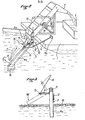
- FIG. 4 is a schematic view, in elevation, of a barge carrying a submerged settling tank, at constant level, with evacuation with manual adjustment,
- FIG. 5 is a plan view of the barge of FIG. 4,
- FIGS. 6A, 6B, 6C and 6D are simplified longitudinal sections of the barge of FIG. 4 in the respectively empty navigation position, at the start of work (tank filled with water), during recovery work and at the end of work.
- Figure 7 is a schematic cross section of a submerged tank barge with automatic overflow compensation.
Sur les figures 1 à 3, une barge 1 porte un appareil 2 de récupération de matières flottantes et une cuve 3 de décantation et de stockage pour lesdites matières qui y sont déversées par l'élévateur de l'appareil 2.In FIGS. 1 to 3, a
Il est clair que la récupération sera plus rapide si l'on crée un courant tendant à diriger la couche de matières flottantes vers l'embouchure 2a de l'appareil 2. Dans ce but, la barge est munie de deux pales 4a, 4b articulées respectivement de part et d'autre de l'embouchure 2 a sur la coque de la barge ou sur l'appareil 2 de récupération comme c'est le cas dans l'exemple représenté. L'articulation de chacune des pales peut être réalisée autour d'un point fixe (rotule), mais certaines rotations doivent être limitées par butées et il est alors préférable de prévoir, comme cela est représenté (figure 2), une articulation autour de trois axes orthogonaux 5, 10 et 11 dont un, 5, est sensiblement vertical. L'axe 5 est l'axe de balayage, l'axe 10 est l'axe de relevage et l'axe 11, l'axe de basculement.It is clear that the recovery will be faster if one creates a current tending to direct the layer of floating matter towards the opening 2a of the
A distance convenable de son articulation, chaque pale porte un bras 9 de manoeuvre dirigé obliquement vers le haut de manière telle que son extrémité 9 a formant poignée peut être saisie par un opérateur embarqué dans la barge.At a suitable distance from its articulation, each blade carries an operating arm 9 directed obliquely upwards so that its
Les pales 4 a et 4b étant écartées l'une de l'autre comme représenté en traits pleins à la figure 1 (position I) et chaque pale présentant sa section droite verticalement (position I de la figure 3), les fait pivoter l'une vers l'autre selon les flèches f1, autour des axes 5, en agissant sur les bras 9 jusqu'à ce que leurs extrémités libres viennent se rencontrer dans le plan médian de la barge dans la position III, après être passées par la position intermédiaire II. Ce mouvement de balayage de la surface du plan d'eau tend à ramener les matières flottantes dans l'axe de la barge. En même temps ces matières sont poussées vers l'embouchure 2 a grâce à des jets 7 d'eau provenant de buses 8 portées par les pales 4a, 4b3 les jets 7 étant de préférence aplatis dans un plan horizontal et dirigés, suivant les flèches f2) sensiblement en direction de ladite embouchure 2 . Chaque pale peut porter une buse 8, comme la pale 4 à la figure a 1, ou une pluralité de buses 8, comme la pale 4b. Toutes les buses sont alimentées par une canalisation flexible avec de l'eau sous pression, grâce à une pompe puisant l'eau sur laquelle flotte la barge.The
Chaque pale porte à son extrémité libre, sur la face tournée vers l'extérieur, un flotteur 16 (figure 2) qui "suit" les mouvements de surface du plan d'eau (la pale jouant autour de l'axe 10) et en même temps crée un couple qui, à la figure 2, tend à faire tourner la pale 4 a autour de l'axe 11 dans le sens direct, appliquant ainsi la pale contre une butée 17 dans la position verticale représentée aux figures 2 et 3.Each blade carries at its free end, on the face facing outwards, a float 16 (FIG. 2) which "follows" the surface movements of the water body (the blade playing around the axis 10) and in at the same time creates a torque which, in FIG. 2, tends to rotate the
Lorsque le mouvement de balayage est terminé (position III, figure 1), il faut revenir à la position I pour recommencer. Pour éviter d'écarter les matières flottantes vers l'arrière lors de ce mouvement de retour, il faut "sortir" les pales de l'eau. Le relevage d'une pale autour de son axe 10, en tirant sur un câble 12 de relevage est une opération relativement longue, nécessitant en outre l'escamotage du bras 9 et l'arrêt des jets 7 et une telle manoeuvre est exécutée pour la mise en navigation de la barge mais pas en cours de travail. Pour effectuer la mise hors d'eau d'une pale en cours de travail on procède à son "basculement" autour de l'axe 11. Une telle opération est représentée à la figure 3, la pale 4 passant de la position I à la position IV (en traits interrompus). Pour réaliser cette manoeuvre il suffit de tirer sur le câble 14 tendu entre l'extrémité d'une manette 15 et l'extrémité d'un bras 13 fixé rigidement à angle droit sur la face intérieure de la pale considérée. Cette traction est obtenue en faisant pivoter la manette 15, ce qui constitue une manoeuvre simple et rapide. Le basculement doit être suffisant pour que la pale ne touche pas la couche 18 de matières flottantes. Lorsque les pales sont toutes deux "basculées", on les écarte l'une de l'autre, puis en ramenant la manette 15 à sa position initiale les pales reprennent leur situation verticale en appui contre les butées 17 et l'on revient ainsi à la position I de la figure 1 pour un nouveau balayage.When the sweeping movement is complete (position III, figure 1), you must return to position I to start again. To avoid spreading the floating material backwards during this return movement, the blades must be "removed" from the water. The raising of a blade around its
Comme il a été dit ci-avant, le rendement de l'appareil 2 dépend également de la profondeur d'immersion de l'embouchure 2 . Lorsque la profondeur d'immersion optimale est connue, il importe de régler en conséquence la position de l'appareil et d'éviter alors les variations du tirant d'eau de la barge pour maintenir cette immersion sensiblement constante.As mentioned above, the efficiency of the
La stabilisation du tirant d'eau de la barge est obtenue grâce aux dispositions représentées aux figures 4 et 7.Stabilization of the draft of the barge is obtained thanks to the arrangements shown in Figures 4 and 7.
Sur ces figures, on retrouve une barge 1 portant un appareil 2 de récupération de matières flottantes et une cuve 3 de décantation et de stockage. Aux figures 4 et 5 est représenté en outre le moteur 20 de propulsion de la barge. Comme ci-avant, les matières flottantes recueillies par l'embouchure 2 a de l'appareil 2 sont transportées par l'élévateur dudit appareil puis déversées dans la cuve 3, ici par l'intermédiaire d'une goulotte 21.In these figures, there is a
La cuve 3 est une cuve dite noyée, c'est-à-dire remplie d'eau au début du travail et cette eau est évacuée au fur et à mesure du déversement du mélange eau + matières flottantes provenant de l'appareil 2.The
Pour que le tirant d'eau H de la barge ne varie pas, il faut qu'il y ait compensation en poids entre les produits déversés par la goulotte 21 et l'eau évacuée de la cuve. La densité des matières flottantes étant le plus souvent relativement voisine de celle de l'eau, on peut qualifier la cuve 3 de cuve noyée à niveau constant lorsque cette compensation est obtenue, mais ce n'est pas parfaitement exact.So that the draft H of the barge does not vary, there must be compensation in weight between the products discharged from the
Le réglage de l'évacuation de l'eau peut être fait manuellement, par exemple à l'aide d'un volant 22 actionnant un obturateur plat 23 disposé au fond de la cuve sur un orifice de sortie 24.The adjustment of the water drainage can be done manually ment, for example using a
Les différentes phases de remplissage de la cuve 3 sont représentées aux figures 6A à 6D.The different filling phases of the
En 6A, la barge est en position de navigation à vide, le tirant d'eau h est faible et la cuve 3 contient peu d'eau dont l'entrée est due éventuellement à une imparfaite étanchéité de l'obturateur 23 (hauteur maximale de l'eau dans la cuve : h).In 6A, the barge is in the empty navigation position, the draft h is weak and the
Arrivé sur le lieu de travail, figure 6B, la cuve est remplie d'eau jusqu'à obtenir le tirant d'eau H convenable et on règle l'immersion de l'embouchure 2a de l'appareil de récupération. L'obturateur 23 est toujours fermé.Arrived at the workplace, FIG. 6B, the tank is filled with water until the suitable draft H is obtained and the immersion of the
A la figure 6C, le travail de récupération des matières flottantes 26 est commencé. L'obturateur 23 est ouvert de façon à dégager partiellement l'orifice 24 pour que l'eau de la cuve s'écoule avec un débit correspondant à celui de l'arrivée du mélange eau + matières. Le réglage de l'ouverture s'effectue par tâtonnements et doit être corrigé de façon intermittente pour maintenir la valeur H du tirant d'eau.In FIG. 6C, the work of recovery of the floating
A la figure 6D la cuve 3 est sensiblement remplie par les matières récupérées. L'opérateur en est prévenu grâce à un tube plongeur 25 dont l'extrémité supérieure dépasse le niveau maximal de remplissage de la cuve et dont l'extrémité inférieure débouche près du fond de la cuve. Lorsque les matières récupérées atteignent le niveau de l'extrémité inférieure du tube, il en passe dans ce dernier et on les voit apparaître en surface en 27 et l'opérateur ferme alors l'obturateur 23.In FIG. 6D, the
Au lieu d'avoir un réglage manuel par l'obturateur 23, on peut prévoir une compensation automatique grâce à un tube de trop-plein 28, comme représenté à la figure 7, plongeant jusqu'au voisinage du fond de la cuve 3 et coudé à angle droit à sa partie supérieure pour déboucher sur l'un des côtés latéraux de la barge. On obtient ainsi à chaque instant une exacte compensation en poids entre l'eau évacuée par l'orifice 29 a du trop-plein et les matières récupérées 26 déversées dans la cuve. Cette compensation étant faite en poids, le niveau atteint dans la cuve par les matières 26 est légèrement supérieur au niveau de l'eau dans le tube de trop-plein, ce dernier niveau étant le niveau initial de l'eau dans la cuve avant le début du travail de récupération. Comme il a été dit ci-avant ce niveau d'eau initial dépend du tirant d'eau H à respecter et il peut donc varier bien que dans des proportions assez faibles. A la figure 7, pour que le niveau de l'orifice du trop-plein puisse être réglé en fonction dudit niveau initial, la partie coudée 29 du trop-plein est emboîtée de façon téléscopique et à frottement doux sur la partie verticale 28 et un lien 30 ou tout autre moyen de retenue ou de blocage permet de la maintenir dans la position choisie. Au lieu de prévoir une partie téléscopique 29 pour le tube de trop-plein, on peut prévoir une partie flexible, ce qui permet également de faire varier le niveau de l'orifice d'évacuation.Instead of having a manual adjustment by the
Claims (7)
Applications Claiming Priority (2)
| Application Number | Priority Date | Filing Date | Title |
|---|---|---|---|
| FR7819943 | 1978-07-04 | ||
| FR7819943A FR2430350B1 (en) | 1978-07-04 | 1978-07-04 |
Publications (3)
| Publication Number | Publication Date |
|---|---|
| EP0006823A2 true EP0006823A2 (en) | 1980-01-09 |
| EP0006823A3 EP0006823A3 (en) | 1980-01-23 |
| EP0006823B1 EP0006823B1 (en) | 1981-10-07 |
Family
ID=9210321
Family Applications (1)
| Application Number | Title | Priority Date | Filing Date |
|---|---|---|---|
| EP79400451A Expired EP0006823B1 (en) | 1978-07-04 | 1979-07-03 | Barge equipped with a device for collecting floating matter |
Country Status (5)
| Country | Link |
|---|---|
| US (1) | US4264444A (en) |
| EP (1) | EP0006823B1 (en) |
| DE (1) | DE2960934D1 (en) |
| ES (1) | ES482195A1 (en) |
| FR (1) | FR2430350B1 (en) |
Cited By (6)
| Publication number | Priority date | Publication date | Assignee | Title |
|---|---|---|---|---|
| FR2684065A1 (en) * | 1991-11-26 | 1993-05-28 | Morillon Corvol Courbot | Boat for recovering floating objects |
| FR2686567A1 (en) * | 1992-01-28 | 1993-07-30 | Carpentier Henry | Marine antipollution surface collector |
| FR2694737A1 (en) * | 1992-08-11 | 1994-02-18 | Eaux Cie Gle | Anti-pollution catamaran for cleaning water of pollutants - includes receivers mounted between two catamaran hulls with pollutants forced towards receivers by front fluid jet ramp |
| FR2698337A1 (en) * | 1992-11-24 | 1994-05-27 | Eaux Cie Gle | Sea scooter for the recovery of floating pollutants. |
| FR2719610A1 (en) * | 1994-05-06 | 1995-11-10 | Bronnec Jean Armand Louis | Device for recovering polluting products spilled on water or on the ground. |
| CN109137864A (en) * | 2018-09-26 | 2019-01-04 | 周楠 | A kind of river corridor restoration river surface duckweed salvaging collection device |
Families Citing this family (42)
| Publication number | Priority date | Publication date | Assignee | Title |
|---|---|---|---|---|
| IT8347828A0 (en) * | 1983-03-01 | 1983-03-01 | Ayroldi Giuseppe | MULTIPURPOSE BOAT FOR COLLECTING FLOATING OILS |
| CA1225288A (en) * | 1985-12-17 | 1987-08-11 | Christopher Ives | Linear propeller |
| US4707253A (en) * | 1986-09-22 | 1987-11-17 | Ray Rowe | Swimming pool skimmer accelerator |
| US4904379A (en) * | 1987-08-18 | 1990-02-27 | Ward John F | Skimmer-diverter assembly for removing debris from swimming pools and the like |
| US4842735A (en) * | 1988-03-21 | 1989-06-27 | Hollis Calvin L | Oil skimming apparatus |
| US5028325A (en) * | 1990-01-04 | 1991-07-02 | Hamilton William R | Water rake |
| US5045216A (en) * | 1990-02-27 | 1991-09-03 | Eller J David | Method, system and collecting vessel for oil spill recovery |
| US5183579A (en) * | 1990-02-27 | 1993-02-02 | Eller J David | Method, system and apparatus for handling substances on or in water |
| NO910920L (en) * | 1991-03-08 | 1992-09-09 | Odd Pettersen | PROCEDURE AND APPARATUS FOR COLLECTING OIL POLLUTION ON A WATER SURFACE. |
| US5194151A (en) * | 1991-10-15 | 1993-03-16 | Broussard David G | Oil skimmer |
| US5890311A (en) * | 1995-12-07 | 1999-04-06 | Willener; John A. | Apparatus and methods for harvesting and cleaning brine shrimp eggs |
| US6115954A (en) * | 1995-12-07 | 2000-09-12 | Willener; John A. | Collection assemblies and methods for use in harvesting brine shrimp eggs |
| US6073382A (en) * | 1995-12-07 | 2000-06-13 | Willener; John A. | Containment boom apparatus and methods for use in harvesting brine shrimp eggs |
| US5863440A (en) * | 1996-05-24 | 1999-01-26 | Abtech Industries, Inc. | Methods for ameliorating oil spills in marine and inland waters |
| DE69827937T2 (en) | 1997-01-10 | 2005-12-22 | Abtech Industries, Inc., Scottsdale | SYSTEMS FOR IMPROVED TREATMENT OF HYDROCARBONS IN AQUEOUS MILIEU |
| US6541569B1 (en) | 1997-01-10 | 2003-04-01 | Abtech Industries, Inc. | Polymer alloys, morphology and materials for environmental remediation |
| US5738036A (en) * | 1997-04-30 | 1998-04-14 | Jones; Nathan | Platform and supporting structures for a boat |
| US6099723A (en) * | 1997-06-06 | 2000-08-08 | Abtech Industries, Inc. | Catchbasin systems for filtering hydrocarbon spills |
| CA2321108C (en) * | 1998-02-18 | 2009-05-26 | Abtech Industries, Inc. | Curb-inlet storm drain systems for filtering trash and hydrocarbons |
| US6080307A (en) * | 1998-09-29 | 2000-06-27 | Abtech Industries, Inc. | Storm drain systems for filtering trash and hydrocarbons |
| US6531059B1 (en) | 2000-10-05 | 2003-03-11 | Abtech Industries, Inc. | Suspended runoff water filter |
| GB0110381D0 (en) * | 2001-04-27 | 2001-06-20 | Fisk Clive S M | Oil slick harvesting |
| US20050242020A1 (en) * | 2002-07-01 | 2005-11-03 | Fisk Clive S M | Oil slick harvester |
| NO20041471A (en) * | 2004-04-07 | 2005-08-15 | Ide Til Produkt As | Method and device for collecting liquid waste on a water surface. |
| NL1029936C2 (en) * | 2005-09-13 | 2007-03-15 | Koseq B V | System for removing oil from a water surface. |
| US20090057217A1 (en) * | 2007-09-05 | 2009-03-05 | Seawax International, Inc. | Apparatus for contaminant recovery |
| EP2389483B1 (en) * | 2009-01-21 | 2017-06-28 | Oilwhale Oy | Device and method for preventing oil damages and alleviating damages |
| US20120009017A1 (en) * | 2010-07-07 | 2012-01-12 | Advanced Innovative Marketing, Inc. | Oil spill reclamation system |
| RU2012129837A (en) * | 2010-08-25 | 2014-09-27 | Робертс С. Внук БРАУН | METHOD AND SYSTEM FOR PROCESSING SHALLOW AND SATURATED SOIL AREAS |
| EP2439341A1 (en) * | 2010-10-07 | 2012-04-11 | Vetco Gray Controls Limited | Removing oil from the surface of a body of water |
| FR2976254B1 (en) * | 2011-06-09 | 2013-07-05 | Ecoceane | SHIP COMPRISING A DEVICE FOR RECOVERING FLOATING OBJECTS |
| CN102582797B (en) * | 2012-03-07 | 2016-04-13 | 青岛科技大学 | A kind of three body contamination removing ship and method for cleaning waterborne |
| US10526055B2 (en) | 2014-10-16 | 2020-01-07 | Ocean Cleaner, LLC | Apparatus and methods for recovering one or more contaminants from a body of water |
| US11371201B1 (en) | 2014-10-16 | 2022-06-28 | Ocean Cleaner, LLC | Systems, apparatus and methods for collecting debris from a body of water |
| US9643692B2 (en) | 2014-10-16 | 2017-05-09 | Ocean Cleaner, LLC | Apparatus and methods for recovering oil from a body of water |
| US10683627B2 (en) | 2014-10-16 | 2020-06-16 | Ocean Cleaner, LLC | Systems, apparatus and methods for collecting and separating floating debris and water from a body of water |
| JP7165975B2 (en) * | 2018-12-21 | 2022-11-07 | 有限会社手島通商 | Offshore Garbage Collection Equipment and Combined Offshore Garbage Collection Equipment |
| KR102253992B1 (en) * | 2020-12-22 | 2021-05-20 | 한국해양과학기술원 | Sea Spill High Viscosity Oil Recovery Device And Its Recovery Method |
| CN112793725B (en) * | 2021-02-01 | 2022-01-11 | 浙江翌明科技有限公司 | Intelligent cleaning machine for water surface garbage floater for unmanned ship and use method thereof |
| CN114303625B (en) * | 2021-12-29 | 2022-09-23 | 安徽双水农业科技有限公司 | Water grass treatment device for paddy field lobster breeding and water grass fishing method |
| FR3135960A1 (en) * | 2022-05-24 | 2023-12-01 | Efinor Sea Cleaner | Vessel for collecting floating algae |
| WO2023227844A1 (en) * | 2022-05-24 | 2023-11-30 | Efinor Sea Cleaner | Ship for gathering floating algae |
Citations (3)
| Publication number | Priority date | Publication date | Assignee | Title |
|---|---|---|---|---|
| FR2157239A5 (en) * | 1971-10-14 | 1973-06-01 | Soler Jean | |
| FR2217483A1 (en) * | 1973-02-15 | 1974-09-06 | World Chem Kk | Floating oil slick collector - comprising a motor-driven pump on main float linked by flexible strip to annular float |
| US4033869A (en) * | 1974-06-05 | 1977-07-05 | Marine Construction & Design Co. | Oil spill confining and directing apparatus and method using water spray booms |
Family Cites Families (6)
| Publication number | Priority date | Publication date | Assignee | Title |
|---|---|---|---|---|
| US3219190A (en) * | 1961-11-16 | 1965-11-23 | Thune Trygve Fridtjof Arnt | Device for collecting flotsam, especially waste oil spillage on a water surface |
| US3259245A (en) * | 1962-09-18 | 1966-07-05 | Surface Separator Systems Inc | Fluid separation method |
| US3715034A (en) * | 1970-05-06 | 1973-02-06 | A Ivanoff | Device for removing oil slicks |
| US3708070A (en) * | 1970-10-02 | 1973-01-02 | Cities Service Oil Co | Oil skimmer |
| US3700108A (en) * | 1971-02-04 | 1972-10-24 | Frank A Richards | Oil skimmer |
| US4033876A (en) * | 1976-02-06 | 1977-07-05 | Diosdado L. Cocjin | Spilled oil retriever and anti-water pollution water craft |
-
1978
- 1978-07-04 FR FR7819943A patent/FR2430350B1/fr not_active Expired
-
1979
- 1979-06-26 US US06/052,327 patent/US4264444A/en not_active Expired - Lifetime
- 1979-07-03 EP EP79400451A patent/EP0006823B1/en not_active Expired
- 1979-07-03 DE DE7979400451T patent/DE2960934D1/en not_active Expired
- 1979-07-04 ES ES482195A patent/ES482195A1/en not_active Expired
Patent Citations (3)
| Publication number | Priority date | Publication date | Assignee | Title |
|---|---|---|---|---|
| FR2157239A5 (en) * | 1971-10-14 | 1973-06-01 | Soler Jean | |
| FR2217483A1 (en) * | 1973-02-15 | 1974-09-06 | World Chem Kk | Floating oil slick collector - comprising a motor-driven pump on main float linked by flexible strip to annular float |
| US4033869A (en) * | 1974-06-05 | 1977-07-05 | Marine Construction & Design Co. | Oil spill confining and directing apparatus and method using water spray booms |
Cited By (10)
| Publication number | Priority date | Publication date | Assignee | Title |
|---|---|---|---|---|
| FR2684065A1 (en) * | 1991-11-26 | 1993-05-28 | Morillon Corvol Courbot | Boat for recovering floating objects |
| FR2686567A1 (en) * | 1992-01-28 | 1993-07-30 | Carpentier Henry | Marine antipollution surface collector |
| FR2694737A1 (en) * | 1992-08-11 | 1994-02-18 | Eaux Cie Gle | Anti-pollution catamaran for cleaning water of pollutants - includes receivers mounted between two catamaran hulls with pollutants forced towards receivers by front fluid jet ramp |
| FR2698337A1 (en) * | 1992-11-24 | 1994-05-27 | Eaux Cie Gle | Sea scooter for the recovery of floating pollutants. |
| WO1994012385A1 (en) * | 1992-11-24 | 1994-06-09 | Compagnie Générale Des Eaux | Skim-cleaning jet ski |
| FR2719610A1 (en) * | 1994-05-06 | 1995-11-10 | Bronnec Jean Armand Louis | Device for recovering polluting products spilled on water or on the ground. |
| WO1995030798A1 (en) * | 1994-05-06 | 1995-11-16 | Jean Armand Louis Bronnec | Device for recovering pollutants spilled on water or on the ground |
| US5647975A (en) * | 1994-05-06 | 1997-07-15 | Bronnec; Jean Armand Louis | Device for recovering pollutants spilled on water or on the ground |
| CN109137864A (en) * | 2018-09-26 | 2019-01-04 | 周楠 | A kind of river corridor restoration river surface duckweed salvaging collection device |
| CN109137864B (en) * | 2018-09-26 | 2020-12-25 | 安徽新宇生态产业股份有限公司 | River surface duckweed fishing and collecting device for river channel ecological restoration |
Also Published As
| Publication number | Publication date |
|---|---|
| ES482195A1 (en) | 1980-04-01 |
| FR2430350A1 (en) | 1980-02-01 |
| EP0006823A3 (en) | 1980-01-23 |
| FR2430350B1 (en) | 1981-10-23 |
| EP0006823B1 (en) | 1981-10-07 |
| DE2960934D1 (en) | 1981-12-17 |
| US4264444A (en) | 1981-04-28 |
Similar Documents
| Publication | Publication Date | Title |
|---|---|---|
| EP0006823B1 (en) | Barge equipped with a device for collecting floating matter | |
| EP0206915A2 (en) | Cleaning apparatus for water surfaces | |
| FR2782284A1 (en) | MOBILE DEVICE FOR CLEANING FLUIDS, ESPECIALLY SEWERS | |
| EP3362619B1 (en) | Device for extracting a swimming pool cleaning apparatus | |
| CA2335478C (en) | Vessel for collecting floating petroleum products, and travelling facility using such vessels | |
| EP0712457B1 (en) | Device for recovering pollutants spilled on water or on the ground | |
| FR2967969A1 (en) | Boat for collection of e.g. plastic bags, has transmission system allowing reversible passage between position of arm used for collection of waste when opening is immersed near water surface, and another position used for draining of waste | |
| FR2552134A1 (en) | FLOATING DRAGON | |
| EP0054498A1 (en) | Installation for dredging a sea bottom, particularly for great depths | |
| FR2487285A1 (en) | APPARATUS FOR SERVICING, REPAIRING, CLEANING AND / OR PAINTING BORDERS OF A BOAT | |
| FR2738178A3 (en) | Cement mixer | |
| FR2471911A1 (en) | CLEANING BARGE | |
| CA2838594A1 (en) | Ship including a device for recovering floating objects | |
| EP0561679B1 (en) | Semi-portable device and installation for distributing granular material | |
| EP0258165A1 (en) | Apparatus for filling and emptying an agricultural liquid manure tank | |
| FR2505803A1 (en) | UNLOADING DEVICE FOR VESSELS CONTAINING BULK GOODS | |
| CH458966A (en) | Diving boat | |
| FR2610959A1 (en) | Device for picking up rubbish off the ground | |
| FR2673121A1 (en) | MIXER. | |
| FR2543595A1 (en) | Craft for cleaning a sewer or similar waste-discharge channel | |
| FR2476012A1 (en) | Water craft operated manually - has paddles made from flexible material attached to vertical arms either side of hull | |
| FR2546040A1 (en) | Device for washing and de-stoning harvested plants, such as beet | |
| FR2614861A1 (en) | Handling means with arms for use in ports | |
| EP1309480A1 (en) | Wind-propelled nautical craft | |
| CH629556A5 (en) | Device for removing snow |
Legal Events
| Date | Code | Title | Description |
|---|---|---|---|
| PUAI | Public reference made under article 153(3) epc to a published international application that has entered the european phase |
Free format text: ORIGINAL CODE: 0009012 |
|
| PUAL | Search report despatched |
Free format text: ORIGINAL CODE: 0009013 |
|
| AK | Designated contracting states |
Designated state(s): BE DE GB IT NL SE |
|
| AK | Designated contracting states |
Designated state(s): BE DE GB IT NL SE |
|
| 17P | Request for examination filed | ||
| ITF | It: translation for a ep patent filed |
Owner name: LENZI & C. |
|
| GRAA | (expected) grant |
Free format text: ORIGINAL CODE: 0009210 |
|
| AK | Designated contracting states |
Designated state(s): BE DE GB IT NL SE |
|
| REF | Corresponds to: |
Ref document number: 2960934 Country of ref document: DE Date of ref document: 19811217 |
|
| RAP2 | Party data changed (patent owner data changed or rights of a patent transferred) |
Owner name: SOCIETE D'EXPLOITATION DES PROCEDES E.G.M.O. (S.E |
|
| PGFP | Annual fee paid to national office [announced via postgrant information from national office to epo] |
Ref country code: DE Payment date: 19840817 Year of fee payment: 6 |
|
| PGFP | Annual fee paid to national office [announced via postgrant information from national office to epo] |
Ref country code: SE Payment date: 19840930 Year of fee payment: 6 Ref country code: BE Payment date: 19840930 Year of fee payment: 6 |
|
| PGFP | Annual fee paid to national office [announced via postgrant information from national office to epo] |
Ref country code: NL Payment date: 19850731 Year of fee payment: 7 |
|
| PG25 | Lapsed in a contracting state [announced via postgrant information from national office to epo] |
Ref country code: SE Effective date: 19860704 |
|
| PG25 | Lapsed in a contracting state [announced via postgrant information from national office to epo] |
Ref country code: BE Effective date: 19860731 |
|
| BERE | Be: lapsed |
Owner name: ETS GENERAUX DE MECANIQUE DE L'OUEST ( EGMO) Effective date: 19860731 |
|
| PG25 | Lapsed in a contracting state [announced via postgrant information from national office to epo] |
Ref country code: NL Effective date: 19870201 |
|
| NLV4 | Nl: lapsed or anulled due to non-payment of the annual fee | ||
| PG25 | Lapsed in a contracting state [announced via postgrant information from national office to epo] |
Ref country code: DE Effective date: 19870401 |
|
| GBPC | Gb: european patent ceased through non-payment of renewal fee | ||
| PG25 | Lapsed in a contracting state [announced via postgrant information from national office to epo] |
Ref country code: GB Free format text: LAPSE BECAUSE OF NON-PAYMENT OF DUE FEES Effective date: 19881118 |
|
| EUG | Se: european patent has lapsed |
Ref document number: 79400451.5 Effective date: 19870518 |
|
| PLBE | No opposition filed within time limit |
Free format text: ORIGINAL CODE: 0009261 |
|
| STAA | Information on the status of an ep patent application or granted ep patent |
Free format text: STATUS: NO OPPOSITION FILED WITHIN TIME LIMIT |