EP0004591B1 - Schalenkatalysatoren, Verfahren zu ihrer Herstellung und ihre Verwendung für die Bereitung von Anthrachinonen - Google Patents
Schalenkatalysatoren, Verfahren zu ihrer Herstellung und ihre Verwendung für die Bereitung von Anthrachinonen Download PDFInfo
- Publication number
- EP0004591B1 EP0004591B1 EP79100838A EP79100838A EP0004591B1 EP 0004591 B1 EP0004591 B1 EP 0004591B1 EP 79100838 A EP79100838 A EP 79100838A EP 79100838 A EP79100838 A EP 79100838A EP 0004591 B1 EP0004591 B1 EP 0004591B1
- Authority
- EP
- European Patent Office
- Prior art keywords
- vanadium
- compounds
- parts
- catalyst
- carrier
- Prior art date
- Legal status (The legal status is an assumption and is not a legal conclusion. Google has not performed a legal analysis and makes no representation as to the accuracy of the status listed.)
- Expired
Links
- 239000003054 catalyst Substances 0.000 title claims description 72
- 238000000034 method Methods 0.000 title claims description 24
- 150000004056 anthraquinones Chemical class 0.000 title claims description 16
- 238000002360 preparation method Methods 0.000 title claims description 10
- 150000001875 compounds Chemical class 0.000 claims description 39
- 239000000203 mixture Substances 0.000 claims description 36
- 239000002245 particle Substances 0.000 claims description 28
- 238000010438 heat treatment Methods 0.000 claims description 22
- 239000007789 gas Substances 0.000 claims description 21
- XLYOFNOQVPJJNP-UHFFFAOYSA-N water Substances O XLYOFNOQVPJJNP-UHFFFAOYSA-N 0.000 claims description 21
- QVGXLLKOCUKJST-UHFFFAOYSA-N atomic oxygen Chemical compound [O] QVGXLLKOCUKJST-UHFFFAOYSA-N 0.000 claims description 14
- 239000011248 coating agent Substances 0.000 claims description 14
- 238000000576 coating method Methods 0.000 claims description 14
- 239000001301 oxygen Substances 0.000 claims description 14
- 229910052760 oxygen Inorganic materials 0.000 claims description 14
- PYKYMHQGRFAEBM-UHFFFAOYSA-N anthraquinone Natural products CCC(=O)c1c(O)c2C(=O)C3C(C=CC=C3O)C(=O)c2cc1CC(=O)OC PYKYMHQGRFAEBM-UHFFFAOYSA-N 0.000 claims description 11
- 229910052751 metal Inorganic materials 0.000 claims description 11
- 239000002184 metal Substances 0.000 claims description 11
- 230000003647 oxidation Effects 0.000 claims description 11
- 238000007254 oxidation reaction Methods 0.000 claims description 11
- PQNFLJBBNBOBRQ-UHFFFAOYSA-N indane Chemical compound C1=CC=C2CCCC2=C1 PQNFLJBBNBOBRQ-UHFFFAOYSA-N 0.000 claims description 10
- 238000004519 manufacturing process Methods 0.000 claims description 7
- 239000000463 material Substances 0.000 claims description 7
- 150000002739 metals Chemical class 0.000 claims description 7
- 239000007787 solid Substances 0.000 claims description 6
- 239000011149 active material Substances 0.000 claims description 2
- 239000001257 hydrogen Substances 0.000 claims 2
- 229910052739 hydrogen Inorganic materials 0.000 claims 2
- UFHFLCQGNIYNRP-UHFFFAOYSA-N Hydrogen Chemical compound [H][H] UFHFLCQGNIYNRP-UHFFFAOYSA-N 0.000 claims 1
- 125000000217 alkyl group Chemical group 0.000 claims 1
- 239000011324 bead Substances 0.000 claims 1
- 229910052736 halogen Inorganic materials 0.000 claims 1
- 150000002367 halogens Chemical class 0.000 claims 1
- 150000002431 hydrogen Chemical class 0.000 claims 1
- GNTDGMZSJNCJKK-UHFFFAOYSA-N divanadium pentaoxide Chemical compound O=[V](=O)O[V](=O)=O GNTDGMZSJNCJKK-UHFFFAOYSA-N 0.000 description 36
- 229910052720 vanadium Inorganic materials 0.000 description 27
- LEONUFNNVUYDNQ-UHFFFAOYSA-N vanadium atom Chemical compound [V] LEONUFNNVUYDNQ-UHFFFAOYSA-N 0.000 description 27
- JHIDJKSBZPNVKZ-UHFFFAOYSA-N 1-methyl-3-phenyl-2,3-dihydro-1h-indene Chemical compound C12=CC=CC=C2C(C)CC1C1=CC=CC=C1 JHIDJKSBZPNVKZ-UHFFFAOYSA-N 0.000 description 16
- GWEVSGVZZGPLCZ-UHFFFAOYSA-N Titan oxide Chemical compound O=[Ti]=O GWEVSGVZZGPLCZ-UHFFFAOYSA-N 0.000 description 16
- 239000007858 starting material Substances 0.000 description 16
- LSGOVYNHVSXFFJ-UHFFFAOYSA-N vanadate(3-) Chemical compound [O-][V]([O-])([O-])=O LSGOVYNHVSXFFJ-UHFFFAOYSA-N 0.000 description 15
- 239000007795 chemical reaction product Substances 0.000 description 13
- 239000000725 suspension Substances 0.000 description 11
- -1 niobs Substances 0.000 description 10
- 238000005096 rolling process Methods 0.000 description 10
- 238000001816 cooling Methods 0.000 description 9
- PAWQVTBBRAZDMG-UHFFFAOYSA-N 2-(3-bromo-2-fluorophenyl)acetic acid Chemical compound OC(=O)CC1=CC=CC(Br)=C1F PAWQVTBBRAZDMG-UHFFFAOYSA-N 0.000 description 8
- 238000010285 flame spraying Methods 0.000 description 8
- 239000007921 spray Substances 0.000 description 8
- 229910052716 thallium Inorganic materials 0.000 description 8
- BKVIYDNLLOSFOA-UHFFFAOYSA-N thallium Chemical compound [Tl] BKVIYDNLLOSFOA-UHFFFAOYSA-N 0.000 description 8
- 235000010215 titanium dioxide Nutrition 0.000 description 8
- UGFAIRIUMAVXCW-UHFFFAOYSA-N Carbon monoxide Chemical compound [O+]#[C-] UGFAIRIUMAVXCW-UHFFFAOYSA-N 0.000 description 7
- 229910052787 antimony Inorganic materials 0.000 description 7
- WATWJIUSRGPENY-UHFFFAOYSA-N antimony atom Chemical compound [Sb] WATWJIUSRGPENY-UHFFFAOYSA-N 0.000 description 7
- ADCOVFLJGNWWNZ-UHFFFAOYSA-N antimony trioxide Chemical compound O=[Sb]O[Sb]=O ADCOVFLJGNWWNZ-UHFFFAOYSA-N 0.000 description 7
- 150000002468 indanes Chemical class 0.000 description 7
- 239000004408 titanium dioxide Substances 0.000 description 7
- XEEYBQQBJWHFJM-UHFFFAOYSA-N Iron Chemical compound [Fe] XEEYBQQBJWHFJM-UHFFFAOYSA-N 0.000 description 6
- MUBZPKHOEPUJKR-UHFFFAOYSA-N Oxalic acid Chemical compound OC(=O)C(O)=O MUBZPKHOEPUJKR-UHFFFAOYSA-N 0.000 description 6
- VYPSYNLAJGMNEJ-UHFFFAOYSA-N Silicium dioxide Chemical class O=[Si]=O VYPSYNLAJGMNEJ-UHFFFAOYSA-N 0.000 description 6
- 238000006243 chemical reaction Methods 0.000 description 6
- VNWKTOKETHGBQD-UHFFFAOYSA-N methane Chemical compound C VNWKTOKETHGBQD-UHFFFAOYSA-N 0.000 description 6
- 239000011541 reaction mixture Substances 0.000 description 6
- 230000003197 catalytic effect Effects 0.000 description 5
- 150000002736 metal compounds Chemical class 0.000 description 5
- CURLTUGMZLYLDI-UHFFFAOYSA-N Carbon dioxide Chemical compound O=C=O CURLTUGMZLYLDI-UHFFFAOYSA-N 0.000 description 4
- ZHNUHDYFZUAESO-UHFFFAOYSA-N Formamide Chemical compound NC=O ZHNUHDYFZUAESO-UHFFFAOYSA-N 0.000 description 4
- XLOMVQKBTHCTTD-UHFFFAOYSA-N Zinc monoxide Chemical compound [Zn]=O XLOMVQKBTHCTTD-UHFFFAOYSA-N 0.000 description 4
- NLSCHDZTHVNDCP-UHFFFAOYSA-N caesium nitrate Chemical compound [Cs+].[O-][N+]([O-])=O NLSCHDZTHVNDCP-UHFFFAOYSA-N 0.000 description 4
- 238000004140 cleaning Methods 0.000 description 4
- 238000001035 drying Methods 0.000 description 4
- 125000004435 hydrogen atom Chemical group [H]* 0.000 description 4
- 229910052738 indium Inorganic materials 0.000 description 4
- APFVFJFRJDLVQX-UHFFFAOYSA-N indium atom Chemical compound [In] APFVFJFRJDLVQX-UHFFFAOYSA-N 0.000 description 4
- 238000002844 melting Methods 0.000 description 4
- 230000000737 periodic effect Effects 0.000 description 4
- FGIUAXJPYTZDNR-UHFFFAOYSA-N potassium nitrate Chemical compound [K+].[O-][N+]([O-])=O FGIUAXJPYTZDNR-UHFFFAOYSA-N 0.000 description 4
- 229910052701 rubidium Inorganic materials 0.000 description 4
- IGLNJRXAVVLDKE-UHFFFAOYSA-N rubidium atom Chemical compound [Rb] IGLNJRXAVVLDKE-UHFFFAOYSA-N 0.000 description 4
- 150000003839 salts Chemical class 0.000 description 4
- 229910052714 tellurium Inorganic materials 0.000 description 4
- PORWMNRCUJJQNO-UHFFFAOYSA-N tellurium atom Chemical compound [Te] PORWMNRCUJJQNO-UHFFFAOYSA-N 0.000 description 4
- WFKWXMTUELFFGS-UHFFFAOYSA-N tungsten Chemical compound [W] WFKWXMTUELFFGS-UHFFFAOYSA-N 0.000 description 4
- 229910052721 tungsten Inorganic materials 0.000 description 4
- 239000010937 tungsten Substances 0.000 description 4
- ZOXJGFHDIHLPTG-UHFFFAOYSA-N Boron Chemical compound [B] ZOXJGFHDIHLPTG-UHFFFAOYSA-N 0.000 description 3
- VYZAMTAEIAYCRO-UHFFFAOYSA-N Chromium Chemical compound [Cr] VYZAMTAEIAYCRO-UHFFFAOYSA-N 0.000 description 3
- PWHULOQIROXLJO-UHFFFAOYSA-N Manganese Chemical compound [Mn] PWHULOQIROXLJO-UHFFFAOYSA-N 0.000 description 3
- ZOKXTWBITQBERF-UHFFFAOYSA-N Molybdenum Chemical compound [Mo] ZOKXTWBITQBERF-UHFFFAOYSA-N 0.000 description 3
- ZLMJMSJWJFRBEC-UHFFFAOYSA-N Potassium Chemical compound [K] ZLMJMSJWJFRBEC-UHFFFAOYSA-N 0.000 description 3
- KWYUFKZDYYNOTN-UHFFFAOYSA-M Potassium hydroxide Chemical compound [OH-].[K+] KWYUFKZDYYNOTN-UHFFFAOYSA-M 0.000 description 3
- HEMHJVSKTPXQMS-UHFFFAOYSA-M Sodium hydroxide Chemical compound [OH-].[Na+] HEMHJVSKTPXQMS-UHFFFAOYSA-M 0.000 description 3
- ATJFFYVFTNAWJD-UHFFFAOYSA-N Tin Chemical compound [Sn] ATJFFYVFTNAWJD-UHFFFAOYSA-N 0.000 description 3
- RTAQQCXQSZGOHL-UHFFFAOYSA-N Titanium Chemical compound [Ti] RTAQQCXQSZGOHL-UHFFFAOYSA-N 0.000 description 3
- 229910052770 Uranium Inorganic materials 0.000 description 3
- HCHKCACWOHOZIP-UHFFFAOYSA-N Zinc Chemical compound [Zn] HCHKCACWOHOZIP-UHFFFAOYSA-N 0.000 description 3
- 229910052785 arsenic Inorganic materials 0.000 description 3
- RQNWIZPPADIBDY-UHFFFAOYSA-N arsenic atom Chemical compound [As] RQNWIZPPADIBDY-UHFFFAOYSA-N 0.000 description 3
- UNTBPXHCXVWYOI-UHFFFAOYSA-O azanium;oxido(dioxo)vanadium Chemical compound [NH4+].[O-][V](=O)=O UNTBPXHCXVWYOI-UHFFFAOYSA-O 0.000 description 3
- 229910052796 boron Inorganic materials 0.000 description 3
- 229910052793 cadmium Inorganic materials 0.000 description 3
- BDOSMKKIYDKNTQ-UHFFFAOYSA-N cadmium atom Chemical compound [Cd] BDOSMKKIYDKNTQ-UHFFFAOYSA-N 0.000 description 3
- 229910052792 caesium Inorganic materials 0.000 description 3
- TVFDJXOCXUVLDH-UHFFFAOYSA-N caesium atom Chemical compound [Cs] TVFDJXOCXUVLDH-UHFFFAOYSA-N 0.000 description 3
- 229910002091 carbon monoxide Inorganic materials 0.000 description 3
- 229910052804 chromium Inorganic materials 0.000 description 3
- 239000011651 chromium Substances 0.000 description 3
- 230000000052 comparative effect Effects 0.000 description 3
- 229910052732 germanium Inorganic materials 0.000 description 3
- GNPVGFCGXDBREM-UHFFFAOYSA-N germanium atom Chemical compound [Ge] GNPVGFCGXDBREM-UHFFFAOYSA-N 0.000 description 3
- 229910052742 iron Inorganic materials 0.000 description 3
- 229910052748 manganese Inorganic materials 0.000 description 3
- 239000011572 manganese Substances 0.000 description 3
- 230000008018 melting Effects 0.000 description 3
- 229910052750 molybdenum Inorganic materials 0.000 description 3
- 239000011733 molybdenum Substances 0.000 description 3
- 229910052700 potassium Inorganic materials 0.000 description 3
- 239000011591 potassium Substances 0.000 description 3
- 238000005507 spraying Methods 0.000 description 3
- 239000000126 substance Substances 0.000 description 3
- 229910052719 titanium Inorganic materials 0.000 description 3
- 239000010936 titanium Substances 0.000 description 3
- DNYWZCXLKNTFFI-UHFFFAOYSA-N uranium Chemical compound [U][U][U][U][U][U][U][U][U][U][U][U][U][U][U][U][U][U][U][U][U][U][U][U][U][U][U][U][U][U][U][U][U][U][U][U][U][U][U][U][U][U][U][U][U][U][U][U][U][U][U][U][U][U][U][U][U][U][U][U][U][U][U][U][U][U][U][U][U][U][U][U][U][U][U][U][U][U][U][U][U][U][U][U][U][U][U][U][U][U][U][U][U][U][U][U][U][U][U][U][U][U][U][U][U][U][U][U][U][U][U][U][U][U] DNYWZCXLKNTFFI-UHFFFAOYSA-N 0.000 description 3
- 238000005406 washing Methods 0.000 description 3
- 229910052725 zinc Inorganic materials 0.000 description 3
- 239000011701 zinc Substances 0.000 description 3
- KHUFHLFHOQVFGB-UHFFFAOYSA-N 1-aminoanthracene-9,10-dione Chemical class O=C1C2=CC=CC=C2C(=O)C2=C1C=CC=C2N KHUFHLFHOQVFGB-UHFFFAOYSA-N 0.000 description 2
- RZVHIXYEVGDQDX-UHFFFAOYSA-N 9,10-anthraquinone Chemical compound C1=CC=C2C(=O)C3=CC=CC=C3C(=O)C2=C1 RZVHIXYEVGDQDX-UHFFFAOYSA-N 0.000 description 2
- PNEYBMLMFCGWSK-UHFFFAOYSA-N Alumina Chemical class [O-2].[O-2].[O-2].[Al+3].[Al+3] PNEYBMLMFCGWSK-UHFFFAOYSA-N 0.000 description 2
- XKRFYHLGVUSROY-UHFFFAOYSA-N Argon Chemical compound [Ar] XKRFYHLGVUSROY-UHFFFAOYSA-N 0.000 description 2
- VEXZGXHMUGYJMC-UHFFFAOYSA-N Hydrochloric acid Chemical compound Cl VEXZGXHMUGYJMC-UHFFFAOYSA-N 0.000 description 2
- WCUXLLCKKVVCTQ-UHFFFAOYSA-M Potassium chloride Chemical compound [Cl-].[K+] WCUXLLCKKVVCTQ-UHFFFAOYSA-M 0.000 description 2
- ATUOYWHBWRKTHZ-UHFFFAOYSA-N Propane Chemical compound CCC ATUOYWHBWRKTHZ-UHFFFAOYSA-N 0.000 description 2
- MCMNRKCIXSYSNV-UHFFFAOYSA-N ZrO2 Inorganic materials O=[Zr]=O MCMNRKCIXSYSNV-UHFFFAOYSA-N 0.000 description 2
- 239000002253 acid Substances 0.000 description 2
- 150000007513 acids Chemical class 0.000 description 2
- HSFWRNGVRCDJHI-UHFFFAOYSA-N alpha-acetylene Natural products C#C HSFWRNGVRCDJHI-UHFFFAOYSA-N 0.000 description 2
- 238000000889 atomisation Methods 0.000 description 2
- 239000013590 bulk material Substances 0.000 description 2
- 239000001569 carbon dioxide Substances 0.000 description 2
- 229910002092 carbon dioxide Inorganic materials 0.000 description 2
- 239000012159 carrier gas Substances 0.000 description 2
- 239000012876 carrier material Substances 0.000 description 2
- JKWMSGQKBLHBQQ-UHFFFAOYSA-N diboron trioxide Chemical compound O=BOB=O JKWMSGQKBLHBQQ-UHFFFAOYSA-N 0.000 description 2
- GLYAPCVEOALCSB-UHFFFAOYSA-L dicesium;tellurate Chemical compound [Cs+].[Cs+].[O-][Te]([O-])(=O)=O GLYAPCVEOALCSB-UHFFFAOYSA-L 0.000 description 2
- KZHJGOXRZJKJNY-UHFFFAOYSA-N dioxosilane;oxo(oxoalumanyloxy)alumane Chemical compound O=[Si]=O.O=[Si]=O.O=[Al]O[Al]=O.O=[Al]O[Al]=O.O=[Al]O[Al]=O KZHJGOXRZJKJNY-UHFFFAOYSA-N 0.000 description 2
- 238000009826 distribution Methods 0.000 description 2
- 125000002534 ethynyl group Chemical group [H]C#C* 0.000 description 2
- 238000001704 evaporation Methods 0.000 description 2
- 230000008020 evaporation Effects 0.000 description 2
- 238000001125 extrusion Methods 0.000 description 2
- 230000005484 gravity Effects 0.000 description 2
- 125000005843 halogen group Chemical group 0.000 description 2
- 238000011068 loading method Methods 0.000 description 2
- 229910052863 mullite Inorganic materials 0.000 description 2
- 239000003345 natural gas Substances 0.000 description 2
- 229910052758 niobium Inorganic materials 0.000 description 2
- 239000010955 niobium Substances 0.000 description 2
- GUCVJGMIXFAOAE-UHFFFAOYSA-N niobium atom Chemical compound [Nb] GUCVJGMIXFAOAE-UHFFFAOYSA-N 0.000 description 2
- 235000006408 oxalic acid Nutrition 0.000 description 2
- 150000002926 oxygen Chemical class 0.000 description 2
- RVTZCBVAJQQJTK-UHFFFAOYSA-N oxygen(2-);zirconium(4+) Chemical compound [O-2].[O-2].[Zr+4] RVTZCBVAJQQJTK-UHFFFAOYSA-N 0.000 description 2
- 239000008188 pellet Substances 0.000 description 2
- 238000007750 plasma spraying Methods 0.000 description 2
- BWHMMNNQKKPAPP-UHFFFAOYSA-L potassium carbonate Chemical compound [K+].[K+].[O-]C([O-])=O BWHMMNNQKKPAPP-UHFFFAOYSA-L 0.000 description 2
- 239000004323 potassium nitrate Substances 0.000 description 2
- 235000010333 potassium nitrate Nutrition 0.000 description 2
- 239000002244 precipitate Substances 0.000 description 2
- 238000001556 precipitation Methods 0.000 description 2
- HBMJWWWQQXIZIP-UHFFFAOYSA-N silicon carbide Chemical compound [Si+]#[C-] HBMJWWWQQXIZIP-UHFFFAOYSA-N 0.000 description 2
- 229910010271 silicon carbide Inorganic materials 0.000 description 2
- 239000002002 slurry Substances 0.000 description 2
- 229910052718 tin Inorganic materials 0.000 description 2
- 239000011135 tin Substances 0.000 description 2
- XOLBLPGZBRYERU-UHFFFAOYSA-N tin dioxide Chemical compound O=[Sn]=O XOLBLPGZBRYERU-UHFFFAOYSA-N 0.000 description 2
- ONDPHDOFVYQSGI-UHFFFAOYSA-N zinc nitrate Chemical compound [Zn+2].[O-][N+]([O-])=O.[O-][N+]([O-])=O ONDPHDOFVYQSGI-UHFFFAOYSA-N 0.000 description 2
- 239000011787 zinc oxide Substances 0.000 description 2
- ICLPNZMYHDVKKI-UHFFFAOYSA-N 1,1,3-trimethyl-3-phenyl-2h-indene Chemical compound C12=CC=CC=C2C(C)(C)CC1(C)C1=CC=CC=C1 ICLPNZMYHDVKKI-UHFFFAOYSA-N 0.000 description 1
- AHBGXHAWSHTPOM-UHFFFAOYSA-N 1,3,2$l^{4},4$l^{4}-dioxadistibetane 2,4-dioxide Chemical compound O=[Sb]O[Sb](=O)=O AHBGXHAWSHTPOM-UHFFFAOYSA-N 0.000 description 1
- XEZSGGPMDZSQBE-UHFFFAOYSA-N 1,3-dimethyl-3-phenyl-1,2-dihydroindene Chemical compound C12=CC=CC=C2C(C)CC1(C)C1=CC=CC=C1 XEZSGGPMDZSQBE-UHFFFAOYSA-N 0.000 description 1
- OGAXRQUHNDEXIN-UHFFFAOYSA-N 1-(2-bromophenyl)-3-methyl-2,3-dihydro-1h-indene Chemical compound C12=CC=CC=C2C(C)CC1C1=CC=CC=C1Br OGAXRQUHNDEXIN-UHFFFAOYSA-N 0.000 description 1
- APBQMVXZLWRCDD-UHFFFAOYSA-N 1-(2-chlorophenyl)-3-methyl-2,3-dihydro-1h-indene Chemical compound C12=CC=CC=C2C(C)CC1C1=CC=CC=C1Cl APBQMVXZLWRCDD-UHFFFAOYSA-N 0.000 description 1
- UIPXXGXXBYHKBV-UHFFFAOYSA-N 1-(2-methylpropyl)-3-phenyl-2,3-dihydro-1h-indene Chemical compound C12=CC=CC=C2C(CC(C)C)CC1C1=CC=CC=C1 UIPXXGXXBYHKBV-UHFFFAOYSA-N 0.000 description 1
- WWMUJCKMKLLLDC-UHFFFAOYSA-N 1-(3-bromophenyl)-3-methyl-2,3-dihydro-1h-indene Chemical compound C12=CC=CC=C2C(C)CC1C1=CC=CC(Br)=C1 WWMUJCKMKLLLDC-UHFFFAOYSA-N 0.000 description 1
- ULOMEEUBWMXHHR-UHFFFAOYSA-N 1-(3-chlorophenyl)-3-methyl-2,3-dihydro-1h-indene Chemical compound C12=CC=CC=C2C(C)CC1C1=CC=CC(Cl)=C1 ULOMEEUBWMXHHR-UHFFFAOYSA-N 0.000 description 1
- FLUOUVQNEJISAW-UHFFFAOYSA-N 1-(4-bromophenyl)-3-methyl-2,3-dihydro-1h-indene Chemical compound C12=CC=CC=C2C(C)CC1C1=CC=C(Br)C=C1 FLUOUVQNEJISAW-UHFFFAOYSA-N 0.000 description 1
- IKGOOOIRZMPWIT-UHFFFAOYSA-N 1-(4-chlorophenyl)-3-methyl-2,3-dihydro-1h-indene Chemical compound C12=CC=CC=C2C(C)CC1C1=CC=C(Cl)C=C1 IKGOOOIRZMPWIT-UHFFFAOYSA-N 0.000 description 1
- HOPBQQIFDUXLFH-UHFFFAOYSA-N 1-phenyl-3-propyl-2,3-dihydro-1h-indene Chemical compound C12=CC=CC=C2C(CCC)CC1C1=CC=CC=C1 HOPBQQIFDUXLFH-UHFFFAOYSA-N 0.000 description 1
- FQBASFNKHFGISU-UHFFFAOYSA-N 4-bromo-1-(2-bromophenyl)-3-methyl-2,3-dihydro-1h-indene Chemical compound C12=CC=CC(Br)=C2C(C)CC1C1=CC=CC=C1Br FQBASFNKHFGISU-UHFFFAOYSA-N 0.000 description 1
- QOFQVFHKMXZYKJ-UHFFFAOYSA-N 4-bromo-3-(3-bromophenyl)-1-methyl-2,3-dihydro-1h-indene Chemical compound C1=CC=C(Br)C2=C1C(C)CC2C1=CC=CC(Br)=C1 QOFQVFHKMXZYKJ-UHFFFAOYSA-N 0.000 description 1
- FAVNNCZOXCLXGD-UHFFFAOYSA-N 4-chloro-1-(2-chlorophenyl)-3-methyl-2,3-dihydro-1h-indene Chemical compound C12=CC=CC(Cl)=C2C(C)CC1C1=CC=CC=C1Cl FAVNNCZOXCLXGD-UHFFFAOYSA-N 0.000 description 1
- HTRLSJXGZGJETH-UHFFFAOYSA-N 4-chloro-3-(3-chlorophenyl)-1-methyl-2,3-dihydro-1h-indene Chemical compound C1=CC=C(Cl)C2=C1C(C)CC2C1=CC=CC(Cl)=C1 HTRLSJXGZGJETH-UHFFFAOYSA-N 0.000 description 1
- GPZDLBMGJKSJNJ-UHFFFAOYSA-N 5-bromo-1-(3-bromophenyl)-3-methyl-2,3-dihydro-1h-indene Chemical compound C12=CC=C(Br)C=C2C(C)CC1C1=CC=CC(Br)=C1 GPZDLBMGJKSJNJ-UHFFFAOYSA-N 0.000 description 1
- VGUBDMWWEAFYCX-UHFFFAOYSA-N 5-bromo-3-(4-bromophenyl)-1-methyl-2,3-dihydro-1h-indene Chemical compound C12=CC(Br)=CC=C2C(C)CC1C1=CC=C(Br)C=C1 VGUBDMWWEAFYCX-UHFFFAOYSA-N 0.000 description 1
- JFEAXFJQKSYJEV-UHFFFAOYSA-N 5-chloro-1-(3-chlorophenyl)-3-methyl-2,3-dihydro-1h-indene Chemical compound C12=CC=C(Cl)C=C2C(C)CC1C1=CC=CC(Cl)=C1 JFEAXFJQKSYJEV-UHFFFAOYSA-N 0.000 description 1
- KPYJALGBNPDENG-UHFFFAOYSA-N 5-chloro-3-(4-chlorophenyl)-1-methyl-2,3-dihydro-1h-indene Chemical compound C12=CC(Cl)=CC=C2C(C)CC1C1=CC=C(Cl)C=C1 KPYJALGBNPDENG-UHFFFAOYSA-N 0.000 description 1
- 239000005995 Aluminium silicate Substances 0.000 description 1
- QGZKDVFQNNGYKY-UHFFFAOYSA-O Ammonium Chemical compound [NH4+] QGZKDVFQNNGYKY-UHFFFAOYSA-O 0.000 description 1
- IJGRMHOSHXDMSA-UHFFFAOYSA-N Atomic nitrogen Chemical compound N#N IJGRMHOSHXDMSA-UHFFFAOYSA-N 0.000 description 1
- BVKZGUZCCUSVTD-UHFFFAOYSA-M Bicarbonate Chemical class OC([O-])=O BVKZGUZCCUSVTD-UHFFFAOYSA-M 0.000 description 1
- WKBOTKDWSSQWDR-UHFFFAOYSA-N Bromine atom Chemical group [Br] WKBOTKDWSSQWDR-UHFFFAOYSA-N 0.000 description 1
- BDAGIHXWWSANSR-UHFFFAOYSA-M Formate Chemical compound [O-]C=O BDAGIHXWWSANSR-UHFFFAOYSA-M 0.000 description 1
- 239000005909 Kieselgur Substances 0.000 description 1
- 229910002651 NO3 Inorganic materials 0.000 description 1
- NHNBFGGVMKEFGY-UHFFFAOYSA-N Nitrate Chemical compound [O-][N+]([O-])=O NHNBFGGVMKEFGY-UHFFFAOYSA-N 0.000 description 1
- LGRFSURHDFAFJT-UHFFFAOYSA-N Phthalic anhydride Natural products C1=CC=C2C(=O)OC(=O)C2=C1 LGRFSURHDFAFJT-UHFFFAOYSA-N 0.000 description 1
- 241001104043 Syringa Species 0.000 description 1
- 235000004338 Syringa vulgaris Nutrition 0.000 description 1
- 238000006887 Ullmann reaction Methods 0.000 description 1
- FMRLDPWIRHBCCC-UHFFFAOYSA-L Zinc carbonate Chemical compound [Zn+2].[O-]C([O-])=O FMRLDPWIRHBCCC-UHFFFAOYSA-L 0.000 description 1
- WNPMJIKMURUYFG-UHFFFAOYSA-N [N+](=O)([O-])[O-].[Ge+2].[N+](=O)([O-])[O-] Chemical compound [N+](=O)([O-])[O-].[Ge+2].[N+](=O)([O-])[O-] WNPMJIKMURUYFG-UHFFFAOYSA-N 0.000 description 1
- LNSPFAOULBTYBI-UHFFFAOYSA-N [O].C#C Chemical group [O].C#C LNSPFAOULBTYBI-UHFFFAOYSA-N 0.000 description 1
- ABUBSBSOTTXVPV-UHFFFAOYSA-H [U+6].CC([O-])=O.CC([O-])=O.CC([O-])=O.CC([O-])=O.CC([O-])=O.CC([O-])=O Chemical compound [U+6].CC([O-])=O.CC([O-])=O.CC([O-])=O.CC([O-])=O.CC([O-])=O.CC([O-])=O ABUBSBSOTTXVPV-UHFFFAOYSA-H 0.000 description 1
- 238000010521 absorption reaction Methods 0.000 description 1
- ZOIORXHNWRGPMV-UHFFFAOYSA-N acetic acid;zinc Chemical compound [Zn].CC(O)=O.CC(O)=O ZOIORXHNWRGPMV-UHFFFAOYSA-N 0.000 description 1
- 239000013543 active substance Substances 0.000 description 1
- 229910052782 aluminium Inorganic materials 0.000 description 1
- 235000012211 aluminium silicate Nutrition 0.000 description 1
- DNEHKUCSURWDGO-UHFFFAOYSA-N aluminum sodium Chemical compound [Na].[Al] DNEHKUCSURWDGO-UHFFFAOYSA-N 0.000 description 1
- 125000003277 amino group Chemical group 0.000 description 1
- 150000003863 ammonium salts Chemical class 0.000 description 1
- 229910052849 andalusite Inorganic materials 0.000 description 1
- LJCFOYOSGPHIOO-UHFFFAOYSA-N antimony pentoxide Inorganic materials O=[Sb](=O)O[Sb](=O)=O LJCFOYOSGPHIOO-UHFFFAOYSA-N 0.000 description 1
- 229910000411 antimony tetroxide Inorganic materials 0.000 description 1
- SZXAQBAUDGBVLT-UHFFFAOYSA-H antimony(3+);2,3-dihydroxybutanedioate Chemical compound [Sb+3].[Sb+3].[O-]C(=O)C(O)C(O)C([O-])=O.[O-]C(=O)C(O)C(O)C([O-])=O.[O-]C(=O)C(O)C(O)C([O-])=O SZXAQBAUDGBVLT-UHFFFAOYSA-H 0.000 description 1
- 239000007900 aqueous suspension Substances 0.000 description 1
- 229910052786 argon Inorganic materials 0.000 description 1
- 239000010425 asbestos Substances 0.000 description 1
- 229910001570 bauxite Inorganic materials 0.000 description 1
- 239000000440 bentonite Substances 0.000 description 1
- 229910000278 bentonite Inorganic materials 0.000 description 1
- SVPXDRXYRYOSEX-UHFFFAOYSA-N bentoquatam Chemical compound O.O=[Si]=O.O=[Al]O[Al]=O SVPXDRXYRYOSEX-UHFFFAOYSA-N 0.000 description 1
- 230000015572 biosynthetic process Effects 0.000 description 1
- 238000004061 bleaching Methods 0.000 description 1
- 238000007664 blowing Methods 0.000 description 1
- 229910001593 boehmite Inorganic materials 0.000 description 1
- 238000009835 boiling Methods 0.000 description 1
- KGBXLFKZBHKPEV-UHFFFAOYSA-N boric acid Chemical compound OB(O)O KGBXLFKZBHKPEV-UHFFFAOYSA-N 0.000 description 1
- 239000004327 boric acid Substances 0.000 description 1
- JHIWVOJDXOSYLW-UHFFFAOYSA-N butyl 2,2-difluorocyclopropane-1-carboxylate Chemical compound CCCCOC(=O)C1CC1(F)F JHIWVOJDXOSYLW-UHFFFAOYSA-N 0.000 description 1
- 239000006227 byproduct Substances 0.000 description 1
- LHQLJMJLROMYRN-UHFFFAOYSA-L cadmium acetate Chemical compound [Cd+2].CC([O-])=O.CC([O-])=O LHQLJMJLROMYRN-UHFFFAOYSA-L 0.000 description 1
- 229910000011 cadmium carbonate Inorganic materials 0.000 description 1
- PLLZRTNVEXYBNA-UHFFFAOYSA-L cadmium hydroxide Chemical compound [OH-].[OH-].[Cd+2] PLLZRTNVEXYBNA-UHFFFAOYSA-L 0.000 description 1
- XIEPJMXMMWZAAV-UHFFFAOYSA-N cadmium nitrate Inorganic materials [Cd+2].[O-][N+]([O-])=O.[O-][N+]([O-])=O XIEPJMXMMWZAAV-UHFFFAOYSA-N 0.000 description 1
- CXKCTMHTOKXKQT-UHFFFAOYSA-N cadmium oxide Inorganic materials [Cd]=O CXKCTMHTOKXKQT-UHFFFAOYSA-N 0.000 description 1
- QCUOBSQYDGUHHT-UHFFFAOYSA-L cadmium sulfate Chemical compound [Cd+2].[O-]S([O-])(=O)=O QCUOBSQYDGUHHT-UHFFFAOYSA-L 0.000 description 1
- 229910000331 cadmium sulfate Inorganic materials 0.000 description 1
- GKDXQAKPHKQZSC-UHFFFAOYSA-L cadmium(2+);carbonate Chemical compound [Cd+2].[O-]C([O-])=O GKDXQAKPHKQZSC-UHFFFAOYSA-L 0.000 description 1
- CFEAAQFZALKQPA-UHFFFAOYSA-N cadmium(2+);oxygen(2-) Chemical compound [O-2].[Cd+2] CFEAAQFZALKQPA-UHFFFAOYSA-N 0.000 description 1
- ZOAIGCHJWKDIPJ-UHFFFAOYSA-M caesium acetate Chemical compound [Cs+].CC([O-])=O ZOAIGCHJWKDIPJ-UHFFFAOYSA-M 0.000 description 1
- ZMCUDHNSHCRDBT-UHFFFAOYSA-M caesium bicarbonate Chemical compound [Cs+].OC([O-])=O ZMCUDHNSHCRDBT-UHFFFAOYSA-M 0.000 description 1
- FJDQFPXHSGXQBY-UHFFFAOYSA-L caesium carbonate Chemical compound [Cs+].[Cs+].[O-]C([O-])=O FJDQFPXHSGXQBY-UHFFFAOYSA-L 0.000 description 1
- 229910000024 caesium carbonate Inorganic materials 0.000 description 1
- ATZQZZAXOPPAAQ-UHFFFAOYSA-M caesium formate Chemical compound [Cs+].[O-]C=O ATZQZZAXOPPAAQ-UHFFFAOYSA-M 0.000 description 1
- 238000001354 calcination Methods 0.000 description 1
- 229910052799 carbon Inorganic materials 0.000 description 1
- 125000004432 carbon atom Chemical group C* 0.000 description 1
- 150000004649 carbonic acid derivatives Chemical class 0.000 description 1
- 239000000969 carrier Substances 0.000 description 1
- 238000006555 catalytic reaction Methods 0.000 description 1
- KFFYRBKJZPSGSD-UHFFFAOYSA-M cesium;2,3-dihydroxybutanedioate;hydron Chemical compound [Cs+].OC(=O)C(O)C(O)C([O-])=O KFFYRBKJZPSGSD-UHFFFAOYSA-M 0.000 description 1
- 229910052801 chlorine Inorganic materials 0.000 description 1
- 150000001805 chlorine compounds Chemical class 0.000 description 1
- 125000001309 chloro group Chemical group Cl* 0.000 description 1
- 239000002826 coolant Substances 0.000 description 1
- 229910052593 corundum Inorganic materials 0.000 description 1
- 239000010431 corundum Substances 0.000 description 1
- IQDXNHZDRQHKEF-UHFFFAOYSA-N dialuminum;dicalcium;dioxido(oxo)silane Chemical compound [Al+3].[Al+3].[Ca+2].[Ca+2].[O-][Si]([O-])=O.[O-][Si]([O-])=O.[O-][Si]([O-])=O.[O-][Si]([O-])=O.[O-][Si]([O-])=O IQDXNHZDRQHKEF-UHFFFAOYSA-N 0.000 description 1
- YNKVVRHAQCDJQM-UHFFFAOYSA-P diazanium dinitrate Chemical compound [NH4+].[NH4+].[O-][N+]([O-])=O.[O-][N+]([O-])=O YNKVVRHAQCDJQM-UHFFFAOYSA-P 0.000 description 1
- DRGYXGZFRXFMHF-UHFFFAOYSA-N diazanium;tellurate Chemical compound [NH4+].[NH4+].[O-][Te]([O-])(=O)=O DRGYXGZFRXFMHF-UHFFFAOYSA-N 0.000 description 1
- HEQUOWMMDQTGCX-UHFFFAOYSA-L dicesium;oxalate Chemical compound [Cs+].[Cs+].[O-]C(=O)C([O-])=O HEQUOWMMDQTGCX-UHFFFAOYSA-L 0.000 description 1
- 230000000447 dimerizing effect Effects 0.000 description 1
- SSWAPIFTNSBXIS-UHFFFAOYSA-N dioxido(dioxo)tungsten;iron(2+) Chemical compound [Fe+2].[O-][W]([O-])(=O)=O SSWAPIFTNSBXIS-UHFFFAOYSA-N 0.000 description 1
- IRXRGVFLQOSHOH-UHFFFAOYSA-L dipotassium;oxalate Chemical compound [K+].[K+].[O-]C(=O)C([O-])=O IRXRGVFLQOSHOH-UHFFFAOYSA-L 0.000 description 1
- SRRYZMQPLOIHRP-UHFFFAOYSA-L dipotassium;tellurate Chemical compound [K+].[K+].[O-][Te]([O-])(=O)=O SRRYZMQPLOIHRP-UHFFFAOYSA-L 0.000 description 1
- 239000000975 dye Substances 0.000 description 1
- 230000000694 effects Effects 0.000 description 1
- 238000005265 energy consumption Methods 0.000 description 1
- 238000011049 filling Methods 0.000 description 1
- 239000000706 filtrate Substances 0.000 description 1
- 238000001914 filtration Methods 0.000 description 1
- 239000003546 flue gas Substances 0.000 description 1
- 229910052731 fluorine Inorganic materials 0.000 description 1
- 125000001153 fluoro group Chemical group F* 0.000 description 1
- 229910001679 gibbsite Inorganic materials 0.000 description 1
- 239000012456 homogeneous solution Substances 0.000 description 1
- 150000004679 hydroxides Chemical class 0.000 description 1
- FAHBNUUHRFUEAI-UHFFFAOYSA-M hydroxidooxidoaluminium Chemical compound O[Al]=O FAHBNUUHRFUEAI-UHFFFAOYSA-M 0.000 description 1
- 238000005470 impregnation Methods 0.000 description 1
- 239000011261 inert gas Substances 0.000 description 1
- LIKBJVNGSGBSGK-UHFFFAOYSA-N iron(3+);oxygen(2-) Chemical compound [O-2].[O-2].[O-2].[Fe+3].[Fe+3] LIKBJVNGSGBSGK-UHFFFAOYSA-N 0.000 description 1
- JEIPFZHSYJVQDO-UHFFFAOYSA-N iron(III) oxide Inorganic materials O=[Fe]O[Fe]=O JEIPFZHSYJVQDO-UHFFFAOYSA-N 0.000 description 1
- NLYAJNPCOHFWQQ-UHFFFAOYSA-N kaolin Chemical compound O.O.O=[Al]O[Si](=O)O[Si](=O)O[Al]=O NLYAJNPCOHFWQQ-UHFFFAOYSA-N 0.000 description 1
- 239000001095 magnesium carbonate Substances 0.000 description 1
- ZLNQQNXFFQJAID-UHFFFAOYSA-L magnesium carbonate Chemical compound [Mg+2].[O-]C([O-])=O ZLNQQNXFFQJAID-UHFFFAOYSA-L 0.000 description 1
- 229910000021 magnesium carbonate Inorganic materials 0.000 description 1
- 235000014380 magnesium carbonate Nutrition 0.000 description 1
- HCWCAKKEBCNQJP-UHFFFAOYSA-N magnesium orthosilicate Chemical compound [Mg+2].[Mg+2].[O-][Si]([O-])([O-])[O-] HCWCAKKEBCNQJP-UHFFFAOYSA-N 0.000 description 1
- 239000000391 magnesium silicate Substances 0.000 description 1
- 229910052919 magnesium silicate Inorganic materials 0.000 description 1
- 235000019792 magnesium silicate Nutrition 0.000 description 1
- 229910044991 metal oxide Inorganic materials 0.000 description 1
- 150000004706 metal oxides Chemical class 0.000 description 1
- 229910000476 molybdenum oxide Inorganic materials 0.000 description 1
- 238000000465 moulding Methods 0.000 description 1
- QNHNSPNFZFBEQR-UHFFFAOYSA-N n'-(3-trihydroxysilylpropyl)ethane-1,2-diamine Chemical compound NCCNCCC[Si](O)(O)O QNHNSPNFZFBEQR-UHFFFAOYSA-N 0.000 description 1
- 150000002823 nitrates Chemical class 0.000 description 1
- JCXJVPUVTGWSNB-UHFFFAOYSA-N nitrogen dioxide Inorganic materials O=[N]=O JCXJVPUVTGWSNB-UHFFFAOYSA-N 0.000 description 1
- FYWSTUCDSVYLPV-UHFFFAOYSA-N nitrooxythallium Chemical compound [Tl+].[O-][N+]([O-])=O FYWSTUCDSVYLPV-UHFFFAOYSA-N 0.000 description 1
- QGLKJKCYBOYXKC-UHFFFAOYSA-N nonaoxidotritungsten Chemical compound O=[W]1(=O)O[W](=O)(=O)O[W](=O)(=O)O1 QGLKJKCYBOYXKC-UHFFFAOYSA-N 0.000 description 1
- 239000003960 organic solvent Substances 0.000 description 1
- 150000003891 oxalate salts Chemical class 0.000 description 1
- FYFRKQBKFGRDSO-UHFFFAOYSA-H oxalate;titanium(3+) Chemical compound [Ti+3].[Ti+3].[O-]C(=O)C([O-])=O.[O-]C(=O)C([O-])=O.[O-]C(=O)C([O-])=O FYFRKQBKFGRDSO-UHFFFAOYSA-H 0.000 description 1
- TWNQGVIAIRXVLR-UHFFFAOYSA-N oxo(oxoalumanyloxy)alumane Chemical compound O=[Al]O[Al]=O TWNQGVIAIRXVLR-UHFFFAOYSA-N 0.000 description 1
- PQQKPALAQIIWST-UHFFFAOYSA-N oxomolybdenum Chemical compound [Mo]=O PQQKPALAQIIWST-UHFFFAOYSA-N 0.000 description 1
- OOAWCECZEHPMBX-UHFFFAOYSA-N oxygen(2-);uranium(4+) Chemical compound [O-2].[O-2].[U+4] OOAWCECZEHPMBX-UHFFFAOYSA-N 0.000 description 1
- 239000003973 paint Substances 0.000 description 1
- 235000011837 pasties Nutrition 0.000 description 1
- 238000005453 pelletization Methods 0.000 description 1
- 239000000575 pesticide Substances 0.000 description 1
- NMHMNPHRMNGLLB-UHFFFAOYSA-N phloretic acid Chemical compound OC(=O)CCC1=CC=C(O)C=C1 NMHMNPHRMNGLLB-UHFFFAOYSA-N 0.000 description 1
- 239000000049 pigment Substances 0.000 description 1
- 238000009832 plasma treatment Methods 0.000 description 1
- 239000011148 porous material Substances 0.000 description 1
- 235000015497 potassium bicarbonate Nutrition 0.000 description 1
- 229910000028 potassium bicarbonate Inorganic materials 0.000 description 1
- 239000011736 potassium bicarbonate Substances 0.000 description 1
- 229910000027 potassium carbonate Inorganic materials 0.000 description 1
- 235000011181 potassium carbonates Nutrition 0.000 description 1
- 239000001103 potassium chloride Substances 0.000 description 1
- 235000011164 potassium chloride Nutrition 0.000 description 1
- TYJJADVDDVDEDZ-UHFFFAOYSA-M potassium hydrogencarbonate Chemical compound [K+].OC([O-])=O TYJJADVDDVDEDZ-UHFFFAOYSA-M 0.000 description 1
- BFPJYWDBBLZXOM-UHFFFAOYSA-L potassium tellurite Chemical compound [K+].[K+].[O-][Te]([O-])=O BFPJYWDBBLZXOM-UHFFFAOYSA-L 0.000 description 1
- 239000000843 powder Substances 0.000 description 1
- 239000001294 propane Substances 0.000 description 1
- 239000008262 pumice Substances 0.000 description 1
- 239000010453 quartz Substances 0.000 description 1
- 239000002994 raw material Substances 0.000 description 1
- 229910052895 riebeckite Inorganic materials 0.000 description 1
- WPFGFHJALYCVMO-UHFFFAOYSA-L rubidium carbonate Chemical compound [Rb+].[Rb+].[O-]C([O-])=O WPFGFHJALYCVMO-UHFFFAOYSA-L 0.000 description 1
- 229910000026 rubidium carbonate Inorganic materials 0.000 description 1
- RTHYXYOJKHGZJT-UHFFFAOYSA-N rubidium nitrate Inorganic materials [Rb+].[O-][N+]([O-])=O RTHYXYOJKHGZJT-UHFFFAOYSA-N 0.000 description 1
- 229910052624 sepiolite Inorganic materials 0.000 description 1
- 235000019355 sepiolite Nutrition 0.000 description 1
- 239000000741 silica gel Substances 0.000 description 1
- 229910002027 silica gel Inorganic materials 0.000 description 1
- 150000004760 silicates Chemical class 0.000 description 1
- 239000000377 silicon dioxide Substances 0.000 description 1
- 238000002791 soaking Methods 0.000 description 1
- JVBXVOWTABLYPX-UHFFFAOYSA-L sodium dithionite Chemical compound [Na+].[Na+].[O-]S(=O)S([O-])=O JVBXVOWTABLYPX-UHFFFAOYSA-L 0.000 description 1
- 150000003440 styrenes Chemical class 0.000 description 1
- 238000000859 sublimation Methods 0.000 description 1
- 230000008022 sublimation Effects 0.000 description 1
- 238000003786 synthesis reaction Methods 0.000 description 1
- XHGGEBRKUWZHEK-UHFFFAOYSA-L tellurate Chemical compound [O-][Te]([O-])(=O)=O XHGGEBRKUWZHEK-UHFFFAOYSA-L 0.000 description 1
- LAJZODKXOMJMPK-UHFFFAOYSA-N tellurium dioxide Chemical compound O=[Te]=O LAJZODKXOMJMPK-UHFFFAOYSA-N 0.000 description 1
- IIXQANVWKBCLEB-UHFFFAOYSA-N tellurium trioxide Chemical compound O=[Te](=O)=O IIXQANVWKBCLEB-UHFFFAOYSA-N 0.000 description 1
- HQOJMTATBXYHNR-UHFFFAOYSA-M thallium(I) acetate Chemical compound [Tl+].CC([O-])=O HQOJMTATBXYHNR-UHFFFAOYSA-M 0.000 description 1
- DASUJKKKKGHFBF-UHFFFAOYSA-L thallium(i) carbonate Chemical compound [Tl+].[Tl+].[O-]C([O-])=O DASUJKKKKGHFBF-UHFFFAOYSA-L 0.000 description 1
- ZCUFMDLYAMJYST-UHFFFAOYSA-N thorium dioxide Chemical compound O=[Th]=O ZCUFMDLYAMJYST-UHFFFAOYSA-N 0.000 description 1
- 230000001988 toxicity Effects 0.000 description 1
- 231100000419 toxicity Toxicity 0.000 description 1
- WYXIGTJNYDDFFH-UHFFFAOYSA-Q triazanium;borate Chemical compound [NH4+].[NH4+].[NH4+].[O-]B([O-])[O-] WYXIGTJNYDDFFH-UHFFFAOYSA-Q 0.000 description 1
- KHAUBYTYGDOYRU-IRXASZMISA-N trospectomycin Chemical compound CN[C@H]([C@H]1O2)[C@@H](O)[C@@H](NC)[C@H](O)[C@H]1O[C@H]1[C@]2(O)C(=O)C[C@@H](CCCC)O1 KHAUBYTYGDOYRU-IRXASZMISA-N 0.000 description 1
- 229910001930 tungsten oxide Inorganic materials 0.000 description 1
- FCTBKIHDJGHPPO-UHFFFAOYSA-N uranium dioxide Inorganic materials O=[U]=O FCTBKIHDJGHPPO-UHFFFAOYSA-N 0.000 description 1
- WQEVDHBJGNOKKO-UHFFFAOYSA-K vanadic acid Chemical compound O[V](O)(O)=O WQEVDHBJGNOKKO-UHFFFAOYSA-K 0.000 description 1
- 150000003682 vanadium compounds Chemical class 0.000 description 1
- 239000000984 vat dye Substances 0.000 description 1
- 239000002912 waste gas Substances 0.000 description 1
- 239000010457 zeolite Substances 0.000 description 1
- 239000004246 zinc acetate Substances 0.000 description 1
- 229910000010 zinc carbonate Inorganic materials 0.000 description 1
- 239000011667 zinc carbonate Substances 0.000 description 1
- 235000004416 zinc carbonate Nutrition 0.000 description 1
- SRWMQSFFRFWREA-UHFFFAOYSA-M zinc formate Chemical compound [Zn+2].[O-]C=O SRWMQSFFRFWREA-UHFFFAOYSA-M 0.000 description 1
- UGZADUVQMDAIAO-UHFFFAOYSA-L zinc hydroxide Chemical compound [OH-].[OH-].[Zn+2] UGZADUVQMDAIAO-UHFFFAOYSA-L 0.000 description 1
- 229910021511 zinc hydroxide Inorganic materials 0.000 description 1
- 229940007718 zinc hydroxide Drugs 0.000 description 1
- NWONKYPBYAMBJT-UHFFFAOYSA-L zinc sulfate Chemical compound [Zn+2].[O-]S([O-])(=O)=O NWONKYPBYAMBJT-UHFFFAOYSA-L 0.000 description 1
- 229910000368 zinc sulfate Inorganic materials 0.000 description 1
- 229960001763 zinc sulfate Drugs 0.000 description 1
- ZPEJZWGMHAKWNL-UHFFFAOYSA-L zinc;oxalate Chemical compound [Zn+2].[O-]C(=O)C([O-])=O ZPEJZWGMHAKWNL-UHFFFAOYSA-L 0.000 description 1
Classifications
-
- B—PERFORMING OPERATIONS; TRANSPORTING
- B01—PHYSICAL OR CHEMICAL PROCESSES OR APPARATUS IN GENERAL
- B01J—CHEMICAL OR PHYSICAL PROCESSES, e.g. CATALYSIS OR COLLOID CHEMISTRY; THEIR RELEVANT APPARATUS
- B01J23/00—Catalysts comprising metals or metal oxides or hydroxides, not provided for in group B01J21/00
- B01J23/16—Catalysts comprising metals or metal oxides or hydroxides, not provided for in group B01J21/00 of arsenic, antimony, bismuth, vanadium, niobium, tantalum, polonium, chromium, molybdenum, tungsten, manganese, technetium or rhenium
- B01J23/20—Vanadium, niobium or tantalum
- B01J23/22—Vanadium
-
- B—PERFORMING OPERATIONS; TRANSPORTING
- B01—PHYSICAL OR CHEMICAL PROCESSES OR APPARATUS IN GENERAL
- B01J—CHEMICAL OR PHYSICAL PROCESSES, e.g. CATALYSIS OR COLLOID CHEMISTRY; THEIR RELEVANT APPARATUS
- B01J37/00—Processes, in general, for preparing catalysts; Processes, in general, for activation of catalysts
- B01J37/02—Impregnation, coating or precipitation
- B01J37/0215—Coating
- B01J37/0221—Coating of particles
- B01J37/0223—Coating of particles by rotation
-
- C—CHEMISTRY; METALLURGY
- C07—ORGANIC CHEMISTRY
- C07C—ACYCLIC OR CARBOCYCLIC COMPOUNDS
- C07C46/00—Preparation of quinones
- C07C46/02—Preparation of quinones by oxidation giving rise to quinoid structures
-
- B—PERFORMING OPERATIONS; TRANSPORTING
- B01—PHYSICAL OR CHEMICAL PROCESSES OR APPARATUS IN GENERAL
- B01J—CHEMICAL OR PHYSICAL PROCESSES, e.g. CATALYSIS OR COLLOID CHEMISTRY; THEIR RELEVANT APPARATUS
- B01J35/00—Catalysts, in general, characterised by their form or physical properties
- B01J35/30—Catalysts, in general, characterised by their form or physical properties characterised by their physical properties
- B01J35/396—Distribution of the active metal ingredient
- B01J35/397—Egg shell like
Definitions
- the invention relates to new coated catalysts and processes for their production by atomizing mixtures of water and vanadium-V compounds and, if appropriate, further metal compounds and application to carrier particles that are in their own motion, drying and repeated short-term treatment of the catalysts in their own motion with flame or plasma and rapid cooling under certain conditions of application speed.
- shell catalysts for catalytic reactions which are composed of supports, e.g. B. in the form of balls, tablets or extrusions, the surface of which is shell. l shaped with a catalytically active mass. Non-porous or slightly porous inert materials are used as carriers. These supports are coated with the active composition in such a way that the catalytically active substances are mixed with water or an organic solvent to form a slurry and the support, which is kept in motion, for example, in a coating drum, is coated by gradually adding the slurry.
- shell catalysts are obtained, the shell thickness of which is between approximately 0.02 to 4 millimeters. Then the catalysts coated with the active components have to be heated to higher temperatures for a long time.
- shell catalysts consisting of a support and a layer of catalytically active composition applied thereon, can be produced by applying the catalytically active composition to the support by means of the plasma spraying or flame spraying process .
- the carrier particles are advantageously spherical in order to keep the pressure loss in the reactor low. You can e.g. B. be made in a pelletizing drum.
- a prerequisite for the application of the method is the meltability of at least one main component at the working temperature of the flame spray burner, which is operated with acetylene / oxygen. or the plasma torch.
- the process is carried out in such a way that the active components or the substances which can be decomposed into the desired oxidic and catalytically active compounds at the working temperature of the burners are introduced into the flame or the plasma jet in a known manner.
- the flame or the plasma jet is directed onto the particles to be coated, which are preferably, for. B. kept in motion in a rotating drum.
- the catalysts thus prepared are, for. B. used for the oxidation of indanes, wherein vanadium pentoxide layers or layers of molybdenum oxide and / or tungsten oxide are applied to carrier particles as catalytically active layers.
- the examples show that, compared to conventional processes, the catalytic action of the coated catalysts can be increased considerably by adding the catalytic mass, e.g. B. vanadium pentoxide powder, as a molten mass on flame spray or P! Asma burner sprayed onto the carrier and optionally then calcining the catalyst for one hour at 650 to 700 ° C.
- the comparative example shows an application of the catalytic mass to the carrier balls by means of an atomizer at a temperature of 200 ° C .; the coated balls are then heated at 200, 300, 500 and 700 ° C. in an air atmosphere for one hour each.
- the catalysts obtained in this known manner by atomization provide only a yield of 13.8 percent compared to the yields of the process described in DE-A-2 045 430 (45 percent).
- the active mass In the plasma and flame spray processes, the active mass must be fed to the burner by means of pneumatic conveying. This type of feed requires a free-flowing material and can only be carried out without any problems if the grain area of the active mass is approximately between 50 and 200 ⁇ m and the individual grain is as spherical as possible. The production of such a grain shape and grain distribution is difficult on an industrial scale. It is best achieved by melting and then spraying the active material with a gas stream, the spray material being returned with a particle size of ⁇ 50 g and> 200 ⁇ .
- the carrier material By adding the carrier material before or during the precipitation Metal vanadate finely distributed on the carrier at the same time.
- the solution or suspension of the vanadate can also be applied to the support by soaking or spraying. It is also possible to mix the dry and moist vanadate with the carrier, optionally to crush the mixture and then, for. B. with the help of an extruder to convert into corresponding moldings. After drying, the catalyst can advantageously be calcined, for. B. at a temperature between 300 and 700 ° C.
- vanadium pentoxide catalysts one can e.g. B. dissolve vanadium pentoxide in aqueous oxalic acid or hydrochloric acid and the solution on a suitable carrier, for.
- German patents 2050797, 2 122 664, 2135421 and German Offenlegungsschrift 2224016 also teach as an advantageous method of working to apply the active composition to the carrier by means of flame spraying or plasma spraying methods and then the catalyst at 450 to 650 ° C, preferably from 500 to 600 ° C to calcine for 1 to 24 hours.
- DE-A-2 547 624 describes the preparation of supported catalysts which contain rubidium, antimony, vanadium pentoxide and titanium dioxide.
- the corresponding metal compounds of pasty consistency are, for. B. sprayed in a coating drum on the preheated to 100 to 450 ° C carrier. If necessary, the mixture is reheated at 200 to 500 ° C.
- DE-A-2 547 635 describes catalysts which contain vanadium pentoxide and titanium dioxide and / or zirconium dioxide. The metal compounds can be sprayed as a suspension onto the support heated to 160 to 500 ° C. If appropriate, the catalyst is calcined at 300 to 700 ° C. in a further operation.
- coated catalysts consisting of a non-porous or slightly porous support and a layer of catalytically active composition containing vanadium V compounds applied thereon, atomizing vanadium V compounds and, if desired, other metal compounds in a mixture with water and applying the thus atomized material to carrier particles that are in constant self-movement, advantageously obtained if the material is at a temperature of 20 to 90 ° C. and with an application rate of 0.001 to 0.02 parts by weight of solid per volume of carrier balls per minute a!
- the coated catalysts are advantageous for the preparation of anthrachions by oxidation of indanes of the formula in which R 1 , R 2 and R 3 can be the same or different and each represent an alkyl radical, R 1 and / or R 3 can also each denote a hydrogen atom, the radicals X and Y can be the same or different and each one Halogen atom or a hydrogen atom, with oxygen in the gas phase in the presence of vanadium V compounds and, if desired, of one or more compounds of other metals.
- the invention is based on the observation that optimal vanadium shell catalysts, which are particularly suitable for the oxidation of indanes to anthrachions, are not solely based on their composition with regard to the additional elements and their weight relations to the proportion of vanadium, but are also essentially based on a specific combination of features of the catalyst structure, which are particularly determined by the following factors: application of suspensions at a specific application speed and application temperature, rolling self-movement of the carrier during application; Treatment of the catalyst within a selected and short period of time at very high temperature, which causes the vanadium pentoxide and, if appropriate, the additional metal oxides and vanadates within the catalytically active composition to melt in whole or in part during this period; Carrying out this heat treatment in the form of a flame spray or plasma spray treatment; rapid cooling under certain temperature conditions; repeated repetition of heating and cooling of the catalyst surface.
- the process according to the invention provides coated catalysts containing vanadium pentoxide in a simpler and more economical way. If the catalysts are used for the oxidation of indanes, the corresponding anthraquinones are obtained in good yield and purity. The promotion of the active mass via the flame spraying device is avoided, since this is only used for short-term heating of the catalyst bowl; Accordingly, the pourability, grain size and structure of the active mass play no or only a minor role. You can e.g. B. Use grain sizes of the active mass from 50 microns to less than 1 micron, which are unsuitable for the flame spraying process. A special preparation of the active particles, e.g. B.
- vanadium-V compounds preferably vanadium pentoxide and / or vanadates
- the vanadium-V compound can optionally also be present in the catalyst in a mixture with the corresponding vanadium-IV compound.
- the vanadates can be mono- or poly-vanadates, in particular ortho-, pyro-, metavanadates.
- the vanadates of elements from groups la, Ilb, lila, IIIb, IVa, IVb, Va, Vb, Vla, Vlb, Vllb and Vlllb of the periodic table are preferred, in particular ammonium, potassium, thallium, boron , Tellurium, cadmium, germanium, niobium, lead, rubidium, chromium, tungsten, uranium, arsenic, indium, cesium, zinc, molybdenum, iron, titanium, tin -, antimony and manganese vanadate.
- vanadium-V compounds in a mixture with oxides of elements from groups la, IIb, IIIa, Illb, IVa, IVb, Va, Vb, Via, Vlb, Vllb and / or Vlllb of the periodic system (periodic system according to d'Ans -Lax, paperback for chemists and physicists, 3rd edition (1967), volume I, page 63) for the implementation as an active mass, advantageously with the oxides of potassium, thallium, boron, tellurium, cadmium, germanium, niobs, Lead, rubidium, chromium, tungsten, uranium, arsenic, indium, cesium, zinc, molybdenum, iron, titanium, tin, antimony and manganese.
- vanadium V compounds and additional compounds of elements which form vanadates and / or oxides under the reaction conditions are suitable, for.
- the atomic ratio of vanadium to the additional elements in group la is expedient in the catalyst from 2000 to 0.5 vanadium to 1 additional element in the group purple from 4000 to 1 vanadium to 1 additional element, in group IVa from 2000 to 0.1 vanadium to 1 additional element, in group Va from 2000 to 1 vanadium to 1 additional element, in group Vla from 2000 to 1 vanadium to 1 additional element , in group Vllb from 2000 to 3 vanadium to 1 additional element, in group Vlllb from 100000 to 0.5 vanadium to 1 additional element, in group Ilb from 2000 to 3 vanadium to 1 additional element, in group Illb from 2000 to 1 Vanadium to 1 additional element, in group IVb from 2000 to 0.1 vanadium to 1 additional element, in group Vb from 4000 to 5 vanadium to 1 additional element and in group VIb from 2000 to 4 vanadium to 1 additional element.
- the compounds of the additional elements can be chosen arbitrarily, in general the oxides, acids, bases, salts, for. B. carbonates, bicarbonates, oxalates, chlorides or nitrates, ammonium salts of metal acids, and those compounds of the additional elements into question that react during the catalyst preparation to the corresponding oxides and / or vanadates.
- Antimony and thallium are particularly advantageous additional elements.
- An atomic ratio of 30,000 to 10, in particular 6,000 to 25, vanadium to 1 thallium and from 8,000 to 3, in particular 1,600 to 8, vanadium to 1 antimony is preferred.
- As additional connections one expediently chooses those with a Mp below 1200 ° C.
- Such compounds are particularly preferred in cases where the additional element is present in the catalyst in a larger amount. If necessary, a plasma torch should be used for higher melting connections. In this case, a partial reduction of the vanadium-V to vanadium-IV is appropriately avoided in order to prevent the formation of higher-melting vandium-IV.
- Suitable additional compounds are: potassium chloride, potassium carbonate, boron trioxide, thallium nitrate, boric acid, potassium hydroxide, antimony trioxide, antimony tetroxide, pentoxide, antimony trioxide hydrates, antimony pentoxide hydrates, potassium nitrate, potassium bicarbonate, potassium oxalate, formate, germanium nitrate, ammonium nitrate, ammonium nitrate, ammonium nitrate, ammonium nitrate, ammonium nitrate, ammonium nitrate, ammonium nitrate, ammonium nitrate, ammonium ammonium nitrate, ammonium ammonium nitrate, uranium acetate, indium, uranium dioxide, thallium acetate, thallium carbonate, Thalliumvanadat, ammonium borate, cesium carbonate, cesium nitrate, cesium bicarbonate,
- one or more additional compounds e.g. B. oxides, other elements, preferably the aforementioned compounds, for. B. oxides, the aforementioned elements, be present in the catalyst.
- additional compounds e.g. B. oxides, other elements, preferably the aforementioned compounds, for. B. oxides, the aforementioned elements.
- combinations of compounds of vanadium V with compounds of 2, 3, 4 or 5 elements are also advantageous.
- the combination of the compounds of vanadium, antimony and thallium is particularly preferred.
- salts of the metals mentioned with oxygen acids which are formed from corresponding metals mentioned above, such as tungsten; for example, iron tungstate, cesium tellurate, rubidium tungstate are suitable. If appropriate, vanadium can only exist in the form of vanadates of the preferred metals.
- Non-porous or slightly porous materials e.g. B. silica compounds such as silicates, e.g. B. sodium aluminum silicate, magnesium silicate, calcium aluminum silicate, bleaching earth, fuller's earth, clays, kaolin, meerschaum, allophanes, zeolites, montmorrilonite, pumice, Florida earth, quartz, asbestos, mullite, steatite, bentonite; precipitated silica, silica gel, diatomaceous earth, silicon carbide; ⁇ and y aluminum oxides and hydroxides; e.g. B.
- silicates e.g. B. sodium aluminum silicate, magnesium silicate, calcium aluminum silicate, bleaching earth, fuller's earth, clays, kaolin, meerschaum, allophanes, zeolites, montmorrilonite, pumice, Florida earth, quartz, asbestos, mullite, steatite, bentonite
- precipitated silica silica
- the preferred carrier material is mullite, silicon carbide, cc aluminum oxide and in particular steatite. You can also the oxygen-containing connection of an additional element, for. B. titanium (IV) oxide or iron (III) oxide, simultaneously use as a carrier for the catalytically active composition.
- the shape and size of the carrier particles can be chosen in a wide range, z. B.
- the catalytically active composition (vanadium-V compounds, optionally together with the additional compounds) is expediently applied to the carrier in an amount of 0.02 to 0.5, preferably 0.15 to 0.25 parts by weight per part by volume of carrier.
- the active composition (vanadium-V compounds and, if appropriate, compounds of the additional elements) is atomized in the form of an aqueous suspension, advantageously in a suspension of from 7 to 70% by weight, preferably from 20 to 40% by weight.
- injector mixers jet mixers, swirl chamber nozzles, eccentric nozzles, bundle nozzles, centrifugal pressure nozzles, slot nozzles, flat jet nozzles, hollow nozzles, spiral nozzles and in particular atomizing nozzles, two-substance nozzles, rotary atomizers, impact nozzles, full cone atomizers, rotating atomizing nozzles, rotating atomizing nozzles, rotating atomizing nozzles, rotating atomizing nozzles, rotating atomizing nozzles, rotating atomizing nozzles, rotating atomizing nozzles, rotating atomizing nozzles, rotating atomizing nozzles, rotating atomizing nozzles, rotating atomizing nozzles, rotating atomizing nozzles -Jets, hollow cone nozzle.
- the carrier in the form of the aforementioned carrier particles is in its own constant motion during the application.
- this constant self-movement is achieved by rotating containers with a disc-shaped bottom, e.g. B. turntables, rotating drums, coating plates, impregnating drums or coating drums, spiral stirrers or mixers, on the bottom of which the carrier particles are located.
- the angle to the horizontal depends on the device used; when using coating or turntables, set the bottom of the container with the carrier particles at an angle to the horizontal, expediently 30 to 70 °, preferably 40 to 50 °, and in addition to the external movement of the particles by the rotating floor, additionally achieves a constant considerable inherent motion by means of gravity.
- Edged particles will therefore roll over constantly during the movement, round particles, especially rings or balls, will perform a rolling, possibly rotating movement. Since the particles constantly prevent one another from linear movement due to collisions, all of these moments of motion result in a rolling total movement of the carrier particles, as can also be observed, for example, when coating bulk material in coating drums. The more easily rolling particles such as rings and in particular balls are therefore also preferred.
- a difference to impregnation and coating with solutions is seen in the method according to the invention in particular in that the application takes place with a mixture of active composition and water, in which the mass particles in the water completely or are partially undissolved and accordingly form a suspension.
- the suspension is advantageously at a temperature of 10 to 90 ° C., the temperature when the active composition is applied, advantageously measured as the temperature inside the bed, is advantageously from 20 to 90 ° C., in particular 40 to 70 ° C.
- the bed is the total mass of the particles to be coated or the total mass of the shell catalysts, the surface of the total amount is referred to as the bed surface.
- the atomized suspension is sprayed onto the rolling carrier particles at such a rate that 0.001 to 0.02, preferably 0.005 to 0.015 parts by weight of solid per volume of carrier balls are applied per minute. Due to the constant rolling movement, a comparatively uniform layer of active mass is applied at the same time.
- the carrier particles Due to the rotational movement of the apparatus, the carrier particles are lifted up by wall frictional forces and, if necessary, internals and, due to gravity, roll off the surface of the bed or form the surface of the bed.
- the apparatus is expediently filled to 20 to 80 percent by volume with carrier particles during the application; the rotation of the bottom of the container depends on the apparatus used and its size and is generally 2 to 70 revolutions per minute.
- the particles are then dried by direct or indirect heating, expediently until the bed temperature has reached 100 to 110 ° C., advantageously in the same or a similar rotating container, preferably a rotating plate or rotating drum.
- the remaining amount of water in the active composition is advantageously 1 to 10 percent by weight, based on the active composition (calculated as a solid). It is advantageous to dry completely or partially during the application, e.g. B. by blowing in air or inert gas, advantageously at a temperature of 100 to 300 ° C.
- the flame heating or plasma heating of the shell catalysts is carried out by means of a gas or plasma torch directed onto the bed surface of the particles, the individual shell catalysts likewise being located in rotating containers, expediently in the same rotating containers, advantageously rotating plates, impregnating drums or coating drums.
- the above information is advantageous with regard to the angle of the container bottom to the horizontal, the degree of filling, the rotation of the bottom, the temperature inside the bulk material below 650 ° C., advantageously between 650 and 300 ° C., advantageously 650 and 500 ° C., preferably 650 and 600 ° C.
- the flame or plasma beam hits each part (segment) of the surface of each individual shell catalyst only briefly, heats this segment to a temperature above 700 ° C, preferably between 700 and 3000 ° C, suitably between 700 and 1500 ° C, in particular between 700 and 1000 ° C (heating temperature), keeps it briefly at this temperature, then the heated segments are replaced by other segments of other coated catalysts, which in turn are now brought to the heating temperature according to the invention.
- the individual segments are expediently brought to the heating temperature from the temperature inside the bed for 0.1 to 1 seconds and kept at the heating temperature.
- the shell catalysts thus displaced quickly return to the temperature inside the bed on the surface of their heated segments.
- Each segment of the coated catalytic converters expediently cools to the cooling temperature for 0.1 to 1 second after heating. H. to the temperature inside the bed, and remains at this temperature until the next heating step.
- the rolling movement thus subjects all segments of all catalysts to repeated treatment with the flame jet or plasma jet and subsequent rapid cooling. Therefore, forms of shell catalysts that promote smooth rolling motion are preferred, i. H. Round shapes, especially ring-shaped, cylindrical and suitably spherical or approximately spherical (e.g. pellets) coated catalysts are particularly advantageous.
- 10 to 1000, preferably 20 to 200, kg of shell catalysts are used both in the coating step and in the heating by means of flame or plasma treatment, and in accordance therewith a total treatment time of the shell catalysts with the gas or plasma torch of 2 to 60, preferably 10 to 30 minutes.
- the flame of the gas burner can e.g. B. with methane / oxygen, propane / oxygen, natural gas / oxygen and advantageously with acetylene / oxygen or natural gas / oxygen. Air can also be used instead of oxygen.
- Diameters of the container bottom are advantageous when using turntables of 0.5 to 5, in particular 0.5 to 2 meters, distances of the burners from the surface to the bed of 2 to 70, preferably 30 to 60 centimeters, flame temperatures of 700 to 2000 ° C. .
- coated catalysts thus obtained are advantageously used for the production of anthraquinones by oxidation of indanes, expediently according to the procedures described in the abovementioned patents, and have a high activity and selectivity.
- the aforementioned preferred vanadium compounds and, if desired, further preferred metal compounds and the aforementioned quantitative ratios are advantageously used.
- the indanes used as starting materials I can be obtained by dimerizing substituted or unsubstituted styrenes, e.g. B. by the method described in the aforementioned publications or in Rabjohn, Organic Syntheses, Collective Volume IV (John Wiley Inc., New York 1963), pages 665 ff.
- Preferred Indane I and, accordingly, preferred anthraquinones of the formula are those in the formulas R 1 , R 2 , R 3 may be the same or different and each represent an alkyl radical having 1 to 4 carbon atoms, R 1 and / or R 3 may also each denote a hydrogen atom, the radicals X and Y can be the same or different and each designate a bromine atom, a fluorine atom or in particular a hydrogen atom or a chlorine atom.
- Suitable indanes I are e.g. B.
- the oxidation is usually carried out with an excess of oxygen.
- a ratio of 15 to 400 moles of oxygen per mole of indane I over the stoichiometric amount is preferred.
- oxygen is used in the form of air, and any mixtures of oxygen and gases which are inert under the reaction conditions, such as argon, water vapor, nitrogen and / or carbon dioxide or flue gas, can also be used.
- the loading is 5 to 100, advantageously 10 to 60, in particular 25 to 55 grams of starting material I per one normal cubic meter of air.
- the loading can preferably be 5 to 100, advantageously 20 to 70, in particular 30 to 60 grams of starting material I per one normal cubic meter of air.
- 20 to 2000, preferably 40 to 1000, advantageously 60 to 600 grams of starting material I are advantageously oxidized per liter of catalyst per hour.
- the same amounts of starting material I, based on the catalyst, are generally also used in batch operation.
- the oxidation is generally carried out at a temperature between 200 and 500 ° C., preferably between 250 and 470 ° C., in particular between 350 and 470 ° C., without pressure or under pressure, discontinuously or preferably continuously.
- This temperature is usually the temperature of the cooling medium, e.g. B. a saltpetre, measured (tube wall temperature).
- the starting material I in the following manner: The starting Indan I is evaporated and mixed with a suitably heated air stream at 200 to 400 ° C. It is also possible to saturate an oxygen-free partial stream of the reaction waste gases with the vapor of the starting material and thus to set the desired concentration of indane I in the reaction mixture.
- the gas / vapor mixture is then passed through the catalyst layer in a reactor at the reaction temperature.
- Suitable reactors are tube reactors cooled with a salt bath, fluidized bed reactors with built-in cooling elements, or layer reactors with intermediate cooling.
- the end product is now separated from the reaction mixture in a conventional manner, for. B. passing the gases leaving the reactor through one or more separators to separate the anthraquinone from most of the by-products. If necessary, cleaning of the end product is possible by e.g. B.
- the anthraquinone is preferably separated from the mixture of its vapor with a cracked carrier gas by the process described in German Patent No. 2,232,453 by heating the mixture of anthraquinone vapor and carrier gas heated to a temperature of at least 200 ° C. with an aqueous, optionally ammoniacal Anthraquinone suspension treated below the boiling point of water at the prevailing pressure.
- the anthraquinones that can be produced according to the invention are valuable starting materials for the production of dyes and pesticides.
- the corresponding aminoanthraquinones can be obtained from the mono- and dihaloanthraquinones by known processes by exchanging the halogen atoms for amino groups, from which numerous valuable vat dyes and lightfast paint pigments are derived, such as from 1-aminoanthraquinone.
- the parts listed in the following example are parts by weight. They relate to parts by volume like grams to milliliters.
- vanadium pentoxide 4.0 parts are dissolved in 200 parts of water with the addition of 10.0 parts of oxalic acid, 96 parts of titanium dioxide and 32 parts of formamide are added and the suspension formed is applied to 5.4 mm diameter steatite balls (heated to 300 ° C.).
- a coated ball contains 4 parts of active mass (vanadium pentoxide and titanium dioxide) and 96 parts of carrier.
- the active mass is composed of 96% by weight of titanium dioxide and 4% by weight of vanadium pentoxide.
- 600 parts of steatite rings with an outer diameter of 8 mm, a length of 6 mm and a wall thickness of 1.5 mm are heated in a coating drum to 260 ° C. and with a suspension consisting of 400 g of anatase, 31 parts of vanadium pentoxide, 500 parts of water, 100 parts of formamide, 0.89 parts of rubidium carbonate and 10.85 parts of antimony trioxide are sprayed until the weight of the applied catalytically active composition is 10% of the total weight of the catalyst.
- the vanadium pentoxide content of the supported catalyst is 0.70% by weight.
Landscapes
- Chemical & Material Sciences (AREA)
- Organic Chemistry (AREA)
- Engineering & Computer Science (AREA)
- Materials Engineering (AREA)
- Chemical Kinetics & Catalysis (AREA)
- Catalysts (AREA)
- Organic Low-Molecular-Weight Compounds And Preparation Thereof (AREA)
Description
- Die Erfindung betrifft neue Schalenkatalysatoren und Verfahren zu ihrer Herstellung durch Zerstäubung von Gemischen aus Wasser und Vanadium-V-Verbindungen und gegebenenfalls weiteren Metallverbindungen und Auftrag auf sich in Eigenbewegung befindende Trägerteilchen, Trocknung sowie wiederholte kurzfristige Behandlung der sich in Eigenbewegung befindlichen Katalysatoren mit Flammen oder Plasma und rasche Abkühlung unter bestimmten Bedingungen der Auftragsgeschwindigkeit.
- Es ist bekannt, für katalystische Reaktionen Schalenkatalysatoren zu verwenden, die aus Trägern, z. B. in Form von Kugeln, Tabletten oder Strangpreßlingen bestehen, deren Oberfläche schale.lförmig mit einer katalytisch aktiven Masse belegt ist. Als Träger werden nicht poröse oder wenig poröse inerte Materialien verwendet. Die Beschichtung dieser Träger mit der aktiven Masse erfolgt in der Weise, daß man die katalytisch aktiven Substanzen mit Wasser oder einem organischen Lösungsmittel zu einem Brei anrührt und den beispielsweise in einer Dragiertrommel in Bewegung gehaltenen Träger durch allmähliche Zugabe des Breies beschichtet. Hierbei werden Schalenkatalysatoren erhalten, deren Schalendicke zwischen etwa 0,02 bis 4 Millimeter liegt. Anschließend müssen die mit den aktiven Komponenten beschichteten Katalysatoren längere Zeit auf höhere Temperaturen erhitzt werden.
- Aus der DE-A-2 045 430 ist bekannt, daß man Schalenkatalysatoren, bestehend aus einem Träger und einer darauf aufgebrachten Schicht aus katalytisch aktiver Masse dadurch herstellen kann, daß man die katalytisch aktive Masse mit Hilfe des Plasmaspritz- oder Flammspritzverfahrens auf den Träger aufbringt. Wie die Patentschrift angibt, sind die Trägerteilchen vorteilhaft kugelförmig, um den Druckverlust im Reaktor niedrig zu halten. Sie können z. B. in einer Pelletisiertrommel hergestellt sein. Voraussetzung für die Anwendung des Verfahrens ist die Schmelzbarkeit mindestens einer Hauptkomponente bei der Arbeitstemperatur des Flammspritzbrenners, der mit Acetylen/Sauerstoff betrieben wird. oder des Plasmabrenners. Das Verfahren wird in der Weise durchgeführt, daß man die aktiven Komponenten oder die Substanzen, die sich bei der Arbeitstemperatur der Brenner in die gewünschten oxidischen und katalytisch aktiven Verbindungen zersetzen lassen, in die Flamme bzw. den Plasmastrahl in bekannter Weise einbringt. Die Flamme bzw. der Plasmastrahl wird auf die zu beschichtenden Teilchen gerichtet, die vorzugsweise z. B. in einer rotierenden Trommel in Bewegung gehalten werden. Die so hergestellten Katalysatoren werden z. B. für die Oxidation von Indanen verwendet, wobei als katalytisch aktive Schichten Vanadinpentoxidschichten oder Schichten aus Molybdänoxid und/oderWolframoxid auf Trägerteilchen aufgebracht werden.
- In den Beispielen wird gezeigt, daß im Vergleich zu üblichen Verfahren die katalytische Wirkung der Schalenkatalysatoren erheblich gerade dadurch gesteigert werden kann, daß man die katalytische Masse, z. B. Vanadinpentoxidpulver, als geschmolzene Masse über Flammspritz- oder P!asmabrenner auf den Träger aufspritzt und gegebenenfalls anschließend den Katalysator noch eine Stunde bei 650 bis 700° C kalziniert. Denn das Vergleichsbeispiel zeigt einen Auftrag der katalytischen Masse mittels Zerstäuber auf die Trägerkugeln bei einer Temperatur von 200°C; die beschichteten Kugeln werden dann jeweils eine Stunde lang auf 200, 300, 500 und 700° C in Luftatmosphäre erhitzt. Die auf diese bekannte Weise des Auftrags mittels Zerstäubung erhaltenen Katalysatoren liefern im Vergleich zu den Ausbeuten des in der DE-A-2 045 430 beschriebenen Verfahrens (45 Prozent) nur eine Ausbeute von 13,8 Prozent.
- Obwohl das vorgenannte Verfahren im Hinblick auf ältere Verfahren bessere Ergebnisse, insbesondere in der Ausbeute an Endstoff, liefert, ist es doch nicht völlig befriedigend. Beim Plasma-und beim Flammspritzverfahren muß die aktive Masse dem Brenner mittels pneumatischer Förderung zugeführt werden. Diese Art der Zuführung erfordert ein gut rieselfähiges Material und läßt sich nur dann völlig störungsfrei durchführen, wenn der Kornbereich der aktiven Masse etwa zwischen 50 und 200 um liegt und das Einzelkorn möglichst kugelförmig ist. Die Herstellung einer solchen Kornform und Kornverteilung ist im großtechnischen Maßstab mit Schwierigkeiten verbunden. Sie gelingt am besten durch Schmelzen und anschließendes Versprühen der aktiven Masse mit einem Gasstrom, wobei das Sprühgut mit einer Körnung < 50 g und > 200 µ zurückgeführt wird. Nachteilig ist bei dieser Herstellung der optimalen Kornverteilung der hohe Energieverbrauch sowie die wegen der Giftigkeit von z. B. Vanadin erforderlich werdende kostspielige Gasreinigung mittels Wäsche und Elektroabscheider. Eine ähnlich aufwendige Gasreinigung ist aber auch für den Flammspritzvorgang selber erforderlich, da nur 50 bis 70 Prozent der dem Brenner zugeführten aktiven Masse auf den Trägerkugeln aufgeschmolzen wird; der Rest muß aus dem Abgas zurückgewonnen werden.
- Es ist aus den DE-A-1 934 063, 2 028 424, 2 050 797, 2 060 215, 2 122 664, 2 135 421, 2 160 781, 2 314 695 und der deutschen Offenlegungsschrift 2224016 bekannt, daß man vorteilhaft Indane in Gegenwart von Vanadinpentoxid und/oder Vandaten von weiteren Elementen oxidiert. Es wird beschrieben, daß die Katalysatoren durch Fällung oder durch Eindampfen einer Lösung von Ammoniumvanadat mit den entsprechenden Metallsalzen, z. B. Lösungen von Antimontartrat, Ferrinitrat und Caesiumnitrat oder von Rubidiumnitrat und Titan-(III)-oxalat, Filtration und Trocknen des Metallvanadatniederschlags hergestellt werden können. Durch Zugabe des Trägermaterials vor oder während der Fällung wird das Metallvanadat gleichzeitig auf dem Träger fein verteilt. Ebenfalls kann die Lösung oder Suspension des Vanadats durch Tränken oder Sprühen auf den Träger aufgebracht werden. Auch ist es möglich, das trockene und feuchte Vanadat mit dem Träger zu vermischen, gegebenenfalls das Gemisch zu zerkleinern und dann, z. B. mit Hilfe einer Strangpresse, in entsprechende Formlinge überzuführen. Nach dem Trocknen kann der Katalysator noch vorteilhaft calciniert werden, z. B. bei einer Temperatur zwischen 300 und 700°C. Zur Herstellung von Vanadinpentoxidkatalysatoren kann man z. B. Vanadinpentoxid in wäßriger Oxalsäure oder Salzsäure lösen und die Lösung auf einen geeigneten Träger, z. B. Titandioxid oder Steatit, auftragen, den Träger trocknen und gegebenenfalls calcinieren. Entsprechend kann man auch Lösungen von Ammoniumvanadat in Wasser verwenden. Jedoch wird ausdrücklich darauf hingewiesen, z. B. schon in der deutschen Patentschrift 2 028 424, daß sich als besonders vorteilhafte Ausführungsform die Herstellung der Katalysatoren auf kugelförmigen Trägern nach einem Flammspritz- oder Plasmaspritzverfahren, z. B. nach dem in der deutschen Patentschrift 2025430 beschriebenen Verfahren, erweist. Die vorgenannten Verbindungen anderer Elemente können mit dem mittels Flammspritzen aufzubringenden Vanadinpentoxid oder einer Verbindung, die beim Erhitzen in Vanadinpentoxid übergeht, wie z. B. Vanadinsäure, mechanisch vermischt werden. Es wird jedoch ebenfalls als vorteilhaft beschrieben, zunächst eine homogene Lösung herzuste!Ien, die die aufzutragenden Metalle enthält. Aus dieser Lösung können die aufzutragenden Verbindungen, z. B. durch Eindampfen, gewonnen werden. Wie die Beispiele, z. B. die in der deutschen Patentschrift 2028424 beschriebenen, zeigen, wird in der Regel eine katalytische Masse aus Verbindungen vorgenannter Elemente hergestellt und diese dann durch Flammspritzen in der Arbeitsweise der deutschen Patentschrift 2025430 auf den Träger aufgebracht. Die deutschen Patentschriften 2050797, 2 122 664, 2135421 und die deutsche Offenlegungsschrift 2224016 lehren daneben als vorteilhafte Arbeitsweise, die aktive Masse mittels Flammspritz- oder Plasmaspritzverfahren auf den Träger aufzubringen und den Katalysator anschließend bei 450 bis 650° C, vorzugsweise von 500 bis 600° C, während 1 bis 24 Stunden zu calcinieren.
- Die DE-A-2 547 624 beschreibt die Herstellung von Trägerkatalysatoren, die Rubidium, Antimon, Vanadiumpentoxid und Titandioxid enthalten. Die entsprechenden Metallverbindungen von breiförmiger Konsistenz werden z. B. in einer Dragiertrommel auf den auf 100 bis 450° C vorerhitzten Träger aufgesprüht. Gegebenenfalls wird noch bei 200 bis 500° C nacherhitzt. Die DE-A-2 547 635 beschreibt Katalysatorei., die Vanadinpentoxid und Titandioxid und/oder Zirkondioxid enthalten. Die Metallverbindungen können als Suspension auf den auf 160 bis 500°C erhitzten Träger aufgesprüht werden, gegebenenfalls wird in weiterer Operation der Katalysator bei 300 bis 700° C calciniert.
- Es wurde nun gefunden, daß man Schalenkatalysatoren, bestehend aus einem nicht oder wenig porösen Träger und einer darauf aufgebrachten Schicht aus katalytisch aktiver, Vanadium-V-Verbindungen enthaltender Masse, wobei man Vanadium-V-Verbindungen und gewünschtenfalls andere Metallverbindungen im Gemisch mit Wasser zerstäubt und das so zerstäubte Gut auf sich in ständiger Eigenbewegung befindende Trägerteilchen aufbringt, vorteilhaft erhält, wenn man das Gut bei einer Temperatur von 20 bis 90° C und mit einer Auftragsgeschwindigkeit von 0,001 bis 0,02 Gewichtsteilen Feststoff je Volumenteil Trägerkugeln mal Minute a!s Schale aufträgt, dann die so erhaltenen Schalenkatalysatoren trocknet und mit einer Gesamtbehandlungszeit der Schalenkatalysatoren von 2 bis 60 Minuten mittels einer Flammerhitzung oder Plasmaerhitzung der sich in ständiger Eigenbewegung befindenden Schalenkatalysatoren wiederholt alle Teile der Katalysatoroberfläche kurzfristig auf eine Temperatur oberhalb 700°C erhitzt und während 0,1 bis 1 Sekunde auf eine Temperatur unterhalb 650° C abkühlt.
- Weiterhin wurde gefunden, daß man die Schalenkatalysatoren vorteilhaft zur Herstellung von Anthrachionen durch Oxidation von Indanen der Formel
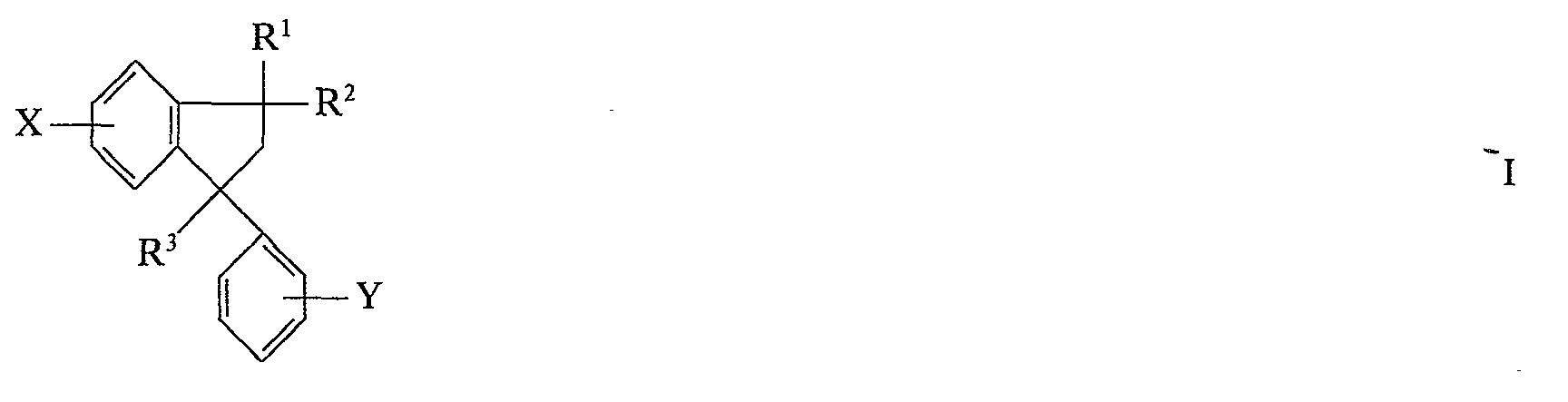
- Die Erfindung beruht auf der Beobachtung, daß optimale Vanadiumschalenkatalysatoren, die besonders für die Oxidation von Indanen zu Anthrachionen geeignet sind, nicht allein auf ihrer Zusammensetzung bezüglich der Zusatzelemente und ihrer Gewichtsrelationen zum Anteil an Vanadin, sondern wesentlich auch auf einer spezifischen Kombination von Merkmalen der Katalysatorstruktur beruhen, die von den folgenden Faktoren besonders bestimmt werden: Auftrag von Suspensionen bei bestimmter Auftragsgeschwindigkeit und Auftragstemperatur, rollender Eigenbewegung des Trägers beim Auftrag; Behandlung des Katalysators innerhalb eines ausgewählten und kurzen Zeitraumes bei sehr hoher Temperatur, die das Vanadinpentoxid und gegebenenfalls die zusätzlichen Metalloxide und -vanadate innerhalb der katalytisch aktiven Masse ganz oder teilweise während dieses Zeitraumes zum Schmelzen bringt; Durchführung dieser Hitzebehandlung in Form einer Flammspritz- oder Plasmaspritzbehandlung; rasche Abkühlung unter bestimmten Bedingungen der Temperatur; mehrfache Wiederholung von Erhitzung und Abkühlung der Katalysatoroberfläche. Im Hinblick auf die bekannten Verfahren liefert das Verfahren nach der Erfindung auf einfacherem und wirtschaftlicherem Wege Vanadinpentoxid enthaltende Schalenkatalysatoren. Verwendet man die Katalysatoren zur Oxidation von Indanen, so erhält man die entsprechenden Anthrachinone in guter Ausbeute und Reinheit. Die Förderung der aktiven Masse über das Flammspritzgerät wird vermieden, da dieses nur zur kurzfristigen Erhitzung der Katalysatorschale verwendet wird; entsprechend spielen Rieselfähigkeit, Korngröße und Struktur der aktiven Masse vergleichsweise keine oder nur eine weit geringere Rolle. Man kann z. B. Korngrößen der aktiven Masse von 50 Mikrometern bis weniger als 1 Mikrometer verwenden, die für das Flammspritzverfahren unzweckmäßig sind. Eine besondere Zubereitung der aktiven Teilchen, z. B. durch Schmelzen und Versprühen der aktiven Masse im Gasstrom wird vermieden, Energie wird eingespart, zusätzliche Reinigungsoperationen des Abgases sind nicht notwendig. Da die aktive Masse nicht über das Flammspritzgerät zerstäubt wird, gelangen entsprechende Anteile nicht in das Abgas und brauchen deshalb nicht abgetrennt und zurückgeführt werden. Die Katalysatoren sind daher gerade im großtechnischen Maßstab einfacher, störungssicherer, wirtschaftlicher und umweltfreundlicher herzustellen. Im Vergleich zu den gemäß DE-A-2 547 624 und DE-A-2 547 655 erhältlichen Ausbeuten ist die erfindungsgemäße Ausbeute wesentlich höher. Alle diese vorteilhaften erfindungsgemäßen Ergebnisse sind im Hinblick auf den Stand der Technik überraschend.
- Als aktive Masse verwendet man eine oder mehrere Vanadium-V-Verbindungen, vorzugsweise Vanadinpentoxid und/oder Vanadate. Die Vanadium-V-Verbindung kann im Katalysator gegebenenfalls auch im Gemisch mit der entsprechenden Vanadium-IV-Verbindung vorliegen. Die Vanadate können Mono- oder Poly-vanadate, insbesondere Ortho-, Pyro-, Metavanadate, sein. Unter den Vanadaten sind die Vanadate von Elementen der Gruppen la, Ilb, lila, IIIb, IVa, IVb, Va, Vb, Vla, Vlb, Vllb und Vlllb des Periodischen Systems bevorzugt, insbesondere Ammonium-, Kalium-, Thallium-, Bor-, Tellur-, Cadmium-, Germanium-, Niob-, Blei-, Rubidium-, Chrom-, Wolfram-, Uran-, Arsen-, Indium-, Caesium-, Zink-, Molybdän-, Eisen-, Titan-, Zinn-, Antimon- und Mangan-vanadat. Ebenfalls kommen Vanadium-V-Verbindungen im Gemisch mit Oxiden von Elementen der Gruppen la, IIb, IIIa, Illb, IVa, IVb, Va, Vb, Via, Vlb, Vllb und/oder Vlllb des Periodischen Systems (Periodisches System gemäß d'Ans-Lax, Taschenbuch für Chemiker und Physiker, 3. Auflage (1967), Band I, Seite 63) für die Umsetzung als aktive Masse in Betracht, vorteilhaft mit den Oxiden des Kaliums, Thalliums, Bors, Tellurs, Cadmiums, Germaniums, Niobs, Bleis, Rubidiums, Chrom, Wolframs, Urans, Arsens, Indiums, Caesiums, Zinks, Molybdäns, Eisens, Titans, Zinns, Antimons und Mangans.
- Auch Gemische von Vanadium-V-Verbindungen und zusätzlichen Verbindungen von Elementen, die unter den Reaktionsbedingungen Vanadate und/oder Oxide bilden, sind geeignet, z. B. eine oder mehrere Vanadin-V-Verbindungen und eine oder mehrere Verbindungen von Elementen der Gruppen la, IIb, lila, Illb, IVa, lVb, Va, Vb, Vla, Vlb, Vllb und/oder VIIIb des Periodischen Systems, insbesondere Verbindungen des Kaliums, Thalliums, Bors, Tellurs, Cadmiums, Germaniums, Niobs, Bleis, Rubidiums, Chroms, Wolframs, Urans, Arsens, Indiums, Caesiums, Zinks, Molybdäns, Eisens, Titans, Zinns, Antimons und Mangans.
- Unabhängig von der Zusammensetzung der Verbindungen und der Wertigkeit der entsprechenden Metalle in den Verbindungen, die die aktive Masse enthält, ist im Katalysator zweckmäßig das Atomverhältnis von Vanadin zu den Zusatzelementen der Gruppe la von 2000 bis 0,5 Vanadium zu 1 Zusatzelement, in der Gruppe lila von 4000 bis 1 Vanadium zu 1 Zusatzelement, in der Gruppe IVa von 2000 bis 0,1 Vanadium zu 1 Zusatzelement, in der Gruppe Va von 2000 bis 1 Vanadium zu 1 Zusatzelement, in der Gruppe Vla von 2000 bis 1 Vanadium zu 1 Zusatzelement, in der Gruppe Vllb von 2000 bis 3 Vanadium zu 1 Zusatzelement, in der Gruppe Vlllb von 100000 bis 0,5 Vanadium zu 1 Zusatzelement, in der Gruppe Ilb von 2000 bis 3 Vanadium zu 1 Zusatzelement, in der Gruppe Illb von 2000 bis 1 Vanadium zu 1 Zusatzelement, in der Gruppe IVb von 2000 bis 0,1 Vanadium zu 1 Zusatzelement, in der Gruppe Vb von 4000 bis 5 Vanadium zu 1 Zusatzelement und in der Gruppe Vlb von 2000 bis 4 Vanadium zu 1 Zusatzelement.
- Die Verbindungen der Zusatzelemente können beliebig gewählt werden, im allgemeinen kommen die Oxide, Säuren, Basen, Salze, z. B. Carbonate, Bicarbonate, Oxalate, Chloride oder Nitrate, Ammoniumsalze von Metallsäuren, und solche Verbindungen der Zusatzelemente in Frage, die sich während der Katalysatorherstellung zu den entsprechenden Oxiden und/oder Vanadaten umsetzen. Besonders vorteilhafte Zusatzelemente sind Antimon und Thallium. Bevorzugt ist ein Atomverhältnis von 30 000 bis 10, insbesondere 6000 bis 25 Vanadium zu 1 Thallium und von 8000 bis 3, insbesondere 1600 bis 8 Vanadium zu 1 Antimon. Als Zusatzverbindungen wählt man zweckmäßig solche mit einem Fp unterhalb 1200°C. Solche Verbindungen sind insbesondere in den Fällen, in denen das Zusatzelement in größerer Menge im Katalysator vorliegt, bevorzugt. Gegebenenfalls ist bei höherschmelzenden Verbindungen ein Plasmabrenner zu verwenden. In diesem Falle vermeidet man zweckmäßig eine teilweise Reduktion des Vanadium-V zu Vanadium-IV, um die Bildung von höherschmelzendem Vandium-IV zu verhindern.
- Als Zusatzverbindungen sind beispielsweise geeignet: Kaliumchlorid, Kaliumcarbonat, Bortrioxid, Thalliumnitrat, Borsäure, Kaliumhydroxid, Antimontrioxid, Antimontetroxid, -pentoxid, Antimontrioxid-hydrate, Antimonpentoxid-hydrate, Kaliumnitrat, Kaliumbicarbonat, Kaliumoxalat, -formiat, Germaniumoxid, Ammoniummolybdat, Niobnitrat, Wolframnitrat, Uranacetat, Indiumnitrat, Urandioxid, Thalliumacetat, Thalliumcarbonat, Thalliumvanadat, Ammoniumborat, Caesiumcarbonat, Caesiumnitrat, Caesiumbicarbonat, Caesiumoxalat, Caesiumformiat, Caesiumacetat, Caesiumhydrogentartrat, Zinksulfat, Cadmiumcarbonat, Zinkoxid, Zinknitrat, Zinkhydroxid, Cadmiumoxid, Cadmiumnitrat, Zinkoxalat, Zinkformiat, Cadmiumacetat, Zinkcarbonat, Cadmiumsulfat, Cadmiumhydroxid, Zinkacetat, Sauerstoffsäuren des Tellurs, Ammoniumtellurat, Tellurdioxid, Kaliumtellurit, Tellurtrioxid, Caesiumtellurat, Kaliumtellurat,Thalliumtellurat.
- Neben einer oder mehreren Vanadium-V-Verbindungen können eine oder mehrere Zusatzverbindungen, z. B. Oxide, anderer Elemente, vorzugsweise die vorgenannten Verbindungen, z. B. Oxide, der vorgenannten Elemente, im Katalysator anwesend sein. Vorteilhaft sind neben der Kombination von 2 Verbindungen auch Kombinationen von Verbindungen des Vanadiums V mit Verbindungen von 2, 3, 4 oder 5 Elementen. Besonders bevorzugt ist die Kombination der Verbindungen von Vanadium, Antimon und Thallium. Ebenfalls kann man Salze der genannten Metalle mit Sauerstoffsäuren, die aus entsprechenden vorgenannten Metallen wie Wolfram gebildet sind, verwenden; beispielsweise kommen Eisenwolframat, Caesiumtellurat, Rubidiumwolframat in Betracht. Gegebenenfalls kann Vanadium nur in Gestalt von Vanadaten der bevorzugten Metalle vorliegen.
- Als Trägerteilchen verwendet man nichtporöse oder wenig poröse Materialien, z. B. Kieselsäureverbindungen wie Silikate, z. B. Natriumaluminiumsilikat, Magnesiumsilikat, Calciumaluminiumsulikat, Bleicherden, Fullererde, Tone, Kaolin, Meerschaum, Allophane, Zeolithe, Montmorrilonit, Bimsstein, Floridaerde, Quarz, Asbest, Mullit, Steatit, Bentonit; gefällte Kieselsäure, Kieselgel, Kieselgur, Siliciumcarbid; α- und y-Aluminiumoxide und -hydroxide; z. B. Korund, y-Tonerde, Hydrargillit, Böhmit, Bauxit; Aluminiumsilikate, z. B. Andalusit; Titandioxid, Zirkondioxid, Zinndioxid, Thoriumdioxid, Magnesit, Zinkoxid. Bevorzugtes Trägermaterial ist Mullit, Siliciumcarbid, cc-Aluminiumoxid und insbesondere Steatit. Man kann ebenfalls die sauerstoffhaltige Verbindung eines Zusatzelementes, z. B. Titan-(IV)-oxid oder Eisen-(III)-oxid, gleichzeitig als Träger für die katalytisch aktive Masse verwenden. Die Form und Größe der Trägerteilchen können in einem weiten Bereich beliebig gewählt werden, z. B. verwendet man tablettierte, körnige, stückige Trägerteilchen, Strangpreßlinge oder Pellets, vorteilhaft kugelförmige oder ringförmige Trägerteilchen, zweckmäßig von einem durchschnittlichen Durchmesser zwischen 2 und 10 Millimeter. Die katalytisch aktive Masse (Vanadium-V-Verbindungen, gegebenenfalls zusammen mit den Zusatzverbindungen) wird zweckmäßig auf dem Träger in einer Menge von 0,02 bis 0,5, vorzugsweise 0,15 bis 0,25 Gewichtsteile je Volumenteil Träger, aufgebracht.
- In der Regel wird die aktive Masse (Vanadium-V-Verbindungen und gegebenenfalls Verbindungen der Zusatzelemente) in Form einer wäßrigen Suspension, vorteilhaft in einer von 7- bis 70-, vorzugsweise von 20- bis 40-gewichtsprozentigen Suspension zerstäubt. Als Zerteilungsorgan verwendet man zweckmäßig Zerstäuber und vorteilhaft Düsen, z. B. Injektormischer, Strahlmischer, Drallkammerdüsen, Exzenterdüsen, Bündeldüsen, Zentrifugal-Druckdüsen, Schlitzdüsen, Flachstrahldüsen, Hohldüsen, Spiraldüsen und insbesondere Zerstäubungsdüsen, Zweistoffdüsen, Rotationszerstäuber, Pralldüsen, Vollkegeldüsen, rotierende Zerstäuberscheiden mit Flügeln, rotierende Zerstäuberscheiben mit Düsen, Schlick-Düsen, Siccatom-Düsen, Hohlkegeldüse. Der Träger in Gestalt vorgenannter Trägerteilchen befindet sich während des Auftrags in ständiger Eigenbewegung. In der Regel erzielt man diese ständige Eigenbewegung durch sich drehende Behälter mit scheibenförmigen Boden, z. B. Drehtellern, Drehtrommeln, Beschichtungstellern, lmprägniertrommeln oder Dragiertrommeln, Wendelrührern oder Mischern, auf deren Boden sich die Trägerteilchen befinden. Der Winkel zur Horizontalen hängt vom verwendeten Apparat ab; bei Verwendung von Beschichtungs- oder Drehtellern stelle man den Behälterboden mit den Trägerteilchen mit einem Winkel zur Horizontalen ein, zweckmäßig 30 bis 70°, vorzugsweise 40 bis 50°, und erzielt somit neben der Fremdbewegung der Teilchen durch den sich drehenden Boden noch zusätzlich eine ständige erhebliche Eigenbewegung mittels der Schwerkraft. Kantige Teilchen werden sich daher bei der Bewegung ständig überschlagen, runde Teilchen, insbesondere Ringe oder Kugeln, eine rollende, gegebenenfalls kreiselnde Bewegung vollziehen. Da die Teilchen untereinander sich ständig durch Zusammenstöße an einer geradlinigen Bewegung hindern, resultiert aus allen diesen Bewegungsmomenten eine rollende Gesamtbewegung der Trägerteilchen, wie sie beispielsweise auch beim Beschichten von Schüttgut in Dragiertrommeln zu beobachten ist. Bevorzugt sind daher auch die leichter rollenden Teilchen wie Ringe und insbesondere Kugeln. Ein Unterschied zu Imprägnierungen und Dragierungen mit Lösungen wird bei dem erfindungsgemäßen Verfahren insbesondere auch darin gesehen, daß der Auftrag mit einem Gemisch von aktiver Masse und Wasser stattfindet, in dem die Masseteilchen im Wasser ganz oder teilweise ungelöst sind und dementsprechend eine Suspension bilden. Die Suspension befindet sich bei der Zerstäubung vorteilhaft bei einer Temperatur von 10 bis 90° C, die Temperatur bei dem Auftrag der aktiven Masse, zweckmäßig gemessen als die Temperatur innerhalb der Schüttung, beträgt vorteilhaft von 20 bis 90°C, insbesondere 40 bis 70°C. Als Schüttung wird hier und im folgenden die Gesamtmasse der zu beschichteten Teilchen bzw. die Gesamtmasse der Schalenkatalysatoren, die Oberfläche der Gesamtmenge als Schüttungsoberfläche bezeichnet. Die zerstäubte Suspension wird auf die rollenden Trägerteilchen mit solcher Geschwindigkeit gesprüht, daß je Minute von 0,001 bis 0,02, vorzugsweise von 0,005 bis 0,015 Gewichtsteile Feststoff je Volumenteil Trägerkugeln aufgetragen werden. Durch die ständige rollende Bewegung wird gleichzeitig eine vergleichsweise gleichförmige Schicht von aktiver Masse aufgetragen. Aufgrund der Drehbewegung des Apparates werden die Trägerteilchen durch Wandreibkräfte und gegebenenfalls Einbauten emporgehoben und rollen infolge der Schwerkraft auf der Oberfläche der Schüttung ab bzw. bilden die Oberfläche der Schüttung. Der Apparat ist zweckmäßig während des Auftrags zu 20 bis 80 Volumenprozent mit Trägerteilchen gefüllt; die Drehung des Behälterbodens ist abhängig vom verwendeten Apparat und seiner Größe und beträgt im allgemeinen 2 bis 70 Umdrehungen pro Minute.
- Anschließend werden die Teilchen durch direkte oder indirekte Beheizung getrocknet, zweckmäßig bis die Schüttungstemperatur 100 bis 110°C erreicht hat, vorteilhaft in demselben oder einem ähnlichen Drehbehälter, vorzugsweise Drehteller oder Drehtrommel. Nach dem Trocknen beträgt die Restmenge an Wasser in der aktiven Masse zweckmäßig 1 bis 10 Gewichtsprozent, bezogen auf die aktive Masse (gerechnet als Feststoff). Vorteilhaft trocknet man ganz oder teilweise während des Auftrags, z. B. durch Einblasen von Luft oder Inertgas, zweckmäßig bei einer Temperatur von 100 bis 300°C. Die Flammerhitzung oder Plasmaerhitzung der Schalenkatalysatoren wird mittels eines auf die Schüttungsoberfläche der Teilchen gerichteten Gas- oder Plasmabrenners durchgeführt, wobei sich die einzelnen Schalenkatalysatoren ebenfalls in Drehbehältern, zweckmäßig in denselben Drehbehältern, vorteilhaft Drehtellern, Imprägniertrommeln oder Dragiertrommeln, befinden. Vorteilhaft sind die vorgenannten Angaben bezüglich Winkel des Behälterbodens zur Horizontalen, Füllungsgrad, der Drehung des Bodens, Temperatur innerhalb des Schüttgutes unterhalb 650°C, vorteilhaft zwischen 650 und 300° C, zweckmäßig 650 und 500° C, vorzugsweise 650 und 600° C. Durch die rollende Bewegung der Schüttung trifft der Flamm- oder Plasmastrahl auf jeden Teil (Segment) der Oberfläche jedes einzelnen Schalenkatalysators nur kurzfristig, erhitzt dieses Segment auf eine Temperatur oberhalb 700°C, vorzugsweise zwischen 700 und 3000°C, zweckmäßig zwischen 700 und 1500°C, insbesondere zwischen 700 und 1000°C (Erhitzungstemperatur), hält ihn kurzfristig bei dieser Temperatur, dann werden die erhitzten Segmente wieder durch andere Segmente anderer Schalenkatalysatoren verdrängt, die nun ihrerseits auf die erfindungsgemäße Erhitzungstemperatur gebracht werden. Zweckmäßig werden die Einzelsegmente während 0,1 bis 1 Sekunden von der Temperatur innerhalb der Schüttung auf Erhitzungstemperatur gebracht und bei der Erhitzungstemperatur gehalten. Die so verdrängten Schalenkatalysatoren nehmen an der Oberfläche ihrer erhitzten Segmente rasch wieder die Temperatur innerhalb der Schüttung an. Jedes Segment der Schalenkatalysatoren kühlt sich zweckmäßig nach der Erhitzung während 0,1 bis 1 Sekunde auf die Abkühlungstemperatur, d. h. auf die Temperatur innerhalb der Schüttung, ab und verweilt bei dieser Temperatur bis zum nächsten Erhitzungsschritt. Die rollende Bewegung unterwirft somit alle Segmente aller Katalysatoren wiederholt der Behandlung mit dem Flammstrahl bzw. Plasmastrahl und anschließender rascher Abkühlung. Daher sind Formen der Schalenkatalysatoren, die eine gleichmäßige rollende Bewegung begünstigen, bevorzugt, d. h. runde Formen, insbesondere ringförmige, zylindrische und zweckmäßig kugelförmige oder annähernd kugelförmige (z. B. Pellets) Schalenkatalysatoren sind besonders vorteilhaft. Zweckmäßig verwendet man 10 bis 1000, vorzugsweise 20 bis 200 kg Schalenkatalysatoren sowohl bei dem Beschichtungsschritt wie auch bei der Erhitzung mittels Flamm- bzw. Plasmabehandlung und in Übereinstimmung damit eine Gesamtbehandlungszeit der Schalenkatalysatoren mit dem Gas- oder Plasmabrenner von 2 bis 60, vorzugsweise 10 bis 30 Minuten. Die Flamme des Gasbrenners kann z. B. mit Methan/Sauerstoff, Propan/Sauerstoff, Erdgas/Sauerstoff und vorteilhaft mit Acetylen/Sauerstoff oder Erdgas/Sauerstoff erzeugt werden. Statt Sauerstoff kann auch Luft verwendet werden. Vorteilhaft sind Durchmesser des Behälterbodens bei Verwendung von Drehtellern von 0,5 bis 5, insbesondere 0,5 bis 2 Meter, Abstände der Brenner von der Oberfläche zur Schüttung von 2 bis 70, vorzugsweise 30 bis 60 Zentimeter, Flammtemperaturen von 700 bis 2000° C.
- Die so erhaltenen Schalenkatalysatoren werden vorteilhaft für die Herstellung von Anthrachinonen durch Oxidation von Indanen, zweckmäßig nach den in vorgenannten Patentschriften beschriebenen Verfahrensweisen, verwendet und besitzen hierbei eine hohe Aktivität und Selektivität. Vorteilhaft verwendet man insbesondere die vorgenannten bevorzugten Vanadium-Verbindungen und gewünschtentalls bevorzugten weiteren Metallverbindungen und die vorgenannten Mengenverhältnisse.
- Die Umsetzung läßt sich für den Fall der Verwendung von 1-Methyl-3-phenyl-indan durch die folgenden Formeln wiedergeben:
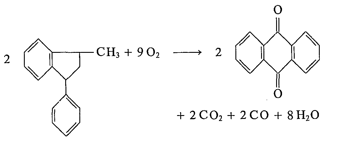
- Die als Ausgangsstoffe I verwendeten Indane lassen sich durch Dimerisierung von substituierten oder unsubstituierten Styrolen, z. B. nach den in vorgenannten Veröffentlichungen oder in Rabjohn, Organic Syntheses, Collective Volume IV (John Wiley Inc., New York 1963), Seiten 665 ff beschriebenen Verfahren herstellen. Bevorzugte Indane I und dementsprechend bevorzugte Anthrachinone der Formel

- Die Oxidation wird in der Regel mit einem Sauerstoffüberschuß durchgeführt. Bevorzugt ist ein Verhältnis von 15 bis 400 Mol Sauerstoff je Mol Indan I über die stöchiometrische Menge. In der Regel verwendet man Sauerstoff in Gestalt von Luft, ebenfalls können beliebige Gemische von Sauerstoff und unter den Reaktionsbedingungen inerten Gasen wie Argon, Wasserdampf, Stickstoff und/oder Kohlendioxid oder Rauchgas zur Anwendung gelangen. Bevorzugt, insbesondere im Falle des 1-Methyl-3-phenyl-indans, beträgt die Beladung 5 bis 100, vorteilhaft 10 bis 60, insbesondere 25 bis 55 Gramm Ausgangsstoff I pro ein Normalkubikmeter Luft. Im Falle der halogenierten 1-Methyl-3-phenyl- indane kann die Beladung bevorzugt 5 bis 100, vorteilhaft 20 bis 70, insbesondere 30 bis 60 Gramm Ausgangsstoff I pro ein Normalkubikmeter Luft betragen. Im kontinuierlichen Betrieb werden zweckmäßig von 20 bis 2000, vorzugsweise 40 bis 1000, vorteilhaft 60 bis 600 Gramm Ausgangsstoff I pro Liter Katalysator und Stunde oxidiert. Die gleichen Mengen Ausgangsstoff I, bezogen auf den Katalysator, werden in der Regel auch im diskontinuierlichen Betrieb verwendet.
- Die Oxidation wird in der Regel bei einer Temperatur zwischen 200 und 500°C, vorzugsweise zwischen 250 und 470° C, insbesondere zwischen 350 und 470° C, drucklos oder unter Druck, diskontinuierlich oder vorzugsweise kontinuierlich durchgeführt. Diese Temperatur wird in der Regel als Temperatur des Kühlmediums, z. B. eines Salpeterbades, gemessen (Rohrwandtemperatur). Man oxidiert z. B. den Ausgangsstoff I in der folgenden Weise: Das Ausgangsindan I wird verdampft und mit einem auf zweckmäßig 200 bis 400° C erhitzten Luftstrom vermischt. Es ist auch möglich, einen sauerstofffreien Teilstrom der Reaktionsabgase mit dem Dampf des Ausgangsstoffes zu sättigen und so die gewünschte Konzentration an Indan I im Reaktionsgemisch einzustellen. Das Gas-/Dampf-Gemisch wird dann in einem Reaktor bei der Reaktionstemperatur durch die Katalysatorschicht geleitet. Als Reaktoren kommen zweckmäßig mit einem Salzbad gekühlte Röhrenreaktoren, Wirbelschichtreaktoren mit eingebauten Kühlelementen oder Schichtreaktoren mit Zwischenkühlung in Frage. Aus dem Reaktionsgemisch wird nun in üblicher Weise der Endstoff abgetrennt, z. B. leitet man die den Reaktor verlassenden Gase durch einen oder mehrere Abscheider, um das Anthrachinon vom größten Teil der Nebenprodukte zu trennen. Gegebenenfalls ist eine Reinigung des Endstoffes möglich, indem man z. B. das Reaktionsgemisch in Wasser oder verdünnte Natronlauge leitet und aus dem dabei gebildeten festen Rückstand durch Sublimation den Endstoff isoliert oder den Endstoff in alkalischer Natriumdithionitlösung löst, den unumgesetzten Ausgangsstoff filtriert, anschließend aus dem Filtrat den Endstoff durch Luftoxidation ausfällt und abtrennt. Vorzugsweise trennt man nach dem in der deutschen Patentschrift 2 232 453 beschriebenen Verfahren das Anthrachinon aus dem Gemisch seines Dampfes mit einem reißen Trägergas ab, indem man das auf eine Temperatur von mindestens 200°C erhitzte Gemisch von Anthrachinondampf und Trägergas mit einer wäßrigen, gegebenenfalls ammoniakalischen Suspension von Anthrachinon unterhalb der Siedetemperatur des Wassers beim herrschenden Druck behandelt.
- Die erfindungsgemäß herstellbaren Anthrachinone sind wertvolle Ausgangsstoffe für die Herstellung von Farbstoffen und Schädlingsbekämpfungsmitteln. Bezüglich der Verwendung wird auf vorgenannte Veröffentlichungen und Ullmanns Encyklopädie der technischen Chemie, Band 3, Seiten 659 bis 732, verwiesen. Aus den Mono- und Dihalogenanthrachinonen können nach bekannten Verfahren durch Austausch der Halogenatome gegen Aminogruppen die entsprechenden Aminoanthrachinone erhalten werden, von denen sich, wie beispielsweise vom 1-Aminoanthrachinon, zahlreiche wertvolle Küpenfarbstoffe und lichtechte Lackpigmente ableiten.
- Die in dem folgenden Beispiel aufgeführten Teile bedeuten Gewichtsteile. Sie verhalten sich zu den Volumenteilen wie Gramm zu Milliliter.
-
- a) Ein Gemisch aus 451,9 Teilen Vanadinpentoxid, 50,3 Teilen Ammoniumvanadat (NH4V03), 8,0 Teilen Antimontrioxid und 0,98 Teilen Thalliumvanadat (TIV03) wird mit 1200 Teilen Wasser suspendiert. Die Suspension (20° C) wird mit einer Dosierpumpe zu einer Zweistoffdüse befördert, mit zugeführter Verdüsungsluft fein zerstäubt und auf die in einem rotierenden Beschichtungsteller (Winkel zur Horizontalen 47°, 15 Umdrehungen pro Minute) befindlichen Schüttung frei abrollender Trägerkugeln (Steatitkugeln von 6 Millimeter Durchmesser, Temperatur innerhalb der Schüttung 60°C) während 25 Minuten aufgesprüht. Der Drehteller ist zu 2/3 seines Volumens gefüllt. Die Geschwindigkeit des Auftrags beträgt 0,01 Teil Feststoff je Volumenteil Trägerkugeln und Minute. Das Wasser verdampft zum Teil während des Beschichtens. Anschließend wird noch 5 Minuten nachgetrocknet, bis die Temperatur innerhalb der Schüttung 105°C erreicht hat. Der fertige Katalysator enthält 0,15 Teile aktive Masse je Volumenteil Träger. Nun richtet man bei derselben Geschwindigkeit und Neigung des Drehtellers die Flamme eines Sauerstoff-Acetylen-Brenners während 5 Minuten mit 2700°C auf die Schüttung. Die Temperatur innerhalb der Schüttung beträgt 630° C, die Erhitzungstemperatur der Schüttungsoberfläche 750° C, die Aufheizzeit und Verweilzeit bei der Erhitzungstemperatur jedes kugelförmigen Schalenkatalysators beträgt pro Erhitzung zwischen 0,1 und 1 Sekunde, die Abkühlung pro Abkühlschritt und Schalenkatalysator beträgt 0,1 bis 1 Sekunde.
- b) 63,72 Teile des so hergestellten Katalysators werden in einen Röhrenreaktor (21 mm innerer Durchmesser) eingefüllt. Nun wird ein Gemisch von 200 000 Volumenteilen Luft und 7,6 Teilen 1-Methyl-3-phenylindan stündlich durch den Katalysator geleitet. Die Rohrwandtemperatur beträgt 420°C. Das den Reaktor verlassende, gasförmige Reaktionsgemisch wird auf 50'C abgekühlt, wobei der Endstoff und das nicht umgesetzte 1-Methyl-3-phenylindan kondensieren. Der nicht kondensierte Anteil wird mit Wasser gewaschen. Nach dem Abdampfen des Waschwassers wird der verbliebene Rückstand mit dem Kondensat vereinigt.
- Es werden nachstehende Ergebnisse erhalten:
- Ausgangsstoff 1-Methyl-3-phenyl-indan: 38,10 Teile
- Abgasmenge: 1 000 000 Volumenteile
- Gehalt des Abgases an Kohlenmonoxid
- und Kohlendioxid: 1,45 Volumen-%
- Roher Endstoff: 36,28 Teile
- Man erhält 74,1 Gewichtsprozent
- Anthrachinon 26,88 Teile
- 4,0 Teile Vanadinpentoxid werden unter Zugabe von 10,0 Teilen Oxalsäure in 200 Teilen Wasser gelöst, 96 Teile Titandioxid und 32 Teile Formamid zugesetzt und die gebildete Suspension auf Steatitkugeln von 5,4 mm Durchmesser (auf 300°C erhitzt) aufgetragen. Eine beschichtete Kugel enthält 4 Teile aktive Masse (Vanadinpentoxid und Titandioxid) und 96 Teile Träger. Die aktive Masse setzt sich aus 96 Gew.-% Titandioxid und 4 Gew.-% Vanadinpentoxid zusammen.
- 67 Teile des gemäß a) hergestellten Katalysators werden in einen Röhrenreaktor (21 mm innerer Rohrdurchmesser) eingefüllt. Nun wird ein Gemisch von 200 000 Volumenteilen Luft und 7,4 Teilen 1-Methyl-3-phenylindan stündlich durch den Katalysator geleitet. Die Rohrwandtemperatur beträgt 371°C. Das den Reaktor verlassende, gasförmige Reaktionsgemisch wird auf 50°C abgekühlt, wobei der Endstoff und das nicht umgesetzte 1-Methyl-3-phenylindan kondensieren. Der nicht kondensierte Anteil wird mit Wasser gewaschen. Nach dem Abdampfen des Waschwassers wird der verbliebene Rückstand mit dem Kondensat vereinigt.
- Es werden nachstehende Ergebnisse erhalten:
- Ausgangsstoff 1-Methyl-3-phenylindan: 22,22 Teile
- Abgasmenge: 600 000 Vol.-Teile
- Gehalt des Abgases an Kohlenmonoxid
- und -dioxid: 1,40 Vol.-%
- Roher Endstoff: 19,51 Teile
- In dem rohen Endstoff werden durch UV-Absorption bestimmt:
- 54,5 Gew.-% Anthrachinon 10,63 Teile
- 17 Gew.-% Phthalsäureanhydrid 3,3 Teile
- 2,2 Gew.-% nicht umgesetzter Ausgangsstoff 0,43 Teile
- 600 Teile Steatit-Ringe mit einem äußeren Durchmesser von 8 mm, einer Länge von 6 mm und einer Wandstärke von 1,5 mm werden in einer Dragiertrommel auf 260°C erhitzt und mit einer Suspension, bestehend aus 400 g Anatas, 31 Teilen Vanadinpentoxid, 500 Teilen Wasser, 100 Teilen Formamid, 0,89 Teilen Rubidiumcarbonat und 10,85 Teilen Antimontrioxid besprüht, bis das Gewicht der aufgetragenen katalytisch aktiven Masse 10% vom Gesamtgewicht des Katalysators ausmacht.
- Der Vanadinpentoxidgehalt des Trägerkatalysators beträgt 0,70 Gew. %.
- 42,6 Teile des gemäß Beispiel c) hergestellten Katalysators werden in einen Röhrenreaktor (21 mm innerer Rohrdurchmesser) eingefüllt. Nun wird ein Gemisch von 200 000 Volumenteilen Luft und 8,2 Teilen 1-Methyl-3-phenylindan stündlich durch den Katalysator geleitet. Die Rohrwandtemperatur beträgt 375° C. Das den Reaktor verlassende, gasförmige Reaktionsgemisch wird auf 50° C abgekühlt, wobei der Endstoff und das nicht umgesetzte 1-Methyl-3-phenylindan kondensieren. Der nicht kondensierte Anteil wird mit Wasser gewaschen. Nach dem Abdampfen des Waschwassers wird der verbliebene Rückstand mit dem Kondensat vereinigt.
- Es werden nachstehende Ergebnisse erhalten:
- Ausgangsstoff 1-Methyl-3-phenylindan 40,81 Teile
- Abgasmenge 1 000 000 Vol.-Teile
- Gehalt des Abgases an Kohlenmonoxid
- und -dioxid 2,43 Vol.-%
- Roher Endstoff 23,67 Teile
- In dem rohen Endstoff werden bestimmt:
- 72,0 Gew.-% Anthrachinonl 7,04 Teile
- (entspricht einer Anthrachinonausbeute, bezogen auf eingesetzten Ausgangsstoff von 41,8% der Theorie).
(entspricht einer Anthrachinonausbeute, bezogen auf eingesetzten Ausgangsstoff, von 70,6% der Theorie).
(entspricht einem Umsatz von 98,1% und einer Anthrachinonausbeute, bezogen auf umgesetzten Ausgangsstoff von 48,8% der Theorie).
Claims (2)

Applications Claiming Priority (2)
| Application Number | Priority Date | Filing Date | Title |
|---|---|---|---|
| DE2814262 | 1978-04-03 | ||
| DE19782814262 DE2814262A1 (de) | 1978-04-03 | 1978-04-03 | Schalenkatalysatoren und verfahren zu ihrer herstellung |
Publications (2)
| Publication Number | Publication Date |
|---|---|
| EP0004591A1 EP0004591A1 (de) | 1979-10-17 |
| EP0004591B1 true EP0004591B1 (de) | 1982-03-31 |
Family
ID=6036018
Family Applications (1)
| Application Number | Title | Priority Date | Filing Date |
|---|---|---|---|
| EP79100838A Expired EP0004591B1 (de) | 1978-04-03 | 1979-03-20 | Schalenkatalysatoren, Verfahren zu ihrer Herstellung und ihre Verwendung für die Bereitung von Anthrachinonen |
Country Status (5)
| Country | Link |
|---|---|
| US (1) | US4255285A (de) |
| EP (1) | EP0004591B1 (de) |
| JP (1) | JPS54133490A (de) |
| CA (1) | CA1134802A (de) |
| DE (2) | DE2814262A1 (de) |
Families Citing this family (17)
| Publication number | Priority date | Publication date | Assignee | Title |
|---|---|---|---|---|
| US4969989A (en) * | 1982-02-19 | 1990-11-13 | Union Oil Company Of California | Hydrocarbon conversion process with catalytic materials of controlled geometric mean electronegativity |
| US4816434A (en) * | 1982-02-19 | 1989-03-28 | Union Oil Company Of California | Catalytic materials of controlled geometric mean electronegativity |
| US4518710A (en) * | 1984-01-25 | 1985-05-21 | Uop Inc. | Catalyst for the reduction of nitrogen oxides in gaseous mixtures and method of making the catalyst |
| US4689316A (en) * | 1986-02-04 | 1987-08-25 | The Dow Chemical Company | Method of preparing supported catalysts |
| US4977126A (en) * | 1987-05-07 | 1990-12-11 | Exxon Research And Engineering Company | Process for the preparation of surface impregnated dispersed cobalt metal catalysts |
| US5545674A (en) * | 1987-05-07 | 1996-08-13 | Exxon Research And Engineering Company | Surface supported cobalt catalysts, process utilizing these catalysts for the preparation of hydrocarbons from synthesis gas and process for the preparation of said catalysts |
| US5194161A (en) * | 1989-09-25 | 1993-03-16 | Board Of Regents, The University Of Texas System | Materials and methods for enhanced photocatalyzation of organic compounds with palladium |
| US5256616A (en) * | 1989-09-25 | 1993-10-26 | Board Of Regents, The University Of Texas System | Materials and methods for photocatalyzing oxidation of organic compounds on water |
| DE4239876C1 (de) * | 1992-11-27 | 1994-07-28 | Degussa | Verfahren zur gleichmäßigen und reproduzierbaren Schalenimprägnierung von als Schüttgut vorliegenden Festbett-Katalysatorträgern und Vorrichtung zur Durchführung des Verfahrens |
| US5378673A (en) * | 1992-12-23 | 1995-01-03 | Exxon Research And Engineering Company | Method for atomically dispersing catalytic metals into support materials |
| US6281378B1 (en) * | 1995-06-08 | 2001-08-28 | Nippon Shokubai Co., Ltd. | Vanadium-containing catalysts, process for manufacturing and use of the same |
| DE19624923C1 (de) * | 1996-06-21 | 1998-03-12 | Siemens Ag | Verfahren zur Herstellung eines Katalysators sowie danach hergestellter Katalysator |
| US5854172A (en) * | 1997-01-17 | 1998-12-29 | The Standard Oil Company | Preparation of vanadium antimonate based catalysts using SnO2 ·xH2 O |
| DE19844758C1 (de) * | 1998-09-29 | 2000-07-06 | Siemens Ag | Verfahren zur Herstellung eines Katalysatorkörpers |
| US7775204B2 (en) * | 2007-01-05 | 2010-08-17 | Long Ho Chen | Warming shoe pad |
| DE102013006794A1 (de) | 2013-04-19 | 2014-10-23 | Thyssenkrupp Industrial Solutions Ag | Verfahren und Vorrichtung zur Herstellung von Schalenkatalysatoren |
| KR102727889B1 (ko) * | 2018-12-26 | 2024-11-07 | 현대자동차주식회사 | 연료 전지용 탄소 담지형 금속 촉매의 열처리 방법 및 이로부터 제조되는 탄소 담지형 금속 촉매 |
Family Cites Families (14)
| Publication number | Priority date | Publication date | Assignee | Title |
|---|---|---|---|---|
| DE1934063U (de) | 1964-07-23 | 1966-03-03 | Ritter Aluminium G M B H | Tragbuegelanordnung an milchkannen. |
| DE2028424C3 (de) | 1969-07-04 | 1974-05-30 | Basf Ag, 6700 Ludwigshafen | Verfahren zur Herstellung von Anthrachinon |
| DE2314695C2 (de) | 1973-03-24 | 1975-07-03 | Basf Ag, 6700 Ludwigshafen | Verfahren zur Herstellung von Anthrachinon |
| DE2050797C3 (de) | 1970-10-16 | 1975-07-03 | Basf Ag, 6700 Ludwigshafen | Verfahren zur Herstellung von Anthrachinon |
| DE2025430C3 (de) | 1970-05-25 | 1974-12-12 | Basf Ag, 6700 Ludwigshafen | Schalenkatalysatoren |
| DE2060215C3 (de) | 1970-12-08 | 1975-02-06 | Basf Ag, 6700 Ludwigshafen | Verfahren zur Herstellung von Anthrachinon |
| DE2122664C3 (de) | 1971-05-07 | 1975-03-20 | Basf Ag, 6700 Ludwigshafen | Verfahren zur Herstellung von Anthrachinon |
| US4151182A (en) * | 1971-05-24 | 1979-04-24 | Badische Anilin- & Soda-Fabrik Aktiengesellschaft | Production of anthraquinone |
| DE2135421A1 (de) | 1971-07-15 | 1973-01-25 | Basf Ag | Verfahren zur herstellung von anthrachinon |
| BE792486R (fr) * | 1971-12-08 | 1973-06-08 | Basf Ag | Procede de preparation |
| DE2224016C2 (de) | 1972-05-17 | 1974-03-28 | Dieter Haubold Industrielle Nagelgeraete, 3005 Hemmingen-Westerfeld | Auslösesicherung an einem Druckluftnagler |
| DE2232453C3 (de) | 1972-07-01 | 1975-07-24 | Basf Ag, 6700 Ludwigshafen | Verfahren zur Abtrennung von Anthrachinon aus dem Gemisch seines Dampfes mit einem Trägergas |
| DE2547655A1 (de) * | 1975-10-24 | 1977-04-28 | Basf Ag | Verfahren zur herstellung von halogensubstituierten anthrachinonen |
| DE2547624C2 (de) * | 1975-10-24 | 1981-10-08 | Basf Ag, 6700 Ludwigshafen | Vanadinpentoxid, Titandioxid, Antimon und Rubidium enthaltende Trägerkatalysatoren |
-
1978
- 1978-04-03 DE DE19782814262 patent/DE2814262A1/de active Pending
-
1979
- 1979-03-20 DE DE7979100838T patent/DE2962372D1/de not_active Expired
- 1979-03-20 EP EP79100838A patent/EP0004591B1/de not_active Expired
- 1979-03-21 CA CA000323920A patent/CA1134802A/en not_active Expired
- 1979-03-23 US US06/023,359 patent/US4255285A/en not_active Expired - Lifetime
- 1979-04-02 JP JP3846579A patent/JPS54133490A/ja active Pending
Also Published As
| Publication number | Publication date |
|---|---|
| EP0004591A1 (de) | 1979-10-17 |
| CA1134802A (en) | 1982-11-02 |
| US4255285A (en) | 1981-03-10 |
| DE2962372D1 (en) | 1982-05-06 |
| DE2814262A1 (de) | 1979-10-18 |
| JPS54133490A (en) | 1979-10-17 |
Similar Documents
| Publication | Publication Date | Title |
|---|---|---|
| EP0004591B1 (de) | Schalenkatalysatoren, Verfahren zu ihrer Herstellung und ihre Verwendung für die Bereitung von Anthrachinonen | |
| EP0744214B1 (de) | Trägerkatalysator für Gasphasenoxidationsreaktionen | |
| EP0015569B1 (de) | Verfahren zur Herstellung von Schalenkatalysatoren | |
| DE2948163C2 (de) | Katalysator zur Herstellung von Phthalsäureanhydrid | |
| DE2025430C3 (de) | Schalenkatalysatoren | |
| EP2435395A2 (de) | Katalysator und verfahren zur partialoxidation von kohlenwasserstoffen | |
| EP0966324A1 (de) | Verfahren zur herstellung von schalenkatalysatoren für die katalytische gasphasenoxidation von aromatischen kohlenwasserstoffen | |
| DE69207552T2 (de) | Verfahren zur Herstellung von Phthalsäureanhydrid durch Oxydation der Gemisch von ortho-Xylol mit Naphthalin | |
| EP0951351A1 (de) | Verwendung eines schalenkatalysators zur herstellung von essigsäure durch gasphasenoxidation von ungesättigten c 4-kohlenwasserstoffen | |
| EP1670582A1 (de) | Verfahren zur herstellung eines katalysators für gasphasenoxidationen durch beschichten von trägermaterial in einer fliessbettapparatur | |
| DE3410799C2 (de) | ||
| EP1670741B1 (de) | Verfahren zur herstellung eines gasphasenoxidationskatalysators mit definierter vanadiumoxid-teilchengrössenverteilung | |
| EP2125213A1 (de) | Aus hohlen formen bestehende mischoxidkatalysatoren | |
| WO2002081421A1 (de) | Verfahren zur herstellung von acrylsäure oder methacrylsäure durch gasphasenoxidation von propan oder isobutan | |
| DE2321799A1 (de) | Katalysatormischung zur oxidation von o-xylol oder naphthalin zu phthalsaeureanhydrid | |
| DE10359027A1 (de) | Verfahren zur Herstellung einer Multimetalloxidmasse | |
| DE2547655A1 (de) | Verfahren zur herstellung von halogensubstituierten anthrachinonen | |
| EP1909957A1 (de) | Schalenkatalysator, seine herstellung und seine verwendung in einem ammonoxidationsverfahren | |
| DE2550686A1 (de) | Verfahren zur herstellung eines katalysators | |
| DE2129790A1 (de) | Katalysatorzusammensetzung fuer die Oxydation von o-Xylol zu Phthalsaeureanhydrid | |
| WO2001085337A1 (de) | Silber, vanadium und ein oder mehrere elemente der phosphorgruppe enthaltendes multimetalloxid und dessen verwendung | |
| WO2016177764A1 (de) | Verfahren zur herstellung chrom enthaltender katalysatoren für die oxidehydrierung von n-butenen zu butadien unter vermeidung von cr(vi)-intermediaten | |
| DE2008648C3 (de) | Metalloxydkatalysator | |
| DE19633757A1 (de) | Trägerkatalysator zur Herstellung von Phthalsäureanhydrid | |
| CH419067A (de) | Katalysator |
Legal Events
| Date | Code | Title | Description |
|---|---|---|---|
| PUAI | Public reference made under article 153(3) epc to a published international application that has entered the european phase |
Free format text: ORIGINAL CODE: 0009012 |
|
| AK | Designated contracting states |
Designated state(s): BE DE FR GB IT NL |
|
| 17P | Request for examination filed | ||
| ITF | It: translation for a ep patent filed | ||
| GRAA | (expected) grant |
Free format text: ORIGINAL CODE: 0009210 |
|
| AK | Designated contracting states |
Designated state(s): BE DE FR GB IT NL |
|
| REF | Corresponds to: |
Ref document number: 2962372 Country of ref document: DE Date of ref document: 19820506 |
|
| PGFP | Annual fee paid to national office [announced via postgrant information from national office to epo] |
Ref country code: DE Payment date: 19830223 Year of fee payment: 5 |
|
| PGFP | Annual fee paid to national office [announced via postgrant information from national office to epo] |
Ref country code: FR Payment date: 19830225 Year of fee payment: 5 |
|
| PGFP | Annual fee paid to national office [announced via postgrant information from national office to epo] |
Ref country code: NL Payment date: 19830331 Year of fee payment: 5 Ref country code: BE Payment date: 19830331 Year of fee payment: 5 |
|
| PG25 | Lapsed in a contracting state [announced via postgrant information from national office to epo] |
Ref country code: DE Effective date: 19840215 |
|
| PG25 | Lapsed in a contracting state [announced via postgrant information from national office to epo] |
Ref country code: BE Effective date: 19840331 |
|
| BERE | Be: lapsed |
Owner name: BASF A.G. Effective date: 19840320 |
|
| PG25 | Lapsed in a contracting state [announced via postgrant information from national office to epo] |
Ref country code: NL Effective date: 19841001 |
|
| GBPC | Gb: european patent ceased through non-payment of renewal fee | ||
| NLV4 | Nl: lapsed or anulled due to non-payment of the annual fee | ||
| GBPC | Gb: european patent ceased through non-payment of renewal fee | ||
| PG25 | Lapsed in a contracting state [announced via postgrant information from national office to epo] |
Ref country code: FR Free format text: LAPSE BECAUSE OF NON-PAYMENT OF DUE FEES Effective date: 19841130 |
|
| REG | Reference to a national code |
Ref country code: FR Ref legal event code: ST |
|
| PG25 | Lapsed in a contracting state [announced via postgrant information from national office to epo] |
Ref country code: GB Effective date: 19881117 |
|
| PLBE | No opposition filed within time limit |
Free format text: ORIGINAL CODE: 0009261 |
|
| STAA | Information on the status of an ep patent application or granted ep patent |
Free format text: STATUS: NO OPPOSITION FILED WITHIN TIME LIMIT |