EP0004281B2 - Verfahren zum Regeln des Füllungsgrades eines Speichers in einer Fördereinrichtung eines Extruders und Vorrichtung zum Durchführen dieses Verfahrens - Google Patents
Verfahren zum Regeln des Füllungsgrades eines Speichers in einer Fördereinrichtung eines Extruders und Vorrichtung zum Durchführen dieses Verfahrens Download PDFInfo
- Publication number
- EP0004281B2 EP0004281B2 EP79100465A EP79100465A EP0004281B2 EP 0004281 B2 EP0004281 B2 EP 0004281B2 EP 79100465 A EP79100465 A EP 79100465A EP 79100465 A EP79100465 A EP 79100465A EP 0004281 B2 EP0004281 B2 EP 0004281B2
- Authority
- EP
- European Patent Office
- Prior art keywords
- signal
- filling
- reservoir
- output
- volume
- Prior art date
- Legal status (The legal status is an assumption and is not a legal conclusion. Google has not performed a legal analysis and makes no representation as to the accuracy of the status listed.)
- Expired
Links
Images

Classifications
-
- B—PERFORMING OPERATIONS; TRANSPORTING
- B29—WORKING OF PLASTICS; WORKING OF SUBSTANCES IN A PLASTIC STATE IN GENERAL
- B29C—SHAPING OR JOINING OF PLASTICS; SHAPING OF MATERIAL IN A PLASTIC STATE, NOT OTHERWISE PROVIDED FOR; AFTER-TREATMENT OF THE SHAPED PRODUCTS, e.g. REPAIRING
- B29C48/00—Extrusion moulding, i.e. expressing the moulding material through a die or nozzle which imparts the desired form; Apparatus therefor
- B29C48/25—Component parts, details or accessories; Auxiliary operations
- B29C48/36—Means for plasticising or homogenising the moulding material or forcing it through the nozzle or die
- B29C48/475—Means for plasticising or homogenising the moulding material or forcing it through the nozzle or die using pistons, accumulators or press rams
-
- B—PERFORMING OPERATIONS; TRANSPORTING
- B29—WORKING OF PLASTICS; WORKING OF SUBSTANCES IN A PLASTIC STATE IN GENERAL
- B29C—SHAPING OR JOINING OF PLASTICS; SHAPING OF MATERIAL IN A PLASTIC STATE, NOT OTHERWISE PROVIDED FOR; AFTER-TREATMENT OF THE SHAPED PRODUCTS, e.g. REPAIRING
- B29C48/00—Extrusion moulding, i.e. expressing the moulding material through a die or nozzle which imparts the desired form; Apparatus therefor
- B29C48/25—Component parts, details or accessories; Auxiliary operations
- B29C48/30—Extrusion nozzles or dies
- B29C48/32—Extrusion nozzles or dies with annular openings, e.g. for forming tubular articles
-
- B—PERFORMING OPERATIONS; TRANSPORTING
- B29—WORKING OF PLASTICS; WORKING OF SUBSTANCES IN A PLASTIC STATE IN GENERAL
- B29C—SHAPING OR JOINING OF PLASTICS; SHAPING OF MATERIAL IN A PLASTIC STATE, NOT OTHERWISE PROVIDED FOR; AFTER-TREATMENT OF THE SHAPED PRODUCTS, e.g. REPAIRING
- B29C48/00—Extrusion moulding, i.e. expressing the moulding material through a die or nozzle which imparts the desired form; Apparatus therefor
- B29C48/25—Component parts, details or accessories; Auxiliary operations
- B29C48/36—Means for plasticising or homogenising the moulding material or forcing it through the nozzle or die
- B29C48/375—Plasticisers, homogenisers or feeders comprising two or more stages
- B29C48/388—Plasticisers, homogenisers or feeders comprising two or more stages using a screw extruder and a ram or piston
-
- B—PERFORMING OPERATIONS; TRANSPORTING
- B29—WORKING OF PLASTICS; WORKING OF SUBSTANCES IN A PLASTIC STATE IN GENERAL
- B29C—SHAPING OR JOINING OF PLASTICS; SHAPING OF MATERIAL IN A PLASTIC STATE, NOT OTHERWISE PROVIDED FOR; AFTER-TREATMENT OF THE SHAPED PRODUCTS, e.g. REPAIRING
- B29C48/00—Extrusion moulding, i.e. expressing the moulding material through a die or nozzle which imparts the desired form; Apparatus therefor
- B29C48/25—Component parts, details or accessories; Auxiliary operations
- B29C48/92—Measuring, controlling or regulating
-
- B—PERFORMING OPERATIONS; TRANSPORTING
- B29—WORKING OF PLASTICS; WORKING OF SUBSTANCES IN A PLASTIC STATE IN GENERAL
- B29C—SHAPING OR JOINING OF PLASTICS; SHAPING OF MATERIAL IN A PLASTIC STATE, NOT OTHERWISE PROVIDED FOR; AFTER-TREATMENT OF THE SHAPED PRODUCTS, e.g. REPAIRING
- B29C2948/00—Indexing scheme relating to extrusion moulding
- B29C2948/92—Measuring, controlling or regulating
- B29C2948/92009—Measured parameter
- B29C2948/92085—Velocity
- B29C2948/92095—Angular velocity
-
- B—PERFORMING OPERATIONS; TRANSPORTING
- B29—WORKING OF PLASTICS; WORKING OF SUBSTANCES IN A PLASTIC STATE IN GENERAL
- B29C—SHAPING OR JOINING OF PLASTICS; SHAPING OF MATERIAL IN A PLASTIC STATE, NOT OTHERWISE PROVIDED FOR; AFTER-TREATMENT OF THE SHAPED PRODUCTS, e.g. REPAIRING
- B29C2948/00—Indexing scheme relating to extrusion moulding
- B29C2948/92—Measuring, controlling or regulating
- B29C2948/92009—Measured parameter
- B29C2948/92114—Dimensions
- B29C2948/92161—Volume or quantity
-
- B—PERFORMING OPERATIONS; TRANSPORTING
- B29—WORKING OF PLASTICS; WORKING OF SUBSTANCES IN A PLASTIC STATE IN GENERAL
- B29C—SHAPING OR JOINING OF PLASTICS; SHAPING OF MATERIAL IN A PLASTIC STATE, NOT OTHERWISE PROVIDED FOR; AFTER-TREATMENT OF THE SHAPED PRODUCTS, e.g. REPAIRING
- B29C2948/00—Indexing scheme relating to extrusion moulding
- B29C2948/92—Measuring, controlling or regulating
- B29C2948/92504—Controlled parameter
- B29C2948/92609—Dimensions
- B29C2948/92657—Volume or quantity
-
- B—PERFORMING OPERATIONS; TRANSPORTING
- B29—WORKING OF PLASTICS; WORKING OF SUBSTANCES IN A PLASTIC STATE IN GENERAL
- B29C—SHAPING OR JOINING OF PLASTICS; SHAPING OF MATERIAL IN A PLASTIC STATE, NOT OTHERWISE PROVIDED FOR; AFTER-TREATMENT OF THE SHAPED PRODUCTS, e.g. REPAIRING
- B29C2948/00—Indexing scheme relating to extrusion moulding
- B29C2948/92—Measuring, controlling or regulating
- B29C2948/92819—Location or phase of control
- B29C2948/92828—Raw material handling or dosing, e.g. active hopper or feeding device
-
- B—PERFORMING OPERATIONS; TRANSPORTING
- B29—WORKING OF PLASTICS; WORKING OF SUBSTANCES IN A PLASTIC STATE IN GENERAL
- B29C—SHAPING OR JOINING OF PLASTICS; SHAPING OF MATERIAL IN A PLASTIC STATE, NOT OTHERWISE PROVIDED FOR; AFTER-TREATMENT OF THE SHAPED PRODUCTS, e.g. REPAIRING
- B29C2948/00—Indexing scheme relating to extrusion moulding
- B29C2948/92—Measuring, controlling or regulating
- B29C2948/92819—Location or phase of control
- B29C2948/92857—Extrusion unit
- B29C2948/92876—Feeding, melting, plasticising or pumping zones, e.g. the melt itself
- B29C2948/92885—Screw or gear
-
- B—PERFORMING OPERATIONS; TRANSPORTING
- B29—WORKING OF PLASTICS; WORKING OF SUBSTANCES IN A PLASTIC STATE IN GENERAL
- B29C—SHAPING OR JOINING OF PLASTICS; SHAPING OF MATERIAL IN A PLASTIC STATE, NOT OTHERWISE PROVIDED FOR; AFTER-TREATMENT OF THE SHAPED PRODUCTS, e.g. REPAIRING
- B29C48/00—Extrusion moulding, i.e. expressing the moulding material through a die or nozzle which imparts the desired form; Apparatus therefor
- B29C48/03—Extrusion moulding, i.e. expressing the moulding material through a die or nozzle which imparts the desired form; Apparatus therefor characterised by the shape of the extruded material at extrusion
- B29C48/09—Articles with cross-sections having partially or fully enclosed cavities, e.g. pipes or channels
- B29C48/10—Articles with cross-sections having partially or fully enclosed cavities, e.g. pipes or channels flexible, e.g. blown foils
-
- B—PERFORMING OPERATIONS; TRANSPORTING
- B29—WORKING OF PLASTICS; WORKING OF SUBSTANCES IN A PLASTIC STATE IN GENERAL
- B29C—SHAPING OR JOINING OF PLASTICS; SHAPING OF MATERIAL IN A PLASTIC STATE, NOT OTHERWISE PROVIDED FOR; AFTER-TREATMENT OF THE SHAPED PRODUCTS, e.g. REPAIRING
- B29C48/00—Extrusion moulding, i.e. expressing the moulding material through a die or nozzle which imparts the desired form; Apparatus therefor
- B29C48/03—Extrusion moulding, i.e. expressing the moulding material through a die or nozzle which imparts the desired form; Apparatus therefor characterised by the shape of the extruded material at extrusion
- B29C48/13—Articles with a cross-section varying in the longitudinal direction, e.g. corrugated pipes
Definitions
- the invention relates to a method for regulating the degree of filling of a store in a conveyor of an extruder according to the preamble of claim 1, and to a device for performing the method.
- a cylindrical preform is first formed in an extruder, which is then brought to the desired outside diameter in a blow mold in a subsequent operation.
- a conveyor device is provided in the extruder, which conveys the material for the blow molding in a store, from which a specific volume for the blow mold can be removed during each working cycle.
- the delivery rate of the conveyor must be set so that the required amount of material is fed into the memory in the time available. Deviations in the delivery rate from the required delivery rate lead to disadvantages.
- the degree of filling of the memory is queried. If a deviation from a predetermined degree of filling is determined, the delivery rate of the conveyor is increased or decreased accordingly by increasing or decreasing the speed of the conveyor.
- a cylinder serves as a material store.
- a piston arranged in the cylinder is pushed back by the conveyed material.
- the position of the piston and thus the degree of filling at the beginning of an ejection cycle depends on the speed of the conveyor.
- the speed is regulated according to the determined degree of filling.
- This regulation then leads to disadvantageous vibrations, i. that is, the start and end points of the piston stroke travel fluctuate by an average value if the discharge volume per cycle is kept constant. This affects the proper functioning of the machine, especially with large flow rates.
- the invention is based on the object of specifying a method for regulating the degree of filling of a store in a conveying device of an extruder of the type mentioned at the outset, which works without oscillation effects.
- the method according to the invention provides, in contrast, to also process the actual fill volume of the store as a controlled variable.
- the actual filling level is derived from the end position of the piston before ejection begins, the filling volume, however, results from the return path of the piston when the reservoir is refilled and the piston cross-section.
- the method according to the invention prevents the arrangement from vibrating, thereby ensuring that the extruder functions properly.
- the sum signal consists of a voltage
- this voltage is converted into a correspondingly long time interval.
- the speed of the conveyor is adjusted during this time interval.
- the speed is accordingly set in proportion to the amplitude of the sum signal. This ensures quick and precise control.
- a preferred development of the invention is specified in claim 3. This measure ensures that there are no mold waiting times because the minimum filling level of the memory is certainly reached when the mold is ready to receive material.
- the method specified in claim 4 enables a simple start-up of the extruder.
- the «AND» link between the two conditions «form readiness» and «minimum degree of filling achieved» means that the mold can be made available when the machine starts up, regardless of the degree of filling of the storage.
- a device for performing the method according to the invention is specified in claim 5. Only relatively few components are required in the device according to the invention.
- the position transmitter required to obtain the signals for the actual filling level and the filling volume is usually in question with the coming extruders already available; it is used, for example, to generate control signals that are required in the molding process.
- the transducer for generating the storage volume signal can be, for example, an integrator which integrates a signal corresponding to the path of the ejection piston when the storage is being filled.
- the device according to the invention can easily be installed in existing extruders.
- the extruder shown in Fig. 1 contains a tool head 1 with a movable mandrel 2, which in the tool head 1, depending on its axial position, forms a cross-sectionally variable outlet opening 3 through which a plasticized, extrudable material can be pressed to form a preform 4 .
- This preform 4 is then molded into the desired product, for example a bottle, in a blow mold (not shown).
- a plasticizing device 5 is provided with a heated chamber 6, into which a material granulate can be introduced via a feed hopper 7.
- a rotatable screw conveyor 8 which presses the material plasticized by the action of heat into a channel 9.
- the channel 9 opens into a storage cylinder 11, in which a piston 12 is slidably arranged.
- the z. B. is formed by a potentiometer with which the respective axial position of the piston 12 can be reproduced by an electrical signal.
- the screw conveyor 8 is rotated by a drive motor 15.
- a speed controller 16 is connected to the drive motor 15, by means of which the speed of the drive motor 15 can be changed.
- the extruder works as follows.
- the drive motor 15 rotates the screw conveyor 8 at a speed which depends on the voltage supplied to it. This voltage is determined by the speed controller.
- the speed controller determines the speed at which the piston 12 is in its right position shortly before the constriction of the accumulator 11 after an ejection process.
- the outlet opening 3 is closed.
- the material 9 is pressed into the accumulator 11 through the channel 9, causing the piston 12 to follow with the piston rod 13 is pushed to the left.
- a storage filling volume signal is generated via the position transmitter and a measuring transducer, not shown, which represents the actual filling volume.
- a signal representative of the actual filling level of the memory can be tapped directly from the position transmitter.
- this signal reaches a predetermined value and the mold (not shown) is ready for the material intake, the piston 12 is pushed to the right by a pushing device, not shown, while the outlet opening 3 is opened at the same time.
- the values of the filling volume and the actual filling level are fed to the speed controller 16 in order to be further processed there.
- a control signal obtained in this way is used to change the voltage supplied to the drive motor 15, if necessary, in order to vary the material throughput through the channel 9, which adjoins the screw conveyor.
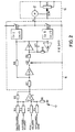
- the signals for the actual filling level and the respective actual filling volume of the memory are arithmetically linked to the preset values for the desired filling level and the discharge volume, which also has a predetermined value according to a predetermined size of the piston stroke Obtain sum signal S according to the following formula:
- the speed controller 16 comprises a summing device consisting of an operational amplifier A1 and resistors R1-R6. Two resistors R1 and R2 are connected to the minus input of operational amplifier A1. The output of operational amplifier A1 is connected to the minus input via a resistor R5. The resistor R1 is acted upon by a signal representative of the target filling level. This can be tapped, for example, by a potentiometer. A signal for the discharge volume, which is fed to the resistor R2, can also be generated by a potentiometer. Two resistors R3 and R4 are connected to the plus input of operational amplifier A1. Furthermore, the plus input is connected to ground via a resistor R6. The above-mentioned signal for the filling volume is fed to the resistor R3, while the signal representative of the actual filling level of the memory is fed to the resistor R4 receive the sum signal S at its output in accordance with the above equation.
- a resistor R7 is in series with an operational amplifier A2, a switch Si, a resistor R9 and an operational amplifier A3.
- an operational amplifier A3 With the output of the operational amplifier A3 is the input of an operator amplifier A4 connected, the output of which in turn is connected via a resistor R10 to the input of operational amplifier A4.
- a capacitor C1 is connected in parallel with the operational amplifier A4 and the resistor R10.
- the output of the operational amplifier A3 is connected to the respective input of a first comparator CO I and a second comparator CO II. Furthermore, the output of the operational amplifier A3 is connected via the resistor R8 to the connecting line of the resistor R7 and the operational amplifier A2.
- the size of the resistor R10 is much larger than the resistor R9.
- the reference voltage of the comparator CO I is positive (Ug> 0), while the reference voltage of the comparator CO II has the same amount, but has a negative sign (U s ⁇ 0).
- the output signals of the comparators CO I and CO II each control a switch S2 or S3, of which the two switch contacts of the one switch S2 are connected to a positive voltage source or the output A of the converter 18 and the two switch contacts of the other switch S3 are between one negative voltage source and the mentioned output A are connected. If the switch S2 is closed by an output signal of the comparator CO I, a positive potential is thus supplied to the output A of the converter 18, while a negative potential is supplied to the output A by closing the switch S3.
- the switches S2 and S3 are preferably relays, while the switch S1 is preferably designed as a field effect transistor.
- the input A of a servo control device 19 is connected to the output A of the converter 18.
- the latter comprises a motor M which moves a wiper SCH of a potentiometer R11 in one direction or the other when positive or negative potential is supplied to it.
- the voltage tapped at the potentiometer R11 is fed to the drive motor 15.
- Fig. 2 operates as follows. At the output of the summing device, i.e. H. At the output of the operational amplifier A1, a sum signal S is generated according to the above equation. At the beginning of an ejection process, switch S1 is closed for approx. 10 ms. The signal to close switch S1 is obtained by ANDing the signals «Form ready and « Minimum fill level of the memory reached •. This can, for. B. when starting the machine, the shape can be brought into preparation without the memory already having to be filled. Closing switch S1 has the result that control loop A1, Si, R9, A3, R8 is closed. As a result, a voltage proportional to the sum signal is established at the output of A3.
- the motor moves the grinder SCH of the potentiometer R11, as a result of which the speed of the motor drive 15 is reduced in this case.
- the switch S2 is closed for a certain period of time, which results in an increase in the engine speed.
- the discharge of the capacitor C1 takes longer, the greater the amount of the sum signal S.
- the relevant switch S2 or S3 is closed for a more or less long time.
- the converter 18 thus causes the motor M of the servo control device 19 to be supplied with a potential for a certain period of time.
- the time period depends on the amplitude of the sum signal S.
- the sign of the sum signal S determines the direction in which the motor M is rotated, i. H. whether the speed of the drive motor 15 and thus the screw conveyor 8 is increased or decreased.
- the response sensitivity of the control device can be set by selecting the reference voltage U s of the two comparators.
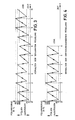
- the value of the target fill level supplied to the summing device is set so that it is approximately 105% of the minimum fill level of the memory. If the storage tank is filled up to the minimum filling level, the stored volume corresponds exactly to the output volume. The addition of 5% ensures that there is always enough material in the memory 11 before each ejection process.
- the speed of the conveying device has been set correctly, and that the accumulator is filled up to the target filling level of, for example, 105% and ejected to 5% (see FIGS. 3 and 4).
- the difference between the actual filling level and the target filling level is zero, so that the known method does not correct the speed. Since the difference between the filling volume and the discharge volume is also zero, the sum signal S also becomes zero in the method according to the invention, so that the speed of rotation also here is not corrected.
- the speed is increased again by approx. 5%.
- the sum signal is:
- the speed of the conveyor is therefore increased by approx. 5%.
Landscapes
- Engineering & Computer Science (AREA)
- Mechanical Engineering (AREA)
- Manufacturing & Machinery (AREA)
- Blow-Moulding Or Thermoforming Of Plastics Or The Like (AREA)
- Extrusion Moulding Of Plastics Or The Like (AREA)
- Processing And Handling Of Plastics And Other Materials For Molding In General (AREA)
- Basic Packing Technique (AREA)
- Control Of Conveyors (AREA)
Applications Claiming Priority (2)
| Application Number | Priority Date | Filing Date | Title |
|---|---|---|---|
| DE2813241A DE2813241C2 (de) | 1978-03-28 | 1978-03-28 | Verfahren zum Regeln des Füllungsgrades eines Speichers in einer Fördereinrichtung eines Extruders und Vorrichtung zum Durchführen dieses Verfahrens |
| DE2813241 | 1978-03-28 |
Publications (4)
| Publication Number | Publication Date |
|---|---|
| EP0004281A2 EP0004281A2 (de) | 1979-10-03 |
| EP0004281A3 EP0004281A3 (en) | 1979-10-31 |
| EP0004281B1 EP0004281B1 (de) | 1981-03-04 |
| EP0004281B2 true EP0004281B2 (de) | 1984-04-11 |
Family
ID=6035532
Family Applications (1)
| Application Number | Title | Priority Date | Filing Date |
|---|---|---|---|
| EP79100465A Expired EP0004281B2 (de) | 1978-03-28 | 1979-02-16 | Verfahren zum Regeln des Füllungsgrades eines Speichers in einer Fördereinrichtung eines Extruders und Vorrichtung zum Durchführen dieses Verfahrens |
Country Status (4)
| Country | Link |
|---|---|
| US (1) | US4224561A (enExample) |
| EP (1) | EP0004281B2 (enExample) |
| JP (1) | JPS54127966A (enExample) |
| DE (1) | DE2813241C2 (enExample) |
Families Citing this family (13)
| Publication number | Priority date | Publication date | Assignee | Title |
|---|---|---|---|---|
| DE2940904A1 (de) * | 1979-10-09 | 1981-04-23 | Moog GmbH, 7030 Böblingen | Verfahren und vorrichtung zum regeln der foerderleistung eines extruders |
| CH655793A5 (de) * | 1982-02-01 | 1986-05-15 | Maag Zahnraeder & Maschinen Ag | Profilmesssteuereinrichtung. |
| DE3414444A1 (de) * | 1984-04-17 | 1985-10-17 | Continental Gummi-Werke Ag, 3000 Hannover | Strangpresse |
| DE3416552C2 (de) * | 1984-05-04 | 1994-05-19 | Recycloplast Ag | Verfahren und Vorrichtung zum Aufteilen eines plastifizierten, aus einer Mündung austretenden Kunststoffstrangs |
| DE3809857A1 (de) * | 1988-03-24 | 1989-10-05 | Philips Patentverwaltung | Blasformmaschine zum blasformen von hohlkoerpern mit polsterregelung |
| DE3809856A1 (de) * | 1988-03-24 | 1989-10-05 | Philips Patentverwaltung | Blasformmaschine zum blasformen von hohlkoerpern mit wartezeitregelung |
| JPH0539858Y2 (enExample) * | 1988-04-11 | 1993-10-08 | ||
| DE3936301A1 (de) * | 1989-11-01 | 1991-05-02 | Kautex Maschinenbau Gmbh | Verfahren zum herstellen von hohlkoerpern aus thermoplastischen kunststoff |
| JPH03274134A (ja) * | 1990-03-26 | 1991-12-05 | Ube Ind Ltd | ダイスへの樹脂供給装置 |
| JP4086916B2 (ja) * | 1996-07-08 | 2008-05-14 | 九州日立マクセル株式会社 | 電気バリカン |
| JP5889115B2 (ja) * | 2012-06-06 | 2016-03-22 | オリンパス株式会社 | 混練押出成形装置 |
| DE102012112110A1 (de) * | 2012-12-11 | 2014-06-12 | Kautex Maschinenbau Gmbh | Extrusionsblasformverfahren und Vorrichtung zu dessen Durchführung |
| DE102018209998B4 (de) * | 2018-06-20 | 2021-09-02 | Universität Stuttgart | Verfahren und Vorrichtung zur Untersuchung eines thermoplastischen Werkstoffs |
Family Cites Families (9)
| Publication number | Priority date | Publication date | Assignee | Title |
|---|---|---|---|---|
| DE1813421C3 (de) * | 1968-12-07 | 1974-12-12 | Indramat, Gesellschaft Fuer Industrierationalisierung Und Automatisierung Mbh, 8770 Lohr | Vorrichtung zum Steuern der Wandstärke des Kunststoffstranges eines Extruders |
| US3693946A (en) * | 1971-05-10 | 1972-09-26 | Cincinnati Milacron Inc | Plastication control for injection molding machines |
| JPS4953657A (enExample) * | 1972-09-25 | 1974-05-24 | ||
| DE2300171A1 (de) * | 1973-01-03 | 1974-07-11 | Bucher Guyer Ag Masch | Verfahren zum regeln der aushaertzeit der kunststoffmasse in der form einer spritzgiessmaschine |
| JPS5344921B2 (enExample) * | 1973-07-19 | 1978-12-02 | ||
| US3865528A (en) * | 1973-11-01 | 1975-02-11 | Moog Inc | Extrusion apparatus having electronic interpolator |
| JPS5627132B2 (enExample) * | 1974-11-27 | 1981-06-23 | ||
| DE2544609C3 (de) * | 1975-10-06 | 1984-11-08 | Kautex Werke Reinold Hagen Gmbh, 5300 Bonn | Einrichtung zum Beeinflussen der Länge eines Vorformlings aus thermoplastischem Kunststoff |
| JPS5374569A (en) * | 1976-12-15 | 1978-07-03 | Kayaba Industry Co Ltd | Apparatus for compensating length of parison in hollow plastic molding machine |
-
1978
- 1978-03-28 DE DE2813241A patent/DE2813241C2/de not_active Expired
-
1979
- 1979-02-16 EP EP79100465A patent/EP0004281B2/de not_active Expired
- 1979-03-09 JP JP2757979A patent/JPS54127966A/ja active Granted
- 1979-03-16 US US06/021,151 patent/US4224561A/en not_active Expired - Lifetime
Also Published As
| Publication number | Publication date |
|---|---|
| JPS54127966A (en) | 1979-10-04 |
| EP0004281A2 (de) | 1979-10-03 |
| US4224561A (en) | 1980-09-23 |
| DE2813241B1 (de) | 1979-10-04 |
| EP0004281A3 (en) | 1979-10-31 |
| JPS6258282B2 (enExample) | 1987-12-04 |
| EP0004281B1 (de) | 1981-03-04 |
| DE2813241C2 (de) | 1984-08-30 |
Similar Documents
| Publication | Publication Date | Title |
|---|---|---|
| EP0004281B2 (de) | Verfahren zum Regeln des Füllungsgrades eines Speichers in einer Fördereinrichtung eines Extruders und Vorrichtung zum Durchführen dieses Verfahrens | |
| DE2253506C3 (de) | Regeleinrichtung für die Einspritzeinheit einer Schnecken-Spritzgießmaschine | |
| EP1929253B1 (de) | Verfahren zur steuerung einer dosiereinrichtung für flüssige oder pasteuse medien | |
| DE2210854A1 (de) | Regelsystem fuer spritzgussmaschine | |
| DE2836692A1 (de) | Verfahren und vorrichtung zur verringerung der auf austrieben an den teilfugen von spritzgussformen beruhenden beschaedigungsgefahr | |
| DE3021978C2 (enExample) | ||
| EP0185984B1 (de) | Hydraulikeinrichtung für die Spritzgiesseinheit einer Kunststoff-Spritzgiessmaschine | |
| DE10135345B4 (de) | Elektrische Spritzgussmaschine und Verfahren zum Steuern einer elektrischen Spritzgussmaschine | |
| DE2417986A1 (de) | Dynamische druckregelvorrichtung | |
| DE69113869T2 (de) | Spritzgiesssteuerung mit prozessvariablem Lernverfahren. | |
| EP3870422B1 (de) | Verfahren zum betreiben einer spritzgiessmaschine, insbesondere hinsichtlich verbesserter konstanter werkzeugfüllung, sowie spritzgiessmaschine zur durchführung des verfahrens | |
| DE69617974T2 (de) | Kombinationssteuerung für das spritzgiessen | |
| EP0707936B1 (de) | Verfahren zur Bestimmung des Umschaltpunktes bei der Herstellung eines Spritzgussteils | |
| DE4002398C2 (de) | Vorrichtung zum Steuern der Einregelung der Gießbedingungen einer Spritzgießmaschine | |
| DE3809792A1 (de) | Verfahren und vorrichtung zum spritzgiessen | |
| DE19514070A1 (de) | Steuerverfahren für eine Spritzgußvorrichtung | |
| DE102007012199A1 (de) | Verfahren zum Betreiben einer Plastifizierungseinrichtung, z. B. eines Extruders oder einer Spritzgussmaschine | |
| DE69305837T2 (de) | Verbesserungen in Bezug auf hydraulischbetätigte Kolben-Strangpressen | |
| DE2920559C2 (de) | Verfahren und Anordnung zur Regelung der Extrusionsgeschwindigkeit und -menge eines Extruders für Kunststoffe | |
| EP0334448B1 (de) | Blasformmaschine zum Blasformen von Hohlkörpern mit Wartezeitregelung | |
| DE2543088C3 (de) | Verfahren zum Regeln einer Spritzgießmaschine | |
| DE2229171A1 (de) | Verfahren und vorrichtung zur fuellstandsregelung durch kontinuierliches messen der strahlungswaerme eines foerdergutes | |
| EP0344342B1 (de) | Elektrische Steuereinrichtung zum Erzeugen eines Steuersignals für die Bewegung des Dorns eines Extruders | |
| EP0003510A1 (de) | Rampengenerator zum Erzeugen eines Zeitsteuersignals für den Betrieb einer elektrischen Steuereinrichtung eines Extruders | |
| DE2257406A1 (de) | Verfahren und anordnung zur konstanthaltung der dosiermenge bei kunststoffverarbeitenden spritzgiessmaschinen |
Legal Events
| Date | Code | Title | Description |
|---|---|---|---|
| PUAI | Public reference made under article 153(3) epc to a published international application that has entered the european phase |
Free format text: ORIGINAL CODE: 0009012 |
|
| PUAL | Search report despatched |
Free format text: ORIGINAL CODE: 0009013 |
|
| AK | Designated contracting states |
Designated state(s): BE CH FR GB IT NL SE |
|
| AK | Designated contracting states |
Designated state(s): BE CH FR GB IT NL SE |
|
| 17P | Request for examination filed | ||
| GRAA | (expected) grant |
Free format text: ORIGINAL CODE: 0009210 |
|
| AK | Designated contracting states |
Designated state(s): BE CH FR GB IT NL SE |
|
| PG25 | Lapsed in a contracting state [announced via postgrant information from national office to epo] |
Ref country code: SE Effective date: 19810304 Ref country code: NL Effective date: 19810304 Ref country code: IT Free format text: LAPSE BECAUSE OF FAILURE TO SUBMIT A TRANSLATION OF THE DESCRIPTION OR TO PAY THE FEE WITHIN THE PRESCRIBED TIME-LIMIT;WARNING: LAPSES OF ITALIAN PATENTS WITH EFFECTIVE DATE BEFORE 2007 MAY HAVE OCCURRED AT ANY TIME BEFORE 2007. THE CORRECT EFFECTIVE DATE MAY BE DIFFERENT FROM THE ONE RECORDED. Effective date: 19810304 |
|
| NLV1 | Nl: lapsed or annulled due to failure to fulfill the requirements of art. 29p and 29m of the patents act | ||
| PLBI | Opposition filed |
Free format text: ORIGINAL CODE: 0009260 |
|
| 26 | Opposition filed |
Opponent name: KRUPP-KAUTEX GMBH Effective date: 19811124 |
|
| PUAH | Patent maintained in amended form |
Free format text: ORIGINAL CODE: 0009272 |
|
| STAA | Information on the status of an ep patent application or granted ep patent |
Free format text: STATUS: PATENT MAINTAINED AS AMENDED |
|
| ET1 | Fr: translation filed ** revision of the translation of the patent or the claims | ||
| PGFP | Annual fee paid to national office [announced via postgrant information from national office to epo] |
Ref country code: BE Payment date: 19840331 Year of fee payment: 6 |
|
| 27A | Patent maintained in amended form | ||
| AK | Designated contracting states |
Kind code of ref document: B2 Designated state(s): BE CH FR GB IT NL SE |
|
| PG25 | Lapsed in a contracting state [announced via postgrant information from national office to epo] |
Ref country code: BE Effective date: 19890228 |
|
| BERE | Be: lapsed |
Owner name: MOOG G.M.B.H. Effective date: 19890228 |
|
| PGFP | Annual fee paid to national office [announced via postgrant information from national office to epo] |
Ref country code: FR Payment date: 19920206 Year of fee payment: 14 |
|
| PGFP | Annual fee paid to national office [announced via postgrant information from national office to epo] |
Ref country code: GB Payment date: 19920210 Year of fee payment: 14 |
|
| PGFP | Annual fee paid to national office [announced via postgrant information from national office to epo] |
Ref country code: CH Payment date: 19920320 Year of fee payment: 14 |
|
| PG25 | Lapsed in a contracting state [announced via postgrant information from national office to epo] |
Ref country code: GB Effective date: 19930216 |
|
| PG25 | Lapsed in a contracting state [announced via postgrant information from national office to epo] |
Ref country code: CH Effective date: 19930228 |
|
| GBPC | Gb: european patent ceased through non-payment of renewal fee |
Effective date: 19930216 |
|
| PG25 | Lapsed in a contracting state [announced via postgrant information from national office to epo] |
Ref country code: FR Effective date: 19931029 |
|
| REG | Reference to a national code |
Ref country code: CH Ref legal event code: PL |
|
| REG | Reference to a national code |
Ref country code: FR Ref legal event code: ST |