EP0004281B2 - Method for the control of the filling degree of a reservoir in a feed means of an extruder and apparatus for applying this method - Google Patents
Method for the control of the filling degree of a reservoir in a feed means of an extruder and apparatus for applying this method Download PDFInfo
- Publication number
- EP0004281B2 EP0004281B2 EP79100465A EP79100465A EP0004281B2 EP 0004281 B2 EP0004281 B2 EP 0004281B2 EP 79100465 A EP79100465 A EP 79100465A EP 79100465 A EP79100465 A EP 79100465A EP 0004281 B2 EP0004281 B2 EP 0004281B2
- Authority
- EP
- European Patent Office
- Prior art keywords
- signal
- filling
- reservoir
- output
- volume
- Prior art date
- Legal status (The legal status is an assumption and is not a legal conclusion. Google has not performed a legal analysis and makes no representation as to the accuracy of the status listed.)
- Expired
Links
Images

Classifications
-
- B—PERFORMING OPERATIONS; TRANSPORTING
- B29—WORKING OF PLASTICS; WORKING OF SUBSTANCES IN A PLASTIC STATE IN GENERAL
- B29C—SHAPING OR JOINING OF PLASTICS; SHAPING OF MATERIAL IN A PLASTIC STATE, NOT OTHERWISE PROVIDED FOR; AFTER-TREATMENT OF THE SHAPED PRODUCTS, e.g. REPAIRING
- B29C48/00—Extrusion moulding, i.e. expressing the moulding material through a die or nozzle which imparts the desired form; Apparatus therefor
- B29C48/25—Component parts, details or accessories; Auxiliary operations
- B29C48/36—Means for plasticising or homogenising the moulding material or forcing it through the nozzle or die
- B29C48/475—Means for plasticising or homogenising the moulding material or forcing it through the nozzle or die using pistons, accumulators or press rams
-
- B—PERFORMING OPERATIONS; TRANSPORTING
- B29—WORKING OF PLASTICS; WORKING OF SUBSTANCES IN A PLASTIC STATE IN GENERAL
- B29C—SHAPING OR JOINING OF PLASTICS; SHAPING OF MATERIAL IN A PLASTIC STATE, NOT OTHERWISE PROVIDED FOR; AFTER-TREATMENT OF THE SHAPED PRODUCTS, e.g. REPAIRING
- B29C48/00—Extrusion moulding, i.e. expressing the moulding material through a die or nozzle which imparts the desired form; Apparatus therefor
- B29C48/25—Component parts, details or accessories; Auxiliary operations
- B29C48/30—Extrusion nozzles or dies
- B29C48/32—Extrusion nozzles or dies with annular openings, e.g. for forming tubular articles
-
- B—PERFORMING OPERATIONS; TRANSPORTING
- B29—WORKING OF PLASTICS; WORKING OF SUBSTANCES IN A PLASTIC STATE IN GENERAL
- B29C—SHAPING OR JOINING OF PLASTICS; SHAPING OF MATERIAL IN A PLASTIC STATE, NOT OTHERWISE PROVIDED FOR; AFTER-TREATMENT OF THE SHAPED PRODUCTS, e.g. REPAIRING
- B29C48/00—Extrusion moulding, i.e. expressing the moulding material through a die or nozzle which imparts the desired form; Apparatus therefor
- B29C48/25—Component parts, details or accessories; Auxiliary operations
- B29C48/36—Means for plasticising or homogenising the moulding material or forcing it through the nozzle or die
- B29C48/375—Plasticisers, homogenisers or feeders comprising two or more stages
- B29C48/388—Plasticisers, homogenisers or feeders comprising two or more stages using a screw extruder and a ram or piston
-
- B—PERFORMING OPERATIONS; TRANSPORTING
- B29—WORKING OF PLASTICS; WORKING OF SUBSTANCES IN A PLASTIC STATE IN GENERAL
- B29C—SHAPING OR JOINING OF PLASTICS; SHAPING OF MATERIAL IN A PLASTIC STATE, NOT OTHERWISE PROVIDED FOR; AFTER-TREATMENT OF THE SHAPED PRODUCTS, e.g. REPAIRING
- B29C48/00—Extrusion moulding, i.e. expressing the moulding material through a die or nozzle which imparts the desired form; Apparatus therefor
- B29C48/25—Component parts, details or accessories; Auxiliary operations
- B29C48/92—Measuring, controlling or regulating
-
- B—PERFORMING OPERATIONS; TRANSPORTING
- B29—WORKING OF PLASTICS; WORKING OF SUBSTANCES IN A PLASTIC STATE IN GENERAL
- B29C—SHAPING OR JOINING OF PLASTICS; SHAPING OF MATERIAL IN A PLASTIC STATE, NOT OTHERWISE PROVIDED FOR; AFTER-TREATMENT OF THE SHAPED PRODUCTS, e.g. REPAIRING
- B29C2948/00—Indexing scheme relating to extrusion moulding
- B29C2948/92—Measuring, controlling or regulating
- B29C2948/92009—Measured parameter
- B29C2948/92085—Velocity
- B29C2948/92095—Angular velocity
-
- B—PERFORMING OPERATIONS; TRANSPORTING
- B29—WORKING OF PLASTICS; WORKING OF SUBSTANCES IN A PLASTIC STATE IN GENERAL
- B29C—SHAPING OR JOINING OF PLASTICS; SHAPING OF MATERIAL IN A PLASTIC STATE, NOT OTHERWISE PROVIDED FOR; AFTER-TREATMENT OF THE SHAPED PRODUCTS, e.g. REPAIRING
- B29C2948/00—Indexing scheme relating to extrusion moulding
- B29C2948/92—Measuring, controlling or regulating
- B29C2948/92009—Measured parameter
- B29C2948/92114—Dimensions
- B29C2948/92161—Volume or quantity
-
- B—PERFORMING OPERATIONS; TRANSPORTING
- B29—WORKING OF PLASTICS; WORKING OF SUBSTANCES IN A PLASTIC STATE IN GENERAL
- B29C—SHAPING OR JOINING OF PLASTICS; SHAPING OF MATERIAL IN A PLASTIC STATE, NOT OTHERWISE PROVIDED FOR; AFTER-TREATMENT OF THE SHAPED PRODUCTS, e.g. REPAIRING
- B29C2948/00—Indexing scheme relating to extrusion moulding
- B29C2948/92—Measuring, controlling or regulating
- B29C2948/92504—Controlled parameter
- B29C2948/92609—Dimensions
- B29C2948/92657—Volume or quantity
-
- B—PERFORMING OPERATIONS; TRANSPORTING
- B29—WORKING OF PLASTICS; WORKING OF SUBSTANCES IN A PLASTIC STATE IN GENERAL
- B29C—SHAPING OR JOINING OF PLASTICS; SHAPING OF MATERIAL IN A PLASTIC STATE, NOT OTHERWISE PROVIDED FOR; AFTER-TREATMENT OF THE SHAPED PRODUCTS, e.g. REPAIRING
- B29C2948/00—Indexing scheme relating to extrusion moulding
- B29C2948/92—Measuring, controlling or regulating
- B29C2948/92819—Location or phase of control
- B29C2948/92828—Raw material handling or dosing, e.g. active hopper or feeding device
-
- B—PERFORMING OPERATIONS; TRANSPORTING
- B29—WORKING OF PLASTICS; WORKING OF SUBSTANCES IN A PLASTIC STATE IN GENERAL
- B29C—SHAPING OR JOINING OF PLASTICS; SHAPING OF MATERIAL IN A PLASTIC STATE, NOT OTHERWISE PROVIDED FOR; AFTER-TREATMENT OF THE SHAPED PRODUCTS, e.g. REPAIRING
- B29C2948/00—Indexing scheme relating to extrusion moulding
- B29C2948/92—Measuring, controlling or regulating
- B29C2948/92819—Location or phase of control
- B29C2948/92857—Extrusion unit
- B29C2948/92876—Feeding, melting, plasticising or pumping zones, e.g. the melt itself
- B29C2948/92885—Screw or gear
-
- B—PERFORMING OPERATIONS; TRANSPORTING
- B29—WORKING OF PLASTICS; WORKING OF SUBSTANCES IN A PLASTIC STATE IN GENERAL
- B29C—SHAPING OR JOINING OF PLASTICS; SHAPING OF MATERIAL IN A PLASTIC STATE, NOT OTHERWISE PROVIDED FOR; AFTER-TREATMENT OF THE SHAPED PRODUCTS, e.g. REPAIRING
- B29C48/00—Extrusion moulding, i.e. expressing the moulding material through a die or nozzle which imparts the desired form; Apparatus therefor
- B29C48/03—Extrusion moulding, i.e. expressing the moulding material through a die or nozzle which imparts the desired form; Apparatus therefor characterised by the shape of the extruded material at extrusion
- B29C48/09—Articles with cross-sections having partially or fully enclosed cavities, e.g. pipes or channels
- B29C48/10—Articles with cross-sections having partially or fully enclosed cavities, e.g. pipes or channels flexible, e.g. blown foils
-
- B—PERFORMING OPERATIONS; TRANSPORTING
- B29—WORKING OF PLASTICS; WORKING OF SUBSTANCES IN A PLASTIC STATE IN GENERAL
- B29C—SHAPING OR JOINING OF PLASTICS; SHAPING OF MATERIAL IN A PLASTIC STATE, NOT OTHERWISE PROVIDED FOR; AFTER-TREATMENT OF THE SHAPED PRODUCTS, e.g. REPAIRING
- B29C48/00—Extrusion moulding, i.e. expressing the moulding material through a die or nozzle which imparts the desired form; Apparatus therefor
- B29C48/03—Extrusion moulding, i.e. expressing the moulding material through a die or nozzle which imparts the desired form; Apparatus therefor characterised by the shape of the extruded material at extrusion
- B29C48/13—Articles with a cross-section varying in the longitudinal direction, e.g. corrugated pipes
Definitions
- the invention relates to a method for regulating the degree of filling of a store in a conveyor of an extruder according to the preamble of claim 1, and to a device for performing the method.
- a cylindrical preform is first formed in an extruder, which is then brought to the desired outside diameter in a blow mold in a subsequent operation.
- a conveyor device is provided in the extruder, which conveys the material for the blow molding in a store, from which a specific volume for the blow mold can be removed during each working cycle.
- the delivery rate of the conveyor must be set so that the required amount of material is fed into the memory in the time available. Deviations in the delivery rate from the required delivery rate lead to disadvantages.
- the degree of filling of the memory is queried. If a deviation from a predetermined degree of filling is determined, the delivery rate of the conveyor is increased or decreased accordingly by increasing or decreasing the speed of the conveyor.
- a cylinder serves as a material store.
- a piston arranged in the cylinder is pushed back by the conveyed material.
- the position of the piston and thus the degree of filling at the beginning of an ejection cycle depends on the speed of the conveyor.
- the speed is regulated according to the determined degree of filling.
- This regulation then leads to disadvantageous vibrations, i. that is, the start and end points of the piston stroke travel fluctuate by an average value if the discharge volume per cycle is kept constant. This affects the proper functioning of the machine, especially with large flow rates.
- the invention is based on the object of specifying a method for regulating the degree of filling of a store in a conveying device of an extruder of the type mentioned at the outset, which works without oscillation effects.
- the method according to the invention provides, in contrast, to also process the actual fill volume of the store as a controlled variable.
- the actual filling level is derived from the end position of the piston before ejection begins, the filling volume, however, results from the return path of the piston when the reservoir is refilled and the piston cross-section.
- the method according to the invention prevents the arrangement from vibrating, thereby ensuring that the extruder functions properly.
- the sum signal consists of a voltage
- this voltage is converted into a correspondingly long time interval.
- the speed of the conveyor is adjusted during this time interval.
- the speed is accordingly set in proportion to the amplitude of the sum signal. This ensures quick and precise control.
- a preferred development of the invention is specified in claim 3. This measure ensures that there are no mold waiting times because the minimum filling level of the memory is certainly reached when the mold is ready to receive material.
- the method specified in claim 4 enables a simple start-up of the extruder.
- the «AND» link between the two conditions «form readiness» and «minimum degree of filling achieved» means that the mold can be made available when the machine starts up, regardless of the degree of filling of the storage.
- a device for performing the method according to the invention is specified in claim 5. Only relatively few components are required in the device according to the invention.
- the position transmitter required to obtain the signals for the actual filling level and the filling volume is usually in question with the coming extruders already available; it is used, for example, to generate control signals that are required in the molding process.
- the transducer for generating the storage volume signal can be, for example, an integrator which integrates a signal corresponding to the path of the ejection piston when the storage is being filled.
- the device according to the invention can easily be installed in existing extruders.
- the extruder shown in Fig. 1 contains a tool head 1 with a movable mandrel 2, which in the tool head 1, depending on its axial position, forms a cross-sectionally variable outlet opening 3 through which a plasticized, extrudable material can be pressed to form a preform 4 .
- This preform 4 is then molded into the desired product, for example a bottle, in a blow mold (not shown).
- a plasticizing device 5 is provided with a heated chamber 6, into which a material granulate can be introduced via a feed hopper 7.
- a rotatable screw conveyor 8 which presses the material plasticized by the action of heat into a channel 9.
- the channel 9 opens into a storage cylinder 11, in which a piston 12 is slidably arranged.
- the z. B. is formed by a potentiometer with which the respective axial position of the piston 12 can be reproduced by an electrical signal.
- the screw conveyor 8 is rotated by a drive motor 15.
- a speed controller 16 is connected to the drive motor 15, by means of which the speed of the drive motor 15 can be changed.
- the extruder works as follows.
- the drive motor 15 rotates the screw conveyor 8 at a speed which depends on the voltage supplied to it. This voltage is determined by the speed controller.
- the speed controller determines the speed at which the piston 12 is in its right position shortly before the constriction of the accumulator 11 after an ejection process.
- the outlet opening 3 is closed.
- the material 9 is pressed into the accumulator 11 through the channel 9, causing the piston 12 to follow with the piston rod 13 is pushed to the left.
- a storage filling volume signal is generated via the position transmitter and a measuring transducer, not shown, which represents the actual filling volume.
- a signal representative of the actual filling level of the memory can be tapped directly from the position transmitter.
- this signal reaches a predetermined value and the mold (not shown) is ready for the material intake, the piston 12 is pushed to the right by a pushing device, not shown, while the outlet opening 3 is opened at the same time.
- the values of the filling volume and the actual filling level are fed to the speed controller 16 in order to be further processed there.
- a control signal obtained in this way is used to change the voltage supplied to the drive motor 15, if necessary, in order to vary the material throughput through the channel 9, which adjoins the screw conveyor.
- the signals for the actual filling level and the respective actual filling volume of the memory are arithmetically linked to the preset values for the desired filling level and the discharge volume, which also has a predetermined value according to a predetermined size of the piston stroke Obtain sum signal S according to the following formula:
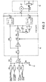
- the speed controller 16 comprises a summing device consisting of an operational amplifier A1 and resistors R1-R6. Two resistors R1 and R2 are connected to the minus input of operational amplifier A1. The output of operational amplifier A1 is connected to the minus input via a resistor R5. The resistor R1 is acted upon by a signal representative of the target filling level. This can be tapped, for example, by a potentiometer. A signal for the discharge volume, which is fed to the resistor R2, can also be generated by a potentiometer. Two resistors R3 and R4 are connected to the plus input of operational amplifier A1. Furthermore, the plus input is connected to ground via a resistor R6. The above-mentioned signal for the filling volume is fed to the resistor R3, while the signal representative of the actual filling level of the memory is fed to the resistor R4 receive the sum signal S at its output in accordance with the above equation.
- a resistor R7 is in series with an operational amplifier A2, a switch Si, a resistor R9 and an operational amplifier A3.
- an operational amplifier A3 With the output of the operational amplifier A3 is the input of an operator amplifier A4 connected, the output of which in turn is connected via a resistor R10 to the input of operational amplifier A4.
- a capacitor C1 is connected in parallel with the operational amplifier A4 and the resistor R10.
- the output of the operational amplifier A3 is connected to the respective input of a first comparator CO I and a second comparator CO II. Furthermore, the output of the operational amplifier A3 is connected via the resistor R8 to the connecting line of the resistor R7 and the operational amplifier A2.
- the size of the resistor R10 is much larger than the resistor R9.
- the reference voltage of the comparator CO I is positive (Ug> 0), while the reference voltage of the comparator CO II has the same amount, but has a negative sign (U s ⁇ 0).
- the output signals of the comparators CO I and CO II each control a switch S2 or S3, of which the two switch contacts of the one switch S2 are connected to a positive voltage source or the output A of the converter 18 and the two switch contacts of the other switch S3 are between one negative voltage source and the mentioned output A are connected. If the switch S2 is closed by an output signal of the comparator CO I, a positive potential is thus supplied to the output A of the converter 18, while a negative potential is supplied to the output A by closing the switch S3.
- the switches S2 and S3 are preferably relays, while the switch S1 is preferably designed as a field effect transistor.
- the input A of a servo control device 19 is connected to the output A of the converter 18.
- the latter comprises a motor M which moves a wiper SCH of a potentiometer R11 in one direction or the other when positive or negative potential is supplied to it.
- the voltage tapped at the potentiometer R11 is fed to the drive motor 15.
- Fig. 2 operates as follows. At the output of the summing device, i.e. H. At the output of the operational amplifier A1, a sum signal S is generated according to the above equation. At the beginning of an ejection process, switch S1 is closed for approx. 10 ms. The signal to close switch S1 is obtained by ANDing the signals «Form ready and « Minimum fill level of the memory reached •. This can, for. B. when starting the machine, the shape can be brought into preparation without the memory already having to be filled. Closing switch S1 has the result that control loop A1, Si, R9, A3, R8 is closed. As a result, a voltage proportional to the sum signal is established at the output of A3.
- the motor moves the grinder SCH of the potentiometer R11, as a result of which the speed of the motor drive 15 is reduced in this case.
- the switch S2 is closed for a certain period of time, which results in an increase in the engine speed.
- the discharge of the capacitor C1 takes longer, the greater the amount of the sum signal S.
- the relevant switch S2 or S3 is closed for a more or less long time.
- the converter 18 thus causes the motor M of the servo control device 19 to be supplied with a potential for a certain period of time.
- the time period depends on the amplitude of the sum signal S.
- the sign of the sum signal S determines the direction in which the motor M is rotated, i. H. whether the speed of the drive motor 15 and thus the screw conveyor 8 is increased or decreased.
- the response sensitivity of the control device can be set by selecting the reference voltage U s of the two comparators.
- the value of the target fill level supplied to the summing device is set so that it is approximately 105% of the minimum fill level of the memory. If the storage tank is filled up to the minimum filling level, the stored volume corresponds exactly to the output volume. The addition of 5% ensures that there is always enough material in the memory 11 before each ejection process.
- the speed of the conveying device has been set correctly, and that the accumulator is filled up to the target filling level of, for example, 105% and ejected to 5% (see FIGS. 3 and 4).
- the difference between the actual filling level and the target filling level is zero, so that the known method does not correct the speed. Since the difference between the filling volume and the discharge volume is also zero, the sum signal S also becomes zero in the method according to the invention, so that the speed of rotation also here is not corrected.
- the speed is increased again by approx. 5%.
- the sum signal is:
- the speed of the conveyor is therefore increased by approx. 5%.
Landscapes
- Engineering & Computer Science (AREA)
- Mechanical Engineering (AREA)
- Manufacturing & Machinery (AREA)
- Blow-Moulding Or Thermoforming Of Plastics Or The Like (AREA)
- Extrusion Moulding Of Plastics Or The Like (AREA)
- Basic Packing Technique (AREA)
- Processing And Handling Of Plastics And Other Materials For Molding In General (AREA)
- Control Of Conveyors (AREA)
Description
Die Erfindung bezieht sich auf ein Verfahren zum Regeln des Füllungsgrades eines Speichers in einer Fördereinrichtung eines Extruders gemäß dem Oberbegriff des Anspruchs 1, sowie auf eine Vorrichtung zum Durchführen des Verfahrens.The invention relates to a method for regulating the degree of filling of a store in a conveyor of an extruder according to the preamble of claim 1, and to a device for performing the method.
Um einen Blasformkörper herzustellen, wird in einem Extruder zuerst ein zylindrischer Vorformling gebildet, der in einem sich daran anschließenden Arbeitsgang in einer Blasform auf den gewünschten Außendurchmesser gebracht wird. In dem Extruder ist eine Fördereinrichtung vorgesehen, die das Material für den Blasformkörper in einem Speicher fördet, aus dem bei jedem Arbeitszyklus ein bestimmtes Volumen für die Blasform entnommen werden kann. Um die Maschine möglichst effizient auszunutzen, muß dafür gesorgt werden, daß das Material möglichst genau dann in die Form gegeben wird, sobald diese zur Aufnahme bereit ist. Dies bedeutet, daß die Fördermenge der Fördereinrichtung so eingestellt werden muß, daß in der zur Verfügung stehenden Zeit die benötigte Menge Material in den Speicher gefördert wird. Abweichungen der Fördermenge von der benötigten Sollfördermenge führen zu Nachteilen.In order to produce a blow molding, a cylindrical preform is first formed in an extruder, which is then brought to the desired outside diameter in a blow mold in a subsequent operation. A conveyor device is provided in the extruder, which conveys the material for the blow molding in a store, from which a specific volume for the blow mold can be removed during each working cycle. In order to use the machine as efficiently as possible, it must be ensured that the material is put into the mold as precisely as possible as soon as it is ready to be picked up. This means that the delivery rate of the conveyor must be set so that the required amount of material is fed into the memory in the time available. Deviations in the delivery rate from the required delivery rate lead to disadvantages.
Bei einem bekannten Verfahren der eingangs genannten Art wird am Ende jedes Ausstoßvorgangs des Materials aus dem Speicher der Füllungsgrad des Speichers abgefragt. Wird eine Abweichung von einem vorgegebenen Soll- füllungsgrad festgestellt, wird die Fördermenge der Fördereinrichtung entsprechend erhöht, bzw. vermindert, indem die Drehzahl der Fördereinrichtung erhöht, bzw. erniedrigt wird.In a known method of the type mentioned at the end of each ejection process of the material from the memory, the degree of filling of the memory is queried. If a deviation from a predetermined degree of filling is determined, the delivery rate of the conveyor is increased or decreased accordingly by increasing or decreasing the speed of the conveyor.
Bei diesem bekannten Extruder dient ein Zylinder als Materialspeicher. Durch das geförderte Material wird ein in dem Zylinder angeordneter Kolben zurückgeschoben. Die Stellung des Kolbens und damit der Füllungsgrad am Anfang eines Ausstoßzyklus hängt dadurch von der Drehzahl der Fördereinrichtung ab. Die Regelung der Drehzahl erfolgt nach Maßgabe des festgestellten Füllungsgrades. Diese Regelung führt dann zu nachteiligen Schwingungen, d. h., Anfangs- und Endpunkt des Kolbenhubweges schwanken um einen Mittelwert, wenn das Ausstoßvolumen pro Zyklus konstant gehalten wird. Dies beeinträchtigt besonders bei großen Fördermengen ein einwandfreies Funktionieren der Maschine.In this known extruder, a cylinder serves as a material store. A piston arranged in the cylinder is pushed back by the conveyed material. The position of the piston and thus the degree of filling at the beginning of an ejection cycle depends on the speed of the conveyor. The speed is regulated according to the determined degree of filling. This regulation then leads to disadvantageous vibrations, i. that is, the start and end points of the piston stroke travel fluctuate by an average value if the discharge volume per cycle is kept constant. This affects the proper functioning of the machine, especially with large flow rates.
Bei einem anderen Verfahren, bei dem die Drehzahl einer Extruderfördereinrichtung nicht geregelt sondern manuell eingestellt wird, können zwar keine Schwingungen auftreten, jedoch müssen dafür andere Nachteile in Kauf genommen werden. Nach einem solchen Verfahren wird beim Ausstoßvorgang der Kolben des Speichers stets bis zu einer bestimmten Stelle geschoben. Ist hierbei die Extruderdrehzahl zu langsam eingestellt, muß eine Formwartezeit in Kauf genommen werden, da der Speicher bei Formbereitstellung noch nicht genügend gefüllt ist. Ist die Drehzahl zu hoch, wird der Speicher mehr als notwendig gefüllt und es wird deshalb, da der Schubkolben bis zu einer bestimmten Wegmarke vorgeschoben wird, zu viel Material ausgestoßen.In another method, in which the speed of an extruder conveyor is not regulated but set manually, no vibrations can occur, but other disadvantages have to be accepted. According to such a method, the piston of the accumulator is always pushed to a certain point during the ejection process. If the extruder speed is set too slowly, a mold waiting time must be accepted, since the memory is not yet sufficiently filled when the mold is made available. If the speed is too high, the accumulator is filled more than necessary and, because the thrust piston is pushed up to a certain way mark, too much material is expelled.
Der Erfindung liegt die Aufgabe zugrunde, ein Verfahren zum Regeln des Füllungsgrades eines Speichers in einer Fördereinrichtung eines Extruders der eingangs genannten Art anzugeben, welches ohne Schwingungseffekte arbeitet.The invention is based on the object of specifying a method for regulating the degree of filling of a store in a conveying device of an extruder of the type mentioned at the outset, which works without oscillation effects.
Ausgehend von einem Verfahren der eingangs genannten Art, wird diese Aufgabe erfindungsgemäß durch die im Kennzeichen des Anspruchs 1 angegebenen Merkmale gelöst.Starting from a method of the type mentioned at the outset, this object is achieved according to the invention by the features specified in the characterizing part of claim 1.
Wurde bei dem bekannten Verfahren die Drehzahl der Fördereinrichtung des Extruders nur in Abhangigkeit vom Ist-Füllungsgrad des Speichers eingestellt, so sieht demgegenüber das erfindungsgemäße Verfahren vor, auch das tatsächliche Füllvolumen des Speichers mit als Regelgröße zu verarbeiten. Der Ist-Füllungsgrad leitet sich bei einem Speicher mit Ausstoßkolben aus der Endstellung des Kolbens vor Beginn des Ausstoßens ab, das Füllvolumen dagegen ergibt sich aus dem Rückführweg des Kolbens beim Wiederauffüllen des Speichers und dem Kolbenquerschnitt. Das erfindungsgemäße Verfahren verhindert ein Schwingen der Anordnung, wodurch ein einwandfreies Funktionieren des Extruders gewährleistet ist.If, in the known method, the speed of the conveyor of the extruder was set only as a function of the actual degree of filling of the store, the method according to the invention provides, in contrast, to also process the actual fill volume of the store as a controlled variable. In the case of a reservoir with ejection piston, the actual filling level is derived from the end position of the piston before ejection begins, the filling volume, however, results from the return path of the piston when the reservoir is refilled and the piston cross-section. The method according to the invention prevents the arrangement from vibrating, thereby ensuring that the extruder functions properly.
Eine vorteilhafte Weiterbildung des Verfahrens ist in Anspruch 2 angegeben. Besteht beispielsweise das Summensignal aus einer Spannung, so wird diese Spannung in ein entsprechend langes Zeitintervall umgewandelt. Während dieses Zeitintervalls wird die Drehzahl der Fördereinrichtung nachgestellt. Das Einstellen der Drehzahl erfolgt demnach proportional zu der Amplitude des Summensignals. Hierdurch wird eine schnelle und exakte Regelung gewährleistet.An advantageous development of the method is specified in
Eine bevorzugte Weiterbildung der Erfindung ist in Anspruch 3 angegeben. Durch diese Maßnahme wird sichergestellt, daß keine Formwartezeiten auftreten, weil der Mindest-Füllungsgrad des Speichers mit Sicherheit erreicht wird, wenn die Form zur Aufnahme von Material bereitsteht.A preferred development of the invention is specified in
Das in Anspruch 4 angegebene Verfahren ermöglicht ein einfaches Anfahren des Extruders. Durch die « UND » - Verknüpfung der beiden Bedingungen « Formbereitschaft » und « Mindestfüllungsgrad erreicht », kann beim Anfahren der Maschine die Form unabhängig vom Füllungsgrad des Speichers in Bereitstellung gebracht werden.The method specified in
Eine Vorrichtung zum Durchführen des erfindungsgemäßen Verfahrens ist in Anspruch 5 angegeben. Bei der erfindungsgemäßen Vorrichtung sind nur relativ wenig Bauteile erforderlich. Der zur Gewinnung der Signale für den Ist-Füllungsgrad und das Füllvolumen erforderliche Positionsgeber ist in der Regel bei den in Frage kommenden Extrudern schon vorhanden; er dient beispielsweise zum Erzeugen von Steuersignalen, die beim Formungsprozeß benötigt weiden. Der Meßwandler zum Erzeugen des Speicher-Füllvolumen-Signals kann beispielsweise ein Integrator sein, der ein dem Weg des Ausstoßkolbens beim Füllen des Speichers entsprechendes Signal aufintegriert. Die erfindungsgemäße Vorrichtung kann leicht in bereits vorhandene Extruder eingebaut werden.A device for performing the method according to the invention is specified in
Im folgenden wird ein Ausführungsbeispiel der Erfindung anhand der Zeichnung näher erläutert. Es zeigen :
- Figur 1 eine schematische Darstellung eines Extruders mit regelbarer Fördereinrichtung,
Figur 2 ein vereinfachtes Blockschaltbild eines Drehzahlreglers für die in Fig. 1 gezeigte Fördereinrichtung,Figur 3 ein Zeitdiagramm zum Veranschaulichen der Regelung gemäß dem Stand der Technik, undFigur 4 ein Zeitdiagramm, das das Regelverhalten gemäß der Erfindung verdeutlicht.
- FIG. 1 shows a schematic illustration of an extruder with a controllable conveying device,
- FIG. 2 shows a simplified block diagram of a speed controller for the conveyor device shown in FIG. 1,
- Figure 3 is a timing diagram illustrating the control according to the prior art, and
- Figure 4 is a timing diagram that illustrates the control behavior according to the invention.
Der in Fig. 1 dargestellte Extruder enthält einen Werkzeugkopf 1 mit einem bewegbaren Dorn 2, der in dem Werkzeugkopf 1 je nach seiner axialen Stellung eine im Querschnitt veränderbare Austrittsöffnung 3 bildet, durch die ein plastifizierter extrudierbarer Werkstoff preßbar ist, um einen Vorformling 4 zu bilden. Dieser Vorformling 4 wird anschließend in einer nicht dargestellten Blasform zu dem gewünschten Erzeugnis, beispielsweise einer Flasche, geformt. Eine Plastifiziereinrichtung 5 ist mit einer geheizten Kammer 6 versehen, in die ein Werkstoffgranulat über einen Beschickungstrichter 7 eingebbar ist. In der Kammer 6 befindet sich eine drehbare Förderschnecke 8, die den durch Wärmeeinwirkung plastifizierten Werkstoff in einen Kanal 9 drückt. Der Kanal 9 mündet in einen Speicherzylinder 11, In dem ein Kolben 12 verschiebbar angeordnet ist. An der Kolbenstange 13 des Kolbens 12 ist ein Positionsgeber 14 angeordnet, der z. B. durch ein Potentiometer gebildet ist, mit dem die jeweilige axiale stellung des Kolbens 12 durch ein elektrisches Signal wiedergebbar ist.The extruder shown in Fig. 1 contains a tool head 1 with a
Die Förderschnecke 8 wird durch einen Antriebsmotor 15 gedreht. Mit .dem Antriebsmotor 15 steht ein Drehzahlregler 16 in Verbindung, durch den die Drehzahl des Antriebsmotors 15 veränderbar ist.The
Der Extruder arbeitet wie folgt. Der Antriebsmotor 15 dreht die Förderschnecke 8 mit einer Geschwindigkeit, die von der ihm zugeführten Spannung abhängt, Diese Spannung wird durch den Drehzahlregler bestimmt. Angenommen, der Kolben 12 befinde sich nach einem Ausstoßvorgang in seiner rechten Stellung kurz vor der Einschnürung des Speichers 11, Die Austrittsöffnung 3 ist geschlossen, Durch den Kanal 9 wird der Werkstoff in den Speicher 11 gedrückt, wodurch der Kolben 12 mit der Kolbenstange 13 nach links geschoben wird. Bei dieser Bewegung wird über den Positionsgeber und einen nicht dargestellten Meßwandler ein Speicher-Füllvolumen-Signal erzeugt, welches das tatsächliche Füllvolumen repräsentiert. Weiterhin ist von dem Positionsgeber direkt ein für den Ist-Füllungsgrad des Speichers repräsentatives Signal abgreifbar. Erreicht dieses Signal einen vorbestimmten Wert, und ist die (nicht dargestellte) Form für die Materialaufnahme bereit, so wird der Kolben 12 durch eine nicht dargestellte Schubvorrichtung nach rechts gedrückt, während gleichzeitig die Austrittsöffnung 3 geöffnet wird. Die Werte des Füllvolumens und des Ist-Füllungsgrades werden dem Drehzahlregler 16 zugeführt, um dort weiterverarbeitet zu werden. Ein so gewonnenes Steuersignal wird dazu verwendet, die dem Antriebsmotor 15 zugeführte Spannung ggf. zu verändern, um den Materialsdurchsatz durch den Kanal 9, der sich an die Förderschnecke anschließt, zu variieren.The extruder works as follows. The
In dem Drehzahlregler 16 werden die Signale für den Ist-Füllungsgrad und das jeweilige tatsächliche Füllvolumen des Speichers mit den voreingestellten Werten für den Soll-Füllungsgrad und das Ausstoßvolumen, welches entsprechend einer vorgegebenen Größe des Kolbenhubes gleichfalls einen vorbestimmten Wert besitzt, arithmetisch verknüpft, um ein Summensignal S gemäß folgender Formel zu erhalten :![]()
![]()
Anhand von Fig. 2 soll im folgenden der Drehzahlregler 16 näher erläutert werden. Er umfaßt eine aus einem Operationsverstärker A1 und Widerständen R1-R6 bestehende Summiereinrichtung. An den Minus-Eingang des Operationsverstärkers A1 sind zwei Widerstände R1 und R2 angeschlossen. Der Ausgang des Operationsverstärkers A1 Ist mit dem Minus-Eingang über einen Widerstand R5 verbunden. Der Widerstand R1 wird von einem für den Soll-Füllungsgrad repräsentativen Signal beaufschlagt. Dieses kann beispielsweise von einem Potentiometer abgegriffen werden. Ebenfalls durch ein Potentiometer erzeugbar ist ein Signal für das Ausstoßvolumen, welches dem Widerstand R2 zugeführt wird. An den Plus-Eingang des Operationsverstärkers A1 sind zwei Widerstände R3 und R4 angeschlossen. Weiterhin liegt der Plus-Eingang über einen Widerstand R6 an Masse, Dem Widerstand R3 wird das oben erwähnte Signal für das Füllvolumen zugeführt, während dem Widerstand R4 das für den Ist-Füllungsgrad des Speichers repräsentative Signal zugeleitet wird, Durch diese Besohaltung des Operationsverstärkers A1 wird an dessen Ausgang das Summensignal S gemäß obiger Gielchung.erhalten.The
An den Ausgang der Summlerelnrichtung, 17 schließt sich ein Spannurigs/Impuledauer-Umsetzer 18 an, Ein Widerstand R7 liegt In Serie zu einem Operationsverstärker A2, einem Schalter Si, einem Widerstand R9 und einem Operationsverstärker A3. Mit dem Ausgang des Operationsverstärkers A3 Ist der Eingang eines Operätlonsverstärkers A4 verbunden, dessen Ausgang wiederum über einen Widerstand R10 mit dem Eingang des Operationsverstärkers A4 verbunden ist. Parallel zu dem Operationsverstärker A4 und dem Widerstand R10 ist ein Kondensator C1 geschaltet. Der Ausgang des Operationsverstärkers A3 steht mit dem jeweiligen Eingang eines ersten Komparators CO I und eines zweiten Komparators CO II in Verbindung. Weiterhin ist der Ausgang des Operationsverstärkers A3 über den Widerstand R8 mit der Verbindungsleitung des Widerstandes R7 und des Operationsverstärkers A2 verbunden. Die Größe des Widerstandes R10 ist wesentlich höher als der Widerstandes R9. Die Referenzspannung des Komparators CO I ist positiv (Ug > 0), während die Referenzspannung des Komparators CO II denselben Betrag hat, jedoch negatives Vorzeichen besitzt (Us < 0). Die Ausgangssignale der Komparatoren CO I und CO II steuern jeweils einen Schalter S2, bzw. S3, von denen die beiden Schaltkontakte des einen Schalters S2 an eine positive Spannungsquelle bzw. den Ausgang A des Umsetzers 18 und die beiden Schaltkontakte des anderen Schalters S3 zwischen eine negative Spannungsquelle und den erwähnten Ausgang A angeschlossen sind. Wird der Schalter S2 durch ein Ausgangssignal des Komparators CO I geschlossen, wird dem Ausgang A des Umsetzers 18 somit ein positives Potential zugeführt, während durch Schließen des Schalters S3 dem Ausgang A ein negatives Potential zugeführt wird. Bei den Schaltern S2 und S3 handelt es sich vorzugsweise um Relais, während der Schalter S1 vorzugsweise als Feldeffekttransistor ausgebildet ist.At the output of the summing
Mit dem Ausgang A des Umsetzers 18 steht der Eingang einer Servo-Steuereinrichtung 19 in Verbindung. Letztere umfaßt einen Motor M, der einen Schleifer SCH eines Potentiometers R11 in die eine oder andere Richtung bewegt, wenn ihm positives, bzw. negatives Potential zugeführt wird. Die an dem Potentiometer R11 abgegriffene Spannung wird dem Antriebsmotor 15 zugeführt.The input A of a
Die in Fig. 2 gezeigte Schaltung arbeitet wie folgt. Am Ausgang der Summiereinrichtung, d. h. am Ausgang des Operationsverstärkers A1 wird ein Summensignal S nach obiger Gleichung erzeugt. Zu Beginn eines Ausstoßvorganges wird der Schalter S1 für ca. 10 ms geschlossen. Das Signal zum Schließen des Schalters S1 wird erhalten durch UND-Verknüpfung des Signals « Form bereit und « Mindest-Füllungsgrad des Speichers erreicht •. Hierdurch kann z. B. beim Anfahren der Maschine die Form in Bereitstellung gebracht werden, ohne daß der Speicher schon gefüllt zu sein braucht. Das Schließen des Schalters S1 hat zur Folge, daß der Regelkreis A1, Si, R9, A3, R8 geschlossen wird. Demzufolge stellt sich am Ausgang von A3 eine dem Summensignal proportionale Spannung ein. Da der Wert des Widerstandes R10 wesentlich größer ist als der des Widerstandes R9, beeinflußt der durch den Widerstand R10 fließende Strom die sich am Ausgang von A3 einstellende Spannung nicht. Angenommen, das Summensignals S sei positiv. Dies bedeutet, daß die Drehzahl der Förderschnecke 8 zu hoch ist. In diesem Fall wird der Schalter S3 geschlossen und dem Motor M negatives Potential zugeführt. Nach Öffnen des Schalters S1 wird der auf die Ausgangsspannung von A3 aufgeladene Kondensator C1 über den Operationsverstärker A4 und den Widerstand R10 entladen. Hierdurch nimmt die Ausgangsspannung des Operationsverstärkers A3 bis auf Null ab. Unterschreitet der Betrag der Spannung die Schwellenspannung U, des Komparators CO II, so öffnet der Kontakt S3. In der Zeit zwischen Schließen und Öffnen des Schalters S3 bewegt der Motor den Schleifer SCH des Potentiometers R11, wodurch in diesem Fall die Drehzahl des Motorantriebes 15 verringert wird. Ist das Summensignal S negativ, so wird der Schalter S2 für eine bestimmte Zeitdauer geschlossen, was ein Erhöhen der Motordrehzahl zur Folge hat. Das Entladen des Kondensators C1 dauert um so länger, je größer der Betrag des Summensignals S ist. Dementsprechend wird der betreffende Schalter S2 oder S3 für eine mehr oder weniger lange Zeit geschlossen. Des Umsetzer 18 bewirkt also, daß dem Motor M der Servo-Steuereinrichtung 19 für eine bestimmte Zeitdauer ein Potential zugeführt wird. Die Zeitdauer hängt von der Amplitude des Summensignals S ab. Das Vorzeichen des Summensignals S bestimmt, in welche Richtung der Motor M gedreht wird, d. h. ob die Drehzahl des Antriebsmotors 15 und somit der Förderschnecke 8 erhöht, bzw. vermindert wird.The circuit shown in Fig. 2 operates as follows. At the output of the summing device, i.e. H. At the output of the operational amplifier A1, a sum signal S is generated according to the above equation. At the beginning of an ejection process, switch S1 is closed for approx. 10 ms. The signal to close switch S1 is obtained by ANDing the signals «Form ready and« Minimum fill level of the memory reached •. This can, for. B. when starting the machine, the shape can be brought into preparation without the memory already having to be filled. Closing switch S1 has the result that control loop A1, Si, R9, A3, R8 is closed. As a result, a voltage proportional to the sum signal is established at the output of A3. Since the value of the resistor R10 is considerably larger than that of the resistor R9, the current flowing through the resistor R10 does not influence the voltage which arises at the output of A3. Assume that the sum signal S is positive. This means that the speed of the
Durch Wahl der Referenzspannung Us der beiden Komparatoren läßt sich die Ansprechempfindlichkeit der Regeleinrichtung einstellen.The response sensitivity of the control device can be set by selecting the reference voltage U s of the two comparators.
Wird die Referenzspannung U, relativ groß gewählt, so wird die Drehzahl des Motorantriebs bei kleinen Summensignalen nicht verändert.If the reference voltage U, is chosen to be relatively large, the speed of the motor drive is not changed with small sum signals.
Der der Summiereinrichtung zugeführte Wert des Soll-Füllungsgrades wird so eingestellt, daß er etwa 105 % des Mindest-Füllungsgrades des Speichers beträgt. Ist der Speicher bis zum Mindest-Füllungsgrad gefüllt, so entspricht das gespeicherte Volumen genau dem Ausstoßvolumen. Durch den Zuschlag von 5% wird sichergestellt, daß vor jedem Ausstoßvorgang stets genug Material im Speicher 11 vorhanden ist.The value of the target fill level supplied to the summing device is set so that it is approximately 105% of the minimum fill level of the memory. If the storage tank is filled up to the minimum filling level, the stored volume corresponds exactly to the output volume. The addition of 5% ensures that there is always enough material in the
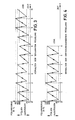
Im folgenden soll der Unterschied zwischen der erfindungsgemäßen Regelung und der bekannten Regelung anhand der Fig. 3 und 4 erläutert werden.The difference between the regulation according to the invention and the known regulation will be explained below with reference to FIGS. 3 and 4.
Zur Veranschaulichung sei angenommen, die Drehzahl der Fördereinrichtung wäre richtig eingestellt, und der Speicher werde bis zum Soll- füllungsgrad von beispielsweise 105 % gefüllt und bis auf 5 % ausgestoßen (s. Fig. 3 und 4). Die Differenz zwischen Ist-Füllungsgrad und Soll- Füllungsgrad ist Null, so daß beim bekannten Verfahren keine Korrektur der Drehzahl erfolgt. Da die Differenz zwischen Füllvolumen und Ausstoßvolumen ebenfalls Null ist, wird beim erfindungsgemäßen Verfahren das Summensignal S ebenfalls Null, so daß die Drehzahl auch hier nicht korrigiert wird.As an illustration, it is assumed that the speed of the conveying device has been set correctly, and that the accumulator is filled up to the target filling level of, for example, 105% and ejected to 5% (see FIGS. 3 and 4). The difference between the actual filling level and the target filling level is zero, so that the known method does not correct the speed. Since the difference between the filling volume and the discharge volume is also zero, the sum signal S also becomes zero in the method according to the invention, so that the speed of rotation also here is not corrected.
Wird nun angenommen, daß aus irgendeinem Grund die Fördermenge der Fördereinrichtung trotz konstanter Drehzahl (z. B. durch andere Zusammensetzung des Kunststoffmaterials) um ca. 5 % ansteigt, so ist zum Zeitpunkt t = 2 der Füllungsgrad des Speichers 110%.If it is now assumed that for some reason the delivery rate of the conveyor device increases by approx. 5% despite constant speed (e.g. due to a different composition of the plastic material), the filling level of the accumulator is 110% at time t = 2.
Beim bekannten Verfahren (Fig. 3) wird nun, da der Ist-Füllungsgrad den Soll-Füllungsgrad übersteigt, die Drehzahl der Fördereinrichtung um ca. 5 % verkleinert, so daß das Füllvolumen zwischen t = 2 und t = 3 ca. 100 % ist. Da der Speicher nach dem Ausstoßvorgang bei 10% zu füllen beginnt, ist zum Zeitpunkt t = 3 der Füllungsgrad des Speichers widerum 110%. Dadurch wird die Drehzahl der Fördereinrichtung nochmals um ca. 5 % verkleinert. Das Füllvolumen beträgt jetzt ca. 95 %. Zum Zeitpunkt t = 4 ist der Füllungsgrad des Speichers also ca. 105 %, so daß die Abweichung des Ist-Füllungsgrades vom Soll-Füllungsgrad Null wird, d. h. die Drehzahl wird zum Zeitpunkt t = 4 nicht verändert. Da das füllvolumen immer noch 95 % beträgt, ist zum Zeitpunkt t = 5 der Füllungsgrad des Speichers ca. 100%. Die Drehzahl wird also wieder um ca. 5 % vergrößert. Das Füllvolumen beträgt jetzt 100 %, so daß zum Zeitpunkt t = 6 die Drehzahl wieder um ca. 5 % erhöht wird. Zum Zeitpunkt t = 7 wird die Drehzahl nicht verändert, dadurch ist zum Zeitpunkt t = 8 der Füllungsgrad wieder 110 %, usw. Man sieht, daß diese Art der Regelung nicht stabil ist.In the known method (FIG. 3), since the actual filling level exceeds the target filling level, the speed of the conveyor is reduced by approximately 5%, so that the filling volume between t = 2 and t = 3 is approximately 100% . Since the memory begins to fill at 10% after the ejection process, the degree of filling of the memory is again 110% at time t = 3. This reduces the speed of the conveyor by another 5%. The filling volume is now approx. 95%. At time t = 4, the degree of filling of the memory is therefore approximately 105%, so that the deviation of the actual degree of filling from the target degree of filling becomes zero, i. H. the speed is not changed at time t = 4. Since the filling volume is still 95%, the filling level of the reservoir is approx. 100% at time t = 5. The speed is increased again by approx. 5%. The filling volume is now 100%, so that the speed is increased again by approx. 5% at time t = 6. At time t = 7, the speed is not changed, so that at time t = 8 the degree of filling is again 110%, etc. It can be seen that this type of control is not stable.
Beim erfindungsgemäßen Verfahren (Fig. 4) dagegen wird zum Zeitpunkt t = 2 die Drehzahl der Fördereinrichtung um ca. 10 % verkleinert, da erstens der Ist-Füllungsgrad den Soll-Füllungsgrad um 5 % übersteigt und zweitens das Füllvolumen um 5 % höher als das Ausstoßvolumen ist. Das Summensignal ist:![]()
![]()
Das Füllvolumen beträgt nach der Korrektur ca. 95 %, so daß zum Zeitpunkt t = 3 der Füllungsgrad des Speichers ca. 105 % beträgt, was dem Soll- Füllungsgrad entspricht. Da das Füllvolumen des Speichers 95 % beträgt, wird das Summensignal![]()
![]()
Die Drehzahl der Fördereinrichtung wird also um ca. 5% vergrößert. Das Füllvolumen beträgt jetzt 100 %. Da zum Zeitpunkt t = 4 auch der Ist-Füllungsgrad gleich dem Sollfüllungsgrad ist, wird das Summensignal Null, so daß die Drehzahl der Fördereinrichtung nicht mehr verändert wird. Die Drehzahl der Fördereinrichtung ist bei diesem Beispiel zum Zeitpunkt t = 3 wieder richtig eingestellt.The speed of the conveyor is therefore increased by approx. 5%. The filling volume is now 100%. Since the actual filling level is also equal to the target filling level at time t = 4, the sum signal becomes zero, so that the speed of the conveyor device is no longer changed. In this example, the speed of the conveyor is set correctly again at
Claims (9)
Applications Claiming Priority (2)
| Application Number | Priority Date | Filing Date | Title |
|---|---|---|---|
| DE2813241A DE2813241C2 (en) | 1978-03-28 | 1978-03-28 | Method for regulating the degree of filling of a store in a conveying device of an extruder and device for carrying out this method |
| DE2813241 | 1978-03-28 |
Publications (4)
| Publication Number | Publication Date |
|---|---|
| EP0004281A2 EP0004281A2 (en) | 1979-10-03 |
| EP0004281A3 EP0004281A3 (en) | 1979-10-31 |
| EP0004281B1 EP0004281B1 (en) | 1981-03-04 |
| EP0004281B2 true EP0004281B2 (en) | 1984-04-11 |
Family
ID=6035532
Family Applications (1)
| Application Number | Title | Priority Date | Filing Date |
|---|---|---|---|
| EP79100465A Expired EP0004281B2 (en) | 1978-03-28 | 1979-02-16 | Method for the control of the filling degree of a reservoir in a feed means of an extruder and apparatus for applying this method |
Country Status (4)
| Country | Link |
|---|---|
| US (1) | US4224561A (en) |
| EP (1) | EP0004281B2 (en) |
| JP (1) | JPS54127966A (en) |
| DE (1) | DE2813241C2 (en) |
Families Citing this family (13)
| Publication number | Priority date | Publication date | Assignee | Title |
|---|---|---|---|---|
| DE2940904A1 (en) * | 1979-10-09 | 1981-04-23 | Moog GmbH, 7030 Böblingen | METHOD AND DEVICE FOR REGULATING THE PROCESSING PERFORMANCE OF AN EXTRUDER |
| CH655793A5 (en) * | 1982-02-01 | 1986-05-15 | Maag Zahnraeder & Maschinen Ag | PROFILE MEASURING CONTROL DEVICE. |
| DE3414444A1 (en) * | 1984-04-17 | 1985-10-17 | Continental Gummi-Werke Ag, 3000 Hannover | EXTRUSION PRESS |
| DE3416552C2 (en) * | 1984-05-04 | 1994-05-19 | Recycloplast Ag | Method and device for dividing a plasticized strand of plastic emerging from a mouth |
| DE3809857A1 (en) * | 1988-03-24 | 1989-10-05 | Philips Patentverwaltung | BLOW MOLDING MACHINE FOR BLOW MOLDING OF HOLLOW BODIES WITH UPHOLSTERY CONTROL |
| DE3809856A1 (en) * | 1988-03-24 | 1989-10-05 | Philips Patentverwaltung | BLOW MOLDING MACHINE FOR BLOW MOLDING OF HOLLOW BODIES WITH WAITING PERIOD |
| JPH0539858Y2 (en) * | 1988-04-11 | 1993-10-08 | ||
| DE3936301A1 (en) * | 1989-11-01 | 1991-05-02 | Kautex Maschinenbau Gmbh | METHOD FOR PRODUCING HOLLOW BODIES FROM THERMOPLASTIC PLASTIC |
| JPH03274134A (en) * | 1990-03-26 | 1991-12-05 | Ube Ind Ltd | Resin supply device to die |
| JP4086916B2 (en) * | 1996-07-08 | 2008-05-14 | 九州日立マクセル株式会社 | Electric hair clipper |
| JP5889115B2 (en) * | 2012-06-06 | 2016-03-22 | オリンパス株式会社 | Kneading extrusion molding equipment |
| DE102012112110A1 (en) * | 2012-12-11 | 2014-06-12 | Kautex Maschinenbau Gmbh | Extrusion blow molding and apparatus for its implementation |
| DE102018209998B4 (en) * | 2018-06-20 | 2021-09-02 | Universität Stuttgart | Method and device for examining a thermoplastic material |
Family Cites Families (9)
| Publication number | Priority date | Publication date | Assignee | Title |
|---|---|---|---|---|
| DE1813421C3 (en) * | 1968-12-07 | 1974-12-12 | Indramat, Gesellschaft Fuer Industrierationalisierung Und Automatisierung Mbh, 8770 Lohr | Device for controlling the wall thickness of the plastic strand of an extruder |
| US3693946A (en) * | 1971-05-10 | 1972-09-26 | Cincinnati Milacron Inc | Plastication control for injection molding machines |
| JPS4953657A (en) * | 1972-09-25 | 1974-05-24 | ||
| DE2300171A1 (en) * | 1973-01-03 | 1974-07-11 | Bucher Guyer Ag Masch | PROCESS FOR REGULATING THE CURING TIME OF THE PLASTIC COMPOUND IN THE FORM OF INJECTION MOLDING MACHINE |
| JPS5344921B2 (en) * | 1973-07-19 | 1978-12-02 | ||
| US3865528A (en) * | 1973-11-01 | 1975-02-11 | Moog Inc | Extrusion apparatus having electronic interpolator |
| JPS5627132B2 (en) * | 1974-11-27 | 1981-06-23 | ||
| DE2544609C3 (en) * | 1975-10-06 | 1984-11-08 | Kautex Werke Reinold Hagen Gmbh, 5300 Bonn | Device for influencing the length of a preform made of thermoplastic material |
| JPS5374569A (en) * | 1976-12-15 | 1978-07-03 | Kayaba Industry Co Ltd | Apparatus for compensating length of parison in hollow plastic molding machine |
-
1978
- 1978-03-28 DE DE2813241A patent/DE2813241C2/en not_active Expired
-
1979
- 1979-02-16 EP EP79100465A patent/EP0004281B2/en not_active Expired
- 1979-03-09 JP JP2757979A patent/JPS54127966A/en active Granted
- 1979-03-16 US US06/021,151 patent/US4224561A/en not_active Expired - Lifetime
Also Published As
| Publication number | Publication date |
|---|---|
| EP0004281A2 (en) | 1979-10-03 |
| DE2813241B1 (en) | 1979-10-04 |
| DE2813241C2 (en) | 1984-08-30 |
| JPS6258282B2 (en) | 1987-12-04 |
| EP0004281A3 (en) | 1979-10-31 |
| US4224561A (en) | 1980-09-23 |
| JPS54127966A (en) | 1979-10-04 |
| EP0004281B1 (en) | 1981-03-04 |
Similar Documents
| Publication | Publication Date | Title |
|---|---|---|
| EP0004281B2 (en) | Method for the control of the filling degree of a reservoir in a feed means of an extruder and apparatus for applying this method | |
| DE2253506C3 (en) | Control device for the injection unit of a screw injection molding machine | |
| DE2417986C3 (en) | Device for regulating the pressure acting on a mass injected into an injection mold by an injection unit | |
| EP1929253B1 (en) | Method for controlling a dosing apparatus for liquid or pasty media | |
| DE2210854A1 (en) | CONTROL SYSTEM FOR INJECTION MOLDING MACHINE | |
| DE2836692A1 (en) | METHOD AND DEVICE FOR REDUCING THE RISK OF DAMAGE CAUSED BY EXTRUSIONS AT THE PARTIAL JOINTS OF INJECTION MOLDS | |
| DE3021978C2 (en) | ||
| DE10135345B4 (en) | An electric injection molding machine and method for controlling an electric injection molding machine | |
| DE69113869T2 (en) | Injection molding control with process-variable learning process. | |
| EP3870422B1 (en) | Method for operating an injection-molding machine, in particular with respect to improved constant mold filling, and injection-molding machine for carrying out the method | |
| DE69617974T2 (en) | COMBINATION CONTROL FOR INJECTION MOLDING | |
| EP0185984A2 (en) | Hydraulic device for the injection unit of a plastic material injection-moulding machine | |
| EP0707936B1 (en) | Process to determine the switch-over point in the production of an injection-moulded part | |
| DE4002398C2 (en) | Device for controlling the regulation of the molding conditions of an injection molding machine | |
| DE3809792A1 (en) | INJECTION MOLDING METHOD AND DEVICE | |
| DE19514070A1 (en) | Control method for an injection molding device | |
| DE10031087A1 (en) | Injection molding machine with a continuously operating plasticizing unit | |
| DE102007012199A1 (en) | Plastification mechanism e.g. extruder or injection molding machine, operating method, involves adjusting and/or maintaining fluid level of raw material in valve within fluid level range corresponding to optimal operating parameter range | |
| DE69305837T3 (en) | A hydraulically operated piston extrusion press | |
| DE2920559C2 (en) | Method and arrangement for regulating the extrusion speed and quantity of an extruder for plastics | |
| EP0334448B1 (en) | Blowmoulding machine for hollow articles with an adjustement of the residual volume | |
| DE2543088C3 (en) | Method for controlling an injection molding machine | |
| DE2229171A1 (en) | Level control system - using continuous radiant heat measurement of material | |
| EP0344342B1 (en) | Electrical control device providing control signals for the die movement of an extruder | |
| EP0003510A1 (en) | Ramp generator for producing a time control signal for operating an electric control device of an extruder |
Legal Events
| Date | Code | Title | Description |
|---|---|---|---|
| PUAI | Public reference made under article 153(3) epc to a published international application that has entered the european phase |
Free format text: ORIGINAL CODE: 0009012 |
|
| PUAL | Search report despatched |
Free format text: ORIGINAL CODE: 0009013 |
|
| AK | Designated contracting states |
Designated state(s): BE CH FR GB IT NL SE |
|
| AK | Designated contracting states |
Designated state(s): BE CH FR GB IT NL SE |
|
| 17P | Request for examination filed | ||
| GRAA | (expected) grant |
Free format text: ORIGINAL CODE: 0009210 |
|
| AK | Designated contracting states |
Designated state(s): BE CH FR GB IT NL SE |
|
| PG25 | Lapsed in a contracting state [announced via postgrant information from national office to epo] |
Ref country code: SE Effective date: 19810304 Ref country code: NL Effective date: 19810304 Ref country code: IT Free format text: LAPSE BECAUSE OF FAILURE TO SUBMIT A TRANSLATION OF THE DESCRIPTION OR TO PAY THE FEE WITHIN THE PRESCRIBED TIME-LIMIT;WARNING: LAPSES OF ITALIAN PATENTS WITH EFFECTIVE DATE BEFORE 2007 MAY HAVE OCCURRED AT ANY TIME BEFORE 2007. THE CORRECT EFFECTIVE DATE MAY BE DIFFERENT FROM THE ONE RECORDED. Effective date: 19810304 |
|
| NLV1 | Nl: lapsed or annulled due to failure to fulfill the requirements of art. 29p and 29m of the patents act | ||
| PLBI | Opposition filed |
Free format text: ORIGINAL CODE: 0009260 |
|
| 26 | Opposition filed |
Opponent name: KRUPP-KAUTEX GMBH Effective date: 19811124 |
|
| PUAH | Patent maintained in amended form |
Free format text: ORIGINAL CODE: 0009272 |
|
| STAA | Information on the status of an ep patent application or granted ep patent |
Free format text: STATUS: PATENT MAINTAINED AS AMENDED |
|
| ET1 | Fr: translation filed ** revision of the translation of the patent or the claims | ||
| PGFP | Annual fee paid to national office [announced via postgrant information from national office to epo] |
Ref country code: BE Payment date: 19840331 Year of fee payment: 6 |
|
| 27A | Patent maintained in amended form | ||
| AK | Designated contracting states |
Kind code of ref document: B2 Designated state(s): BE CH FR GB IT NL SE |
|
| PG25 | Lapsed in a contracting state [announced via postgrant information from national office to epo] |
Ref country code: BE Effective date: 19890228 |
|
| BERE | Be: lapsed |
Owner name: MOOG G.M.B.H. Effective date: 19890228 |
|
| PGFP | Annual fee paid to national office [announced via postgrant information from national office to epo] |
Ref country code: FR Payment date: 19920206 Year of fee payment: 14 |
|
| PGFP | Annual fee paid to national office [announced via postgrant information from national office to epo] |
Ref country code: GB Payment date: 19920210 Year of fee payment: 14 |
|
| PGFP | Annual fee paid to national office [announced via postgrant information from national office to epo] |
Ref country code: CH Payment date: 19920320 Year of fee payment: 14 |
|
| PG25 | Lapsed in a contracting state [announced via postgrant information from national office to epo] |
Ref country code: GB Effective date: 19930216 |
|
| PG25 | Lapsed in a contracting state [announced via postgrant information from national office to epo] |
Ref country code: CH Effective date: 19930228 |
|
| GBPC | Gb: european patent ceased through non-payment of renewal fee |
Effective date: 19930216 |
|
| PG25 | Lapsed in a contracting state [announced via postgrant information from national office to epo] |
Ref country code: FR Effective date: 19931029 |
|
| REG | Reference to a national code |
Ref country code: CH Ref legal event code: PL |
|
| REG | Reference to a national code |
Ref country code: FR Ref legal event code: ST |