EP0003816A1 - Outil de forage pour rocher - Google Patents
Outil de forage pour rocher Download PDFInfo
- Publication number
- EP0003816A1 EP0003816A1 EP79100476A EP79100476A EP0003816A1 EP 0003816 A1 EP0003816 A1 EP 0003816A1 EP 79100476 A EP79100476 A EP 79100476A EP 79100476 A EP79100476 A EP 79100476A EP 0003816 A1 EP0003816 A1 EP 0003816A1
- Authority
- EP
- European Patent Office
- Prior art keywords
- centering pin
- carrier
- rock drilling
- drilling tool
- tip
- Prior art date
- Legal status (The legal status is an assumption and is not a legal conclusion. Google has not performed a legal analysis and makes no representation as to the accuracy of the status listed.)
- Granted
Links
- 238000005553 drilling Methods 0.000 title claims abstract description 55
- 239000011435 rock Substances 0.000 title claims abstract description 18
- 238000005520 cutting process Methods 0.000 claims abstract description 35
- 239000000428 dust Substances 0.000 claims abstract description 17
- 230000002093 peripheral effect Effects 0.000 claims description 7
- 238000004519 manufacturing process Methods 0.000 description 4
- 230000015572 biosynthetic process Effects 0.000 description 2
- 230000004048 modification Effects 0.000 description 2
- 238000012986 modification Methods 0.000 description 2
- 230000005540 biological transmission Effects 0.000 description 1
- 238000010276 construction Methods 0.000 description 1
- 230000001771 impaired effect Effects 0.000 description 1
- 238000000034 method Methods 0.000 description 1
- 239000002245 particle Substances 0.000 description 1
- 238000011144 upstream manufacturing Methods 0.000 description 1
Images
Classifications
-
- B—PERFORMING OPERATIONS; TRANSPORTING
- B23—MACHINE TOOLS; METAL-WORKING NOT OTHERWISE PROVIDED FOR
- B23B—TURNING; BORING
- B23B51/00—Tools for drilling machines
- B23B51/04—Drills for trepanning
- B23B51/0426—Drills for trepanning with centering devices
-
- E—FIXED CONSTRUCTIONS
- E21—EARTH OR ROCK DRILLING; MINING
- E21B—EARTH OR ROCK DRILLING; OBTAINING OIL, GAS, WATER, SOLUBLE OR MELTABLE MATERIALS OR A SLURRY OF MINERALS FROM WELLS
- E21B10/00—Drill bits
- E21B10/36—Percussion drill bits
- E21B10/38—Percussion drill bits characterised by conduits or nozzles for drilling fluids
-
- E—FIXED CONSTRUCTIONS
- E21—EARTH OR ROCK DRILLING; MINING
- E21B—EARTH OR ROCK DRILLING; OBTAINING OIL, GAS, WATER, SOLUBLE OR MELTABLE MATERIALS OR A SLURRY OF MINERALS FROM WELLS
- E21B10/00—Drill bits
- E21B10/36—Percussion drill bits
- E21B10/40—Percussion drill bits with leading portion
-
- B—PERFORMING OPERATIONS; TRANSPORTING
- B23—MACHINE TOOLS; METAL-WORKING NOT OTHERWISE PROVIDED FOR
- B23B—TURNING; BORING
- B23B2226/00—Materials of tools or workpieces not comprising a metal
- B23B2226/75—Stone, rock or concrete
Definitions
- the invention relates to a rock drilling tool with the features stated in the preamble of claim 1.
- Rock drilling tools of this type are known as so-called cross impact drills.
- the carrier has radially projecting arms, at the ends of which the cutting bodies are arranged.
- the cutting bodies are arranged at a radial distance from the centering pin.
- the ring that is not crushed by the tip of the centering pin or the cutting elements during drilling. by hitting the shoulders formed by the support arms wrecked.
- the thus arising some very coarse-ni e g drilling dust occurs partially in the intermediate spaces between .the support arms, so that it falls into the face of the person holding the drilling machine during drilling in a ceiling through these gaps down.
- the drilling dust dampens the impact of the drilling tool on the end of the hole, so that the drilling performance is impaired.
- the manufacture of the carrier provided with radially projecting arms is also relatively complex.
- the invention has for its object to provide a rock drilling tool with arranged around a centering pin, which is easier to manufacture and has a better drilling performance than the known cross impact drill and by drilling the person performing the drilling work is not bothered by the drilling dust.
- the rock drilling tool according to claim 1.
- the carrier for the cutting body is designed as a circular disk, there is only a very narrow gap when drilling between the carrier disk and the bore wall. Only this narrow space makes it useful to provide a suction channel for the drilling dust in the tool body, since this ensures that; that the air currents arising during suction have a sufficient speed in the narrow space to prevent drilling dust from entering this space.
- the design of the carrier as a disc also ensures that the entire end face facing the tip of the centering pin contributes to the shattering of the drilling dust, so that it is ensured that the drilling dust is crushed so finely that it is sucked off completely through the suction channel can.
- the fine drilling dust components can not form a cushion that dampens the impact energy of the circular impact drill when drilling down in the known cross impact drill.
- the fine drilling dust in the rock drilling tool according to the invention is in any case removed more quickly than in the known cross impact drill by the suction process, so that overall a much better driving performance results.
- the tool body of the rock drilling tool according to the invention also has a much greater strength, so that it can be produced with the same strength as a cross drilling tool with a lower weight, which improves the transmission of the impact energy, which in turn contributes to increasing the drilling performance.
- the end face of the carrier disk facing the tip of the centering pin is essentially flat.
- a circumferential annular groove can be present in the end face of the carrier disk between the centering pin and the cutting bodies.
- the mouth opening of the suction channel connecting the suction channel to the drilling point can be arranged at any point on the side of the tool body facing the tip of the centering pin.
- the mouth opening is arranged in the free end of the centering pin and at an axial distance in front of the cutting edges of the cutting bodies fastened to the carrier disk.
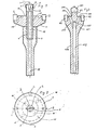
- FIGS. 1 and 2 The embodiment of a rock boring tool shown in FIGS. 1 and 2 has a tool body which consists of a carrier for cutting bodies 2 formed as a circular disk 1 and a centering pin 3, the shaft 4 of which has an external thread 5.
- the support disc 1 is provided with a central threaded bore for the external thread 5 of the centering pin 3.
- a tool shaft 6 is screwed onto this projecting end of the shaft 4.
- a cutting body 7 is fastened in a diametrical slot, the cutting edge 8 of which forms the tip 9 of the centering pin 3.
- the end face 11 of the carrier disk 1 facing the tip 9 is flat.
- the cutting body 2 are arranged at a radial distance from the centering pin 3, so that between the cutting body 7 of the centering pin and the cutting body 2 of the carrier disk 1 a part which is unprocessed when drilling through the cutting tools remains free from the flat end face 11 through the Stroke movement of the Tool is smashed.
- the tool shank 6 and the centering pin 3 are provided with axial bores 12 and 13 which are aligned with one another when the tool is screwed together.
- the bore 13 of the centering pin is designed as a blind hole and is connected by a branch hole, not shown in the drawing, to an opening which is arranged at the free end of the centering pin 3.
- the part of the centering pin 3 protruding from the end face 11 is so long that the mouth opening 14 is at an axial distance in front of the cutting edges of the cutting bodies 2. It is thereby achieved that the drilling dust upstream of the end face 11 only during drilling. can get through the annular space to the mouth opening 14 which surrounds the centering pin 3 during drilling. This creates the possibility of preventing the mouth opening 14 from becoming blocked.
- the part of the carrier disk 1 which is adjacent to the tip 9 of the centering pin 3 is cylindrical, as can be seen in FIG. 1, so that an annular space is formed during drilling between this cylindrical peripheral surface of the carrier disk 1 and the inner wall of the bore produced by the drilling tool, its radial Dimension by the radial projection of the cutting body 2 is precisely defined over this cylindrical peripheral surface.
- This can be provided in the construction of the tool that this Annulus is so narrow that the air sucked in through the orifices 7 in the annulus has such a high speed that even when drilling upwards it can be avoided with certainty that drilling dust can fall down through the annulus.
- the carrier disk 1 in the embodiment shown in FIG. 1 is limited only by two flat end faces and / a cylindrical and frustoconical peripheral surface, the carrier disk can be produced with an extremely low amount of work.
- the formation of the carrier disk can also be simplified even further by omitting the frustoconical peripheral surface without significantly impairing the tool.
- a circumferential groove 15 is provided in the annular surface which is left free in the front view according to FIG can. Additional teeth 16 can be provided in addition to the centering pin 3.
- the carrier disk 101, the centering pin 102 and the tool shank 104 are produced in one piece.
- the cutting bodies 102 and 107 are in this case fastened to the carrier disk 101 or to the centering pin 102 in the same manner as in the previously described exemplary embodiment.
- the suction channel consists only of a blind bore 112 which projects through the tool shank 104 into the carrier disk 101 and is connected there by branch bores 117 to outlet openings 114 which are arranged in the flat end face 111 of the carrier disk 101.
Landscapes
- Engineering & Computer Science (AREA)
- Life Sciences & Earth Sciences (AREA)
- Geology (AREA)
- Mining & Mineral Resources (AREA)
- Mechanical Engineering (AREA)
- Physics & Mathematics (AREA)
- Environmental & Geological Engineering (AREA)
- Fluid Mechanics (AREA)
- General Life Sciences & Earth Sciences (AREA)
- Geochemistry & Mineralogy (AREA)
- Earth Drilling (AREA)
- Processing Of Stones Or Stones Resemblance Materials (AREA)
Applications Claiming Priority (2)
| Application Number | Priority Date | Filing Date | Title |
|---|---|---|---|
| DE2807156 | 1978-02-20 | ||
| DE2807156A DE2807156C2 (de) | 1978-02-20 | 1978-02-20 | Gesteinsbohrwerkzeug |
Publications (2)
| Publication Number | Publication Date |
|---|---|
| EP0003816A1 true EP0003816A1 (fr) | 1979-09-05 |
| EP0003816B1 EP0003816B1 (fr) | 1981-06-17 |
Family
ID=6032443
Family Applications (1)
| Application Number | Title | Priority Date | Filing Date |
|---|---|---|---|
| EP79100476A Expired EP0003816B1 (fr) | 1978-02-20 | 1979-02-19 | Outil de forage pour rocher |
Country Status (3)
| Country | Link |
|---|---|
| US (1) | US4275796A (fr) |
| EP (1) | EP0003816B1 (fr) |
| DE (1) | DE2807156C2 (fr) |
Cited By (1)
| Publication number | Priority date | Publication date | Assignee | Title |
|---|---|---|---|---|
| GB2195564A (en) * | 1986-10-11 | 1988-04-13 | George Waddell | Piloted drill tip |
Families Citing this family (13)
| Publication number | Priority date | Publication date | Assignee | Title |
|---|---|---|---|---|
| DE8623584U1 (de) * | 1986-09-03 | 1986-10-16 | Töpfer, Rainer, 2802 Ottersberg | Bohrwerkzeug |
| SE507665C2 (sv) * | 1994-02-02 | 1998-06-29 | Disab Vacuum Technology Ab | Anordning, förfarande och borrhuvud för torr fullareaborrning |
| DE4420398A1 (de) * | 1994-06-08 | 1995-12-14 | Herwig Bohrtechnik Schmalkalde | Kombiniertes Werkzeug |
| US5641027A (en) * | 1995-01-09 | 1997-06-24 | Utd Incorporated | Drilling system |
| US5732784A (en) * | 1996-07-25 | 1998-03-31 | Nelson; Jack R. | Cutting means for drag drill bits |
| SE514113C2 (sv) * | 1998-03-23 | 2001-01-08 | Sandvik Ab | Bergborrverktyg för slående borrning och rymmare avsedd att ingå i verktyget |
| DE10117262A1 (de) * | 2001-01-17 | 2002-07-18 | Hilti Ag | Gesteinsbohrer |
| WO2007114749A1 (fr) * | 2006-03-30 | 2007-10-11 | Sandvik Intellectual Property Ab | Marteau-piqueur, ensemble meche de percussion et procede d'agrandissement d'un trou |
| US7673706B2 (en) * | 2006-03-30 | 2010-03-09 | Sandvik Intellectual Property Ab | Down-the-hole hammer with pilot and method of enlarging a hole |
| US7674078B1 (en) * | 2006-07-28 | 2010-03-09 | Mirko Buzdum | Hole saw having efficient slug removal |
| US10047564B2 (en) | 2016-05-17 | 2018-08-14 | Ajax Tool Works, Inc. | Rotary percussive piloted rock drill bit |
| US10385620B2 (en) | 2016-05-17 | 2019-08-20 | Ajax Tool Works, Inc. | Rotary percussive piloted rock drill bit |
| CN109441358A (zh) * | 2018-10-30 | 2019-03-08 | 龙在云 | 一种旋转式摆臂研磨钻头结构 |
Citations (7)
| Publication number | Priority date | Publication date | Assignee | Title |
|---|---|---|---|---|
| DE7040363U (de) * | Motoren- Und Turbinen-Union Friedrichshafen Gmbh | Bohrkopf | ||
| DE914723C (de) * | 1949-02-03 | 1954-07-08 | Wallram Hartmetall | Bohrer fuer Gesteinsdrehbohrmaschinen |
| US2803153A (en) * | 1956-07-27 | 1957-08-20 | Erwood Inc | Adjustable saw and planer |
| US3145789A (en) * | 1962-03-20 | 1964-08-25 | Russell H Lawry | Pilot rock drill |
| CH436926A (de) * | 1962-05-12 | 1967-05-31 | Cuttahead Company Limited | Messerkopf |
| DE7026751U (de) * | 1970-07-16 | 1970-10-15 | Karnebogen Richard | Schlagbohrkrone zum bohren von gestein u. dgl. |
| DE2645693A1 (de) * | 1976-10-09 | 1978-04-13 | Bosch Gmbh Robert | Gesteinsbohrer |
Family Cites Families (9)
| Publication number | Priority date | Publication date | Assignee | Title |
|---|---|---|---|---|
| US1351003A (en) * | 1919-07-19 | 1920-08-24 | Acme Oil & Drill Co Inc | Well-drilling bit for oil, water, or gas |
| GB456140A (en) * | 1934-05-29 | 1936-11-03 | Chicago Pneumatic Tool Co | Rotary drilling bit |
| US2759705A (en) * | 1951-05-01 | 1956-08-21 | Bjorkman Gustaf Erik | Rock drills with inserted cutting edges |
| FR74109E (fr) * | 1958-08-19 | 1960-11-07 | J K Smit & Fils Ets | Perfectionnements apportés aux têtes de forage diamantées |
| US3321034A (en) * | 1965-01-19 | 1967-05-23 | James E Webb | Sample collecting impact bit |
| US3469641A (en) * | 1967-12-11 | 1969-09-30 | Cominco Ltd | Reaming bit assembly |
| DE2414354A1 (de) * | 1974-03-26 | 1975-10-16 | Heller Geb | Gesteinsbohrer |
| DE2510265A1 (de) * | 1975-03-08 | 1976-09-16 | Richard Karnebogen | Bohrkrone fuer schlagende gesteinsbohrmaschinen |
| DE2602238A1 (de) * | 1976-01-22 | 1977-08-04 | Bosch Gmbh Robert | Bohrkrone |
-
1978
- 1978-02-20 DE DE2807156A patent/DE2807156C2/de not_active Expired
-
1979
- 1979-02-15 US US06/012,576 patent/US4275796A/en not_active Expired - Lifetime
- 1979-02-19 EP EP79100476A patent/EP0003816B1/fr not_active Expired
Patent Citations (7)
| Publication number | Priority date | Publication date | Assignee | Title |
|---|---|---|---|---|
| DE7040363U (de) * | Motoren- Und Turbinen-Union Friedrichshafen Gmbh | Bohrkopf | ||
| DE914723C (de) * | 1949-02-03 | 1954-07-08 | Wallram Hartmetall | Bohrer fuer Gesteinsdrehbohrmaschinen |
| US2803153A (en) * | 1956-07-27 | 1957-08-20 | Erwood Inc | Adjustable saw and planer |
| US3145789A (en) * | 1962-03-20 | 1964-08-25 | Russell H Lawry | Pilot rock drill |
| CH436926A (de) * | 1962-05-12 | 1967-05-31 | Cuttahead Company Limited | Messerkopf |
| DE7026751U (de) * | 1970-07-16 | 1970-10-15 | Karnebogen Richard | Schlagbohrkrone zum bohren von gestein u. dgl. |
| DE2645693A1 (de) * | 1976-10-09 | 1978-04-13 | Bosch Gmbh Robert | Gesteinsbohrer |
Cited By (2)
| Publication number | Priority date | Publication date | Assignee | Title |
|---|---|---|---|---|
| GB2195564A (en) * | 1986-10-11 | 1988-04-13 | George Waddell | Piloted drill tip |
| GB2195564B (en) * | 1986-10-11 | 1991-03-27 | George Waddell | Piloted drill bit. |
Also Published As
| Publication number | Publication date |
|---|---|
| US4275796A (en) | 1981-06-30 |
| DE2807156A1 (de) | 1979-08-23 |
| DE2807156C2 (de) | 1986-11-20 |
| EP0003816B1 (fr) | 1981-06-17 |
Similar Documents
| Publication | Publication Date | Title |
|---|---|---|
| DE2945766C2 (de) | Bohrkrone und Bohrwerkzeug mit einer solchen Bohrkrone | |
| DE3339211C2 (fr) | ||
| EP0151251B1 (fr) | Foret ayant plusieurs arêtes tranchantes | |
| DE60131780T2 (de) | Werkzeug und senker für spanabhebendes arbeiten | |
| DE10207257B4 (de) | Rundlaufschneidwerkzeug mit auswechselbarem Schneideinsatz | |
| EP0003816B1 (fr) | Outil de forage pour rocher | |
| DE2709830C3 (de) | Zentrumsbohrer zur Bearbeitung von Holz, Kunststoff u.dgl. | |
| CH616355A5 (fr) | ||
| DE3031216C2 (de) | Spannfutter für Gewindebohrer | |
| DE2832653B2 (de) | Kugelfingerfräser | |
| DE19942987A1 (de) | Bohrwerkzeug | |
| DE2528003A1 (de) | Gesteinsbohrer | |
| DE102020102979B4 (de) | Anfaswerkzeug | |
| EP0489410B1 (fr) | Dispositif pour l'affûtage de forets | |
| DE3705717A1 (de) | Dosensenker oder hohlbohrkrone sowie herstellungsverfahren hierfuer | |
| DE4000402C2 (fr) | ||
| DE29703475U1 (de) | Bohrwerkzeug | |
| DE202005020931U1 (de) | Bohrer für metallische Werkstoffe | |
| EP0258660B1 (fr) | Fleuret plein à une lèvre de coupe | |
| DE2919074C2 (fr) | ||
| DE10059969A1 (de) | Sägewerkzeug für eine Handkreissägemaschine | |
| DE3346440C2 (de) | Bohrfutter, insbesondere Hammerbohrfutter | |
| DE2948665A1 (de) | Schlagbohrer mit zentralem absaugkanal fuer das bohrklein | |
| DE7710873U1 (de) | Bohrwerkzeug | |
| DE19545646A1 (de) | Drehschlag-Wendelbohrer |
Legal Events
| Date | Code | Title | Description |
|---|---|---|---|
| PUAI | Public reference made under article 153(3) epc to a published international application that has entered the european phase |
Free format text: ORIGINAL CODE: 0009012 |
|
| AK | Designated contracting states |
Designated state(s): BE CH FR GB NL SE |
|
| 17P | Request for examination filed | ||
| GRAA | (expected) grant |
Free format text: ORIGINAL CODE: 0009210 |
|
| AK | Designated contracting states |
Designated state(s): BE CH FR GB NL SE |
|
| PGFP | Annual fee paid to national office [announced via postgrant information from national office to epo] |
Ref country code: FR Payment date: 19820224 Year of fee payment: 4 |
|
| PGFP | Annual fee paid to national office [announced via postgrant information from national office to epo] |
Ref country code: NL Payment date: 19820228 Year of fee payment: 4 |
|
| PLBI | Opposition filed |
Free format text: ORIGINAL CODE: 0009260 |
|
| PLBI | Opposition filed |
Free format text: ORIGINAL CODE: 0009260 |
|
| PGFP | Annual fee paid to national office [announced via postgrant information from national office to epo] |
Ref country code: CH Payment date: 19820331 Year of fee payment: 4 Ref country code: BE Payment date: 19820331 Year of fee payment: 4 |
|
| 26 | Opposition filed |
Opponent name: SANDVIK AKTIEBOLAG Effective date: 19820311 |
|
| 26 | Opposition filed |
Opponent name: VEREINIGTE EDELSTAHLWERKE AKTIENGESELLSCHAFT (VEW) Effective date: 19820316 |
|
| PLAB | Opposition data, opponent's data or that of the opponent's representative modified |
Free format text: ORIGINAL CODE: 0009299OPPO |
|
| PLBG | Opposition deemed not to have been filed |
Free format text: ORIGINAL CODE: 0009274 |
|
| R26 | Opposition filed (corrected) |
Opponent name: SANDVIK AKTIEBOLAG * 820316 VEREINIGTE EDELSTAHLWE Effective date: 19820311 |
|
| 26D | Opposition deemed not to have been filed |
Opponent name: SANDVIK AKTIEBOLAG Effective date: 19820701 |
|
| PG25 | Lapsed in a contracting state [announced via postgrant information from national office to epo] |
Ref country code: GB Effective date: 19830219 Ref country code: BE Effective date: 19830219 |
|
| PG25 | Lapsed in a contracting state [announced via postgrant information from national office to epo] |
Ref country code: NL Effective date: 19830901 |
|
| GBPC | Gb: european patent ceased through non-payment of renewal fee | ||
| NLV4 | Nl: lapsed or anulled due to non-payment of the annual fee | ||
| PG25 | Lapsed in a contracting state [announced via postgrant information from national office to epo] |
Ref country code: FR Free format text: LAPSE BECAUSE OF NON-PAYMENT OF DUE FEES Effective date: 19831031 |
|
| REG | Reference to a national code |
Ref country code: CH Ref legal event code: PL |
|
| REG | Reference to a national code |
Ref country code: FR Ref legal event code: ST |
|
| PGFP | Annual fee paid to national office [announced via postgrant information from national office to epo] |
Ref country code: SE Payment date: 19840331 Year of fee payment: 6 |
|
| RDAG | Patent revoked |
Free format text: ORIGINAL CODE: 0009271 |
|
| STAA | Information on the status of an ep patent application or granted ep patent |
Free format text: STATUS: PATENT REVOKED |
|
| 27W | Patent revoked |
Effective date: 19870126 |
|
| EUG | Se: european patent has lapsed |
Ref document number: 79100476.5 Effective date: 19880215 |
|
| APAC | Appeal dossier modified |
Free format text: ORIGINAL CODE: EPIDOS NOAPO |
|
| APAC | Appeal dossier modified |
Free format text: ORIGINAL CODE: EPIDOS NOAPO |
|
| PLAB | Opposition data, opponent's data or that of the opponent's representative modified |
Free format text: ORIGINAL CODE: 0009299OPPO |