EP0003816A1 - Rock drilling tool - Google Patents
Rock drilling tool Download PDFInfo
- Publication number
- EP0003816A1 EP0003816A1 EP79100476A EP79100476A EP0003816A1 EP 0003816 A1 EP0003816 A1 EP 0003816A1 EP 79100476 A EP79100476 A EP 79100476A EP 79100476 A EP79100476 A EP 79100476A EP 0003816 A1 EP0003816 A1 EP 0003816A1
- Authority
- EP
- European Patent Office
- Prior art keywords
- centering pin
- carrier
- rock drilling
- drilling tool
- tip
- Prior art date
- Legal status (The legal status is an assumption and is not a legal conclusion. Google has not performed a legal analysis and makes no representation as to the accuracy of the status listed.)
- Granted
Links
Images
Classifications
-
- B—PERFORMING OPERATIONS; TRANSPORTING
- B23—MACHINE TOOLS; METAL-WORKING NOT OTHERWISE PROVIDED FOR
- B23B—TURNING; BORING
- B23B51/00—Tools for drilling machines
- B23B51/04—Drills for trepanning
- B23B51/0426—Drills for trepanning with centering devices
-
- E—FIXED CONSTRUCTIONS
- E21—EARTH DRILLING; MINING
- E21B—EARTH DRILLING, e.g. DEEP DRILLING; OBTAINING OIL, GAS, WATER, SOLUBLE OR MELTABLE MATERIALS OR A SLURRY OF MINERALS FROM WELLS
- E21B10/00—Drill bits
- E21B10/36—Percussion drill bits
- E21B10/38—Percussion drill bits characterised by conduits or nozzles for drilling fluids
-
- E—FIXED CONSTRUCTIONS
- E21—EARTH DRILLING; MINING
- E21B—EARTH DRILLING, e.g. DEEP DRILLING; OBTAINING OIL, GAS, WATER, SOLUBLE OR MELTABLE MATERIALS OR A SLURRY OF MINERALS FROM WELLS
- E21B10/00—Drill bits
- E21B10/36—Percussion drill bits
- E21B10/40—Percussion drill bits with leading portion
-
- B—PERFORMING OPERATIONS; TRANSPORTING
- B23—MACHINE TOOLS; METAL-WORKING NOT OTHERWISE PROVIDED FOR
- B23B—TURNING; BORING
- B23B2226/00—Materials of tools or workpieces not comprising a metal
- B23B2226/75—Stone, rock or concrete
Definitions
- the invention relates to a rock drilling tool with the features stated in the preamble of claim 1.
- Rock drilling tools of this type are known as so-called cross impact drills.
- the carrier has radially projecting arms, at the ends of which the cutting bodies are arranged.
- the cutting bodies are arranged at a radial distance from the centering pin.
- the ring that is not crushed by the tip of the centering pin or the cutting elements during drilling. by hitting the shoulders formed by the support arms wrecked.
- the thus arising some very coarse-ni e g drilling dust occurs partially in the intermediate spaces between .the support arms, so that it falls into the face of the person holding the drilling machine during drilling in a ceiling through these gaps down.
- the drilling dust dampens the impact of the drilling tool on the end of the hole, so that the drilling performance is impaired.
- the manufacture of the carrier provided with radially projecting arms is also relatively complex.
- the invention has for its object to provide a rock drilling tool with arranged around a centering pin, which is easier to manufacture and has a better drilling performance than the known cross impact drill and by drilling the person performing the drilling work is not bothered by the drilling dust.
- the rock drilling tool according to claim 1.
- the carrier for the cutting body is designed as a circular disk, there is only a very narrow gap when drilling between the carrier disk and the bore wall. Only this narrow space makes it useful to provide a suction channel for the drilling dust in the tool body, since this ensures that; that the air currents arising during suction have a sufficient speed in the narrow space to prevent drilling dust from entering this space.
- the design of the carrier as a disc also ensures that the entire end face facing the tip of the centering pin contributes to the shattering of the drilling dust, so that it is ensured that the drilling dust is crushed so finely that it is sucked off completely through the suction channel can.
- the fine drilling dust components can not form a cushion that dampens the impact energy of the circular impact drill when drilling down in the known cross impact drill.
- the fine drilling dust in the rock drilling tool according to the invention is in any case removed more quickly than in the known cross impact drill by the suction process, so that overall a much better driving performance results.
- the tool body of the rock drilling tool according to the invention also has a much greater strength, so that it can be produced with the same strength as a cross drilling tool with a lower weight, which improves the transmission of the impact energy, which in turn contributes to increasing the drilling performance.
- the end face of the carrier disk facing the tip of the centering pin is essentially flat.
- a circumferential annular groove can be present in the end face of the carrier disk between the centering pin and the cutting bodies.
- the mouth opening of the suction channel connecting the suction channel to the drilling point can be arranged at any point on the side of the tool body facing the tip of the centering pin.
- the mouth opening is arranged in the free end of the centering pin and at an axial distance in front of the cutting edges of the cutting bodies fastened to the carrier disk.
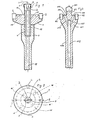
- FIGS. 1 and 2 The embodiment of a rock boring tool shown in FIGS. 1 and 2 has a tool body which consists of a carrier for cutting bodies 2 formed as a circular disk 1 and a centering pin 3, the shaft 4 of which has an external thread 5.
- the support disc 1 is provided with a central threaded bore for the external thread 5 of the centering pin 3.
- a tool shaft 6 is screwed onto this projecting end of the shaft 4.
- a cutting body 7 is fastened in a diametrical slot, the cutting edge 8 of which forms the tip 9 of the centering pin 3.
- the end face 11 of the carrier disk 1 facing the tip 9 is flat.
- the cutting body 2 are arranged at a radial distance from the centering pin 3, so that between the cutting body 7 of the centering pin and the cutting body 2 of the carrier disk 1 a part which is unprocessed when drilling through the cutting tools remains free from the flat end face 11 through the Stroke movement of the Tool is smashed.
- the tool shank 6 and the centering pin 3 are provided with axial bores 12 and 13 which are aligned with one another when the tool is screwed together.
- the bore 13 of the centering pin is designed as a blind hole and is connected by a branch hole, not shown in the drawing, to an opening which is arranged at the free end of the centering pin 3.
- the part of the centering pin 3 protruding from the end face 11 is so long that the mouth opening 14 is at an axial distance in front of the cutting edges of the cutting bodies 2. It is thereby achieved that the drilling dust upstream of the end face 11 only during drilling. can get through the annular space to the mouth opening 14 which surrounds the centering pin 3 during drilling. This creates the possibility of preventing the mouth opening 14 from becoming blocked.
- the part of the carrier disk 1 which is adjacent to the tip 9 of the centering pin 3 is cylindrical, as can be seen in FIG. 1, so that an annular space is formed during drilling between this cylindrical peripheral surface of the carrier disk 1 and the inner wall of the bore produced by the drilling tool, its radial Dimension by the radial projection of the cutting body 2 is precisely defined over this cylindrical peripheral surface.
- This can be provided in the construction of the tool that this Annulus is so narrow that the air sucked in through the orifices 7 in the annulus has such a high speed that even when drilling upwards it can be avoided with certainty that drilling dust can fall down through the annulus.
- the carrier disk 1 in the embodiment shown in FIG. 1 is limited only by two flat end faces and / a cylindrical and frustoconical peripheral surface, the carrier disk can be produced with an extremely low amount of work.
- the formation of the carrier disk can also be simplified even further by omitting the frustoconical peripheral surface without significantly impairing the tool.
- a circumferential groove 15 is provided in the annular surface which is left free in the front view according to FIG can. Additional teeth 16 can be provided in addition to the centering pin 3.
- the carrier disk 101, the centering pin 102 and the tool shank 104 are produced in one piece.
- the cutting bodies 102 and 107 are in this case fastened to the carrier disk 101 or to the centering pin 102 in the same manner as in the previously described exemplary embodiment.
- the suction channel consists only of a blind bore 112 which projects through the tool shank 104 into the carrier disk 101 and is connected there by branch bores 117 to outlet openings 114 which are arranged in the flat end face 111 of the carrier disk 101.
Abstract
Ein Gesteinsbohrer mit einem Zentrierzapfen (3), mit hinter seiner Spitze und um ihn herum angeordneten Schneidkörper (2), die an einer kreisförmigen Scheibe (1) befestigt sind, und mit einem Absaugkanal (12) zum Absaugen des Bohrmehls.A rock drill with a centering pin (3), with cutting bodies (2) arranged behind and around it, which are fastened to a circular disc (1), and with a suction channel (12) for suctioning off the drilling dust.
Description
Die Erfindung betrifft ein Gesteinsbohrwerkzeug mit den im Oberbegriff des Anspruches 1 angeführten Merkmalen.The invention relates to a rock drilling tool with the features stated in the preamble of claim 1.
Gesteinsbohrwerkzeuge dieser Art sind als sogenannte Kreuzschlagbohrer bekannt. Bei diesen bekannten Kreuzschlagbohrern weist der Träger radial vorstehende Arme auf, an deren Enden die Schneidkörper angeordnet sind. In der Regel sind hierbei die Schneidkörper in radialem Abstand von dem Zentrierzapfen angeordnet. Der beim Bohren hierbei weder von der Spitze des Zentrierzapfens noch von den Schneidkörpern zerkleinerte Ring wird. durch das Aufschlagen der von den Trägerarmen gebildeten Schultern zertrümmert. Das hierbei anfallende zum Teil sehr grobkör- nige Bohrmehl tritt teilweise in die Zwischenräume zwischen .den Trägerarmen, so daß es beim Bohren in einer Decke durch diese Zwischenräume nach unten in das Gesicht der die Bohrmaschine haltenden Person fällt. Beim Bohren in einer nach unten gerichteten Richtung dämpft das Bohrmehl den Aufschlag des Bohrwerkzeuges auf das Ende der Bohrung, so daß dadurch die Bohrleistung beeinträchtigt wird. Auch ist die Herstellung des mit radial vorstehenden Armen versehenen Trägers verhältnismäßig aufwendig.Rock drilling tools of this type are known as so-called cross impact drills. In these known cross impact drills, the carrier has radially projecting arms, at the ends of which the cutting bodies are arranged. As a rule, the cutting bodies are arranged at a radial distance from the centering pin. The ring that is not crushed by the tip of the centering pin or the cutting elements during drilling. by hitting the shoulders formed by the support arms wrecked. The thus arising some very coarse-ni e g drilling dust occurs partially in the intermediate spaces between .the support arms, so that it falls into the face of the person holding the drilling machine during drilling in a ceiling through these gaps down. When drilling in a downward direction, the drilling dust dampens the impact of the drilling tool on the end of the hole, so that the drilling performance is impaired. The manufacture of the carrier provided with radially projecting arms is also relatively complex.
Der Erfindung liegt die Aufgabe zugrunde, ein Gesteinsbohrwerkzeug mit um einen Zentrierzapfen angeordneten Schneidkörpern zu schaffen, das einfacher herstellbar ist und eine bessere Bohrleistung aufweist als die bekannten Kreuzschlagbohrer und durch das beim Bohren die die Bohrarbeit ausführende Person nicht vom Bohrmehl belästigt wird.The invention has for its object to provide a rock drilling tool with arranged around a centering pin, which is easier to manufacture and has a better drilling performance than the known cross impact drill and by drilling the person performing the drilling work is not bothered by the drilling dust.
Diese Aufgabe ist gemäß der Erfindung durch das Gesteinsbohrwerkzeug gemäß dem Anspruch 1 gelöst. Dadurch, daß der Träger für den Schneidkörper als kreisförmige Scheibe ausgebildet ist, entsteht beim Bohren zwischen der Trägerscheibe und der Bohrungswand lediglich ein sehr enger Zwischenraum. Erst dieser enge Zwischenraum macht es sinnvoll, beim Werkzeugkörper einen Absaugkanal zum Absaugen des Bohrmehls vorzusehen, da dadurch gewährleistet ist; daß die beim Absaugen entstehende Luftströmungen dem engen Zwischenraum eine ausreichende Geschwindigkeit besitzt, um zu verhindern, daß Bohrmehl in diesen Zwischenraum eintritt. Durch die Ausbildung des Trägers als Scheibe wird gleichzeitig erreicht, daß die ganze, der Spitze des Zentrierzapfens zugekehrte Stirnfläche zum Zertrümmern des Bohrmehls beiträgt, so daß gewährleistet ist, daß das Bohrmehl so fein zertrümmert wird, daß es in vollem Umfang durch den Absaugkanal abgesaugt werden kann. Durch die ständige Absaugung des Bohrmehls wird darüber hinaus erreicht, daß die feinen Bohrmehlbestandteile nicht ein Polster bilden können, das bei dem bekannten Kreuzschlagbohrer beim Bohren nach unten die Schlagenergie des Kreizschlagbohrers dämpft. Auch wird durch den Absaugvorgang das feine Bohrmehl beim Gesteinsbohrwerkzeug gemäß der Erfindung in jedem Fall schneller abgeführt als bei dem bekannten Kreuzschlagbohrer, so daβ sich insgesant eine wesentlich bessere Bahrleistung ergibt. Dadurch, daß beim Herstellen des Werkzeugkörpers. lediglich eine runde Scheibe hergestellt werden muß, wird der Herstellungsaufwand gegenüber den bekannten Kreuzschlagbohrern wesentlich verringert. Auch hat der Werkzeugkörper des erfindungsgemäßen Gesteinsbohrwerkzeuges eine wesentlich größere Festigkeit, so daß er bei gleicher Festigkeit wie ein Kreuzbohrwerkzeug mit geringerem Gewicht herstellbar ist, wodurch die übertragung der Schlagenergie verbessert wird, was wiederum zur Steigerung der Bohrleistung beiträgt.This object is achieved according to the invention by the rock drilling tool according to claim 1. The fact that the carrier for the cutting body is designed as a circular disk, there is only a very narrow gap when drilling between the carrier disk and the bore wall. Only this narrow space makes it useful to provide a suction channel for the drilling dust in the tool body, since this ensures that; that the air currents arising during suction have a sufficient speed in the narrow space to prevent drilling dust from entering this space. The design of the carrier as a disc also ensures that the entire end face facing the tip of the centering pin contributes to the shattering of the drilling dust, so that it is ensured that the drilling dust is crushed so finely that it is sucked off completely through the suction channel can. Due to the constant suction of the drilling dust is above also achieved that the fine drilling dust components can not form a cushion that dampens the impact energy of the circular impact drill when drilling down in the known cross impact drill. Also, the fine drilling dust in the rock drilling tool according to the invention is in any case removed more quickly than in the known cross impact drill by the suction process, so that overall a much better driving performance results. The fact that when manufacturing the tool body. only a round disc has to be produced, the manufacturing effort compared to the known cross impact drill is significantly reduced. The tool body of the rock drilling tool according to the invention also has a much greater strength, so that it can be produced with the same strength as a cross drilling tool with a lower weight, which improves the transmission of the impact energy, which in turn contributes to increasing the drilling performance.
Um die oben genannten Vorteile optimal ausnutzen zu können, ist bei einer vorteilhaften Ausführungsform der Erfindung die der Spitze des Zentrierzapfens zugekehrte Stirnfläche der Trägerscheibe im wesentlichen eben. Um jedoch hierbei das Entstehen von Rissen durch beim Nachschleifen der Schneidkörper verursachte Schleifspuren zu vermeiden, kann in der Stirnfläche der Trägerscheibe zwischen dem Zentrierzapfen und den Schneidkörpern eine umlaufende Ringnut vorhanden sein.In order to be able to optimally utilize the advantages mentioned above, in an advantageous embodiment of the invention the end face of the carrier disk facing the tip of the centering pin is essentially flat. However, in order to avoid the formation of cracks due to grinding marks caused by regrinding of the cutting bodies, a circumferential annular groove can be present in the end face of the carrier disk between the centering pin and the cutting bodies.
Die den Absaugkanal mit der Bohrstelle verbindende Mündungsöffnung des Absaugkanals kann auf der der Spitze des Zentrierzapfens zugekehrten Seite des Werkzeugkörpers an einer beliebigen Stelle angeordnet sein. Bei der bevorzugten Ausführungsform der Erfindung ist die Mündungsöffnung im freien Ende des Zentrierzapfens und in einem axialen Abstand vor den Schneiden der an der Trägerscheibe befestigten Schneidkörper angeordnet. Dadurch wird erreicht, daß das Bohrmehl an der Spitze des Zentrierzapfens sicher abgesaugt wird und daß der Zwischenraum zwischen dem Zentrierzapfen und der von diesem erzeugten Bohrung durch den Überstand des an der Spitze des Zentrierzapfens befestigten Schneidkörpers über der zylindrischen Umfangsfläche des Zentrierzapfens so eng ausgebildet werden kann, daß die Mündungsöffnung des Absaugkanals nur von Bohrkleinpartikeln erreicht werden kann, die ohne Verstopfungsgefahr in die Mündungsöffnung des Absaugkanals eingesaugt werden können. Weitere vorteilhafte Merkmale sind in den Ansprüchen und in der folgenden Beschreibung von Ausführungsbeispielen angegeben, die die Erfindung anhand der Zeichnung im einzelnen erläutert.The mouth opening of the suction channel connecting the suction channel to the drilling point can be arranged at any point on the side of the tool body facing the tip of the centering pin. In the preferred embodiment of the invention, the mouth opening is arranged in the free end of the centering pin and at an axial distance in front of the cutting edges of the cutting bodies fastened to the carrier disk. This ensures that the drilling dust at the tip of the centering pin is suctioned off safely and that the space between the centering pin and the bore produced by it can be formed so narrowly by the projection of the cutting body fastened to the tip of the centering pin over the cylindrical peripheral surface of the centering pin that the opening of the suction channel can only be reached by small cuttings which can be sucked into the mouth of the suction channel without risk of clogging. Further advantageous features are specified in the claims and in the following description of exemplary embodiments which explain the invention in detail with reference to the drawing.
Es zeigen:
- eines Fig. 1 einen Axialschnitt / ersten Ausführungsbeispiels, wobei eine Modifikation desselben gestrichelt angedeutet ist;
- Fig. 2 eine von der Spitze des Zentrierzapfens aus gesehene Stirnansicht des Ausführungsbeispieles nach Fig. 1;
- Fig. 3 einen der Fig. 1 entsprechenden Schnitt eines zweiten Ausführungsbeispieles.
- 1 shows an axial section / first exemplary embodiment, a modification of the same being indicated by dashed lines;
- FIG. 2 shows an end view of the exemplary embodiment according to FIG. 1 seen from the tip of the centering pin; FIG.
- Fig. 3 shows a section corresponding to Fig. 1 of a second embodiment.
Das in den Figuren 1 und 2 dargestellte Ausführungsbeispiel eines Gesteinsbohiwerkzeuges weist einen Werkzeugkörper auf, der aus einem als kreisförmige Scheibe 1 gebildeten Träger für Schneidkörper 2 und einem Zentrierzapfen 3 besteht, dessen Schaft 4 ein Außengewinde 5 aufweist. Die Tragscheibe 1 ist mit'einer zentralen Gewindebohrung für das Außengewinde 5 des Zentrierzapfens 3 versehen. Auf der den Schneidkörpern 2 abgekehrten Stirnseite der Trägerscheibe 1 ragt in zusammengeschraubtem Zustand der Schaft 4 heraus. Auf dieses herausragende Ende des Schaftes 4 ist ein Werkzeugschaft 6 aufgeschraubt. Am freien Ende des Zentrierzapfens 3 ist in einem Diametralschlitz ein Schneidkörper 7 befestigt, dessen Schneide 8 die Spitze 9 des Zentrierzapfens 3 bildet. Die der Spitze 9 zugekehrte Stirnseite 11 der Trägerscheibe 1 ist eben. Die Schneidkörper 2 sind hierbei in einem radialen Abstand von dem Zentrierzapfen 3 angeordnet, so daß zwischen dem Schneidenkörper 7 des Zentrierzapfens und den Schneid körpern 2 der Trägerscheibe 1 ein beim Bohren durch die Schneidwerkzeuge unbearbeiteter Teil frei bleibt, der von der ebenen Stirnfläche 11 durch die Schlagbewegung des Werkzeuges zertrümmert wird.The embodiment of a rock boring tool shown in FIGS. 1 and 2 has a tool body which consists of a carrier for
Der Werkzeugschaft 6 und der Zentrierzapfen 3 sind mit axialen Bohrungen 12 bzw. 13 versehen, die im zusammengeschraubten Zustand des Werkzeuges miteinander fluchten. Die Bohrung 13 des Zentrierzapfens ist als Sackbohrung ausgeführt und durch eine, in der Zeichnung nicht dargestellte Abzweigbohrung mit einer Mündungsöffnung, die am freien Ende des Zentrierzapfens 3 angeordnet ist, verbunden. Der aus der Stirnfläche 11 herausragende Teil des Zentrierzapfens 3 ist so lang, daß sich die Mündungsöffnung 14 in einem axialen Abstand vor den Schneiden der Schneidkörper 2 befindet. Dadurch wird erreicht, daß beim Bohren das. der Stirnfläche 11 vorgelagerte Bohrmehl nur. durch den Ringraum an die Mündungsöffnung 14 gelangen kann, der den Zentrierzapfen 3 beim Bohren umgibt. Dies schafft die Möglichkeit, ein Verstopfen der Mündungsöffnung 14 zu verhindern. Dies wird dadurch erreicht, daß der Schneidkörper 7 aus der zylindrischen Umfangsfläche des Zentrierzapfens 3 nur um eine in der radialen Richtung gemessene Länge herausragt, die kleiner ist als die größte lichte Weite der Mündungsöffnung 14 des Absaugkanals 12, 13. Die beim Bohren vor der Stirnfläche 11 zerkleinerten Partikel des Bohrmehls können also durch den Ringraum um den Zentrierzapfen 3 in die Mündungsöffnung 14 nur dann angesaugt werden, wenn sie.so klein sind, daß sie die Mündungsöffnung 14 mit Sicherheit nicht mehr verstopfen können.The
Der der Spitze 9 des Zentrierzapfens 3 benachbarte Teil der Trägerscheibe 1 ist, wie das aus Figur 1 ersichtlich ist, zylindrisch ausgebildet, so daß beim Bohren zwischen dieser zylindrischen Umfangsfläche der Trägerscheibe 1 und der Innenwand der vom Bohrwerkzeug erzeugten Bohrung ein Ringraum entsteht, dessen radiale Abmessung durch den radialen überstand der Schneidkörper 2 über diese zylindrische Umfangsfläche genau definiert ist. Dadurch kann bei der Konstruktion des Werkzeuges vorgesehen werden, daß dieser Ringraum so eng ist, daß die durch die Mündungsöffnungen 7 angesaugte Luft im Ringraum eine so große Geschwindigkeit hat, daß auch beim Bohren nach oben mit Sicherheit vermieden werden kann, daß Bohrmehl durch den Ringraum nach unten fallen kann.The part of the carrier disk 1 which is adjacent to the tip 9 of the
Dadurch, daß die Trägerscheibe 1 bei dem in Figur 1 dargestellten Ausführungsbeispiel nur von zwei ebenen Stirn- flächen und/einer zylindrischen und kegelstumpfförmigen Umfangsfläche begrenzt ist, ist die Trägerscheibe mit einem außerordentlich geringen Arbeitsaufwand herstellbar. Hierbei kann die Ausbildung der Trägerscheibe auch noch durch Weglassung der kegelstumpfförmigen Umfangsfläche noch weiter vereinfacht werden, ohne das Werkzeug wesentlich zu beeinträchtigen.Due to the fact that the carrier disk 1 in the embodiment shown in FIG. 1 is limited only by two flat end faces and / a cylindrical and frustoconical peripheral surface, the carrier disk can be produced with an extremely low amount of work. Here, the formation of the carrier disk can also be simplified even further by omitting the frustoconical peripheral surface without significantly impairing the tool.
Bei einer in den Figuren 1 und 2 gestrichelt angedeuteten Abwandlung dieses Ausführungsbeispieles ist in der in der Stirnansicht nach Figur 2 zwischen den Schneiden der Schneidkörper 2 und 9 freibleibenden Ringfläche eine umlaufende Nut 15 vorgesehen, in der zwei einander diametral gegenüberliegende Hartmetallzähne 16 oder Hartmetallstifte angeordnet sein können. Weitere Zähne 16 können neben dem Zentrierzapfen 3 vorgesehen sein.In a modification of this exemplary embodiment indicated by dashed lines in FIGS. 1 and 2, a
Bei dem in Figur 3 dargestellten Ausführungsbeispiel sind die Trägerscheibe 101, der Zentrierzapfen 102 und der Werkzeugschaft 104 in einem Stück hergestellt. Die Schneidkörper 102 und 107 sind hierbei an der Trägerscheibe 101 bzw. an dem Zentrierzapfen 102 in der gleichen Weise befestigt wie beim vorher beschriebenen Ausführungsbeispiel. Der Absaugkanal besteht bei diesem Ausführungsbeispiel nur aus einer Sackbohrung 112, die durch den Werkzeugschaft 104 bis in die Trägerscheibe 101 hineinragt und dort durch Abzweigbohrungen 117 mit Mündungsöffnungen 114 verbunden ist, die in der ebenen Stirnfläche 111 der Trägerscheibe 101 angeordnet sind. Damit diese Mündungsöffnungen 114 durch das Bohrmehl nicht verstopfen können, ist nicht nur der Überstand, um den der an der Spitze des Zentrierzapfens 103 befestigte Schneidkörper 107 aus der zylindrischen Umfangsfläche des Zentrierzapfens 103 herausragt, sondern auch der überstand, um den die Schneiden der an der Trägerscheibe befestigten Schneidkörper 102 über der Stirnfläche 111 axial vorstehen, kleiner als die größte lichte Weite der Mündungsöffnungen 114.In the exemplary embodiment shown in FIG. 3, the
Claims (10)
Applications Claiming Priority (2)
| Application Number | Priority Date | Filing Date | Title |
|---|---|---|---|
| DE2807156A DE2807156C2 (en) | 1978-02-20 | 1978-02-20 | Rock drilling tool |
| DE2807156 | 1978-02-20 |
Publications (2)
| Publication Number | Publication Date |
|---|---|
| EP0003816A1 true EP0003816A1 (en) | 1979-09-05 |
| EP0003816B1 EP0003816B1 (en) | 1981-06-17 |
Family
ID=6032443
Family Applications (1)
| Application Number | Title | Priority Date | Filing Date |
|---|---|---|---|
| EP79100476A Expired EP0003816B1 (en) | 1978-02-20 | 1979-02-19 | Rock drilling tool |
Country Status (3)
| Country | Link |
|---|---|
| US (1) | US4275796A (en) |
| EP (1) | EP0003816B1 (en) |
| DE (1) | DE2807156C2 (en) |
Cited By (1)
| Publication number | Priority date | Publication date | Assignee | Title |
|---|---|---|---|---|
| GB2195564A (en) * | 1986-10-11 | 1988-04-13 | George Waddell | Piloted drill tip |
Families Citing this family (13)
| Publication number | Priority date | Publication date | Assignee | Title |
|---|---|---|---|---|
| DE8623584U1 (en) * | 1986-09-03 | 1986-10-16 | Töpfer, Rainer, 2802 Ottersberg | Drilling tool |
| SE507665C2 (en) * | 1994-02-02 | 1998-06-29 | Disab Vacuum Technology Ab | Device, method and drill head for dry full-area drilling |
| DE4420398A1 (en) * | 1994-06-08 | 1995-12-14 | Herwig Bohrtechnik Schmalkalde | Combination cutting tool used for machining stone |
| US5641027A (en) * | 1995-01-09 | 1997-06-24 | Utd Incorporated | Drilling system |
| US5732784A (en) * | 1996-07-25 | 1998-03-31 | Nelson; Jack R. | Cutting means for drag drill bits |
| SE514113C2 (en) | 1998-03-23 | 2001-01-08 | Sandvik Ab | Rock drilling tools for striking drilling and holders designed to be included in the tool |
| DE10117262A1 (en) * | 2001-01-17 | 2002-07-18 | Hilti Ag | Rock drill has head with main and subsidiary blades, curved and diametrically opposite cutting edges, and point |
| US7673706B2 (en) * | 2006-03-30 | 2010-03-09 | Sandvik Intellectual Property Ab | Down-the-hole hammer with pilot and method of enlarging a hole |
| CA2645897A1 (en) * | 2006-03-30 | 2007-10-11 | Sandvik Intellectual Property Ab | Down-the-hole hammer, percussion bit assembly and method of enlarging a hole |
| US7674078B1 (en) * | 2006-07-28 | 2010-03-09 | Mirko Buzdum | Hole saw having efficient slug removal |
| US10385620B2 (en) | 2016-05-17 | 2019-08-20 | Ajax Tool Works, Inc. | Rotary percussive piloted rock drill bit |
| US10047564B2 (en) | 2016-05-17 | 2018-08-14 | Ajax Tool Works, Inc. | Rotary percussive piloted rock drill bit |
| CN109441358A (en) * | 2018-10-30 | 2019-03-08 | 龙在云 | A kind of rotary swing arm abrasive drill structure |
Citations (7)
| Publication number | Priority date | Publication date | Assignee | Title |
|---|---|---|---|---|
| DE7040363U (en) * | Motoren- Und Turbinen-Union Friedrichshafen Gmbh | Drill head | ||
| DE914723C (en) * | 1949-02-03 | 1954-07-08 | Wallram Hartmetall | Drills for rock drilling machines |
| US2803153A (en) * | 1956-07-27 | 1957-08-20 | Erwood Inc | Adjustable saw and planer |
| US3145789A (en) * | 1962-03-20 | 1964-08-25 | Russell H Lawry | Pilot rock drill |
| CH436926A (en) * | 1962-05-12 | 1967-05-31 | Cuttahead Company Limited | Knife head |
| DE7026751U (en) * | 1970-07-16 | 1970-10-15 | Karnebogen Richard | IMPACT DRILL BIT FOR DRILLING STONE AND THE LIKE. |
| DE2645693A1 (en) * | 1976-10-09 | 1978-04-13 | Bosch Gmbh Robert | Rock drill with sleeve on shank - has open forward end and connected to transverse passage at rear |
Family Cites Families (9)
| Publication number | Priority date | Publication date | Assignee | Title |
|---|---|---|---|---|
| US1351003A (en) * | 1919-07-19 | 1920-08-24 | Acme Oil & Drill Co Inc | Well-drilling bit for oil, water, or gas |
| GB456140A (en) * | 1934-05-29 | 1936-11-03 | Chicago Pneumatic Tool Co | Rotary drilling bit |
| US2759705A (en) * | 1951-05-01 | 1956-08-21 | Bjorkman Gustaf Erik | Rock drills with inserted cutting edges |
| FR74109E (en) * | 1958-08-19 | 1960-11-07 | J K Smit & Fils Ets | Improvements to diamond drill heads |
| US3321034A (en) * | 1965-01-19 | 1967-05-23 | James E Webb | Sample collecting impact bit |
| US3469641A (en) * | 1967-12-11 | 1969-09-30 | Cominco Ltd | Reaming bit assembly |
| DE2414354A1 (en) * | 1974-03-26 | 1975-10-16 | Heller Geb | ROCK DRILLS |
| DE2510265A1 (en) * | 1975-03-08 | 1976-09-16 | Richard Karnebogen | Drilling bit for masonry drilling machine - has central conical convex cutting surface with hard metal inserts |
| DE2602238A1 (en) * | 1976-01-22 | 1977-08-04 | Bosch Gmbh Robert | DRILL BIT |
-
1978
- 1978-02-20 DE DE2807156A patent/DE2807156C2/en not_active Expired
-
1979
- 1979-02-15 US US06/012,576 patent/US4275796A/en not_active Expired - Lifetime
- 1979-02-19 EP EP79100476A patent/EP0003816B1/en not_active Expired
Patent Citations (7)
| Publication number | Priority date | Publication date | Assignee | Title |
|---|---|---|---|---|
| DE7040363U (en) * | Motoren- Und Turbinen-Union Friedrichshafen Gmbh | Drill head | ||
| DE914723C (en) * | 1949-02-03 | 1954-07-08 | Wallram Hartmetall | Drills for rock drilling machines |
| US2803153A (en) * | 1956-07-27 | 1957-08-20 | Erwood Inc | Adjustable saw and planer |
| US3145789A (en) * | 1962-03-20 | 1964-08-25 | Russell H Lawry | Pilot rock drill |
| CH436926A (en) * | 1962-05-12 | 1967-05-31 | Cuttahead Company Limited | Knife head |
| DE7026751U (en) * | 1970-07-16 | 1970-10-15 | Karnebogen Richard | IMPACT DRILL BIT FOR DRILLING STONE AND THE LIKE. |
| DE2645693A1 (en) * | 1976-10-09 | 1978-04-13 | Bosch Gmbh Robert | Rock drill with sleeve on shank - has open forward end and connected to transverse passage at rear |
Cited By (2)
| Publication number | Priority date | Publication date | Assignee | Title |
|---|---|---|---|---|
| GB2195564A (en) * | 1986-10-11 | 1988-04-13 | George Waddell | Piloted drill tip |
| GB2195564B (en) * | 1986-10-11 | 1991-03-27 | George Waddell | Piloted drill bit. |
Also Published As
| Publication number | Publication date |
|---|---|
| US4275796A (en) | 1981-06-30 |
| EP0003816B1 (en) | 1981-06-17 |
| DE2807156C2 (en) | 1986-11-20 |
| DE2807156A1 (en) | 1979-08-23 |
Similar Documents
| Publication | Publication Date | Title |
|---|---|---|
| DE2945766C2 (en) | Drill bit and drill tool with such a drill bit | |
| DE3339211C2 (en) | ||
| EP0151251B1 (en) | Drill having a plurality of cutting edges | |
| DE10207257B4 (en) | Rotary cutting tool with exchangeable cutting insert | |
| DE60131780T2 (en) | TOOL AND CUTTER FOR DISCONTINUED WORK | |
| DE102012212146B4 (en) | Coupling point for a modular rotary tool and tool head and carrier for such a modular rotary tool | |
| EP0003816B1 (en) | Rock drilling tool | |
| DE2709830C3 (en) | Center drill for processing wood, plastic and the like. | |
| CH616355A5 (en) | ||
| DE3031216C2 (en) | Chuck for taps | |
| DE2832653B2 (en) | Ball finger milling cutter | |
| DE102015220777B4 (en) | Tool coupling between two coupling parts as well as coupling part for such a tool coupling | |
| DE19942987A1 (en) | Drilling tool | |
| DE2528003A1 (en) | ROCK DRILLS | |
| DE102020102979B4 (en) | chamfering tool | |
| EP0489410B1 (en) | Device for sharpening drill bits | |
| DE3705717A1 (en) | Box countersink or hollow drill bit and production process for this | |
| CH652446A5 (en) | Core cutter | |
| DE4000402C2 (en) | ||
| DE202005020931U1 (en) | Drill for metal work materials comprises a cutter which is soldered to the face of the drill shank with a star-shaped toothing | |
| EP0258660B1 (en) | Single-lip solid drill | |
| DE2919074C2 (en) | ||
| DE10059969A1 (en) | Sawing tool for a handheld circular saw | |
| DE3346440C2 (en) | Drill chucks, in particular hammer drill chucks | |
| DE2948665A1 (en) | Hammer-drill with central exhaust passage - has two diametrically-opposite suction passages in shank behind hardened insert |
Legal Events
| Date | Code | Title | Description |
|---|---|---|---|
| PUAI | Public reference made under article 153(3) epc to a published international application that has entered the european phase |
Free format text: ORIGINAL CODE: 0009012 |
|
| AK | Designated contracting states |
Designated state(s): BE CH FR GB NL SE |
|
| 17P | Request for examination filed | ||
| GRAA | (expected) grant |
Free format text: ORIGINAL CODE: 0009210 |
|
| AK | Designated contracting states |
Designated state(s): BE CH FR GB NL SE |
|
| PGFP | Annual fee paid to national office [announced via postgrant information from national office to epo] |
Ref country code: FR Payment date: 19820224 Year of fee payment: 4 |
|
| PGFP | Annual fee paid to national office [announced via postgrant information from national office to epo] |
Ref country code: NL Payment date: 19820228 Year of fee payment: 4 |
|
| PLBI | Opposition filed |
Free format text: ORIGINAL CODE: 0009260 |
|
| PLBI | Opposition filed |
Free format text: ORIGINAL CODE: 0009260 |
|
| PGFP | Annual fee paid to national office [announced via postgrant information from national office to epo] |
Ref country code: CH Payment date: 19820331 Year of fee payment: 4 Ref country code: BE Payment date: 19820331 Year of fee payment: 4 |
|
| 26 | Opposition filed |
Opponent name: SANDVIK AKTIEBOLAG Effective date: 19820311 |
|
| 26 | Opposition filed |
Opponent name: VEREINIGTE EDELSTAHLWERKE AKTIENGESELLSCHAFT (VEW) Effective date: 19820316 |
|
| PLAB | Opposition data, opponent's data or that of the opponent's representative modified |
Free format text: ORIGINAL CODE: 0009299OPPO |
|
| PLBG | Opposition deemed not to have been filed |
Free format text: ORIGINAL CODE: 0009274 |
|
| R26 | Opposition filed (corrected) |
Opponent name: SANDVIK AKTIEBOLAG * 820316 VEREINIGTE EDELSTAHLWE Effective date: 19820311 |
|
| 26D | Opposition deemed not to have been filed |
Opponent name: SANDVIK AKTIEBOLAG Effective date: 19820701 |
|
| PG25 | Lapsed in a contracting state [announced via postgrant information from national office to epo] |
Ref country code: GB Effective date: 19830219 Ref country code: BE Effective date: 19830219 |
|
| PG25 | Lapsed in a contracting state [announced via postgrant information from national office to epo] |
Ref country code: NL Effective date: 19830901 |
|
| GBPC | Gb: european patent ceased through non-payment of renewal fee | ||
| NLV4 | Nl: lapsed or anulled due to non-payment of the annual fee | ||
| PG25 | Lapsed in a contracting state [announced via postgrant information from national office to epo] |
Ref country code: FR Free format text: LAPSE BECAUSE OF NON-PAYMENT OF DUE FEES Effective date: 19831031 |
|
| REG | Reference to a national code |
Ref country code: CH Ref legal event code: PL |
|
| REG | Reference to a national code |
Ref country code: FR Ref legal event code: ST |
|
| PGFP | Annual fee paid to national office [announced via postgrant information from national office to epo] |
Ref country code: SE Payment date: 19840331 Year of fee payment: 6 |
|
| RDAG | Patent revoked |
Free format text: ORIGINAL CODE: 0009271 |
|
| STAA | Information on the status of an ep patent application or granted ep patent |
Free format text: STATUS: PATENT REVOKED |
|
| 27W | Patent revoked |
Effective date: 19870126 |
|
| EUG | Se: european patent has lapsed |
Ref document number: 79100476.5 Effective date: 19880215 |
|
| APAC | Appeal dossier modified |
Free format text: ORIGINAL CODE: EPIDOS NOAPO |
|
| APAC | Appeal dossier modified |
Free format text: ORIGINAL CODE: EPIDOS NOAPO |
|
| PLAB | Opposition data, opponent's data or that of the opponent's representative modified |
Free format text: ORIGINAL CODE: 0009299OPPO |