EP0001046B1 - Dispositif pour étancher des joints entre des éléments de construction, de préférence entre des éléments de cuvelage en béton armé - Google Patents
Dispositif pour étancher des joints entre des éléments de construction, de préférence entre des éléments de cuvelage en béton armé Download PDFInfo
- Publication number
- EP0001046B1 EP0001046B1 EP78100582A EP78100582A EP0001046B1 EP 0001046 B1 EP0001046 B1 EP 0001046B1 EP 78100582 A EP78100582 A EP 78100582A EP 78100582 A EP78100582 A EP 78100582A EP 0001046 B1 EP0001046 B1 EP 0001046B1
- Authority
- EP
- European Patent Office
- Prior art keywords
- groove
- strip
- pressure transmitting
- jointing
- tape
- Prior art date
- Legal status (The legal status is an assumption and is not a legal conclusion. Google has not performed a legal analysis and makes no representation as to the accuracy of the status listed.)
- Expired
Links
- 239000011150 reinforced concrete Substances 0.000 title claims description 9
- 238000007789 sealing Methods 0.000 title description 20
- 238000010276 construction Methods 0.000 title description 2
- 229910000831 Steel Inorganic materials 0.000 claims description 3
- 239000010959 steel Substances 0.000 claims description 3
- 238000005065 mining Methods 0.000 claims description 2
- 230000005540 biological transmission Effects 0.000 description 27
- 230000006835 compression Effects 0.000 description 6
- 238000007906 compression Methods 0.000 description 6
- XLYOFNOQVPJJNP-UHFFFAOYSA-N water Substances O XLYOFNOQVPJJNP-UHFFFAOYSA-N 0.000 description 6
- UQMRAFJOBWOFNS-UHFFFAOYSA-N butyl 2-(2,4-dichlorophenoxy)acetate Chemical compound CCCCOC(=O)COC1=CC=C(Cl)C=C1Cl UQMRAFJOBWOFNS-UHFFFAOYSA-N 0.000 description 5
- 238000005452 bending Methods 0.000 description 4
- 239000004567 concrete Substances 0.000 description 4
- 230000000694 effects Effects 0.000 description 4
- 239000000463 material Substances 0.000 description 4
- 239000000853 adhesive Substances 0.000 description 2
- 230000001070 adhesive effect Effects 0.000 description 2
- RHZUVFJBSILHOK-UHFFFAOYSA-N anthracen-1-ylmethanolate Chemical compound C1=CC=C2C=C3C(C[O-])=CC=CC3=CC2=C1 RHZUVFJBSILHOK-UHFFFAOYSA-N 0.000 description 2
- 239000003830 anthracite Substances 0.000 description 2
- 239000000428 dust Substances 0.000 description 2
- 229920001038 ethylene copolymer Polymers 0.000 description 2
- 238000009434 installation Methods 0.000 description 2
- 230000001960 triggered effect Effects 0.000 description 2
- 239000004698 Polyethylene Substances 0.000 description 1
- 229920006328 Styrofoam Polymers 0.000 description 1
- 239000010426 asphalt Substances 0.000 description 1
- 238000009435 building construction Methods 0.000 description 1
- 230000008602 contraction Effects 0.000 description 1
- 238000005260 corrosion Methods 0.000 description 1
- 230000007797 corrosion Effects 0.000 description 1
- 238000005336 cracking Methods 0.000 description 1
- 238000009415 formwork Methods 0.000 description 1
- 239000007788 liquid Substances 0.000 description 1
- 239000012528 membrane Substances 0.000 description 1
- 239000002184 metal Substances 0.000 description 1
- 238000000034 method Methods 0.000 description 1
- 239000000203 mixture Substances 0.000 description 1
- 239000004033 plastic Substances 0.000 description 1
- 229920003023 plastic Polymers 0.000 description 1
- -1 polyethylene Polymers 0.000 description 1
- 229920000573 polyethylene Polymers 0.000 description 1
- 239000003566 sealing material Substances 0.000 description 1
- 238000007493 shaping process Methods 0.000 description 1
- 238000009416 shuttering Methods 0.000 description 1
- 239000008261 styrofoam Substances 0.000 description 1
- 239000006228 supernatant Substances 0.000 description 1
Images


Classifications
-
- E—FIXED CONSTRUCTIONS
- E21—EARTH OR ROCK DRILLING; MINING
- E21D—SHAFTS; TUNNELS; GALLERIES; LARGE UNDERGROUND CHAMBERS
- E21D11/00—Lining tunnels, galleries or other underground cavities, e.g. large underground chambers; Linings therefor; Making such linings in situ, e.g. by assembling
- E21D11/38—Waterproofing; Heat insulating; Soundproofing; Electric insulating
- E21D11/385—Sealing means positioned between adjacent lining members
-
- E—FIXED CONSTRUCTIONS
- E02—HYDRAULIC ENGINEERING; FOUNDATIONS; SOIL SHIFTING
- E02B—HYDRAULIC ENGINEERING
- E02B3/00—Engineering works in connection with control or use of streams, rivers, coasts, or other marine sites; Sealings or joints for engineering works in general
- E02B3/16—Sealings or joints
Definitions
- the invention relates to an arrangement for sealing components in building construction and civil engineering, preferably for reinforced concrete segments of the mining industry, the joint to be sealed being formed by a flat surface and a surface with a preferably rectangular or trapezoidal groove in cross section, into which a viscoelastic joint tape is inserted is, which lies with its side flanks on the groove flanks and interacts with a viscoelastic pressure transmission tape, the joint tape and the pressure transmission tape being supported on one another.
- the prior art includes a proposal (DE-A 25 42 912) for a contact surface seal in which only a one-piece joint tape is realized, the underside of which is assigned to the bottom surface of the groove and whose thickness increases from the center to the edges. wherein the curvature in the middle of the joint tape corresponds approximately to a protrusion of the joint tape beyond the edge of the groove.
- the tape is first pressed onto the bottom of the groove and then further compressed in the manner of a bending spring body by contact pressure. Due to the shape of the joint tape, the compressive forces only make up about 2.8 times the force required to press the joint tape.
- Such a joint tape can be significantly improved by using certain materials.
- Such a material has a high (at 0.50) transverse contraction number. For this reason, high contact pressures in the bearing areas of the groove base produce high lateral strains transversely to the direction of compression, which result.
- Tilting of the segments can only have a minor impact after transfer from the continuous to the beam-like support, because they only slightly reduce the sealing pressure in the area of one groove edge compared to that on the other groove edge.
- the remaining press-in pressures are relatively large because they cannot be distributed evenly over the entire length of the strip, but are centered in the area of the edge lines.
- a high degree of fitting accuracy is required of the joint tape and the groove, which results from the requirement for uniform sealing in several places. In practice, however, this creates considerable difficulties in shaping the grooves and in complying with the tolerances on the joint tape.
- the invention has for its object to carry out the transfer of the contact pressure for better sealing against pressurized water by means of separate construction elements, in order to meet high demands and in particular make no great demands on the accuracy of fit.
- this object is achieved in that the joint tape is corrugated in cross section and wider in the development than the groove and that the pressure transmission tape is fitted into each of these, leaving a gap between its side flanks and the side flanks of the groove.
- the invention has the advantage that the proposed combination of joint tape and pressure transfer tape is technically simple and does not make high demands on the accuracy of fit.
- the two strips can be produced from extruded broad strips which are subsequently machine-cut be put.
- the use of different or appropriately modified materials can already take into account the expediency of making the joint tape comparatively elastic and the pressure transmission tape comparatively stiff.
- the joint tape which is at least approximately rectangular in cross-section in the development, is curved in the manner of a cosine wave with respect to the center of the groove, and in that the cross-section, which is thicker and rectangular in cross section having pressure transmission tape is glued to the apex area of the cosine wave with the joint tape.
- the procedure can be such that the sealing joint tape is first inserted into the groove alone, with the cosine wave touching the floor on the side walls of the groove.
- the side seals of the compressed joint tape which ensure the sealing of the groove, act close to the floor and are therefore tension-friendly for the application in reinforced concrete segments.
- the subsequently installed pressure transmission tape is also inserted into the groove after the two tapes in the contact area have been coated with a special adhesive.
- the ratios are chosen such that the total height of the joint tape and pressure transmission tape measured orthogonal to the bottom surface of the groove is equal to the groove height in the compressed state and that after assembly and before compression the total height is equal to the sum of the Is four times the amplitude of the cosine wave and twice the thickness of the joint tape.
- the compression of the joint tape begins when the segments are pressed together at the membrane apex and proceeds monotonously from there to the side flanks of the groove.
- the pressure transmission belt is only subjected to slight bending and, in the main, compression.
- a bending stress and a compressive stress state are triggered in the joint tape when compressed to the stretched position.
- the latter stems from the fact that the shaft formed by the band, provided the side flanks of the groove are pale, would experience an extension corresponding to the development of its arc length, which is prevented by di abutment pressures which are lined from the side walls.
- the same clearance height is available everywhere between the bottom surface of the groove and the pressure transfer tape, partly above and partly below the joint tape, so that the latter tape and only slightly the pressure transfer tape have to be compressed.
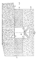
- a circumferential groove 2 is provided in the end faces of a reinforced concrete segment generally denoted by 1.
- the groove has a flat bottom surface 3 and, according to the exemplary embodiment shown in FIG. 1, flat side flanks 4 and 5, so that there is a generally rectangular cross section for the groove.
- a joint tape 7 is used, the cross-section in the development is approximately rectangular. In relation to the center of the groove 2 shown at y, the joint tape is curved in the manner of a cosine wave. The amplitude has the height f. In cross section, the joint tape represents a corrugated sheet lying on the floor 3. That is why its lower edge lies at the apex by a dimension 2 f above the floor 3.
- a pressure transmission belt 8 lies snugly on the joint belt 7. Therefore, its lower edge 9 is 2 f above the compressed joint tape. It must therefore engage in the groove 2 (dimension h) and protrude beyond it by the dimension 2 f. Under these circumstances, the pressure transfer belt 8 disappears completely in the groove 2 when compressed. Consequently, its thickness is h + 2 f.
- the entire sealing body has 4 f + 2 h in the assembled state and 2 f + 2 h in the compressed state.
- the latter dimension corresponds to the depth of the groove.
- the sealing joint tape 7 is first inserted into the groove 2 by itself. This is done so that the cosine wave of the underside 12 of the joint tape 7 on the side walls 4 touches the floor as shown at 15 and 16. In this way, the side flaps of the compressed joint tape, which provide the sealing effect, act close to the floor and are therefore tension-friendly for reinforced concrete tubbing 1. Then the pressure transfer belt 8, which is rectangular in cross section, is inserted into the groove. Before that, the two tapes in the contact area at 17 were coated with a special adhesive and glued. This connection between the two bands 7 and 8, shown at 17, provides an assembly aid.
- the pressure transmission belt 8 should be at least 1 mm narrower than the groove.
- the pressure transmission tape has a thickness (h + f) of 22 mm, which corresponds exactly to the gas total height of the joint tape before installation.
- the pressure transfer belt is therefore flush with the joint surface when the seal has been compressed by 6 mm. This corresponds to a requirement from the segment manufacturers.
- the pressure transfer tape connects, leaving the two gaps S appearing on the side flanks 4 and 5. Without this gap, the transverse expansion of the pressure transmission belt in the compressed state would result in very high compressive stresses in the pressure transmission belt, because in the compressed state a transverse expansion transverse to the y direction is triggered.
- a gap of 0.7 mm is generally sufficient.
- the bond can be limited to a width of about 5 mm.
- the groove 2 has a trapezoidal cross section with flanks 20 and 21 diverging from the inside to the outside.
- the joint tape 7 is curved in a double sinusoidal manner with respect to the center 23 of the groove 2, the two maxima 24 and 25 being symmetrical with respect to one another the center line 23 are arranged.
- the joint tape At the ends 26 and 27, the joint tape in turn rests on the two edge regions 28 and 29 between the side flanks and the bottom surface of the groove.
- the pressure transmission tape 8 is installed, which is left in place with the gap shown at 30 and 31 between its side flanks 32 and the side flanks 20 and 21 of the groove 2.
- the top of the pressure transmission belt is provided with a laminated metal sheet 33.
- the compressed state shown in FIG. 3 essentially corresponds to what has been shown and described in connection with FIG. 1.
- the invention is not restricted to the groove seals of tubbings, which are shown in FIGS. 1-3. In general, it is applicable to design cases in which one structural element has to be sealed against another or entire structures against a floor slab or a foundation. Also, the design of the groove does not play a decisive role with regard to the outline of the structure. H. rectangular floor plans are not a requirement. Circular and differently curved floor plans can also be mastered.
- the supernatants will generally be larger than those at Tübbingen.
- FIGS. 4 and 5 are concerned is a circular clean water tank, the tank shell is designated 40.
- a roof shell 41 is supported on the upper side of the container shell 40 and, apart from wind forces, should not exert any horizontal thrusts on the container shell 40. This requirement arises from the fact that the pure water tank should only be subjected to loads from the water pressure in the radial direction. On the other hand, it requires that the support of the roof shell 41 is radially movable and the sealing arrangement, which is generally designated 42, only slightly impedes a relative movement between the container shell 40 and the roof shell 41.
- Fig. 4 shows how a non-positive connection between the pressure transmission belt 8 and the roof shell concrete is made.
- a steel sheet 43 is laminated onto the pressure transmission belt 8. Therefore, the concrete of the roof shell 41 remains stuck to the steel sheet 43 after hardening, whereby the transmission of wind forces of the roof shell 41 onto the container shell 40 is ensured by the pressure transmission belt 8.
- the space on both sides of the protrusion 44 of the pressure transmission belt 8 is designed with stucco plates made of foamed plastic (styrofoam), which is shown at 45 and 46.
- stucco plates made of foamed plastic (styrofoam), which is shown at 45 and 46.
- the formwork for the roof shell 41 is supported as usual on the container base, which is not shown.
- the proportion by weight of the liquid concrete which is present on the plates 45 and 46 and the pressure transmission belt 8 is so small that the compression occurring under it can be neglected.
- the protrusion of the pressure transmission belt 8 and thus also the initial thickness of the layer formed from the plates 45 and 46 is, for example, 36 mm.
- the height of the plates 45, 46 and the pressure transmission belt 7 is reduced at least to the same extent; rather, the reduction becomes somewhat larger, since the pressure transfer belt 7 also experiences a slight compression.
- the roof shell 41 Under the influence of the shrinkage of the concrete and temperature changes, the roof shell 41 will perform relative movements with respect to the container shell 40, the size of which depends on the dimensions of the roof shell 41. For example, these relative movements can be 1 mm towards the outside and 2 mm towards the inside (shrinkage reduction). These dimensions correspond to the gaps provided between the groove wall and the pressure transmission belt, which are shown in FIG. 4 at 48 and 49.
Landscapes
- Engineering & Computer Science (AREA)
- Structural Engineering (AREA)
- General Engineering & Computer Science (AREA)
- Civil Engineering (AREA)
- Mining & Mineral Resources (AREA)
- General Life Sciences & Earth Sciences (AREA)
- Life Sciences & Earth Sciences (AREA)
- Geochemistry & Mineralogy (AREA)
- Geology (AREA)
- Environmental & Geological Engineering (AREA)
- Architecture (AREA)
- Ocean & Marine Engineering (AREA)
- Mechanical Engineering (AREA)
- Building Environments (AREA)
Claims (5)
Applications Claiming Priority (2)
| Application Number | Priority Date | Filing Date | Title |
|---|---|---|---|
| DE19772739758 DE2739758A1 (de) | 1977-09-03 | 1977-09-03 | Anordnung zur abdichtung von mit nuten versehenen fugen zwischen ausbauteilen, vorzugsweise zwischen stahlbetontuebbingen |
| DE2739758 | 1977-09-03 |
Publications (2)
| Publication Number | Publication Date |
|---|---|
| EP0001046A1 EP0001046A1 (fr) | 1979-03-21 |
| EP0001046B1 true EP0001046B1 (fr) | 1981-01-07 |
Family
ID=6018044
Family Applications (1)
| Application Number | Title | Priority Date | Filing Date |
|---|---|---|---|
| EP78100582A Expired EP0001046B1 (fr) | 1977-09-03 | 1978-08-03 | Dispositif pour étancher des joints entre des éléments de construction, de préférence entre des éléments de cuvelage en béton armé |
Country Status (2)
| Country | Link |
|---|---|
| EP (1) | EP0001046B1 (fr) |
| DE (2) | DE2739758A1 (fr) |
Family Cites Families (6)
| Publication number | Priority date | Publication date | Assignee | Title |
|---|---|---|---|---|
| CH394563A (de) * | 1961-05-30 | 1965-06-30 | Ott Adolf | Fugendichtung zwischen Bau-Elementen |
| NL6600355A (fr) * | 1966-01-12 | 1967-07-13 | ||
| US3383863A (en) * | 1966-08-03 | 1968-05-21 | Joe R. Berry | Pond, tank and pit liner and method of detecting leaks |
| FR1552195A (fr) * | 1967-11-22 | 1969-01-03 | ||
| DE2513365C3 (de) * | 1975-03-26 | 1982-09-30 | Ruhrkohle Ag, 4300 Essen | Anordnung zur Abdichtung der Fugen von Stahlbetontübbingausbau |
| DE2542912C3 (de) * | 1975-09-26 | 1982-08-19 | Ruhrkohle Ag, 4300 Essen | Fugenband, insbesondere zur Abdichtung von Stahlbetontübbings |
-
1977
- 1977-09-03 DE DE19772739758 patent/DE2739758A1/de not_active Withdrawn
-
1978
- 1978-08-03 DE DE7878100582T patent/DE2860417D1/de not_active Expired
- 1978-08-03 EP EP78100582A patent/EP0001046B1/fr not_active Expired
Also Published As
| Publication number | Publication date |
|---|---|
| DE2739758A1 (de) | 1979-03-22 |
| DE2860417D1 (en) | 1981-02-26 |
| EP0001046A1 (fr) | 1979-03-21 |
Similar Documents
| Publication | Publication Date | Title |
|---|---|---|
| DE2624098C2 (de) | Aus Platten einheitlicher Grösse zusammengefügter Tank | |
| DE2815042C2 (fr) | ||
| EP0213364B1 (fr) | Raccord à brides | |
| DE8215946U1 (de) | Abdichtstreifen | |
| DE2700414A1 (de) | Dichtungsprofil fuer spundwandschloesser | |
| EP0001046B1 (fr) | Dispositif pour étancher des joints entre des éléments de construction, de préférence entre des éléments de cuvelage en béton armé | |
| DE4211076C2 (de) | Flanschdichtung | |
| EP1655416A2 (fr) | Tampon de regard pour puits de regard, de préférence en béton | |
| EP0627531B1 (fr) | Elément de support pour éléments de construction | |
| CH667906A5 (de) | Vorgefertigte isolierung fuer die aussendaemmung eines rundrohres eines kamins. | |
| EP0246219B1 (fr) | Passage pour tuyau | |
| AT387835B (de) | Rohrdurchfuehrung | |
| AT401946B (de) | Dichtung für arbeitsfugen in und an betonbauwerken | |
| EP0613537A1 (fr) | Joint d'etancheite entre deux pieces prefabriquees en beton emboitables l'une dans l'autre. | |
| DE2600400A1 (de) | Dom fuer einen behaelter | |
| DE2657229A1 (de) | Versteifung fuer das im bereich einer boeschung liegende ende eines durchlasses | |
| EP0352403A2 (fr) | Anneau d'étanchéité | |
| DE10037097B4 (de) | Aus mehreren Teilen zusammengesetzte Wand | |
| EP3524744A1 (fr) | Joint d'étancheité compressible, dispositif d'étanchéité et bâtiment | |
| DE3806784C2 (de) | Abdeckeinrichtung für ein dünnwandiges Schachtrohr | |
| DE102019003036B4 (de) | Wärmedämmbaugruppe | |
| DE3307628A1 (de) | Abdichtstreifen | |
| DE19739573A1 (de) | Betonbauteil und Schachtsystem | |
| DE415498C (de) | Stossverbindung von Roehren | |
| DE3715622A1 (de) | Stossfugendichtung an vorgefertigten betonformteilen, insbesondere rohren |
Legal Events
| Date | Code | Title | Description |
|---|---|---|---|
| PUAI | Public reference made under article 153(3) epc to a published international application that has entered the european phase |
Free format text: ORIGINAL CODE: 0009012 |
|
| AK | Designated contracting states |
Designated state(s): BE CH DE FR GB |
|
| 17P | Request for examination filed | ||
| GRAA | (expected) grant |
Free format text: ORIGINAL CODE: 0009210 |
|
| AK | Designated contracting states |
Designated state(s): BE CH DE FR GB |
|
| REF | Corresponds to: |
Ref document number: 2860417 Country of ref document: DE Date of ref document: 19810226 |
|
| PGFP | Annual fee paid to national office [announced via postgrant information from national office to epo] |
Ref country code: FR Payment date: 19840627 Year of fee payment: 7 |
|
| PGFP | Annual fee paid to national office [announced via postgrant information from national office to epo] |
Ref country code: BE Payment date: 19840630 Year of fee payment: 7 |
|
| PGFP | Annual fee paid to national office [announced via postgrant information from national office to epo] |
Ref country code: DE Payment date: 19840903 Year of fee payment: 7 |
|
| PGFP | Annual fee paid to national office [announced via postgrant information from national office to epo] |
Ref country code: CH Payment date: 19840924 Year of fee payment: 7 |
|
| REG | Reference to a national code |
Ref country code: CH Ref legal event code: PUE Owner name: NIEDERBERG-CHEMIE GMBH |
|
| REG | Reference to a national code |
Ref country code: GB Ref legal event code: 732 |
|
| REG | Reference to a national code |
Ref country code: FR Ref legal event code: TP |
|
| PG25 | Lapsed in a contracting state [announced via postgrant information from national office to epo] |
Ref country code: GB Effective date: 19890803 |
|
| PG25 | Lapsed in a contracting state [announced via postgrant information from national office to epo] |
Ref country code: DE Effective date: 19890810 |
|
| PG25 | Lapsed in a contracting state [announced via postgrant information from national office to epo] |
Ref country code: CH Effective date: 19890831 Ref country code: BE Effective date: 19890831 |
|
| BERE | Be: lapsed |
Owner name: NIEDERBERG-CHEMIE G.M.B.H. Effective date: 19890831 |
|
| GBPC | Gb: european patent ceased through non-payment of renewal fee | ||
| PG25 | Lapsed in a contracting state [announced via postgrant information from national office to epo] |
Ref country code: FR Effective date: 19900427 |
|
| REG | Reference to a national code |
Ref country code: CH Ref legal event code: PL |
|
| REG | Reference to a national code |
Ref country code: FR Ref legal event code: ST |
|
| PLBE | No opposition filed within time limit |
Free format text: ORIGINAL CODE: 0009261 |
|
| STAA | Information on the status of an ep patent application or granted ep patent |
Free format text: STATUS: NO OPPOSITION FILED WITHIN TIME LIMIT |