EP0000569B1 - Vorrichtung zum Aufspulen von Garnen - Google Patents
Vorrichtung zum Aufspulen von Garnen Download PDFInfo
- Publication number
- EP0000569B1 EP0000569B1 EP78100477A EP78100477A EP0000569B1 EP 0000569 B1 EP0000569 B1 EP 0000569B1 EP 78100477 A EP78100477 A EP 78100477A EP 78100477 A EP78100477 A EP 78100477A EP 0000569 B1 EP0000569 B1 EP 0000569B1
- Authority
- EP
- European Patent Office
- Prior art keywords
- air
- yarn
- yarn package
- speed
- signal
- Prior art date
- Legal status (The legal status is an assumption and is not a legal conclusion. Google has not performed a legal analysis and makes no representation as to the accuracy of the status listed.)
- Expired
Links
Images



Classifications
-
- B—PERFORMING OPERATIONS; TRANSPORTING
- B65—CONVEYING; PACKING; STORING; HANDLING THIN OR FILAMENTARY MATERIAL
- B65H—HANDLING THIN OR FILAMENTARY MATERIAL, e.g. SHEETS, WEBS, CABLES
- B65H54/00—Winding, coiling, or depositing filamentary material
- B65H54/02—Winding and traversing material on to reels, bobbins, tubes, or like package cores or formers
- B65H54/28—Traversing devices; Package-shaping arrangements
- B65H54/36—Yarn-guide advancing or raising mechanisms, e.g. cop-building arrangements
-
- B—PERFORMING OPERATIONS; TRANSPORTING
- B65—CONVEYING; PACKING; STORING; HANDLING THIN OR FILAMENTARY MATERIAL
- B65H—HANDLING THIN OR FILAMENTARY MATERIAL, e.g. SHEETS, WEBS, CABLES
- B65H59/00—Adjusting or controlling tension in filamentary material, e.g. for preventing snarling; Applications of tension indicators
- B65H59/38—Adjusting or controlling tension in filamentary material, e.g. for preventing snarling; Applications of tension indicators by regulating speed of driving mechanism of unwinding, paying-out, forwarding, winding, or depositing devices, e.g. automatically in response to variations in tension
- B65H59/384—Adjusting or controlling tension in filamentary material, e.g. for preventing snarling; Applications of tension indicators by regulating speed of driving mechanism of unwinding, paying-out, forwarding, winding, or depositing devices, e.g. automatically in response to variations in tension using electronic means
- B65H59/385—Regulating winding speed
-
- B—PERFORMING OPERATIONS; TRANSPORTING
- B65—CONVEYING; PACKING; STORING; HANDLING THIN OR FILAMENTARY MATERIAL
- B65H—HANDLING THIN OR FILAMENTARY MATERIAL, e.g. SHEETS, WEBS, CABLES
- B65H61/00—Applications of devices for metering predetermined lengths of running material
- B65H61/005—Applications of devices for metering predetermined lengths of running material for measuring speed of running yarns
-
- B—PERFORMING OPERATIONS; TRANSPORTING
- B65—CONVEYING; PACKING; STORING; HANDLING THIN OR FILAMENTARY MATERIAL
- B65H—HANDLING THIN OR FILAMENTARY MATERIAL, e.g. SHEETS, WEBS, CABLES
- B65H2511/00—Dimensions; Position; Numbers; Identification; Occurrences
- B65H2511/20—Location in space
- B65H2511/22—Distance
-
- B—PERFORMING OPERATIONS; TRANSPORTING
- B65—CONVEYING; PACKING; STORING; HANDLING THIN OR FILAMENTARY MATERIAL
- B65H—HANDLING THIN OR FILAMENTARY MATERIAL, e.g. SHEETS, WEBS, CABLES
- B65H2513/00—Dynamic entities; Timing aspects
- B65H2513/10—Speed
-
- B—PERFORMING OPERATIONS; TRANSPORTING
- B65—CONVEYING; PACKING; STORING; HANDLING THIN OR FILAMENTARY MATERIAL
- B65H—HANDLING THIN OR FILAMENTARY MATERIAL, e.g. SHEETS, WEBS, CABLES
- B65H2513/00—Dynamic entities; Timing aspects
- B65H2513/10—Speed
- B65H2513/11—Speed angular
-
- B—PERFORMING OPERATIONS; TRANSPORTING
- B65—CONVEYING; PACKING; STORING; HANDLING THIN OR FILAMENTARY MATERIAL
- B65H—HANDLING THIN OR FILAMENTARY MATERIAL, e.g. SHEETS, WEBS, CABLES
- B65H2553/00—Sensing or detecting means
- B65H2553/10—Sensing or detecting means using fluids, e.g. pneumatics
-
- B—PERFORMING OPERATIONS; TRANSPORTING
- B65—CONVEYING; PACKING; STORING; HANDLING THIN OR FILAMENTARY MATERIAL
- B65H—HANDLING THIN OR FILAMENTARY MATERIAL, e.g. SHEETS, WEBS, CABLES
- B65H2553/00—Sensing or detecting means
- B65H2553/20—Sensing or detecting means using electric elements
- B65H2553/23—Capacitive detectors, e.g. electrode arrangements
-
- B—PERFORMING OPERATIONS; TRANSPORTING
- B65—CONVEYING; PACKING; STORING; HANDLING THIN OR FILAMENTARY MATERIAL
- B65H—HANDLING THIN OR FILAMENTARY MATERIAL, e.g. SHEETS, WEBS, CABLES
- B65H2701/00—Handled material; Storage means
- B65H2701/30—Handled filamentary material
- B65H2701/31—Textiles threads or artificial strands of filaments
Definitions
- the invention relates to a device for winding yarn, consisting of a freely drivable traversing device displaceable by a displacement device and a pneumatic sensor for scanning the distance between the circumference of the winding and the traversing device, which sensor is connected to the shifting device via a control device and one Has jet and capture nozzle, the jet nozzle is connected to a compressed air source and carries a main air flow, which is at least partially captured by the capture nozzle.
- a device of the type mentioned in the opening paragraph is known from published Dutch patent application No. 7,305,826.
- the yarn is changed by a thread guide which is driven by a traversing roller with a helical groove.
- the traversing mechanism which comprises a thread guide and a traversing roller, can be moved radially to the yarn package by a displacement device controlled by a pneumatic sensor.
- This sensor is attached to the traversing mechanism and has one or more openings located near the peripheral surface of the package, from which air flows from a compressed air source to which the sensor is connected. The air flowing out of the sensor hits the yarn package; part of this air bounces back into an air inlet opening of the sensor, which is connected to the displacement device.
- the pressure of the air bouncing back into the sensor reaches a value at which the displacement device is operated in order to increase the distance between the yarn package and the traversing mechanism.
- This known winding device has the disadvantage that only a part of the outflowing air bounces back into the sensor. Therefore, if the sensor is to work effectively, high air consumption is necessary.
- the pressure detected by the pressure sensor depends on the peripheral speed of the yarn package. At high peripheral speeds, the pressure sensed by the nozzle results on the one hand from the pressure of the rebounded air and on the other hand from the pressure of the air flow entrained by the circumference of the yarn package. The pressure is completely undefined due to the turbulence that occurs when the air streams emerging from the outlet nozzles of the pressure sensor meet and the air stream generated by the rotation of the yarn package.
- Another disadvantage of the known winding device is that a small change in the distance between the yarn package and the traversing mechanism already causes a large difference in the pressure of the rebounding air. This gives rise to the risk of uneasy control of the shifting device.
- winding device In the winding device according to the invention, these disadvantages are technically avoided for a wide range of predeterminable peripheral speeds. It is characterized in that an essentially radially arranged air gap is formed on the circumference of the yarn package, through which an air stream essentially tangential to the yarn package is directed, which at least partially reaches an air channel on which the jet and capture nozzle are arranged in this way are that the main airflow is cut by the tangential airflow trapped in the air duct.
- the winding device according to the invention has the advantage of lower air consumption compared to the known devices mentioned above; it reacts less violently to changes in the air gap, so that this results in a calmer positioning.
- the tangential airflow through the air gap can be forced by a fan or other similar airflow source.
- the tangential air flow which is formed by the rotation of the yarn roll on its outer surface is used for this purpose.
- the sensor now catches the air carried by the yarn package and controls the main air flow from the jet and catch nozzle.
- the main air flow is more or less interrupted depending on the strength of the tangential air flow in the air gap.
- the control device according to the invention is largely independent of the strength of the tangential air flow. Since the peripheral speed is kept constant during the winding cycle, the threshold pressure values can be preset accordingly at very high peripheral speeds. The strength of the main air flow can also be influenced.
- the organ that wraps with the thread forms a narrow air gap together can be, for example, a flat or curved plate, which is held by the displacement device at a short distance from the circumferential jacket of the yarn package.
- the air gap is advantageously formed between the circumference of the yarn package and the traversing device.
- the traversing device comprises a traversing roller and a thread guide driven by it
- the organ which delimits the air gap together with the yarn package can be formed by this traversing roller.
- the traversing device comprises a grooved roller - possibly in conjunction with a traversing roller driving a reciprocating thread guide - the air gap can be limited by this grooved roller and the circumference of the yarn package.
- a preferred embodiment of the device according to the invention is characterized in that the air channel of the pneumatic sensor extends at least over a considerable part of the axial extent of the yarn package, in other words: the width of the inlet opening of the air channel is adapted to the length of the yarn package.
- This design has the advantage over the known devices that the tangential air flow is not influenced by irregularities in the yarn package, but only depends on the gap width averaged over the axial length of the yarn package.
- the air duct is formed by an elongated tube, one end of which is close to the air gap and is in open communication with the surroundings, and that the jet nozzle and the trap nozzle are located at one end thereof are attached in such a way that the main stream is directed transversely to the longitudinal direction of the channel and the air channel between the said end and the jet and trap nozzles forms an air buffer.
- the buffer effect of the air duct of the sensor means that pressure fluctuations occurring over time are averaged. This causes a damped control of the displacement device.
- a particularly advantageous embodiment of the device according to the invention is characterized in that the control device consists of the jet and catch nozzle, which are connected to one another via a throttle and are supplied from a common compressed air network, and of threshold switches for an upper and lower pressure value, which switches are arranged at the outlet of the catching nozzle and control a three / two-way valve for the displacement device, a NON element being arranged in a line from the threshold switches to the directional valve.
- This embodiment differs from the known device according to Dutch patent application 7 305 826 advantageously in the following respects:
- the amplifier responds at a certain first pressure of the rebounding air and then delivers compressed air to the displacement element in order to increase the distance between the traversing mechanism and the yarn package.
- the booster closes the supply for the compressed air to the displacement element, whereby the displacement of the traversing mechanism is stopped.
- first and second pressures - caused by the hysteresis of the pneumatic booster - are so great that the correction movement continues for too long, causing the traversing mechanism to stop further than necessary from the yarn package.
- special precautions have been taken in a relay valve located between the sensor and the amplifier. and an air cushion between the output of the amplifier and the relay valve. If the pressure signal of the sensor exceeds the response value ("first pressure") of the amplifier, whereby the latter opens the compressed air supply to the displacement element, then compressed air is also supplied to the air cushion. The latter is filled after approximately 1 second and then closes the relay valve, which interrupts the sensor signal to the pneumatic amplifier and also the supply of compressed air to the air cushion and to the displacement element.
- the shifting of the traversing mechanism is stopped and the pressure in the air cushion will drop again. Finally the relay valve opens again, so that the pressure signal from the sensor gets access to the amplifier again. If the traversing mechanism has not moved far enough from the yarn package during this 1 second period, the process described above will be repeated. The traverse mechanism is then further removed from the yarn package for a second period of one second. This is repeated until the traversing mechanism is at a sufficient distance from the yarn package. The duration of the period (in this case 1 second) during which the adjustment takes place has of course been chosen so that the shift occurring in this period is smaller than in the state without the said special precautions. This prevents the hysteresis of the pneumatic amplifier from influencing the adjustment of the traversing mechanism.
- the traversing leads mechanism a correction step of a certain size, which is smaller than the displacement that occur without the special precautions described.
- a disadvantage of this known embodiment is that the sensor signal has no influence on the shift during the correction steps. There can be no question of a control circuit by means of which the distance between the traversing mechanism and the yarn package is continuously compared with the desired distance during the correction movement.
- the known device carries out correction steps of a fixed size and decides after each correction whether a next correction step should be taken.
- the sensor signal can continuously influence it during the displacement of the traversing device; as soon as the pressure of the sensor signal drops below the second threshold pressure, the displacement of the traversing device with respect to the yarn package is stopped.
- the direction of displacement of the traversing device can be reversed.
- an embodiment of the device according to the invention is simpler, in which the logic control device, when the pressure in the catching nozzle drops below the second threshold pressure, ends the displacement of the traversing device with respect to the yarn package.
- this relative movement can be a translatory movement of the traversing device alone or of the yarn package alone. In the first case the traversing device is connected to the displacement device, in the second case the yarn package.
- the invention aims so that the thread reel is not touched by the traversing device during winding, it may be appropriate to drive the thread reel over its shaft and to control the speed of the drive shaft so that instead of the commonly used drive of the thread reel on its circumference the peripheral speed of the yarn package remains the same as it grows.
- the speed control can somehow be based on a voltage measurement. The speed is controlled so that the yarn tension between the speed-imparting member and the yarn package remains constant.
- the speed control can based on measuring the speed of the yarn instead of measuring the tension of the yarn.
- this presents some problems when it is necessary for the yarn to be free - i.e. untouched - should run from the speed measuring device. Such a situation occurs in the rapid spinning of synthetic yarns. At speeds of several thousand meters per minute, it is desirable that the yarn be spared as much as possible by contacting as few organs as possible before winding.
- the winding device can have a drive device which comprises a drive motor with adjustable speed.
- the drive device can therefore also be equipped with: a) two detectors which are arranged at a given distance L from one another near the yarn path and which emit electronic signals x (t) or y (t) depending on the movement of the yarn; b) a correlator that provides an electrical signal that interrelates with the signals emitted by the detectors for a predetermined set value for the delay time defined by matches, where V represents the desired yarn speed; c) means for determining whether the interrelation (crosscorrelation) has reached its maximum and d) correction means, which are coupled with the abovementioned means and serve to correct the speed of the drive motor until the interrelation (crosscorrelation) has reached its maximum.
- Cross-correlation is understood here in the general sense to mean any suitable function which reproduces the relationship between the signals x (t) and y (t) or between the signals derived therefrom as a function of the delay time.
- detectors such. B. optoelectronic scanners can be used, which convert the light reflected by the yarn back into an electronic signal.
- detectors for measuring electrostatic charges also referred to below as detectors for short
- detectors for measuring electrostatic charges are preferably used, which emit electrical signals x (t) or y (t) which are caused by the electrical charge present on the yarn.
- an embodiment of the device in which the means for determining whether the interrelation reaches its maximum comprise a differentiator for differentiating two detector signals over time, so that a differentiated detector signal y '(t) is obtained, and wherein the signals x (t) and y '(t) are fed to the correlator.
- the correlation then takes the following form:
- the value of ⁇ xy ( ⁇ ) is reduced to the easier determination of the zero crossing of the function ⁇ xy , ( ⁇ ).
- a further simplification of the speed control can be achieved by a device consisting of a) polarity detectors, to which the signals x (t) and y '(t) are fed and which the output signals sign. x (t) or sign. provide y '(t), which represent the polarity of the signals x (t) and y' (t) with respect to a comparison value; b) a shift register, the input of which is fed the signal sign x (t); c) a shift pulse generator, which is connected to the shift register, which supplies shift pulses of adjustable frequency f s to the shift register, so that the shift register has an output signal at its nth element supplies; d) a multiplier for logically multiplying the output signal sign with the signal sign y '(t); and e) an integrator which is connected to the output of the multiplier and forms part of the correction means for adjusting the engine speed.
- an automatic controller for regulating the speed of the drive motor which controller has an input for the measured values of the yarn speed and an input for setting the desired value of the yarn speed, and in which the push pulse generator is provided by one Pulse generator is formed with a pulse repetition frequency dependent on a control voltage.
- the integrator connected to the output of the multiplier is connected with its output to a control input of the pulse generator for supplying a control voltage and also to the input (for the measured values) of the controller.
- Another embodiment of the device has a controller for regulating the speed of the drive motor, in which the integrator connected to the output of the multiplier forms part of the controller and in which the shift pulse generator is formed by a pulse generator which provides the shift register with shift pulses frequency feeds.
- the correlator comprises: a) polarity detectors to which the signals x (t) and y (t) are fed and the output signals sign x (t) and sign supply y (t), which indicate the polarity of the signals x (t) and y (t) with respect to a comparison value; b) an N-bits shift register, the input of which is supplied with the signal x (t); c) a shift pulse generator connected to the shift register, which provides shift pulses of adjustable frequency f to the shift register . feeds, so that the shift register in its i-th element an output signal sign.
- a first multiplier with the output of the (n-2) th element of the shift register and with the output of the polarity detector for the signal y (t) for the logical multiplication of the signals sign and y (t) is connected, where n: 9 is N; e) a second multiplier, with the output of the nth element of the shift register and with the output of the polarity detector for the signal y (t) for the logical multiplication of the signals sign and y (t) is connected; f) a clock pulse generator; g) an electronic differential counter connected to the clock pulse generator, the subtraction input of which is opened by driving the first multiplier and whose addition input is opened by driving the second multiplier for counting down or counting up the delivered clock pulses; and h) a digital-to-analog converter connected to the counter for converting the counter reading into an analog signal which is fed to the shift pulse generator.
- a comparator is preferably used as polarity detectors, which delivers output voltages at one of two logic levels "1" or "0", namely at one level when the input voltage of the comparator is above the comparison value and at the other level when the input voltage is below the comparison value.
- a logic circuit can be used as the multiplier, which has the function X-: V + XY, where X and Y are signals at the input of the multiplier.
- the multiplier is designed as a logic circuit with the function X.Y + X.Y, where X and Y are signals at the output of the multiplier.
- the position of the traversing device relative to the yarn package is explained above with reference to FIG. 1.
- a large number of spun fibers emerge from the schematically indicated melt spinning device 1 and are subsequently combined to form a bundle 2.
- the bundle 2 - hereinafter referred to as yarn - is guided to a traversing device.
- a “traversing device” is to be understood as a device which gives the yarn a traversing movement transverse to its direction of travel in order to enable the yarn to be wound onto a spool.
- Different constructions for the traversing device can be used for this purpose. For example, it can be designed as a thread guide brought back and forth from a rod.
- the traversing device can have a thread guide which partially engages in a helical groove which is embedded in the casing of a roller. By rotating the roller, the thread guide is given a reciprocating movement.
- the traversing device additionally comprises a driven grooved roller in addition to the combination of thread guide and associated drive (traversing roller) mentioned above. This grooved roller can give the yarn a reciprocating motion just before it is wound onto the core. In the case of such an arrangement, the yarn first runs through the back and forth thread guide and then through the groove of the driven grooving roller.
- the traversing device comprises a reciprocating thread guide 3, which is driven by a traversing roller 4 with a thread-like groove, and a grooved roller 5, which is driven by a motor, not shown in FIG. 1 .
- a yarn package 6, which is wound on a sleeve 7, is arranged on a drive shaft 8.
- the drive shaft 8 is driven in rotation by the motor 9.
- the yarn package 6, together with the traversing device - in this case with the grooved roller 5 - forms the boundary of a narrow air gap 10 which extends in the axial direction of the yarn package.
- a pneumatic sensor which consists of an air duct 11, the left end 12 of which is close to the air gap 10, is arranged near the circumferential surface of the yarn package.
- two air lines are connected on both sides, one of which is designated by the reference number 14 in FIG. 1. Both air connections are each connected via a line to a pneumatic control device 15, so the connection 14 via line 16.
- a main air stream is fed through one of the lines to the channel 11, through which it passes transversely to the longitudinal direction of the said channel, and is then returned via another air line to the control device 15.
- the rotation of the yarn package in the direction indicated by arrow 17 in FIG. 1 causes a tangential air flow, which is designated by 18.
- the strength of the tangential air flow 18, which flows in the air duct 11, changes with the width of the air gap 10.
- the pneumatic control device 15 is connected to a displacement device 19 which moves the grooved roll 5 away from the yarn package when the latter grows in diameter.
- the required connection between the displacement device 19 and the grooved roller 5 is indicated schematically in FIG. 1 by a dashed line 20.
- the pneumatic sensor 11 and the traversing roller 4 with the thread guide 3 are also connected to the displacement device 19, as shown by the broken lines 21 and 22.
- the displacement device 19 When the displacement device 19 is in operation, the grooved roller 5, the pneumatic sensor 11 and the traversing roller 4 are moved further with the thread guide 3 as a whole.
- the displacement device 19 is controlled by the control device 15 via the line 23. This control can be carried out pneumatically, hydraulically or electrically.
- FIG. 2 On its way to the yarn package 6, the yarn 2 runs over the thread guide 3 (not shown in FIG. 2) and then through the screw-shaped groove 24 in the lateral surface of the grooved roller 5.
- the path of the last thread turn placed on the thread reel is designated in FIG. 2 with the reference number 25.
- Grooved roller 5 is supported with its shaft ends in support plates 26 and 27 of a support bridge 28. The left, visible shaft end is designated by the reference number 29.
- the grooved roller is driven by an electric motor 30, the stator 31 of which is attached to the support bridge 28.
- the support bridge 28 carries the traversing roller 4 with the thread guide 3 (not visible in FIG. 2).
- the support bridge 28 can move upwards under the action of the pneumatic cylinder (displacement device) 19.
- the piston of the pneumatic cylinder 19 is connected to the support bridge 28 by means of a piston rod 20.
- the support bridge 28 is guided by guide rods 32 and 33.
- the left end 12 of the air channel 11 opens, which acts as a pneumatic sensor.
- Said end 12 extends over a considerable part of the length of the yarn package 6 in order to compensate as far as possible for the influence of local fluctuations in the length of the air gap.
- a jet nozzle 14 and a catch nozzle 34 are attached.
- nozzles are connected via flexible tubes (hoses) 16 and 35 to the pneumatic control device 15, which comprises a set of units 36 to 41 arranged on a frame 42.
- the control device is connected via compressed air lines 43 and 44 to a compressed air source (not shown) which can be connected to the pneumatic cylinder (displacement device) 19 by the unit 41 and the air line 23.
- Another compressed air line 45 conveys compressed air to the unit 36.
- the tangential air flow 18 collected in the air duct 11 then meets the main air flow 46 between the jet nozzle 14 and the collecting nozzle 34 at the end 13 of the duct.
- the diagram in FIG. 3 shows in which way the tangential air flow 18 controls the position of the support bridge 28 to which the traversing device is attached.
- Compressed air flows through the air line 45 via the throttle 36 and a line 16 to the jet nozzle 14 on the pneumatic sensor 11.
- the air emerging from the jet nozzle 14 flows in the direction of the catch nozzle 34, which is arranged on the sensor 11 opposite the catch nozzle.
- the inlet of the jet nozzle is connected via line 47, a throttle 37, lines 48 and 35 to the outlet of the catching nozzle 34.
- the line 35 is also connected to a first threshold switch 38 and through a line 49 to a second pneumatic threshold switch 39.
- the threshold switch 38 establishes a connection to the control valve 41 via a line 50, a NOT element 40 and a line 51.
- the threshold switch 39 establishes a connection to the valve 41 via the line 52.
- the threshold switches 38 and 39 and the NOT element 40 are connected to a compressed air source, which is not shown in detail in FIG. 3.
- the adjustment of the traversing device causes the width of the air gap 10 to increase, as a result of which the strength of the tangential air stream 18 increases.
- the air pressure in the collecting nozzle 34 and consequently also the pressure in the lines 35 and 49 decrease and, if appropriate, reach a threshold value p 2 (P 2 ⁇ P 1 ) which corresponds to “0”.
- the second threshold switch 39 now brings the pressure in line 52 to the value "1". Since the pressure in line 51 has meanwhile dropped back to the value "0", the control valve 41 will assume a position under the influence of the pressure in line 52, in which the connection of compressed air line 44 to line 23 is interrupted.
- the movement of the traversing device away from the yarn package is now stopped. It is also possible to control the width of the air gap 10 in that, in addition to the correction movement of the traversing device in the direction away from the bobbin angle, a correction movement is carried out on the yarn package.
- threshold switches 38 and 39 provide a logical inversion of their input signals. In the case of the input signal "1", they deliver the output signal "0" - and vice versa. Basically, therefore, the combination of the threshold switch 38 and the NOT element 40 could be replaced by a threshold switch which does not cause a reversal. However, it has been found that a more stable positioning is achieved with the said combination of components. Pneumatic threshold switches are used as elements 38 and 39. Then the threshold value (P or P 2) can be set.
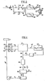
- a spinning device through which a number of fibers are spun into a yarn 2. Without overrunning a speed-sharing device, such as a godet, the yarn is wound up into a winding 6, which is driven in rotation by a motor 9.
- Two detectors 53 and 54 for measuring static electricity are arranged at a distance L from one another near the path of the yarn 2.
- the two detectors consist of electrodes 55 and 56 and correspondingly of signal amplifiers 57 and 58. The detectors do not touch the yarn.
- An electrostatic charge present on the yarn induces alternating voltages in the electrodes 55 and 56, which are amplified by the amplifiers 57 and 58. These amplified voltages x (t) and y (t) are led to a correlation device 61 via the connections 59 and 60. From this, the correlation device 61 derives a signal which is at least approximately the correlation function
- This signal is passed via the connection 62 to the extreme value-searching circuit 63, which serves to find the value ⁇ for which the function ⁇ xy ( T ) has a maximum.
- the circuit 63 adjusts the setting of the delay time in the correlator 61 via a correction device 64 and the lines 65 and 66.
- the signal representing the delay time ⁇ is also passed via a connection 67 to the computer 68.
- the latter outputs a signal to terminal 69, which is the quotient corresponds, where L is the distance between the sensors 53 and 54, T is the set delay time and V is the yarn speed to be calculated.
- the signal from the computer 68 is passed to an automatically operating control unit 70 which serves to regulate the speed of the motor 9 so that the winding speed Vg of the yarn is kept at a desired value V.
- This value is set on the control unit, as indicated schematically by line 71.
- the connection of the controller 70 to the take-up motor 9 is indicated by the reference number 72 and the drive shaft for the yarn package by the dashed line 8.
- FIG. 5 Another embodiment of the control system is shown in FIG. 5.
- the correlator 61 of this device a fixed value for the delay time T is entered, which corresponds to the desired yarn speed V and the equation fulfilled, as indicated by arrow 73.
- the extreme value searching device 63 is connected to an automatic control device 70 via a connection 74.
- the control device 70 serves to set the drive motor 9 to such a speed that the correlation function ⁇ xy ( ⁇ ) reaches its maximum.
- the embodiment according to FIG. 5 in its entirety presents itself as an extreme value-seeking device which is aimed at maximizing the correlation function ⁇ xy ( ⁇ ) by varying the speed of the motor 9.
- the signals from the detectors 53 and 54 for detecting electrostatic charges are passed back to the correlator 61.
- the signal y (t) of the detector 54 is first differentiated to y '(t) by the RC element 75-76. graces.
- Correlator 61 has two polarity detectors in the form of comparators 77 and 78 ,; to which the signals x (t) and y '(t) are fed'.
- the comparators are set to a reference voltage "0" at which they provide a square wave voltage which is positive ("1") when the input signal is positive and which is zero ("0") when the input signal is negative. In this way, the output signals of the comparators indicate the polarity of the corresponding input signals. They are to be designated with sign x (t) and sign y '(t).
- the comparator output does not necessarily have to vary between a positive value and "0", as is the case when the TTL logic system used is used. It is also possible to design the circuit so that this signal varies between a positive and a negative value. For example, the output signal of the comparator can be positive if the input signal is positive and negative if the input signal is negative. It is also conceivable to set a reference voltage on the comparators which has a value deviating from "0". Here it is assumed that, apart from the delay time, which is caused by the distance between the two detectors 53 and 54, the input signals of the two comparators show great similarity both in form and in amplitude.
- the output signals of the comparators 77 and 78 are fed via lines 79 and 80 to a shift register 81 and a multiplier 82.
- the shift register 81 serves to delay the passage of the signal denoted by sign x (t) to the multiplier 82 for a time ⁇ .
- the elements of the shift register are connected to a pulse generator 84 by a schematically indicated line 83.
- the latter is of the type that converts a voltage into a pulse train whose pulse repetition frequency is proportional to the level of the input voltage.
- the output signal of the comparator 77 becomes after a delay time appear at the outlet of the shift register 81.
- This outlet signal sign is sent to multiplier 82 over line 85.
- the multiplier 82 is a logic circuit which supplies an output signal Z to be passed on via line 86. This output signal depends on the input signals, x, y according to the following table:
- the multiplier 82 only outputs an output signal "1" if the polarity of the two input signals via the connections 85 and 80 is the same.
- the logic circuit should therefore have the function: where X and Y represent the signals at the inputs of the multiplier. It will now be clear that the closer the time delay of the shift register at value lies, the output of the multiplier 82 will have the value "1" the longer. So the value the value as close as possible, the shift pulse generator should deliver 84 pulses, the frequency of which is the value corresponds.
- the input of the shift pulse generator 84 is connected to the output of the multiplier 82 via lines 88 and 87, integrator 89 and line 86.
- the multiplier 82 will deliver an output signal "0". This is determined by the integrator 89 as a deviation, which appears integrated at the output 87.
- the frequency of the shift pulse generator 84 is changed in such a sense that the value of the value of comes closer.
- a state arises a, in which the integrator 89 with a voltage U to the shift pulse generator delivers. Since the voltage U is proportional to f . U is also a measure of the yarn speed Vg. From U cf s it follows that is.
- the output voltage U is passed on to the controller 70 via the connections 87 and 69.
- the setpoint for the desired yarn speed was set on this controller.
- This setting option is indicated schematically in FIG. 6 by arrow 71.
- the controller 70 - of the PI type - is connected via the connection 72 to an inverter 90 for supplying the drive motor 9.
- the three-phase motor 9 is a three-phase synchronous motor. It is fed by the inverter 90 via a cable 91.
- the inverter 90 outputs a three-phase current, the frequency of which depends on the level of the DC voltage output by the control device 70.
- the speed of the drive motor 9 is consequently to be controlled with the input voltage coming via the connection 72.
- the inverter is of a type known per se and consists of a converter which converts direct voltage into a three-phase signal of a certain frequency and a power amplifier.
- the yarn speed 'Vg expressed by the voltage U output by the integrator 89
- the input voltage of the inverter 90 and thus the frequency of the three-phase current and the speed of the drive motor 9 remain constant.
- the PI controller 70 changes the input voltage of the inverter so that the yarn speed V is returned to the desired value V. In this way the yarn speed in the spinning zone can be kept at a desired value V without the yarn having to pass through a godet before it reaches the yarn package, which would give it the speed V.
- the grooved roller 5 can function as a so-called lead roller. This means that the peripheral speed of the grooving roller 5 is greater than the yarn speed, whereby the yarn tension after the yarn has passed the grooving roller is lower than before.
- Such a reduction in tension can of course only be achieved if the grooved roll is free - i.e. without touching the thread spool - can turn. In other words, tension cannot be reduced with a roller that is in contact with the yarn package.
- step-up roller e.g. with a trailing roller, the peripheral speed of which is less than the speed of the yarn being fed.
- a wrap angle of 240 ° or greater is recommended.
- FIG. 7 Another modified exemplary embodiment, which is based on the principle of the speed control device according to FIG. 5, is shown in FIG. 7.
- This embodiment differs from that according to FIG. 6 in that the shift pulse generator 84 feeds the shift register 71 with shift pulses of a fixed frequency. This frequency obeys the equation: where n is again the number of elements of the shift register 81, L the distance between the detectors 53 and 54 for measuring the static electricity and V the desired yarn speed. The time it takes for the yarn to travel the distance between the two detectors 53 and 54 is
- the multiplier recognizes, as in the embodiment according to FIG. 6, that the signals' and sign y '(t) do not match. 6, the resulting “false signal” is now passed from multiplier 82 directly to connection to PI controller 70 via connection 86. Controller 70 changes the fre frequency of the three-phase current supplied by the inverter 90 until the false signal from the multiplier 82 is eliminated. The moment the times are the same, and there the yarn speed V 9 is again at its desired value V.
- the desired value is the time available to the yarn to pass the distance L between the two sensors 53 and 54. This desired value is fixed by setting the frequency of the shift pulse generator 84.
- a logic circuit can be used, which instead of the function their inverse function known as the "EXCLUSIVE OR" function:
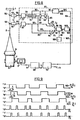
- FIG. 8 Another variant of the speed control system is shown in FIG. 8. This system differs from the ones described above in that the signal y (t) of the detector 54 is not differentiated.
- the input of the penultimate element 92 of the n-bits shift register 81 is connected to a first multiplier 94 via the connection 83.
- the other input of the multiplier 94 is connected to the output of the comparator 78 by means of the connections 95 and 80.
- the last slide register element 96 and the comparator 78 are connected to a multiplier 82.
- the outputs of the multipliers 82 and 94 are connected via connections 86 and 97 to an electronic counter 98, to which 99 pulses with a very constant frequency are supplied by a clock pulse generator 100 via a line.
- the counter 98 outputs its signal via a line 101 to a digital-to-analog converter 102, which in turn outputs its analog output signal to an amplifier 105 via connections 103 and 104.
- the amplifier 105 supplies the amplified analog signal via a connection 106 to the shift pulse generator 84. This pulse generator sends shift pulses via line 83 to the shift register 81.
- the digital-to-analog converter 102 is connected to the controller 70 via a connection 107.
- the correlator 61 is set to a yarn speed V 9 .
- the digital-to-analog converter 102 delivers a signal corresponding to the yarn speed v 9 to the automatic control device 70. If the value of this signal is the desired one set at the connection 71. If the value V is the same, the speed of the drive motor 9 is kept at the preselected value.
- the time required for the yarn to travel through the distance L between the sensors 53 and 54 is then, as follows: The delay caused by the first n-1 elements of the shift register is therefore the same The time delay of the first n-2 elements of the shift register is and for all n elements
- the signal at terminal 93 is thus sign the signal at connection 85 is sign
- the signal sign is between the elements 92 and 96
- the signal at terminal 93 is just as much before the signal sign how the signal at terminal 85 lies behind it (see FIG. 9).
- Multipliers 94 and 82 both formed by an "EXCLUSIVE-OR" gate, provide signals Z 1 and Z 2 , as indicated in FIG. 9.
- the counter 98 works in such a way that the pulses Z 2 on the terminal 86 increase the counter reading, the pulses Z, on the other hand decrease the counter reading on the terminal 97. In the state shown in FIG. 9, in which each pulse Z is followed by a pulse Z 2 of the same duration, the count of the counter remains unchanged in terms of content.
- the number of clock pulses coming from the clock pulse generator 100 which increases the count during the duration of a pulse Z, is always the same as the number of clock pulses with which the count is reduced again during a subsequent pulse Z 2 .
- the digital-to-analog converter 102 converts the counter reading of the counter 98 into a proportional analog signal which, after amplification in the amplifier 105, sets the frequency f s of the shift pulse generator 84 to a value corresponding to the counter reading.
- the peripheral speed of the package and thus the yarn speed gradually increases.
- the time difference between the signals arriving at multiplier 94 and y (t) now decreases as the shift times between the input signals and y (t) increase at multiplier 82.
- the width of the pulses Z 1 becomes smaller, while that of the pulses Z 2 becomes larger.
- the counter 98 is then supplied with more clock pulses per unit of time which increase the counter reading than those which reduce it. The content of the counter is therefore higher, so that the speed signal at connection 107 also increases.
- the controller 70 responds to this deviation by reducing the frequency of the inverter 90, thereby bringing the yarn speed back to its desired value.
- the arrangement according to FIG. 8 has the advantage that no analog differentiator is used there; and a high degree of measurement and control accuracy can be achieved by means of the clock pulse generator 100 with a precisely determined frequency.
- a third multiplier the inputs of which are connected to the outlet of the (n-1) th element of the shift register and the line 80, makes it possible to signal optically and / or acoustically if the equality is reached.
- the output signal of the third multiplier will practically always have the height "0" or "1", depending on whether the logic function X. Y + XY or XY + XY is displayed.
- the invention can also refer to a device for winding a plurality of yarn packages.
- a common correlator can be used for a large number of winding stations, which is connected in succession to the yarn speed sensors of all winding stations.
Landscapes
- Engineering & Computer Science (AREA)
- Textile Engineering (AREA)
- Structural Engineering (AREA)
- Winding Filamentary Materials (AREA)
- Spinning Or Twisting Of Yarns (AREA)
- Filamentary Materials, Packages, And Safety Devices Therefor (AREA)
Applications Claiming Priority (2)
| Application Number | Priority Date | Filing Date | Title |
|---|---|---|---|
| NL7708149 | 1977-07-22 | ||
| NL7708149A NL7708149A (nl) | 1977-07-22 | 1977-07-22 | Inrichting voor het opwikkelen van een garen. |
Publications (2)
| Publication Number | Publication Date |
|---|---|
| EP0000569A1 EP0000569A1 (de) | 1979-02-07 |
| EP0000569B1 true EP0000569B1 (de) | 1980-07-23 |
Family
ID=19828919
Family Applications (2)
| Application Number | Title | Priority Date | Filing Date |
|---|---|---|---|
| EP78100477A Expired EP0000569B1 (de) | 1977-07-22 | 1978-07-21 | Vorrichtung zum Aufspulen von Garnen |
| EP78100478A Expired EP0000721B1 (de) | 1977-07-22 | 1978-07-21 | Vorrichtung zum Aufwickeln von Garn |
Family Applications After (1)
| Application Number | Title | Priority Date | Filing Date |
|---|---|---|---|
| EP78100478A Expired EP0000721B1 (de) | 1977-07-22 | 1978-07-21 | Vorrichtung zum Aufwickeln von Garn |
Country Status (6)
| Country | Link |
|---|---|
| US (1) | US4169565A (online.php) |
| EP (2) | EP0000569B1 (online.php) |
| JP (1) | JPS5438942A (online.php) |
| DE (2) | DE2860064D1 (online.php) |
| IT (1) | IT1106129B (online.php) |
| NL (1) | NL7708149A (online.php) |
Families Citing this family (15)
| Publication number | Priority date | Publication date | Assignee | Title |
|---|---|---|---|---|
| US4244533A (en) * | 1979-09-05 | 1981-01-13 | Ppg Industries, Inc. | Method of operating an air sensor |
| JPS5892255U (ja) * | 1981-12-14 | 1983-06-22 | 帝人株式会社 | 巻取機における安全装置 |
| US4551969A (en) * | 1983-08-02 | 1985-11-12 | Howa Kogyo Kabushiki Kaisha | Apparatus for controlling the winding speed of roving in roving frame |
| US4650133A (en) * | 1984-07-02 | 1987-03-17 | White Frances H | Winder apparatus and method |
| US4615495A (en) * | 1985-06-28 | 1986-10-07 | Dixie Yarns, Inc. | Cylindrical package of low modulus, highly elastic yarn |
| US4688734A (en) * | 1985-06-28 | 1987-08-25 | Dixie Yarns, Inc. | Apparatus and method for tensionless winding of low modulus elastic yarns into a cylindrical package for uniform dyeing |
| US5277373A (en) * | 1991-12-18 | 1994-01-11 | Morton Henry H | Apparatus and method for controlling tension in a moving material |
| DE4225842A1 (de) * | 1992-08-05 | 1994-02-10 | Schlafhorst & Co W | Vorrichtung zum Messen der Geschwindigkeit von Textilfäden an einer Wickeleinrichtung |
| DE4434234C2 (de) * | 1994-09-24 | 2003-06-26 | Schlafhorst & Co W | Vorrichtung zum Bestimmen der Geschwindigkeit eines in Richtung seiner Längsausdehnung bewegten Textilgutes, insbesondere eines Textilfadens |
| US6499688B1 (en) | 1996-07-29 | 2002-12-31 | Ccs Holdings, Inc. | Optical fiber ribbon winding apparatus and method |
| US5996925A (en) * | 1997-03-03 | 1999-12-07 | Toray Engineering Co., Ltd. | Method and apparatus for detecting yarn tension and method for winding yarn |
| GR1003684B (el) * | 2000-11-09 | 2001-10-03 | Νικολαος Καλαιτζης | Μεθοδος και συσκευη μετρησης μηκους και ταχυτητας παραδοσεως νηματος με χρηση ζευγους οπτικων αισθητηρων και προσαρμοστικου ψηφιακου ετεροσυσχετιστη σηματων. |
| DE10118660A1 (de) † | 2001-04-14 | 2002-10-17 | Schlafhorst & Co W | Garnreinigungseinrichtung an der Spulstelle einer Textilmaschine |
| EP1256540A3 (en) * | 2001-05-11 | 2003-07-16 | Murata Kikai Kabushiki Kaisha | Yarn winding machine and yarn winding method |
| DE102007011499B3 (de) * | 2007-03-07 | 2008-07-03 | Vienco Gmbh | Verfahren und Anordnung zur Überwachung und Optimierung eines Spulprozesses |
Family Cites Families (6)
| Publication number | Priority date | Publication date | Assignee | Title |
|---|---|---|---|---|
| DE1535086A1 (de) * | 1965-03-05 | 1970-04-09 | Alucolor Fmn Schuster & Co | Verfahren zur Geschwindigkeits- und Laengenbestimmung von Textilfaeden |
| JPS4824983B1 (online.php) * | 1968-01-27 | 1973-07-25 | ||
| CH554285A (it) * | 1971-04-15 | 1974-09-30 | Savio Spa | Procedimento par azionare i rocchetti e regolare la velocita periferica dei rocchetti nelle macchine roccatrici e/o binatrici di filati e dispositivo per l'esecuzione del procedimento. |
| DE2219755C3 (de) * | 1972-04-21 | 1978-04-06 | Siemens Ag, 1000 Berlin Und 8000 Muenchen | Vorrichtung zum Konstanthalten des Fadenzuges an Präzisionskreuzspulmaschinen |
| FR2182381A5 (online.php) * | 1972-04-28 | 1973-12-07 | Saint Gobain Pont A Mousson | |
| US3931938A (en) * | 1974-03-18 | 1976-01-13 | Toray Industries, Inc. | Method and apparatus for winding yarn into yarn package |
-
1977
- 1977-07-22 NL NL7708149A patent/NL7708149A/xx not_active Application Discontinuation
-
1978
- 1978-07-17 IT IT50331/78A patent/IT1106129B/it active
- 1978-07-17 US US05/925,573 patent/US4169565A/en not_active Expired - Lifetime
- 1978-07-21 EP EP78100477A patent/EP0000569B1/de not_active Expired
- 1978-07-21 DE DE7878100477T patent/DE2860064D1/de not_active Expired
- 1978-07-21 JP JP8929578A patent/JPS5438942A/ja active Granted
- 1978-07-21 DE DE7878100478T patent/DE2861864D1/de not_active Expired
- 1978-07-21 EP EP78100478A patent/EP0000721B1/de not_active Expired
Also Published As
| Publication number | Publication date |
|---|---|
| JPS5438942A (en) | 1979-03-24 |
| EP0000721B1 (de) | 1982-05-26 |
| EP0000721A1 (de) | 1979-02-21 |
| US4169565A (en) | 1979-10-02 |
| DE2860064D1 (en) | 1980-11-13 |
| EP0000569A1 (de) | 1979-02-07 |
| IT1106129B (it) | 1985-11-11 |
| NL7708149A (nl) | 1979-01-24 |
| DE2861864D1 (en) | 1982-07-15 |
| JPS6115020B2 (online.php) | 1986-04-22 |
| IT7850331A0 (it) | 1978-07-17 |
Similar Documents
| Publication | Publication Date | Title |
|---|---|---|
| EP0000721B1 (de) | Vorrichtung zum Aufwickeln von Garn | |
| DE3247545C2 (online.php) | ||
| DE3235837C2 (online.php) | ||
| DE2954584C2 (online.php) | ||
| DE9216261U1 (de) | Vorrichtung zum Aufwickeln einer Bahn | |
| DE10021963A1 (de) | Verfahren und Vorrichtung zum Aufwickeln eines kontinuierlich zulaufenden Fadens | |
| DE2359917B2 (de) | Verfahren zum Erzeugen eines gleichmäßig, kontinuierlichen Faserverbandes und Einrichtung zur Durchführung des Verfahrens | |
| DE2435677A1 (de) | Verfahren und vorrichtung zum messen einer gefoerderten fasermenge waehrend des foerdervorganges | |
| DE2813887C2 (de) | Verfahren und Vorrichtung zum Konstanthalten der Spannung eines Vorgarns zwischen dem Streckwerk und dem Oberteil einer voreilend angetriebenen Spule mit Flügelspindel einer Vorspinnmaschine | |
| DE2052117A1 (de) | Verfahren und Vorrichtung zur Überwachung der Wickelbildung an der Fadenführungstrommel von Spulmaschinen | |
| DE2234610C3 (de) | Vorrichtung zum Konstanthalten der Fadenspannung beim Zuführen eines Fadens zu einer Verarbeitungs-Textilmaschine | |
| DE1804283A1 (de) | Aufwickelvorrichtung fuer bahnfoermiges Gut | |
| DE10296719B4 (de) | Verfahren zum Steuern einer Wickeleinrichtung | |
| DE10236778A1 (de) | Verfahren und Vorrichtung zum Verstrecken von mindestens eines Faserband | |
| DE2914924A1 (de) | Aufspuleinrichtung | |
| DE2230628C3 (de) | Vorrichtung zum Steuern des Antriebs der Verlegevorrichtung von Spulmaschinen, insbesondere bei Drahtziehmaschinen | |
| DE3210244A1 (de) | Verfahren zur spiegelstoerung beim aufwickeln eines fadens in wilder wicklung | |
| EP0617149B1 (de) | Verfahren zur Vergleichmässigung von textilen Faserbändern | |
| DE3723593C1 (en) | Method for regulating a winding motor acting on a winding spindle on a cross-winding machine and cross-winding machine | |
| DE2412153C3 (de) | Vorrichtung zum Konstanthalten der Fadenspannung an Aufspulvorrichtungen | |
| DE4312534A1 (de) | Vorrichtung zur Regelung der Bahnspannungsregelung einer Materialbahn, insbesondere einer Papierbahn | |
| DE1124407B (de) | Spulmaschine zur Erzeugung von Spulen mit ueber der Spulreise vorbestimmter Fadenspannung | |
| DE2802466A1 (de) | Verfahren zum messen der laenge von materialbahnen, insbesondere zum messen der abstaende der transport-randlochung an einer endlospapierbahn sowie vorrichtung zur ausfuehrung dieses verfahrens | |
| DE3433724A1 (de) | Verfahren zum wickeln von eng, vorzugsweise abstandslos gewickelten wicklungslagen von lagenwicklungen und vorrichtung hierfuer | |
| DE1950756A1 (de) | Kontrolleinrichtung fuer laufendes Garn |
Legal Events
| Date | Code | Title | Description |
|---|---|---|---|
| PUAI | Public reference made under article 153(3) epc to a published international application that has entered the european phase |
Free format text: ORIGINAL CODE: 0009012 |
|
| AK | Designated contracting states |
Designated state(s): CH DE GB NL |
|
| 17P | Request for examination filed | ||
| GRAA | (expected) grant |
Free format text: ORIGINAL CODE: 0009210 |
|
| AK | Designated contracting states |
Designated state(s): CH DE GB NL |
|
| REF | Corresponds to: |
Ref document number: 2860064 Country of ref document: DE Date of ref document: 19801113 |
|
| PGFP | Annual fee paid to national office [announced via postgrant information from national office to epo] |
Ref country code: NL Payment date: 19810731 Year of fee payment: 4 |
|
| PG25 | Lapsed in a contracting state [announced via postgrant information from national office to epo] |
Ref country code: NL Effective date: 19830201 |
|
| NLV4 | Nl: lapsed or anulled due to non-payment of the annual fee | ||
| PGFP | Annual fee paid to national office [announced via postgrant information from national office to epo] |
Ref country code: CH Payment date: 19840702 Year of fee payment: 7 |
|
| PGFP | Annual fee paid to national office [announced via postgrant information from national office to epo] |
Ref country code: DE Payment date: 19840705 Year of fee payment: 7 |
|
| PG25 | Lapsed in a contracting state [announced via postgrant information from national office to epo] |
Ref country code: CH Effective date: 19860731 |
|
| REG | Reference to a national code |
Ref country code: CH Ref legal event code: PL |
|
| PG25 | Lapsed in a contracting state [announced via postgrant information from national office to epo] |
Ref country code: DE Effective date: 19870401 |
|
| GBPC | Gb: european patent ceased through non-payment of renewal fee | ||
| PG25 | Lapsed in a contracting state [announced via postgrant information from national office to epo] |
Ref country code: GB Effective date: 19881117 |
|
| PLBE | No opposition filed within time limit |
Free format text: ORIGINAL CODE: 0009261 |
|
| STAA | Information on the status of an ep patent application or granted ep patent |
Free format text: STATUS: NO OPPOSITION FILED WITHIN TIME LIMIT |