CN106943164B - Direct drive endoscope system and method - Google Patents
Direct drive endoscope system and method Download PDFInfo
- Publication number
- CN106943164B CN106943164B CN201610832641.2A CN201610832641A CN106943164B CN 106943164 B CN106943164 B CN 106943164B CN 201610832641 A CN201610832641 A CN 201610832641A CN 106943164 B CN106943164 B CN 106943164B
- Authority
- CN
- China
- Prior art keywords
- guide tube
- tool
- control
- working channel
- track
- Prior art date
- Legal status (The legal status is an assumption and is not a legal conclusion. Google has not performed a legal analysis and makes no representation as to the accuracy of the status listed.)
- Active
Links
- 238000000034 method Methods 0.000 title abstract description 30
- 230000007246 mechanism Effects 0.000 claims description 84
- 238000000926 separation method Methods 0.000 claims description 20
- 230000008859 change Effects 0.000 claims description 14
- 239000004811 fluoropolymer Substances 0.000 claims description 3
- 229920002313 fluoropolymer Polymers 0.000 claims description 3
- 239000012781 shape memory material Substances 0.000 claims description 2
- 230000033001 locomotion Effects 0.000 abstract description 188
- 239000012636 effector Substances 0.000 description 115
- 230000013011 mating Effects 0.000 description 87
- 230000003287 optical effect Effects 0.000 description 76
- 239000012530 fluid Substances 0.000 description 44
- 239000000463 material Substances 0.000 description 38
- 210000001519 tissue Anatomy 0.000 description 19
- 239000007789 gas Substances 0.000 description 13
- 238000003780 insertion Methods 0.000 description 13
- 230000037431 insertion Effects 0.000 description 13
- 238000001356 surgical procedure Methods 0.000 description 13
- 230000001965 increasing effect Effects 0.000 description 12
- 238000005452 bending Methods 0.000 description 9
- 239000007788 liquid Substances 0.000 description 7
- 239000012528 membrane Substances 0.000 description 7
- 230000036961 partial effect Effects 0.000 description 7
- 238000013016 damping Methods 0.000 description 6
- 230000000694 effects Effects 0.000 description 6
- 230000008569 process Effects 0.000 description 6
- 238000001125 extrusion Methods 0.000 description 5
- 239000007787 solid Substances 0.000 description 5
- 238000013519 translation Methods 0.000 description 5
- 239000000853 adhesive Substances 0.000 description 4
- 230000001070 adhesive effect Effects 0.000 description 4
- 230000008901 benefit Effects 0.000 description 4
- 238000000576 coating method Methods 0.000 description 4
- 230000008878 coupling Effects 0.000 description 4
- 238000010168 coupling process Methods 0.000 description 4
- 238000005859 coupling reaction Methods 0.000 description 4
- 230000006870 function Effects 0.000 description 4
- 230000036512 infertility Effects 0.000 description 4
- 238000002271 resection Methods 0.000 description 4
- 230000007704 transition Effects 0.000 description 4
- 210000000707 wrist Anatomy 0.000 description 4
- 238000002679 ablation Methods 0.000 description 3
- 230000004888 barrier function Effects 0.000 description 3
- 239000008280 blood Substances 0.000 description 3
- 210000004369 blood Anatomy 0.000 description 3
- 239000013536 elastomeric material Substances 0.000 description 3
- 210000003811 finger Anatomy 0.000 description 3
- 238000002513 implantation Methods 0.000 description 3
- 208000014674 injury Diseases 0.000 description 3
- 229920001343 polytetrafluoroethylene Polymers 0.000 description 3
- 239000004810 polytetrafluoroethylene Substances 0.000 description 3
- 230000008439 repair process Effects 0.000 description 3
- 239000012858 resilient material Substances 0.000 description 3
- 239000000126 substance Substances 0.000 description 3
- 230000001225 therapeutic effect Effects 0.000 description 3
- 230000008733 trauma Effects 0.000 description 3
- 238000003466 welding Methods 0.000 description 3
- XEEYBQQBJWHFJM-UHFFFAOYSA-N Iron Chemical compound [Fe] XEEYBQQBJWHFJM-UHFFFAOYSA-N 0.000 description 2
- 208000027418 Wounds and injury Diseases 0.000 description 2
- 210000003484 anatomy Anatomy 0.000 description 2
- 238000002399 angioplasty Methods 0.000 description 2
- 239000012620 biological material Substances 0.000 description 2
- 239000011248 coating agent Substances 0.000 description 2
- 230000008602 contraction Effects 0.000 description 2
- 238000005520 cutting process Methods 0.000 description 2
- 230000000994 depressogenic effect Effects 0.000 description 2
- 239000006185 dispersion Substances 0.000 description 2
- 238000000605 extraction Methods 0.000 description 2
- 239000002783 friction material Substances 0.000 description 2
- 210000000232 gallbladder Anatomy 0.000 description 2
- 230000005484 gravity Effects 0.000 description 2
- 239000011810 insulating material Substances 0.000 description 2
- 230000002262 irrigation Effects 0.000 description 2
- 238000003973 irrigation Methods 0.000 description 2
- 230000000670 limiting effect Effects 0.000 description 2
- 210000004072 lung Anatomy 0.000 description 2
- 239000002184 metal Substances 0.000 description 2
- 229910052751 metal Inorganic materials 0.000 description 2
- 230000007935 neutral effect Effects 0.000 description 2
- 229920000642 polymer Polymers 0.000 description 2
- -1 polytetrafluoroethylene Polymers 0.000 description 2
- 230000003014 reinforcing effect Effects 0.000 description 2
- 239000012779 reinforcing material Substances 0.000 description 2
- 210000002784 stomach Anatomy 0.000 description 2
- 238000012800 visualization Methods 0.000 description 2
- 238000004804 winding Methods 0.000 description 2
- KKJUPNGICOCCDW-UHFFFAOYSA-N 7-N,N-Dimethylamino-1,2,3,4,5-pentathiocyclooctane Chemical compound CN(C)C1CSSSSSC1 KKJUPNGICOCCDW-UHFFFAOYSA-N 0.000 description 1
- 206010002329 Aneurysm Diseases 0.000 description 1
- 241000894006 Bacteria Species 0.000 description 1
- 208000023514 Barrett esophagus Diseases 0.000 description 1
- 208000023665 Barrett oesophagus Diseases 0.000 description 1
- 208000024172 Cardiovascular disease Diseases 0.000 description 1
- 208000005189 Embolism Diseases 0.000 description 1
- 201000009273 Endometriosis Diseases 0.000 description 1
- CWYNVVGOOAEACU-UHFFFAOYSA-N Fe2+ Chemical compound [Fe+2] CWYNVVGOOAEACU-UHFFFAOYSA-N 0.000 description 1
- 206010019909 Hernia Diseases 0.000 description 1
- 206010021639 Incontinence Diseases 0.000 description 1
- 208000000913 Kidney Calculi Diseases 0.000 description 1
- 206010058467 Lung neoplasm malignant Diseases 0.000 description 1
- 206010028980 Neoplasm Diseases 0.000 description 1
- 206010029148 Nephrolithiasis Diseases 0.000 description 1
- 239000004677 Nylon Substances 0.000 description 1
- 208000008589 Obesity Diseases 0.000 description 1
- 241000405070 Percophidae Species 0.000 description 1
- 208000007097 Urinary Bladder Neoplasms Diseases 0.000 description 1
- 210000001015 abdomen Anatomy 0.000 description 1
- 210000003815 abdominal wall Anatomy 0.000 description 1
- 239000002253 acid Substances 0.000 description 1
- 230000003213 activating effect Effects 0.000 description 1
- 210000000436 anus Anatomy 0.000 description 1
- 230000001746 atrial effect Effects 0.000 description 1
- 230000004323 axial length Effects 0.000 description 1
- 239000013060 biological fluid Substances 0.000 description 1
- 230000005540 biological transmission Effects 0.000 description 1
- 230000000740 bleeding effect Effects 0.000 description 1
- 210000004204 blood vessel Anatomy 0.000 description 1
- 210000001124 body fluid Anatomy 0.000 description 1
- 238000012512 characterization method Methods 0.000 description 1
- 210000001072 colon Anatomy 0.000 description 1
- 238000004891 communication Methods 0.000 description 1
- 239000002131 composite material Substances 0.000 description 1
- 238000010276 construction Methods 0.000 description 1
- 238000007887 coronary angioplasty Methods 0.000 description 1
- 238000002316 cosmetic surgery Methods 0.000 description 1
- 230000001419 dependent effect Effects 0.000 description 1
- 230000000881 depressing effect Effects 0.000 description 1
- 238000011161 development Methods 0.000 description 1
- 230000018109 developmental process Effects 0.000 description 1
- 238000003745 diagnosis Methods 0.000 description 1
- 238000007599 discharging Methods 0.000 description 1
- 238000011038 discontinuous diafiltration by volume reduction Methods 0.000 description 1
- 239000013013 elastic material Substances 0.000 description 1
- 239000012777 electrically insulating material Substances 0.000 description 1
- 239000011263 electroactive material Substances 0.000 description 1
- 238000002001 electrophysiology Methods 0.000 description 1
- 230000007831 electrophysiology Effects 0.000 description 1
- 238000013171 endarterectomy Methods 0.000 description 1
- 230000002708 enhancing effect Effects 0.000 description 1
- 230000007159 enucleation Effects 0.000 description 1
- 239000000835 fiber Substances 0.000 description 1
- 210000005224 forefinger Anatomy 0.000 description 1
- 230000008014 freezing Effects 0.000 description 1
- 238000007710 freezing Methods 0.000 description 1
- 208000021302 gastroesophageal reflux disease Diseases 0.000 description 1
- 210000004907 gland Anatomy 0.000 description 1
- 210000004247 hand Anatomy 0.000 description 1
- 208000025339 heart septal defect Diseases 0.000 description 1
- 239000002654 heat shrinkable material Substances 0.000 description 1
- 208000003906 hydrocephalus Diseases 0.000 description 1
- 238000009802 hysterectomy Methods 0.000 description 1
- 230000006698 induction Effects 0.000 description 1
- 230000002401 inhibitory effect Effects 0.000 description 1
- 230000000977 initiatory effect Effects 0.000 description 1
- 238000007689 inspection Methods 0.000 description 1
- 230000003993 interaction Effects 0.000 description 1
- 210000000936 intestine Anatomy 0.000 description 1
- 229910052742 iron Inorganic materials 0.000 description 1
- 230000001788 irregular Effects 0.000 description 1
- 238000002357 laparoscopic surgery Methods 0.000 description 1
- 210000000867 larynx Anatomy 0.000 description 1
- 210000005248 left atrial appendage Anatomy 0.000 description 1
- 230000003902 lesion Effects 0.000 description 1
- 210000004185 liver Anatomy 0.000 description 1
- 230000001050 lubricating effect Effects 0.000 description 1
- 201000005202 lung cancer Diseases 0.000 description 1
- 208000020816 lung neoplasm Diseases 0.000 description 1
- 239000011553 magnetic fluid Substances 0.000 description 1
- 210000001349 mammary artery Anatomy 0.000 description 1
- 238000013507 mapping Methods 0.000 description 1
- 239000003550 marker Substances 0.000 description 1
- 238000005259 measurement Methods 0.000 description 1
- 150000002739 metals Chemical class 0.000 description 1
- 238000003032 molecular docking Methods 0.000 description 1
- 229920001778 nylon Polymers 0.000 description 1
- 235000020824 obesity Nutrition 0.000 description 1
- 230000000399 orthopedic effect Effects 0.000 description 1
- 210000002741 palatine tonsil Anatomy 0.000 description 1
- 230000037361 pathway Effects 0.000 description 1
- 230000021715 photosynthesis, light harvesting Effects 0.000 description 1
- 239000004033 plastic Substances 0.000 description 1
- 229920003023 plastic Polymers 0.000 description 1
- 229920002635 polyurethane Polymers 0.000 description 1
- 239000004814 polyurethane Substances 0.000 description 1
- 230000035935 pregnancy Effects 0.000 description 1
- 238000003825 pressing Methods 0.000 description 1
- 210000002307 prostate Anatomy 0.000 description 1
- 230000002829 reductive effect Effects 0.000 description 1
- 230000004044 response Effects 0.000 description 1
- 208000037803 restenosis Diseases 0.000 description 1
- 230000000250 revascularization Effects 0.000 description 1
- 238000005096 rolling process Methods 0.000 description 1
- 239000000523 sample Substances 0.000 description 1
- 238000005070 sampling Methods 0.000 description 1
- 238000007789 sealing Methods 0.000 description 1
- 229910001285 shape-memory alloy Inorganic materials 0.000 description 1
- 229910052710 silicon Inorganic materials 0.000 description 1
- 239000010703 silicon Substances 0.000 description 1
- 201000002859 sleep apnea Diseases 0.000 description 1
- 239000007921 spray Substances 0.000 description 1
- 238000005728 strengthening Methods 0.000 description 1
- 230000001629 suppression Effects 0.000 description 1
- 210000003813 thumb Anatomy 0.000 description 1
- 230000017423 tissue regeneration Effects 0.000 description 1
- 238000012546 transfer Methods 0.000 description 1
- 239000012780 transparent material Substances 0.000 description 1
- 210000000626 ureter Anatomy 0.000 description 1
- 210000003708 urethra Anatomy 0.000 description 1
- 210000001215 vagina Anatomy 0.000 description 1
- 210000003462 vein Anatomy 0.000 description 1
- 230000002861 ventricular Effects 0.000 description 1
- 125000000391 vinyl group Chemical group [H]C([*])=C([H])[H] 0.000 description 1
- 229920002554 vinyl polymer Polymers 0.000 description 1
- 230000000007 visual effect Effects 0.000 description 1
- XLYOFNOQVPJJNP-UHFFFAOYSA-N water Substances O XLYOFNOQVPJJNP-UHFFFAOYSA-N 0.000 description 1
Images


Classifications
-
- A—HUMAN NECESSITIES
- A61—MEDICAL OR VETERINARY SCIENCE; HYGIENE
- A61B—DIAGNOSIS; SURGERY; IDENTIFICATION
- A61B1/00—Instruments for performing medical examinations of the interior of cavities or tubes of the body by visual or photographical inspection, e.g. endoscopes; Illuminating arrangements therefor
- A61B1/00002—Operational features of endoscopes
- A61B1/00039—Operational features of endoscopes provided with input arrangements for the user
- A61B1/00042—Operational features of endoscopes provided with input arrangements for the user for mechanical operation
-
- A—HUMAN NECESSITIES
- A61—MEDICAL OR VETERINARY SCIENCE; HYGIENE
- A61B—DIAGNOSIS; SURGERY; IDENTIFICATION
- A61B17/00—Surgical instruments, devices or methods, e.g. tourniquets
- A61B17/00234—Surgical instruments, devices or methods, e.g. tourniquets for minimally invasive surgery
-
- A—HUMAN NECESSITIES
- A61—MEDICAL OR VETERINARY SCIENCE; HYGIENE
- A61B—DIAGNOSIS; SURGERY; IDENTIFICATION
- A61B1/00—Instruments for performing medical examinations of the interior of cavities or tubes of the body by visual or photographical inspection, e.g. endoscopes; Illuminating arrangements therefor
- A61B1/00064—Constructional details of the endoscope body
- A61B1/00071—Insertion part of the endoscope body
- A61B1/0008—Insertion part of the endoscope body characterised by distal tip features
- A61B1/00087—Tools
-
- A—HUMAN NECESSITIES
- A61—MEDICAL OR VETERINARY SCIENCE; HYGIENE
- A61B—DIAGNOSIS; SURGERY; IDENTIFICATION
- A61B1/00—Instruments for performing medical examinations of the interior of cavities or tubes of the body by visual or photographical inspection, e.g. endoscopes; Illuminating arrangements therefor
- A61B1/00131—Accessories for endoscopes
- A61B1/0014—Fastening element for attaching accessories to the outside of an endoscope, e.g. clips, clamps or bands
-
- A—HUMAN NECESSITIES
- A61—MEDICAL OR VETERINARY SCIENCE; HYGIENE
- A61B—DIAGNOSIS; SURGERY; IDENTIFICATION
- A61B1/00—Instruments for performing medical examinations of the interior of cavities or tubes of the body by visual or photographical inspection, e.g. endoscopes; Illuminating arrangements therefor
- A61B1/00147—Holding or positioning arrangements
- A61B1/00154—Holding or positioning arrangements using guiding arrangements for insertion
-
- A—HUMAN NECESSITIES
- A61—MEDICAL OR VETERINARY SCIENCE; HYGIENE
- A61B—DIAGNOSIS; SURGERY; IDENTIFICATION
- A61B1/00—Instruments for performing medical examinations of the interior of cavities or tubes of the body by visual or photographical inspection, e.g. endoscopes; Illuminating arrangements therefor
- A61B1/00163—Optical arrangements
- A61B1/00165—Optical arrangements with light-conductive means, e.g. fibre optics
-
- A—HUMAN NECESSITIES
- A61—MEDICAL OR VETERINARY SCIENCE; HYGIENE
- A61B—DIAGNOSIS; SURGERY; IDENTIFICATION
- A61B1/00—Instruments for performing medical examinations of the interior of cavities or tubes of the body by visual or photographical inspection, e.g. endoscopes; Illuminating arrangements therefor
- A61B1/005—Flexible endoscopes
- A61B1/0051—Flexible endoscopes with controlled bending of insertion part
- A61B1/0052—Constructional details of control elements, e.g. handles
-
- A—HUMAN NECESSITIES
- A61—MEDICAL OR VETERINARY SCIENCE; HYGIENE
- A61B—DIAGNOSIS; SURGERY; IDENTIFICATION
- A61B1/00—Instruments for performing medical examinations of the interior of cavities or tubes of the body by visual or photographical inspection, e.g. endoscopes; Illuminating arrangements therefor
- A61B1/012—Instruments for performing medical examinations of the interior of cavities or tubes of the body by visual or photographical inspection, e.g. endoscopes; Illuminating arrangements therefor characterised by internal passages or accessories therefor
- A61B1/018—Instruments for performing medical examinations of the interior of cavities or tubes of the body by visual or photographical inspection, e.g. endoscopes; Illuminating arrangements therefor characterised by internal passages or accessories therefor for receiving instruments
-
- A—HUMAN NECESSITIES
- A61—MEDICAL OR VETERINARY SCIENCE; HYGIENE
- A61B—DIAGNOSIS; SURGERY; IDENTIFICATION
- A61B17/00—Surgical instruments, devices or methods, e.g. tourniquets
- A61B17/28—Surgical forceps
- A61B17/29—Forceps for use in minimally invasive surgery
-
- A—HUMAN NECESSITIES
- A61—MEDICAL OR VETERINARY SCIENCE; HYGIENE
- A61B—DIAGNOSIS; SURGERY; IDENTIFICATION
- A61B34/00—Computer-aided surgery; Manipulators or robots specially adapted for use in surgery
- A61B34/70—Manipulators specially adapted for use in surgery
-
- A—HUMAN NECESSITIES
- A61—MEDICAL OR VETERINARY SCIENCE; HYGIENE
- A61B—DIAGNOSIS; SURGERY; IDENTIFICATION
- A61B34/00—Computer-aided surgery; Manipulators or robots specially adapted for use in surgery
- A61B34/70—Manipulators specially adapted for use in surgery
- A61B34/71—Manipulators operated by drive cable mechanisms
-
- A—HUMAN NECESSITIES
- A61—MEDICAL OR VETERINARY SCIENCE; HYGIENE
- A61B—DIAGNOSIS; SURGERY; IDENTIFICATION
- A61B1/00—Instruments for performing medical examinations of the interior of cavities or tubes of the body by visual or photographical inspection, e.g. endoscopes; Illuminating arrangements therefor
- A61B1/00163—Optical arrangements
- A61B1/00174—Optical arrangements characterised by the viewing angles
- A61B1/00183—Optical arrangements characterised by the viewing angles for variable viewing angles
-
- A—HUMAN NECESSITIES
- A61—MEDICAL OR VETERINARY SCIENCE; HYGIENE
- A61B—DIAGNOSIS; SURGERY; IDENTIFICATION
- A61B1/00—Instruments for performing medical examinations of the interior of cavities or tubes of the body by visual or photographical inspection, e.g. endoscopes; Illuminating arrangements therefor
- A61B1/005—Flexible endoscopes
- A61B1/0051—Flexible endoscopes with controlled bending of insertion part
- A61B1/0057—Constructional details of force transmission elements, e.g. control wires
-
- A—HUMAN NECESSITIES
- A61—MEDICAL OR VETERINARY SCIENCE; HYGIENE
- A61B—DIAGNOSIS; SURGERY; IDENTIFICATION
- A61B1/00—Instruments for performing medical examinations of the interior of cavities or tubes of the body by visual or photographical inspection, e.g. endoscopes; Illuminating arrangements therefor
- A61B1/12—Instruments for performing medical examinations of the interior of cavities or tubes of the body by visual or photographical inspection, e.g. endoscopes; Illuminating arrangements therefor with cooling or rinsing arrangements
-
- A—HUMAN NECESSITIES
- A61—MEDICAL OR VETERINARY SCIENCE; HYGIENE
- A61B—DIAGNOSIS; SURGERY; IDENTIFICATION
- A61B1/00—Instruments for performing medical examinations of the interior of cavities or tubes of the body by visual or photographical inspection, e.g. endoscopes; Illuminating arrangements therefor
- A61B1/313—Instruments for performing medical examinations of the interior of cavities or tubes of the body by visual or photographical inspection, e.g. endoscopes; Illuminating arrangements therefor for introducing through surgical openings, e.g. laparoscopes
- A61B1/3132—Instruments for performing medical examinations of the interior of cavities or tubes of the body by visual or photographical inspection, e.g. endoscopes; Illuminating arrangements therefor for introducing through surgical openings, e.g. laparoscopes for laparoscopy
-
- A—HUMAN NECESSITIES
- A61—MEDICAL OR VETERINARY SCIENCE; HYGIENE
- A61B—DIAGNOSIS; SURGERY; IDENTIFICATION
- A61B10/00—Other methods or instruments for diagnosis, e.g. instruments for taking a cell sample, for biopsy, for vaccination diagnosis; Sex determination; Ovulation-period determination; Throat striking implements
- A61B10/02—Instruments for taking cell samples or for biopsy
- A61B10/06—Biopsy forceps, e.g. with cup-shaped jaws
-
- A—HUMAN NECESSITIES
- A61—MEDICAL OR VETERINARY SCIENCE; HYGIENE
- A61B—DIAGNOSIS; SURGERY; IDENTIFICATION
- A61B17/00—Surgical instruments, devices or methods, e.g. tourniquets
- A61B17/02—Surgical instruments, devices or methods, e.g. tourniquets for holding wounds open; Tractors
- A61B17/0218—Surgical instruments, devices or methods, e.g. tourniquets for holding wounds open; Tractors for minimally invasive surgery
-
- A—HUMAN NECESSITIES
- A61—MEDICAL OR VETERINARY SCIENCE; HYGIENE
- A61B—DIAGNOSIS; SURGERY; IDENTIFICATION
- A61B17/00—Surgical instruments, devices or methods, e.g. tourniquets
- A61B17/04—Surgical instruments, devices or methods, e.g. tourniquets for suturing wounds; Holders or packages for needles or suture materials
- A61B17/0469—Suturing instruments for use in minimally invasive surgery, e.g. endoscopic surgery
-
- A—HUMAN NECESSITIES
- A61—MEDICAL OR VETERINARY SCIENCE; HYGIENE
- A61B—DIAGNOSIS; SURGERY; IDENTIFICATION
- A61B17/00—Surgical instruments, devices or methods, e.g. tourniquets
- A61B17/32—Surgical cutting instruments
- A61B17/320016—Endoscopic cutting instruments, e.g. arthroscopes, resectoscopes
-
- A—HUMAN NECESSITIES
- A61—MEDICAL OR VETERINARY SCIENCE; HYGIENE
- A61B—DIAGNOSIS; SURGERY; IDENTIFICATION
- A61B17/00—Surgical instruments, devices or methods, e.g. tourniquets
- A61B2017/00017—Electrical control of surgical instruments
- A61B2017/00212—Electrical control of surgical instruments using remote controls
-
- A—HUMAN NECESSITIES
- A61—MEDICAL OR VETERINARY SCIENCE; HYGIENE
- A61B—DIAGNOSIS; SURGERY; IDENTIFICATION
- A61B17/00—Surgical instruments, devices or methods, e.g. tourniquets
- A61B17/00234—Surgical instruments, devices or methods, e.g. tourniquets for minimally invasive surgery
- A61B2017/00238—Type of minimally invasive operation
-
- A—HUMAN NECESSITIES
- A61—MEDICAL OR VETERINARY SCIENCE; HYGIENE
- A61B—DIAGNOSIS; SURGERY; IDENTIFICATION
- A61B17/00—Surgical instruments, devices or methods, e.g. tourniquets
- A61B17/00234—Surgical instruments, devices or methods, e.g. tourniquets for minimally invasive surgery
- A61B2017/00287—Bags for minimally invasive surgery
-
- A—HUMAN NECESSITIES
- A61—MEDICAL OR VETERINARY SCIENCE; HYGIENE
- A61B—DIAGNOSIS; SURGERY; IDENTIFICATION
- A61B17/00—Surgical instruments, devices or methods, e.g. tourniquets
- A61B17/00234—Surgical instruments, devices or methods, e.g. tourniquets for minimally invasive surgery
- A61B2017/00292—Surgical instruments, devices or methods, e.g. tourniquets for minimally invasive surgery mounted on or guided by flexible, e.g. catheter-like, means
- A61B2017/003—Steerable
- A61B2017/00305—Constructional details of the flexible means
- A61B2017/00314—Separate linked members
-
- A—HUMAN NECESSITIES
- A61—MEDICAL OR VETERINARY SCIENCE; HYGIENE
- A61B—DIAGNOSIS; SURGERY; IDENTIFICATION
- A61B17/00—Surgical instruments, devices or methods, e.g. tourniquets
- A61B17/00234—Surgical instruments, devices or methods, e.g. tourniquets for minimally invasive surgery
- A61B2017/00292—Surgical instruments, devices or methods, e.g. tourniquets for minimally invasive surgery mounted on or guided by flexible, e.g. catheter-like, means
- A61B2017/003—Steerable
- A61B2017/00318—Steering mechanisms
- A61B2017/00323—Cables or rods
-
- A—HUMAN NECESSITIES
- A61—MEDICAL OR VETERINARY SCIENCE; HYGIENE
- A61B—DIAGNOSIS; SURGERY; IDENTIFICATION
- A61B17/00—Surgical instruments, devices or methods, e.g. tourniquets
- A61B17/00234—Surgical instruments, devices or methods, e.g. tourniquets for minimally invasive surgery
- A61B2017/00292—Surgical instruments, devices or methods, e.g. tourniquets for minimally invasive surgery mounted on or guided by flexible, e.g. catheter-like, means
- A61B2017/003—Steerable
- A61B2017/00318—Steering mechanisms
- A61B2017/00331—Steering mechanisms with preformed bends
-
- A—HUMAN NECESSITIES
- A61—MEDICAL OR VETERINARY SCIENCE; HYGIENE
- A61B—DIAGNOSIS; SURGERY; IDENTIFICATION
- A61B17/00—Surgical instruments, devices or methods, e.g. tourniquets
- A61B17/00234—Surgical instruments, devices or methods, e.g. tourniquets for minimally invasive surgery
- A61B2017/00292—Surgical instruments, devices or methods, e.g. tourniquets for minimally invasive surgery mounted on or guided by flexible, e.g. catheter-like, means
- A61B2017/0034—Surgical instruments, devices or methods, e.g. tourniquets for minimally invasive surgery mounted on or guided by flexible, e.g. catheter-like, means adapted to be inserted through a working channel of an endoscope
-
- A—HUMAN NECESSITIES
- A61—MEDICAL OR VETERINARY SCIENCE; HYGIENE
- A61B—DIAGNOSIS; SURGERY; IDENTIFICATION
- A61B17/00—Surgical instruments, devices or methods, e.g. tourniquets
- A61B17/00234—Surgical instruments, devices or methods, e.g. tourniquets for minimally invasive surgery
- A61B2017/00353—Surgical instruments, devices or methods, e.g. tourniquets for minimally invasive surgery one mechanical instrument performing multiple functions, e.g. cutting and grasping
-
- A—HUMAN NECESSITIES
- A61—MEDICAL OR VETERINARY SCIENCE; HYGIENE
- A61B—DIAGNOSIS; SURGERY; IDENTIFICATION
- A61B17/00—Surgical instruments, devices or methods, e.g. tourniquets
- A61B17/00234—Surgical instruments, devices or methods, e.g. tourniquets for minimally invasive surgery
- A61B2017/00362—Packages or dispensers for MIS instruments
-
- A—HUMAN NECESSITIES
- A61—MEDICAL OR VETERINARY SCIENCE; HYGIENE
- A61B—DIAGNOSIS; SURGERY; IDENTIFICATION
- A61B17/00—Surgical instruments, devices or methods, e.g. tourniquets
- A61B2017/00367—Details of actuation of instruments, e.g. relations between pushing buttons, or the like, and activation of the tool, working tip, or the like
- A61B2017/00371—Multiple actuation, e.g. pushing of two buttons, or two working tips becoming operational
-
- A—HUMAN NECESSITIES
- A61—MEDICAL OR VETERINARY SCIENCE; HYGIENE
- A61B—DIAGNOSIS; SURGERY; IDENTIFICATION
- A61B17/00—Surgical instruments, devices or methods, e.g. tourniquets
- A61B2017/00367—Details of actuation of instruments, e.g. relations between pushing buttons, or the like, and activation of the tool, working tip, or the like
- A61B2017/00398—Details of actuation of instruments, e.g. relations between pushing buttons, or the like, and activation of the tool, working tip, or the like using powered actuators, e.g. stepper motors, solenoids
-
- A—HUMAN NECESSITIES
- A61—MEDICAL OR VETERINARY SCIENCE; HYGIENE
- A61B—DIAGNOSIS; SURGERY; IDENTIFICATION
- A61B17/00—Surgical instruments, devices or methods, e.g. tourniquets
- A61B2017/0046—Surgical instruments, devices or methods, e.g. tourniquets with a releasable handle; with handle and operating part separable
- A61B2017/00469—Surgical instruments, devices or methods, e.g. tourniquets with a releasable handle; with handle and operating part separable for insertion of instruments, e.g. guide wire, optical fibre
-
- A—HUMAN NECESSITIES
- A61—MEDICAL OR VETERINARY SCIENCE; HYGIENE
- A61B—DIAGNOSIS; SURGERY; IDENTIFICATION
- A61B17/00—Surgical instruments, devices or methods, e.g. tourniquets
- A61B2017/00831—Material properties
- A61B2017/00876—Material properties magnetic
-
- A—HUMAN NECESSITIES
- A61—MEDICAL OR VETERINARY SCIENCE; HYGIENE
- A61B—DIAGNOSIS; SURGERY; IDENTIFICATION
- A61B17/00—Surgical instruments, devices or methods, e.g. tourniquets
- A61B2017/00973—Surgical instruments, devices or methods, e.g. tourniquets pedal-operated
-
- A—HUMAN NECESSITIES
- A61—MEDICAL OR VETERINARY SCIENCE; HYGIENE
- A61B—DIAGNOSIS; SURGERY; IDENTIFICATION
- A61B17/00—Surgical instruments, devices or methods, e.g. tourniquets
- A61B17/28—Surgical forceps
- A61B17/29—Forceps for use in minimally invasive surgery
- A61B2017/2901—Details of shaft
- A61B2017/2905—Details of shaft flexible
-
- A—HUMAN NECESSITIES
- A61—MEDICAL OR VETERINARY SCIENCE; HYGIENE
- A61B—DIAGNOSIS; SURGERY; IDENTIFICATION
- A61B17/00—Surgical instruments, devices or methods, e.g. tourniquets
- A61B17/28—Surgical forceps
- A61B17/29—Forceps for use in minimally invasive surgery
- A61B2017/2901—Details of shaft
- A61B2017/2906—Multiple forceps
-
- A—HUMAN NECESSITIES
- A61—MEDICAL OR VETERINARY SCIENCE; HYGIENE
- A61B—DIAGNOSIS; SURGERY; IDENTIFICATION
- A61B17/00—Surgical instruments, devices or methods, e.g. tourniquets
- A61B17/28—Surgical forceps
- A61B17/29—Forceps for use in minimally invasive surgery
- A61B2017/2926—Details of heads or jaws
- A61B2017/2931—Details of heads or jaws with releasable head
-
- A—HUMAN NECESSITIES
- A61—MEDICAL OR VETERINARY SCIENCE; HYGIENE
- A61B—DIAGNOSIS; SURGERY; IDENTIFICATION
- A61B17/00—Surgical instruments, devices or methods, e.g. tourniquets
- A61B17/34—Trocars; Puncturing needles
- A61B17/3417—Details of tips or shafts, e.g. grooves, expandable, bendable; Multiple coaxial sliding cannulas, e.g. for dilating
- A61B17/3421—Cannulas
- A61B2017/3445—Cannulas used as instrument channel for multiple instruments
- A61B2017/3447—Linked multiple cannulas
-
- A—HUMAN NECESSITIES
- A61—MEDICAL OR VETERINARY SCIENCE; HYGIENE
- A61B—DIAGNOSIS; SURGERY; IDENTIFICATION
- A61B90/00—Instruments, implements or accessories specially adapted for surgery or diagnosis and not covered by any of the groups A61B1/00 - A61B50/00, e.g. for luxation treatment or for protecting wound edges
- A61B90/08—Accessories or related features not otherwise provided for
- A61B2090/0807—Indication means
- A61B2090/0811—Indication means for the position of a particular part of an instrument with respect to the rest of the instrument, e.g. position of the anvil of a stapling instrument
-
- A—HUMAN NECESSITIES
- A61—MEDICAL OR VETERINARY SCIENCE; HYGIENE
- A61B—DIAGNOSIS; SURGERY; IDENTIFICATION
- A61B90/00—Instruments, implements or accessories specially adapted for surgery or diagnosis and not covered by any of the groups A61B1/00 - A61B50/00, e.g. for luxation treatment or for protecting wound edges
- A61B90/36—Image-producing devices or illumination devices not otherwise provided for
- A61B90/37—Surgical systems with images on a monitor during operation
- A61B2090/374—NMR or MRI
-
- A—HUMAN NECESSITIES
- A61—MEDICAL OR VETERINARY SCIENCE; HYGIENE
- A61B—DIAGNOSIS; SURGERY; IDENTIFICATION
- A61B34/00—Computer-aided surgery; Manipulators or robots specially adapted for use in surgery
- A61B34/10—Computer-aided planning, simulation or modelling of surgical operations
-
- A—HUMAN NECESSITIES
- A61—MEDICAL OR VETERINARY SCIENCE; HYGIENE
- A61B—DIAGNOSIS; SURGERY; IDENTIFICATION
- A61B34/00—Computer-aided surgery; Manipulators or robots specially adapted for use in surgery
- A61B34/70—Manipulators specially adapted for use in surgery
- A61B34/74—Manipulators with manual electric input means
-
- A—HUMAN NECESSITIES
- A61—MEDICAL OR VETERINARY SCIENCE; HYGIENE
- A61B—DIAGNOSIS; SURGERY; IDENTIFICATION
- A61B90/00—Instruments, implements or accessories specially adapted for surgery or diagnosis and not covered by any of the groups A61B1/00 - A61B50/00, e.g. for luxation treatment or for protecting wound edges
- A61B90/10—Instruments, implements or accessories specially adapted for surgery or diagnosis and not covered by any of the groups A61B1/00 - A61B50/00, e.g. for luxation treatment or for protecting wound edges for stereotaxic surgery, e.g. frame-based stereotaxis
- A61B90/11—Instruments, implements or accessories specially adapted for surgery or diagnosis and not covered by any of the groups A61B1/00 - A61B50/00, e.g. for luxation treatment or for protecting wound edges for stereotaxic surgery, e.g. frame-based stereotaxis with guides for needles or instruments, e.g. arcuate slides or ball joints
Abstract
Various systems and methods are disclosed that facilitate controlling one or more tools. The system can allow a user to control multiple degrees of freedom. One such system allows a user to control multiple degrees of freedom of two tools simultaneously. Another such system allows a user to control multiple degrees of freedom with a single hand. Also described herein are frames and rails for supporting and/or constraining the motion of one or more tools.
Description
Cross Reference to Related Applications
Priority is claimed in provisional application 60/872,155 entitled "System and method for Endoluminal surgery" filed on 1/12/2006 and provisional application 60/909,219 entitled "direct drive endoscopic System and method" filed on 30/3/2007, both of which are hereby incorporated by reference.
Background
Minimally invasive surgical tools, such as endoscopic and laparoscopic devices, can provide surgical access to the surgical site and minimize trauma to the patient. While the increasing capabilities of such treatment devices allow physicians to perform a wider variety of procedures via traditional minimally invasive routes, further refinements may allow surgical access via less invasive routes. Mechanical systems have been proposed to allow surgical access through the natural orifice. The user interface is remote from the surgical tool and/or the end effector. Unfortunately, these systems are often expensive and complex. In addition, these systems do not provide the tactile user feedback that conventional devices can provide.
Accordingly, there is a reason for further refinement of conventional minimally invasive surgical devices, and there is a need for the development of new surgical systems.
Disclosure of Invention
Various systems and methods for driving a tool are described herein. In one aspect, the tool may be actuated via user input force transmitted to the distal working area. The tools and/or other elements of the various systems described below are capable of moving in multiple degrees of freedom in response to user input forces. The system described herein can also help control the multiple degrees of freedom. For example, the multiple degrees of freedom may be actuated with only a single hand.
In one embodiment, a system is provided that includes a guide tube. The guide tube may include at least one channel therein for the delivery of surgical instruments. In one aspect, a plurality of surgical instruments may be delivered through one or more channels in the guide tube. The guide tube may provide at least one degree of freedom for the system, and in another embodiment may provide multiple degrees of freedom.
In one aspect, the guide tube may receive a flexible endoscope or other visualization instrument to allow visualization of a surgical site. In another aspect, the guide tube may receive a tool for tissue repair, characterization and/or ablation. The endoscope, guide tube, and/or tool may provide additional degrees of freedom to the system. For example, the tool may provide at least one degree of freedom by manual control, and in other aspects, two or more degrees of freedom.
In another aspect, the guide tube, tool and/or optical device may work with a support frame. The frame may, for example, cooperate with the tool and assist in controlling additional degrees of freedom. In addition, the frame may define an ergonomic working area for the physician, as well as provide a reference relative to the patient.
Further described herein is a method of accessing a surgical site. In one embodiment, the guide tube may be guided to the surgical site through a natural orifice. An optical device and at least one surgical tool may be delivered to a surgical site through a channel in the guide tube. The user may then view and manipulate the tissue mass through the optical device and the at least one surgical tool. In one aspect, a user may interact with one or more controllers mated to the support frame while partially actuating the at least one surgical tool.
Drawings
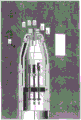
FIG. 1 is a perspective view of one embodiment of a system described herein.
Fig. 2A is a sectional view taken along line a-a of fig. 1.
Fig. 2B is another embodiment of a cross-sectional view taken along line a-a of fig. 1.
Fig. 3A is a disassembled view of a portion of the system of fig. 1.
Fig. 3B is a cross-sectional view of a portion of the system of fig. 1.
Fig. 4A is a cross-sectional view of a portion of the system of fig. 1.
Fig. 4B is a cross-sectional view of a portion of the system of fig. 1.
Fig. 5A is a front view of an exemplary element of the systems described herein.
Fig. 5B is a front view of another embodiment of the element of fig. 5A.
Fig. 6A is a cross-sectional view of an exemplary embodiment of an endcap described herein.
Fig. 6B is another cross-sectional view of the endcap of fig. 6A.
Fig. 7A is a perspective view of one exemplary embodiment of a channel distributor as described herein.
Fig. 7B is a longitudinal cross-sectional view of the channel distributor of fig. 7A.
Fig. 7C is a perspective view of the channel distributor of fig. 7A positioned within a guide tube.
Figure 7D is an elevation view of an exemplary embodiment of a guide tube described herein.
Figure 7E is a side view of the guide tube of figure 7D.
Figure 7F is a cross-sectional view of the guide tube of figure 7D.
Fig. 8 is a perspective view of a distal end of an exemplary embodiment of a system described herein.
Figure 9A is a transparent view of one exemplary embodiment of a guide tube described herein.
Figure 9B is a perspective elevation view of the guide tube of figure 9A.
Fig. 10A is a perspective view of a distal end of an exemplary embodiment of a system described herein.
Fig. 10B is a cross-sectional view of the system of fig. 10A.
Fig. 11 is a perspective view of a distal end of an exemplary embodiment of a system described herein.
Fig. 12 is a partial perspective view of a distal end of an exemplary embodiment of a system described herein.
Fig. 13 is a partial perspective side view of a distal end of an exemplary embodiment of a system described herein.
Fig. 14 is a side view of a distal end of an exemplary embodiment of a system described herein.
Fig. 15A is a side view of a distal end of an exemplary embodiment of a system described herein.
Fig. 15B is a side view of a distal end of an exemplary embodiment of a system described herein.
Fig. 16A is a cross-sectional view of a distal end of an exemplary embodiment of a system described herein.
Fig. 16B is another sectional view of fig. 16A.
Fig. 16C is another sectional view of fig. 16A.
Fig. 16D is a side view of fig. 16A.
Fig. 17 is a perspective view of a distal end of an exemplary embodiment of a system described herein.
Fig. 18 is a perspective view of a distal end of another exemplary embodiment of a system described herein.
Fig. 19A-19C are perspective views of the distal end of one exemplary embodiment of the system described herein.
Fig. 20 is a cross-sectional view of a distal end of an exemplary embodiment of a system described herein.
Fig. 21 is a cross-sectional view of a distal end of an exemplary embodiment of a system described herein.
Fig. 22 is a perspective view of a distal end of an exemplary embodiment of a system described herein.
Fig. 23 is a perspective view of a distal end of an exemplary embodiment of a system described herein.
Fig. 24 is a perspective view of a distal end of an exemplary embodiment of a system described herein.
Fig. 25 is a cross-sectional view of a distal end of an exemplary embodiment of a system described herein.
Fig. 26 and 27 are perspective views of the distal end of an exemplary embodiment of the system described herein.
Fig. 28A and 28B are cross-sectional views of the distal end of an exemplary embodiment of the system described herein.
Fig. 29A is a partially transparent view of the distal end of an exemplary embodiment of a system described herein.
Fig. 29B is an elevation view of a distal end of an exemplary embodiment of a system described herein.
Fig. 30 is a perspective view of a distal end of an exemplary embodiment of a system described herein.
Fig. 31A is a perspective view of a distal end of an exemplary embodiment of a system described herein.
Fig. 31B is a transparent view of the distal end of an exemplary embodiment of the system described herein.
Fig. 32A and 32B are perspective views of the distal end of one exemplary embodiment of a system described herein.
Fig. 33A and 33B are partially transparent views of the distal end of an exemplary embodiment of the system described herein.
Fig. 34 is a perspective view of a distal end of an exemplary embodiment of a system described herein.
Fig. 35 is a perspective view of a distal end of an exemplary embodiment of a system described herein.
FIG. 36 is a perspective view of an exemplary embodiment of a guide tube as described herein.
Figures 37 and 38 are partially disassembled views of an exemplary embodiment of a guide tube as described herein.
FIG. 39 is a perspective view of an exemplary embodiment of a system described herein.
Fig. 40A and 40B are cross-sectional views of one exemplary embodiment of the proximal end of the working channel.
Figure 40C is a perspective view of one exemplary embodiment of a distal end of a guide tube.
Figures 41A-41C are various exemplary embodiments of rigid or partially rigid guide tubes.
Figures 42A-42C are perspective views of various exemplary embodiments of systems for laparoscopic procedures described herein.
Figures 43A-43I are perspective views of embodiments of various guide tubes and instruments described herein.
FIG. 44 is a perspective view of one exemplary embodiment of a frame for use with the systems described herein.
FIG. 45 is a perspective view of one exemplary embodiment of a frame and guide tube for use with the systems described herein.
FIG. 46 is a top view of an exemplary embodiment of a quick disconnect structure for use with the guide tubes and frames described herein.
FIG. 47 is a side view of one exemplary embodiment of a frame for use with the systems described herein.
FIG. 48 is a perspective view of one exemplary embodiment of a frame for use with the systems described herein.
FIG. 49 is a perspective view of one exemplary embodiment of a frame for use with the systems described herein.
FIG. 50 is a perspective view of one exemplary embodiment of a frame for use with the systems described herein.
FIG. 51 is a perspective view of one exemplary embodiment of a frame for use with the systems described herein.
FIG. 52 is a perspective view of an exemplary embodiment of a track mounted on an optical device.
FIG. 53 is a perspective view of one exemplary embodiment of a frame for use with the systems described herein.
FIG. 54 is a perspective view of one exemplary embodiment of a track for use with the systems described herein.
FIG. 55 is a side view of one exemplary embodiment of a tool and rail for use with the systems described herein.
FIG. 56 is a side view of one exemplary embodiment of a tool and rail for use with the systems described herein.
Fig. 57-58B illustrate various exemplary quick disconnect configurations for use with the systems described herein.
Fig. 59A-59C illustrate various locking and/or damping elements for use with the systems described herein.
Fig. 60 and 61 are perspective views of exemplary features of tools and rails described herein.
FIG. 62A is a perspective view of one exemplary embodiment of a control member and track described herein.
Fig. 62B and 62C are cross-sectional views of exemplary features of control members described herein.
Fig. 63A-65 are perspective views of various exemplary rails and tools described herein.
FIG. 66A is a partially transparent view of one exemplary embodiment of a track and tool described herein.
Fig. 66B is a sectional view taken along line B-B of fig. 66A.
FIG. 67 is a perspective view of one exemplary embodiment of a control member and track described herein.
FIG. 68A is a perspective view of one exemplary embodiment of a control member and track described herein.
Fig. 68B is a perspective view of another exemplary embodiment of a control member and track described herein.
Fig. 69A and 69B are partial transparent views of various exemplary embodiments of control members and tracks described herein.
FIG. 70 is a perspective view of another exemplary embodiment of a control member and track described herein.
Fig. 71A-73 are various exemplary embodiments of the rails and guide tubes described herein.
FIG. 74 is a perspective view of an exemplary embodiment of a system described herein.
Fig. 75-79 are views of various exemplary features of the system of fig. 74.
Fig. 80A is a perspective view of an exemplary tool described herein.
Fig. 80B-84 are various partially disassembled views of the tool of fig. 80A.
Fig. 85-89B are various partially transparent views of an exemplary control mechanism for use with the control members described herein.
Fig. 90-96 are various perspective views of an exemplary handle for use with the control members described herein.
FIG. 97 is a perspective view of an exemplary embodiment of a winch used with the tools described herein.
FIG. 98A is a perspective view of an exemplary control mechanism described herein.
Fig. 98B and 98C are cross-sectional views of an exemplary element of the control mechanism of fig. 98A.
Fig. 99-101 are perspective views of exemplary control mechanisms described herein.
FIG. 102 is a perspective view of an exemplary control component for use with the systems described herein.
FIG. 103 is a perspective view of a foot pedal for use with the systems described herein.
FIG. 104 is a partially transparent view of a control mechanism with an exemplary locking and/or damping mechanism.
FIG. 105 is a partial transparent view of a control mechanism with an exemplary locking and/or damping mechanism.
FIG. 106 is a partially transparent view of one exemplary embodiment of a tool and track described herein.
FIG. 107 is a side view of one exemplary embodiment of a tool and rail described herein.
FIG. 108 is a perspective view of an exemplary embodiment of an instrument described herein.
Fig. 109 is a cross-sectional view of an exemplary embodiment of a tool described herein.
Fig. 110 is a cross-sectional view of another exemplary embodiment of a tool described herein.
Fig. 111A-111C are partially transparent views of an exemplary end effector described herein.
Fig. 112 is a perspective view of a distal end of an exemplary embodiment of a tool described herein.
Fig. 113A and 113B are perspective views of various exemplary elements of a tool described herein.
Fig. 114-116B are partial transparent views of exemplary embodiments of tools described herein.
Fig. 117 is a perspective view of a distal end of an exemplary embodiment of a tool described herein.
Fig. 118 is a perspective view of a distal end of an exemplary embodiment of a tool described herein.
Fig. 119A and 119B are perspective views of exemplary embodiments of tools described herein.
Fig. 120A is a disassembled view of an exemplary embodiment of a tool described herein.
Fig. 120B is a cross-sectional view of the tool of fig. 120A.
Fig. 121A and 121B are front and cross-sectional views of an exemplary element of the tool of fig. 120A.
Fig. 122A is a cross-sectional view of one exemplary embodiment of a two-piece tool described herein.
Fig. 122B is a perspective view of the tool of fig. 122A.
Fig. 123A-123D are cross-sectional views of exemplary embodiments of tools described herein.
Fig. 124 is a perspective view of an exemplary embodiment of a tool described herein.
Fig. 125A-125C are partial cross-sectional views of exemplary embodiments of two-piece tools described herein.
Fig. 126-130 are side views of exemplary embodiments of disposable elements of the tools described herein.
Fig. 131A-131J are perspective views of exemplary steps for tying a knot using the system described herein.
Detailed Description
Systems and methods for remotely performing a procedure with a medical instrument directly connected to a user control are disclosed herein. In one aspect, the system is suitable for oral, anal, vaginal, urethral, nasal, luminal, laparoscopic, thoracoscopic, orthopedic, otic, and/or percutaneous access.
Various exemplary components of the system are described in greater detail below. However, in general, the system may include at least one instrument directly connected to the user controls. The system may allow a user to control at least two degrees of freedom via a controller capable of single-handed manipulation. In another aspect, a single-handed controller may control three, four, or more than four degrees of freedom. In yet another aspect, at least two controllers are provided, each configured for one-handed control. Each controller may provide at least two degrees of freedom, three degrees of freedom, four degrees of freedom, or more than four degrees of freedom. To allow the user to manipulate multiple degrees of freedom, the system may include structure that provides a frame of reference between the user, the instrument, the controller, and/or the patient. This structure may be provided by a variety of different components as described below.
The following disclosure is divided into sections, including descriptions of the following components: a guide tube for receiving a portion of one or more instruments; a frame; a track to assist in movement of the instrument; a controller for manipulating one or more instruments; as well as the instrument itself. It should be appreciated that the system described and claimed herein may include any or all of the various components disclosed as well as various embodiments of such components. Further, a single structure may define and/or fulfill the functions of elements described in two separate parts of the disclosure. For example, the frame or guide tube may define a track. Some of this disclosure is directed to exemplary systems (e.g., fig. 1), but it should be understood that the invention is not limited to only these exemplary systems.
Furthermore, while reference may often be made to "surgical tools," "surgery," or "surgical sites" for convenience in the discussion of the systems and methods below, the described systems and methods of use thereof are not limited to tissue resection and/or repair. In particular, the described system may be used for examination and diagnosis in addition to, or as an alternative to, surgery. Moreover, the systems described herein may enable non-medical applications, such as for inspection and/or repair of machines.
Fig. 1 provides a perspective view of one embodiment of a system 20 for performing endoluminal and/or transluminal procedures through a natural orifice. The system comprises: a frame 22 for supporting the control members 24a, 24b of the tools 40a, 40 b; and a guide tube 26 for receiving the elongate body of the tool 40a, 40b and/or the optical device 28. The control members 24a, 24b allow the surgeon to manipulate the surgical tools 40a, 40b as the guide tube 26 is inserted into the patient, the surgical tools 40a, 40b extending to the surgical site adjacent the distal end 34 of the guide tube 26. As described in greater detail below, the frame 22 may have various configurations depending on the patient's location, space, ergonomics, physician preference, and/or the availability of an operating table frame.
Guiding tube
The guide tube 26 may have an elongated body 32, the elongated body 32 extending from the frame and configured to be inserted through a natural orifice and/or incision to a surgical site within a patient. Although the guide tube is shown in fig. 1 as cooperating with the frame 22, the guide tube 26 may be used without the frame 22 during some or all of the surgical procedure. In one aspect, guide tube 26 includes a distal articulating end 34 controlled by a proximal guide tube control 30. Guide tube proximal end 36 may include at least one aperture for receiving a surgical instrument, such as tools 40a, 40b and/or optical device 28 (collectively referred to generally herein as "surgical instruments"). Between the proximal end 36 and the distal end 34 of the guide tube 26, the elongate body 32 may include an intermediate portion 33. In one embodiment, the intermediate portion 33 is substantially flexible and non-movably connected. In another embodiment, at least a portion of the guide tube is rigid. For example, a portion or all of guide tube 26 may be rigid.
In one embodiment, guide tube 26 may provide one, two, or more than two degrees of freedom for system 20, as described below. For example, the guide tube 26 may be articulated with the control portion 30 to move at least a portion of the guide tube 26 (e.g., the distal end 34) up and down and/or laterally. It is also conceivable that additional degrees of freedom are provided, for example, by rotational, translational movement of the guide tube relative to the frame, and/or by additional articulating or bending portions.
The outer surface of the elongate body 32 of the guide tube 26 may include a layer of lubricating material to facilitate insertion of the guide tube 26 through a body cavity or surgical insertion. The interior of the elongated body 32 may include at least one channel adapted to guide at least one elongated surgical instrument to a surgical site. In another aspect, the body can have two channels, three channels, or more than three channels. In one aspect, the guide tube includes a plurality of channels including a main channel for receiving an optical device such as an endoscope and a working channel for receiving an articulating surgical tool. The number of channels and their particular configuration may vary depending on the intended use of the system and the total number and type of surgical instruments required in the procedure. For example, the guide tube may include a single channel adapted to receive multiple instruments or multiple channels for multiple instruments.
Fig. 2A and 2B illustrate exemplary cross-sectional views (taken along line a-a in fig. 1) of a middle portion of the elongated body 32, the elongated body 32 including a main channel 42 and working channels 44a, 44B. Although three channels are illustrated, fewer channels (e.g., one or two) or more channels (e.g., four or more) are also contemplated. Further, although the main channel 42 is described as the largest channel in cross-sectional width, the working channels 44a, 44b may have larger or smaller dimensions than the main channel 42. Moreover, the use of the term "channel" does not require the optical device and/or surgical instrument passing through the guide tube to be a separate or stand-alone device. For example, in one embodiment, the system includes an optical device and/or a surgical instrument integrated with a guide tube. In yet another embodiment, the optical devices and/or surgical instruments described herein may themselves define a guide tube. For example, the optical device may define a guide tube and include a channel for an instrument.
Regardless, in the exemplary embodiment shown in FIG. 2A, the main channel 42 may be defined by at least one elongated lumen extending at least partially between the proximal end 36 and the distal end 34 of the guide tube 26. Similarly, the working channels 44a, 44b may be defined by separate chambers, with the primary and working channels being received in an outer chamber. Alternatively, as shown in FIG. 2B, at least one of the channels 42, 44a, 44B may be defined by a divider extending along at least a portion of the guide tube 26. For example, all three channels 42, 44a, 44b may share a common sheath or outer sheath 54. Those skilled in the art will appreciate that the dispenser may be defined by a portion of the guide tube and/or by a separate element that cooperates with the guide tube and/or instrument (examples of dispensers will be described in more detail with reference to fig. 7A-7C).
Referring now to fig. 2A, in one aspect, the main passage 42 includes an inner tubular body 46 and an outer tubular body 48. The inner and outer tubular bodies may each comprise a flexible material. In one aspect, the inner tubular body 46 has a lubricated inner surface. For example, the inner tubular body 46 may be formed from a low friction material such as a fluoropolymer (e.g., polytetrafluoroethylene). Alternatively, the inner tubular body may be defined by a coating of a low friction material.
To improve the flexibility characteristics of the inner tubular body, the inner tubular body may have a configuration that reduces the risk of the tubular body twisting or narrowing, and/or a configuration that increases the bending angle of the guide tube. In one aspect, the inner tubular body is helically cut to provide a flared portion of the inner tubular body 46. For example, helically cutting the tube may form coils with the flared portion between the coils so that the coils can move closer to and away from each other as the guide tube is bent. Those skilled in the art will appreciate that the material and construction of the inner tubular body may be selected to meet the desired flexibility requirements of the guide tube. Further, the inner tubular body may comprise different materials and/or configurations along the length of the guide tube to provide varying flexibility along the length of the guide tube.
Where the inner tubular body has a spirally cut or "expanded" configuration, the main passage may be further defined by the outer tubular body 48. The outer tubular body of the primary channel may provide structure for the helically cut inner tubular body and limit the amount of play between the windings of the helically cut tubular body. The outer tubular body may be formed from a variety of flexible materials including polymers and/or metals. In addition, the outer tubular body 48 may include a reinforcing material, such as a mesh and/or braid, for further strengthening the primary channel. In one aspect, the wall of the outer tubular body of the primary channel does not have any perforations or openings to the adjacent environment. For example, the outer tubular body is impermeable and provides a fluid barrier.
Working channels 44a, 44b may have similar or different configurations with respect to each other or the main channel, including, for example, one, two, or more than two coaxial tubular bodies. In addition, working channels 44a, 44b may extend along all or a portion of the length of the guide tube. In one aspect, the working channel includes a lubricious material coating or defining the tubular body of the working channel. As shown in fig. 2A, working channels 44a, 44b, in one embodiment, comprise a unitary tubular body 50a, 50b formed from a fluoropolymer. Further, working channel tubular bodies 50a, 50b may include reinforcing material 51 (fig. 3A), e.g., mesh, helix, and/or braid. Regardless of the configuration of the channels 44a, 44b, the inner walls of the working channel bodies 50a, 50b may be lubricated. For example, lubricious coatings, films, pastes or fluids and/or auxiliary materials (liners) may be used to aid insertion of tools or optical devices through the channels. Additionally, or alternatively, the inner and/or outer surfaces of the guide tube may have raised surface features, such as ribs, to reduce friction.
In another embodiment, one or more channels (e.g., a main channel and/or a working channel) may be formed from a wall (not shown) comprising a relaxed or extensible material, such as an accordion-type material having folds and/or a relaxed pocket-type liner. Folds in the walls of the channel allow for longitudinal expansion and contraction of portions of the channel. The relaxed material may have a partially folded configuration such that when the channel is bent, the folds unfold to allow a portion of the channel walls to expand. In another aspect, the walls of one or more channels are configured to allow for expansion or distension.
In yet another embodiment, a single component defines two or more channels (e.g., a primary channel and/or a working channel). For example, the working channels 44a, 44b may be defined by co-extruded cavities. Alternatively, or in addition, multiple layers defining the channels (e.g., inner and outer tubular bodies 46, 48) may be co-extruded.
Referring to fig. 3A, in one aspect, the working channel and the primary channel are not fixedly mated to each other. But rather the channels may be tightened together and held together by the mesh, spiral, sheath, and/or wire braid 52. The mesh density, stiffness and material of the braid 52 may vary depending on the desired stiffness of the intermediate portion of the guide tube. In alternative aspects, a wire, band, or other position retainer may be positioned around two or more channels to restrict lateral movement of the channels away from each other. In yet another aspect, the guide tube does not include any connections between the channels.
The guide tube may further include an outer sheath 54 surrounding the channel. This outer sheath can work with the wire braid 52 or in place of the wire braid 52 and helps bundle the main and working channels together. In one aspect, the outer sheath is formed of a continuous fluid impermeable material that acts as a barrier to prevent the intrusion of biological material into the guide tube. In use, as previously described, the guide tube may be inserted through a body orifice and the outer sheath may provide a barrier to bacteria present along the path of the body. In one aspect, the outer sheath is formed from an elastomeric and/or polymeric material, such as PTFE, EPTFE, silicon, polyurethane, and/or vinyl.
In addition to protecting the internal passage, the outer sheath may also have a lubricious outer surface to facilitate insertion of the guide tube. The lubricious surface minimizes tissue trauma and helps facilitate passage of the device through the body lumen.
In one aspect, the guide tube can include a variable stiffness along its length. For example, the material properties of the various layers of guide tube 26 may be varied to control the stiffness of the guide tube. Additionally, or alternatively, the rigidifying matter may be located in areas where increased rigidity is desired. One skilled in the art will appreciate that the degree of hardness may be selected based on the intended use of the system 20. In addition, the stiffness of the guide tube 26 may be controlled by the user. For example, the guide tube may have a locking configuration. Once the guide tube is in the patient, the user may lock the guide tube in place.
Further, while the guide tube channels are illustrated as being closed and protected from the environment surrounding the guide tubes, in an alternative aspect, at least one of the guide tube channels may have an open configuration. For example, the main channel may be defined by an open or split wall lumen such that an instrument may be inserted into the guide channel through a side wall of the guide tube. As an alternative to inserting the instrument through the proximal opening of the guide tube, the optical device may be inserted through the side wall of the guide tube into the working channel. In one such aspect, a snap fit or interference fit may retain the instrument in the main channel.
Distal to the intermediate portion 33 of the elongate body 32, the guide tube may include an articulation portion 56 (fig. 1). The articulating portion provides at least one degree of freedom to system 20 in one aspect, and more than one degree of freedom (e.g., two, three, or more than three degrees of freedom) to system 20 in another aspect. Specifically, the distal end of the guide tube may be moved laterally and/or up and down by the proximal control 30. In another aspect, the guide tube may additionally or alternatively be moved longitudinally and/or rotated. Regardless of the number of degrees of freedom, the articulating portion may be controlled in various ways, as will be discussed in more detail below.
In one aspect, the main channel is adapted for articulation and the working channel engages and moves with the main channel. In other words, the working channel is not directly articulated. However, in another aspect, all of the channels may be directly articulated together or independently, depending on the intended use of the system 20. Another embodiment includes a single lumen that is articulated and configured to receive multiple instruments or multiple channel bodies. For example, the guide tube may include one working channel for receiving multiple instruments.
Fig. 3A-4B illustrate one embodiment of a transition between the intermediate portion 33 and the articulating portion 56. Figures 3A and 3B illustrate a disassembled view and a partial disassembled view (with the outer sheath removed) of the articulating portion of an exemplary guide tube, and figure 4A illustrates a partially transparent view of the articulating portion after removal of the various layers. Figure 4B illustrates the distal-most end of the articulating portion after the outer sheath 54 has been removed. As shown in fig. 3A-4A, the working channel bodies 50a, 50b extend through the articulating portion 56 of the guide tube 26, while the inner and outer tubular bodies 46, 48 terminate at the articulating portion 56. The main passage 42 in the articulating portion 56 of the guide tube 26 may be defined by an articulating body member 58 having an internal lumen. Further, the working channel body in the articulating portion may have a different configuration than the working channel body in the guide tube intermediate portion. For example, in the intermediate portion 33 of guide tube 26, working channel bodies 50a, 50b may include reinforcing braid or coil 51. Alternatively, as shown in fig. 3A, 3B and 4A, working channel bodies 50a, 50B do not include reinforcing braid or coil 51 in articulating portion 56.
Various control mechanisms may be used to operate the articulating portions, including, for example: push-pull cords, leaf springs, cables, cover sheaths, straps, electro-active materials, and/or fluid actuated portions.
In one embodiment, a tether 60 extends from a proximal portion of the guide tube to articulating body member 58 to control the articulating body member. The cord 60 may include one or more wires formed from a flexible material, including, for example, various wires or cables. In one aspect, the cord 60 includes an internal wire located within the housing. For example, the cord 60 may be defined by a bowden cable (bowden cable) that reduces power loss along the length of the guide tube.
As shown in fig. 3A and 4A, four tethers 60 may extend to the articulating portion 56 and provide two degrees of freedom to the guide tube 26. The tether, when tensioned, can flex the articulating body 58 by moving a series of articulating segments 62. The articulating segment 62 together define the articulating body 58 and the main channel 42 in the articulating portion 56 of the guide tube 26. In one aspect, a spring 64 connects each articulating section 62 and allows each articulating section to move relative to each other. The cord 60 extends through the articulating portion and engages with the distal articulating segment 62'. When the rope is tensioned, the articulating segments 62 move relative to each other along at least a portion of the articulating portion 56 of the guide tube, thereby allowing the articulating portion 56 to flex.
The cord 60 can be engaged with the articulating body member 58 in a variety of ways. In one aspect, the ends of the cords are welded to the inner surface of articulating body member 58. Alternatively, as shown in fig. 3A and 4A, the distal end of the cord may include a terminal 59 that mechanically engages a loop attached to or formed on the inner surface of the articulating body member. The outer diameter of the terminal 59 may be greater than the inner diameter of the ring so that the terminal cannot be pulled proximally through the ring.
Figure 5A illustrates a loop 61 welded to the interior of guide tube 26 adjacent the distal end of the guide tube (i.e., adjacent the distal end of articulating body member 58) for mating with the distal end of tether 60. In another aspect, as shown in fig. 5B, the guide tube 26 may include a mating plate 63, the mating plate 63 having a hole 65 to receive the cord 60 and prevent the terminal 59 from passing through. The mating plates 63 may define the location and spacing of the holes 65, which may remove the difficult process of carefully spacing, aligning and mating the individual rings relative to the inner surface of the articulating body member. In addition, the mating plate 63 may include one or more apertures for passage of the channels 42 and/or 44a, 44 b. In one aspect, mating plate 63 mates with the distal end of articulating body member 58 by welding, adhesive, mechanical interlock, and/or frictional engagement.
The mating plates may also be used to align and space a surgical instrument (e.g., an optical device) extending through articulating portion 56 from a wall of the articulating portion and/or from another instrument. In one aspect, a working channel aperture 42 in the mating plate may align the surgical instrument with the center of the articulating portion. Additionally, or alternatively, the working channel aperture may be positioned such that the optical device passing through the aperture is spaced from the inner surface of the articulating portion. The mating plates may prevent contact between the surgical instrument and the inner surface of the articulating portion (e.g., spring).
To prevent the articulating section 62 from binding, clamping, and/or puncturing the outer sheath 54, an articulating body member mesh or braid 68 (fig. 3B and 4A) may extend throughout the articulating body member 58. The articulating body member mesh or braid 68 may be the same as or different from the mesh or braid 52 present in the intermediate portion 33 of the elongate body 32. As shown in FIGS. 3B and 4A, articulating body member mesh or braid 68 extends throughout articulating body member 58, but not throughout adjacent working channel bodies 50a, 50B. Alternatively, the mesh or braid 58 may close more than one channel.
The degree to which the articulating portion is flexed may be varied by adjusting the shape of the articulating segments and/or the distance between the articulating segments. In one aspect, the articulating portion is maximally bendable by about at least 180 degrees to allow for return bending. For example, in a portal to the gallbladder or liver via the mouth, the physician may wish to rotate in the cranial direction to look toward the septum. Other procedures may require a lesser bend, for example, a bend of at least about 45 degrees from the guide tube longitudinal axis. An exemplary configuration of the guide tube 26 is described below, with the guide tube 26 having features to guide a surgical instrument along an increased bend (including a return bend). Additionally, or alternatively, the guide tube may include multiple bends, and/or may be adapted to lock in place or increase stiffness.
As articulating portion 56 flexes, articulating body member 58 and working channel body 50 flex through different arcs. This results in working channel bodies 50a, 50b being longitudinally movable or laterally deflectable relative to articulating body member 58. To keep the articulating body member 58 and working channel body 50 bound, the articulating body member and working channel body 50 can be held together with a position retainer that allows longitudinal relative movement of the channels but limits lateral relative movement of the channels. In one aspect, as shown in fig. 3A-4B, the position retainer can include a rigid strap 70 extending around articulating body member 58 and working channel body 50. The strap 70 may prevent lateral relative movement of the articulating body member and working channel body, but allow the articulating body member and working channel body to move longitudinally relative to each other. In one aspect, the articulating portion 56 includes a plurality of position retainers, such as a plurality of straps, along its length. Those skilled in the art will appreciate that the position retainer may be defined by various elements that maintain the cross-sectional relationship of the various channels.
At the distal end of the guide tube, the system 20 may include an endcap 80 (fig. 3B and 4B), the endcap 80 providing an opening through which surgical tools may pass from the guide tube channel into the working space within the patient. As previously described, the articulating body member (defining the main channel) and the working channel body (defining the working channel) move relative to each other when the articulating portion is flexed. In one aspect, articulating body member 58 is fixedly mated with the end cap, while working channel body 50 is allowed to move longitudinally within end cap 80. For example, the end cap may provide space for the distal end of working channel body 50 to move the distal end of working channel body 50 relative to articulating body member 58 and end cap 80. Fig. 6A and 6B illustrate a cross-sectional view of the end cap 80 with the articulating portion mated with the end cap receiving the working channel body 50a and the working channel 82a (working channel body 50B and working channel 82B are hidden in fig. 6A and 6B, with a second working channel 82B illustrated in fig. 4B). As shown in fig. 6A, working body 50a is withdrawn from end cap 80 as the articulating portion flexes in the direction of main channel 42. Conversely, as shown in fig. 6B, when the articulating portion is flexed toward the working channel, the working channel body 50B moves relative to the main channel into the end cap.
In another embodiment, at least one channel (e.g., working channel body) in the articulating portion of the guide tube may be formed of a relaxed or ductile material. For example, the walls of the bodies 50a, 50b may be formed of a relaxed or malleable material (not shown), such as an accordion-type material having folds or waves. The relaxed material may allow longitudinal expansion and/or contraction to reduce or eliminate the effect of longitudinal relative movement of the channels in the articulating portion.
The end caps may be mated with one or more articulating sections 62 and/or mating plates 63. For example, the end cap 80 and articulating body member 58 may be mated by welding, adhesive, mechanical interlocking, and/or frictional engagement. Instead, the working channel bodies 50a, 50b are free to move within the working channels 82a, 82b in the end cap 80. To prevent the working channel bodies 50a, 50b from moving back out of the proximal openings of the passageways 82a, 82b, the passageways 82a, 82b can be of sufficient length so that the working channel bodies remain within the end cap passageways even when the articulating portion is at its maximum limit of flexion. Further, while two passages 82a, 82b are disclosed for two working channel bodies 50a, 50b, in another aspect, a single passage may receive two or more working channel bodies.
In another aspect, the end cap 80 and/or the working channel tubular bodies 50a, 50b can be configured to prevent the distal ends of the working channel bodies 50a, 50b from exiting the proximal and/or distal openings of the working channels 82a, 82 b. For example, the outer diameter of the distal end of working channel bodies 50a, 50b may be greater than the inner diameter of the proximal and/or distal openings of working channels 82a, 82b in end cap 80. In another aspect, the working channel body can include a stop (not shown) to prevent the working channel body from being fully withdrawn from the proximal end of the end cap 80. For example, the working channel tubular body can include a stop formed of an elastic material that can be compressed to insert the distal end of the working channel body into the end cap. Once inserted, the stopper can expand such that it has a diameter greater than the proximal opening of the working channels 82a, 82b in the end cap 80. Those skilled in the art will appreciate that the stop may have various configurations to prevent undesired withdrawal of the working channel tubular bodies 50a, 50b from the proximal and/or distal ends of the working channel of the endcap.
The endcap may have a variety of shapes and sizes, and in particular, the distal surface of the endcap may be blunted to facilitate insertion of the guide tube through the body lumen and minimize tissue trauma. For example, in one aspect, the endcap may have a taper to assist in moving the guide tube through the body lumen. The endcap may be at least partially formed of a radiopaque material that allows the physician to visualize the end of the guide tube within the body lumen. For example, the end cap may comprise a metal or radiopaque polymer, for example. In another aspect, at least a portion of the end cap may be formed of a non-radiopaque material, such as a plastic or elastomeric material. In yet another embodiment, the end cap is formed at least partially of a transparent or partially transparent material to allow a user to view the tool within the passageway of the end cap.
In another aspect, the guide tube endcap may comprise a flexible or elastomeric material for holding the channels of the guide tube in place relative to one another. The resilient material may allow the channels to elongate/compress and may maintain the orientation of the lumens with respect to each other when the guide tube is bent. In one aspect, the articulating portion 56 may be defined by an elastomeric material, such as an extrusion having cavities defining the working and primary channels 44a, 44b, 42. The elastic articulating portion may be articulated by a puller wire as previously described.
In another embodiment of the guide tube 26, the main channel and the working channel of the guide tube are defined by a removable channel distributor. When the channel dispenser is removed, the large instrument channel is opened for insertion of a wider or larger tool. For example, a standard endoscope may be inserted after the channel dispenser is removed. The channel divider may then be positioned within the large instrument channel to define a plurality of smaller channels within the guide tube. In one aspect, the channel divider defines a main channel and/or a working channel.
Fig. 7A illustrates a channel divider 700 that defines the primary channel 42 and the working channels 44a, 44 b. The channel distributor 700 may have a profile and dimensions that generally correspond to the lumen within the guide tube. Insertion of the channel distributor into the guide lumen may mate the channel distributor with the guide tube. For example, friction between the outer surface of the channel divider 700 and the inner surface of the guide tube may cause the channel divider to mate with the guide tube. In another aspect, the guide tube and/or the channel distributor may include mating features for locking the channel distributor within the guide tube and preventing relative movement between the channel distributor and the guide tube.
In one aspect, the passageways within the channel divider 700 are closed by a channel divider body. Alternatively, as shown in fig. 7A, the passageways may have open or split sides to allow insertion of tools and/or optics through the side walls of the channel dispenser 700.
Fig. 7B and 7C illustrate the channel distributor 700 within the guide tube 26. In one embodiment, the tool and/or optics may be loaded into the channel distributor prior to inserting the channel distributor into the guide tube. The channel distributor in which the tool is located can then be inserted into the guide tube. In one aspect, the length of the channel divider 700 extends a majority of the length of the guide tube. In another aspect, a plurality of channel distributors may be provided.
The channel divider 700 can be formed from a variety of flexible, compressible, and/or resilient materials. When a flexible guide tube or guide tube segment is desired, the channel distributor may be formed from a soft, flexible material. Conversely, when increased guide tube stiffness is desired, a stiffer, less flexible channel distributor may be provided. In one aspect, the material properties of the channel distributor vary along the length of the channel distributor to provide varying guide tube flexibility.
In another embodiment of the guide tube 26, a channel (working channel and/or main channel) and/or a tool may be mated with the central control shaft. For example, as shown in fig. 7D and 7E, central control shaft 750 cooperates with working channel bodies 50a, 50b, 50c, and 50D that define working channels 44a, 44b, 44c, and 44D. The channel body may surround the shaft 750 and/or be connected to an outer surface of the shaft 750. In one aspect, the channel body is exposed to the ambient environment and is not enclosed by the outer tubular body. In particular, the outer tubular body need not surround and/or constrain relative movement (e.g., radial relative movement) of the channels. Alternatively, one or more central shafts 750 may mate with the channel bodies and hold the channel bodies in place relative to each other.
The shaft 750 may also include an articulating portion for manipulating the channel. For example, the control wire may extend through the shaft 750 or along the shaft 750 to a distal articulating portion. The tension control line may drive one or more degrees of freedom of the shaft 750, including, for example, up and down and/or side to side movement.
In one aspect, one or more channel bodies 50a, 50b, 50c, and 50d are fixedly mated with shaft 750. In another aspect, the channel body may be detachably mated with the shaft 750. The user may select the desired type of channel and/or number of channels and connect the channel body to the shaft 750. In yet another aspect, the channel body may be movably mated with the shaft 750. For example, the shaft may serve as a guide wire. In use, the physician may guide the shaft to the desired location and then mate the channel body with the shaft 750. Moving the channel body along the axis may deliver the channel body to the target area. Alternatively, the shaft and channel body may be transported together, and then the channel body may be moved relative to the central shaft to position the channels in the desired configuration.
Fig. 7F illustrates a cross-section of guide tube 26 showing channel body 50a movably mated with shaft 750. In one aspect, the channel body 50a includes surface features that mate with surface features of the shaft 750. In the illustrated embodiment, the channel body 50a includes mating features 752, the mating features 752 having a curved or C-shaped outer surface that corresponds with the mating features 754 of the shaft 750. In use, channel body 50a can be slid along shaft 750 by sliding mating feature 752 within mating feature 754. One skilled in the art will appreciate that a variety of movable mating features may be substituted for the mating features 752, 754.
While the guide tube 26 of fig. 7D-7F is described as cooperating with a body defining a working channel or main channel, in another aspect, a tool or instrument may replace one or more channels. For example, the tool 40 and/or optical device may replace the channel body and mate directly with the shaft 750.
In yet another aspect, the shaft 750 may include one or more lumens defining additional channels for delivering instruments. A first instrument or channel body may be mated with the shaft 750 while another channel extends through the shaft 750. Alternatively, or in addition, the shaft 750 may have a lumen for transporting or discharging liquids or gases, and/or a lumen for receiving a control mechanism (e.g., a pull wire).
In another embodiment, channel bodies 50a, 50b, 50c, and/or 50d may be independently articulatable at the distal end of guide tube 26 from shaft 750. For example, the channel body may be separate from the shaft 750 and moved independently, such as by control lines and/or preformed material. Additionally, or alternatively, the guide tube may include various structures for tilting (e.g., separating) the channel, the instrument within the channel, and/or the instrument itself away from each other.
Methods and apparatus for providing tool separation and/or convergence for the various embodiments of the system 20 described herein are further described herein. In one aspect, the working channel and/or the main channel have an angled configuration relative to the longitudinal axis of the guide tube such that the surgical tools diverge or converge upon exiting the distal end of the endcap. The separate passageways may space the distal ends of the surgical instruments apart from one another within the body cavity. The increased spacing between the surgical tools increases the volume of the area within which the surgical tools can operate (or cooperate with each other), which is referred to herein as the working volume.
FIG. 8 illustrates one embodiment of the guide tube 26 in which the primary channel 42 has a split configuration. The main channel redirects toward the distal end of the guide tube and guides the instrument away from the central longitudinal axis of the guide tube. In one aspect, the ramped opening 92a can guide the optic away from the guide tube 26. The optical device may then be bent back towards the working area to provide a "top-down" view. In one aspect, the optical device may be articulated (driven by a user's force) to bend back toward the work area. In another aspect, the optical device may have a pre-bend that bends the optical device toward the work area after exiting the main channel 42.
Additionally, or alternatively, working channels 44a, 44b may be separate with respect to each other or the longitudinal axis of the guide tube. In one aspect, the working channel changes the direction at the distal end of the guide tube and guides the surgical instruments away from each other as the surgical instruments pass through the openings 92b, 92 c. The angle of the openings 92a, 92b, 92c may help the tool and optics to form a triangle.
In another embodiment, separating the channels within the guide tube may be accomplished by twisting at least two channels around each other. Fig. 9A and 9B are partially transparent views of guide tube 26 with working channels 44a, 44B wrapped around each other to provide a helical configuration. In one aspect, the working channels 44a, 44b each have a helical or spiral shape adjacent the distal end of the guide tube. In another aspect, only one channel or more than two channels within the guide tube have a helical or spiral shape. In any event, the tools passing through the wrapped channels 44a, 44b are tilted away from each other as they exit the guide tube. In one aspect, working channels 44a, 44b have a turn angle of at least about 90 degrees, and in another aspect, at least about 180 degrees.
In another aspect, the guide tube channel may exit adjacent the distal-most end of the guide tube. For example, the openings 92b, 92c through which the tool passes may be proximally located relative to the distal surface of the guide tube. Figures 10A and 10B illustrate openings 92B, 92c located adjacent to the distal end of the guide tube. The working channel bodies 44a, 44b extend to openings 92b, 92c in the side wall of the guide tube 26.
The degree of convergence/divergence of the distal end of the surgical device may vary depending on the intended use. In one aspect, the at least one passageway has an angle of at least about 7 degrees relative to the centerline of the end cap. In another aspect, the at least one passageway guides the surgical tool at an angle of at least about 15 degrees.
Fig. 8 to 10B illustrate examples of passive separation. In another embodiment, the guide tube 26 provides active or controllable separation. The degree of separation between the passages of the guide tube 26 may be controlled by a separation mechanism. For example, as shown in fig. 11, a sliding ramp or collar 89 may be translated relative to the main channel and/or working channel to adjust the angle between the various passages of the guide tube. The working and main passages of the guide tube may be defined by separate (unconnected) lumens, each of which is connected to the collar 89. As the collar 89 moves longitudinally, it may increase or decrease the convergence of the passageways.
While fig. 11 illustrates the working channels being separated to effect separation of tools conveyed via the channels, in another aspect, the separation mechanism may separate the tools directly. For example, the separating mechanism may directly contact and/or apply a force on the tool. In one aspect, referring to FIG. 11, a tool can be substituted for the channels 50a and/or 50b to mate with the collar 89.
Fig. 12 illustrates a controllable wedge 120 located between the tools 40a, 40 b. Pulling the control wire 122 moves the wedge proximally and increases the angle of separation of the tools 40a, 40 b. Fig. 13 illustrates another embodiment of the adjustable separation between the tools 40a, 40 b. The tool may cooperate with the control lines 122a, 122b such that tensioning the pull lines causes the tool to bow outward and increase its convergence. In one aspect, the tools 40a, 40b further include a bias for bending in one direction. For example, the material of the tools 40a, 40b may be selected to bias the tools to bend in one direction when the tools are pulled by the control lines 122a, 122 b. In an alternative aspect, an inflatable balloon (fig. 14) may be used to increase convergence or divergence of the tools 40a, 40 b. For example, the balloon 124 may be positioned between and in contact with the tools 40a, 40 b. The balloon 124, when inflated, may exert pressure directly on the tools 40a, 40b causing separation. In yet another embodiment, the tools 40a, 40B may include a pre-bent or shape memory material (fig. 15A and 15B) that moves into a bent position when unconstrained by the guide tube and/or after exposure of the working channel to a trigger (e.g., body heat).
In another embodiment described herein, guide tube 26 includes a channel extension that allows for increased curvature and return. As shown in fig. 16A-16D, the guide tube 26 may include a telescoping curved body 91 that exhibits a curvature of at least 45 ° when extending from the distal end of the guide tube 26, in another aspect exhibits a curvature of at least 90 °, and in yet another aspect exhibits a curvature of at least 150 °. The curved body (or bodies) provides separate and/or convergent working channels and may thus provide one or more additional degrees of freedom to the system.
In another embodiment, a sigmoidal curve is provided. For example, the body 91 may include first and second pre-formed curves that curve in opposite directions. In another aspect, the body 91 provides a first curve, and the controllable instrument extends through the body 91 and bends to provide a second curve.
The curved body may have a pre-formed curvature constrained by a portion of the system 20. In one aspect, the guide tube working channel 44 constrains the curved body 91. The user may push the body 91 out of the end of the guide tube and allow the body 91 to bend relative to the guide tube. In another aspect, the stiffening member may constrain the curved body. Withdrawing the stiffening member may allow the guide tube and/or the surgical instrument to bend into a pre-curved configuration.
In one aspect, the body 91 may rotate in addition to translating relative to the guide tube 26. In use, body 91 may be rotated relative to working channel 44 to guide a surgical instrument in a desired direction. In one aspect, body 91 is rotated to a desired orientation prior to insertion of guide tube 26 into the patient. In another aspect, the user may control the rotation of the body 91 from a proximal position.
In yet another embodiment, as shown in fig. 17 and 18, the pre-curved body 91 may be located outside the guide tube 26. The band 93 extending from the guide tube 26 may constrict the pre-curved body until the user moves the body 91 relative to the guide tube. The pre-curved body may be bent into a desired configuration when the distal end of the body is unconstrained by the guide tube. When the user has completed the surgical procedure, the user may move the body 91 back to its original configuration to straighten the pre-curved body and allow the guide tube to be withdrawn. The body 91 may house various instruments.
Alternatively, the band 93 may move relative to the body 91 and/or guide tube 26. Moving the band 93 in the proximal direction may allow the body 91 to bend into a pre-formed curve. The band may then be moved distally to straighten the body 91. In one aspect, the user may control movement of the band 93 by a push/pull wire (not shown) extending between the proximal control and the distal portion of the guide tube 26.
In another aspect, the optics extending from the guide tube 26 may include a pre-bend similar to the pre-bend of the body 91 described previously. As shown in fig. 19A-19C, the optical device 28 may include first and second pre-curved portions spaced apart from each other in the longitudinal direction. When the optical device extends from the guide tube, the first and second pre-bends may move the optical device into an S-curve that provides a "top-down" view of the workspace.
In another embodiment, a steerable or positionable ball/socket structure may be located at the distal end of guide tube 26 for guiding tools and/or optics away from the working channel and/or main channel. The ball may include a passage defining a portion of the working channel and/or the main channel. Pivoting the ball within the socket changes the orientation of the ball passageway relative to the guide tube and may guide a tool extending through the passageway. Alternatively, the optic may be located within a socket structure to allow the optic to pivot.
Fig. 20 illustrates a plurality of openings 92a, 92a', 92a "using a single channel. The user may select the desired opening to achieve the desired position relative to the guide tube (rather than having to move the guide tube). In one such embodiment, the different openings have different angles such that the openings can be selected to change the angle of the instrument relative to the guide tube. The plurality of openings may extend longitudinally and/or radially around the outer surface of the guide tube.
Selection from among the multiple openings (e.g., 92a', 92a ") of a single channel (e.g., working channel 44a) may be controlled by articulating the instrument. For example, a user may direct a tool through a desired opening. Alternatively, or in addition, the guide tube may include an articulation ramp controlled by a proximally positioned controller. A ramp associated with the desired opening may be engaged to guide the instrument through the desired opening.
In another aspect, the guide tube may include more channels than openings 92. For example, two or more channels may be in the distal portion of the guide tube and be a single channel. Figure 21 illustrates first and second lumens 44b, 44c, each containing a tool or optical device, distal to the guide tube and being a single lumen 44 d. As shown, tool 40b extends from the device, while tool 40c is held in cavity 44 c. If the surgeon wishes to convert the tool, tool 40b may be withdrawn into lumen 44b and tool 40c may be advanced into lumen 44d and to the surgical site. This configuration allows the surgeon to quickly switch between tools without having to completely withdraw one tool before switching to a second tool.
In addition to, or as an alternative to, converging/diverging channels, the desired configuration of the surgical instrument may be achieved by articulating the instrument. For example, the user may control the instrument after it exits the distal end of the guide tube. The instrument may be bent, rotated, and/or moved longitudinally to reach the desired working area. Articulation of the instrument is discussed in more detail below.
Methods and devices for preventing matter (e.g., biological matter) from entering a guide tube are further described herein. In one embodiment, the at least one passageway in the guide tube may include an obturator, end cap, and/or outer sleeve capable of preventing or inhibiting biological matter from entering the at least one passageway during insertion of the guide tube into the patient. Figures 22 and 23 illustrate a rupturable membrane 90 configured to seal the end of the end cap during introduction for preventing gas, tissue and/or fluid from entering the guide tube. In fig. 22 the rupturable membrane 90 is formed as part of the outer sleeve, while in fig. 23 the respective membranes 90a, 90b, 90c cover the distal openings 92a, 92b, 92c of the end caps.
Fig. 24 and 25 illustrate an obturator 94 that may be positioned within the passageway of the guide tube and/or the passageway of the endcap. In one aspect, the plug, occlusion, sleeve, and/or membrane may be formed of a bioabsorbable or dissolvable material. In use, a physician may push the bioabsorbable material out of the end of the guide tube to open the guide tube passageway. Alternatively, when biological fluids (e.g., blood or stomach acid) dissolve the plug, obturator, sleeve, and/or membrane, the bioabsorbable material can dissolve rapidly and the guide tube channel can open. In yet another embodiment, a non-bioabsorbable material may be used, and the physician may withdraw the obturator through the proximal opening of the guide tube. In yet another embodiment, the user may pierce the sleeve and/or membrane to transport the instrument through the end cap 80. The use of an obturator, sleeve, and/or membrane may maintain sterility of guide tube 26 and/or prevent fluid entry during insertion of guide tube 26.
Fig. 26-27 illustrate yet another exemplary embodiment of an obturator. A sleeve or cap 97 may cover at least one opening at the distal end of the guide tube. When the guide tube is located at a desired position, the cover 97 may be moved to expose the openings 92b, 92 c. In one aspect, the cover may be controlled by a control wire extending to the proximal controller. Alternatively, as shown in fig. 26 and 27, the cap 97 may be mated with one of the instruments (e.g., the optical device 28). To expose the openings 92b, 92c, the optical device may be moved away from the distal end of the guide tube, thereby lifting the cover 97 away from the openings 92b, 92c (fig. 27) and/or the optical device may be advanced away from the guide tube. In one aspect, the sleeve does not cover the distal-most end of the optical device so that the optics can be used during positioning of the guide tube. In another aspect, the sleeve, skirt, or cover is transparent or partially transparent.
Instead of or in addition to closing the distal opening of the guide tube 26, the pressure within the working channel and/or the main channel may be increased to prevent the entry of biological matter. In one aspect, the working channel is fluidly connected to a source of pressurized gas or fluid. For example, a compressor, pump, or pressurized container may mate with a proximal opening to the working channel.
In another embodiment, the guide tube may store one or more tools used during the procedure. Figures 28A-35 illustrate various embodiments of guide tubes configured to store a tool, such as a needle 100.
Depending on the shape and size of the channel within the guide tube, it may be difficult to transport the curved needle through the guide tube. Fig. 28A and 28B illustrate a recess 102 in which the needle 100 is stored prior to use. The needle is not delivered through the guide tube, but rather the needle is received in a distal portion of the guide tube. The recess 102 may have a curved configuration sized and shaped to store one or more needles. The recess may be formed separately from the guide tube working channel and the main channel, or defined by a portion of one of the guide tube channels. In one aspect, the distal end of the at least one working channel is shaped and dimensioned to receive a needle. For example, the working channel may have a larger width at its distal end. To deliver the needle, the tool may be moved through the working channel and may grasp and/or push the needle out of the working channel.
Alternatively, the recess 102 is separate from the passage of the guide tube 26. To deliver the needle, the pusher wire 104 can be manipulated to move the needle out of the recess 102.
In another embodiment shown in fig. 29A and 29B, the needles may be stored in a lateral position. For example, the recess 102 does not have a shape and size (e.g., diameter) corresponding to the width of the needle 100, but rather the recess can accommodate the length of the needle. In yet another embodiment, the needle may be clamped at the end of the guide tube. For example, fig. 30 illustrates the needle 100 clamped to the distal surface 84 of the end cap 80. In yet another embodiment shown in fig. 31A and 31B, one or more needles may be stored in a hub 108 extending distally from the distal surface 84 of the end cap 80. One skilled in the art will appreciate that one or more needles may be stored in the distal portion of the guide tube. For example, as shown in fig. 32A and 32B, a plurality of needles may be placed in a needle magazine 110 located within an end cap.
The end cap may accommodate various other tools as an alternative to, or in addition to, the one or more needles. In one aspect, as shown in fig. 33A and 33B, the pouch 114 can be stored in and/or deployed from the end cap. In another aspect, a loop or ring 116 as shown in FIG. 34 can be delivered from the endcap to grasp and pull tissue. In yet another aspect shown in FIG. 35, a plurality of tools, e.g., rings, needles, bags, and/or other tools, may be stored in a tool kit 118 delivered from the end cap 80. In use, the surgeon may select among the tools of the kit without having to completely withdraw the surgical tool from the channel of the guide tube.
In another embodiment, the endcap 80 and/or the tool may be detachably engaged with the guide tube 26. The user may select among a plurality of endcaps and/or tools (or tool sets) and attach the desired endcap or tool to the end of the guide tube. Those skilled in the art will appreciate that various mechanical and/or friction fit configurations may provide a detachable end cap or tool.
Referring to fig. 1 and 36, the guide tube 26 adjacent the intermediate portion 33 of the elongate body 32 may include: a proximal portion 36 including an aperture for inserting a surgical tool into the channel of the guide tube; and a control section 30 for manipulating the articulating portion 56 of the guide tube. Further, the proximal portion 36 may be adapted to mate with the frame 22.
In one aspect, proximal portion 36 includes a housing member 150 that houses a main channel and a working channel. The housing member 150 may be formed of a rigid material that provides support for the control portion 30 and cooperates with the frame 22. Referring to fig. 36, the primary and working channels may enter the housing 150 at separate proximal holes 152a, 152b, 152 c. In one aspect, the proximal holes 152a, 152b through which the working channel passes are located in the housing member 150 at a location distal to the proximal end of the housing member 150 and distal to the hole 152 c. Further, the working channel may exit the housing member 150 on opposite lateral sides and/or may exit at an angle relative to the longitudinal axis of the guide tube. For example, the housing member 150 including the bores 152a, 152b may guide the working channel bodies 50a, 50b (which receive the tools 40a, 40b) at an angle relative to each other. The size of the angle between the working channel bodies defined by the housing 150 may vary depending on the intended use of the system 20, the user's ergonomics, and/or the configuration of the frame 22.
Fig. 37 illustrates a cross-sectional view of the housing member 150 showing the main passage 42 and one working passage body 50 b. The housing member 150 may also house the control mechanism 156 of the control portion 30. The tether 60a, 60b, 60c, 60d (which controls the proximal articulation of the guide tube) may exit the outer tubular body (46, 48) of the main channel 42 within the housing 150. In one aspect, the cord may exit through a seal (not shown) to prevent liquid or gas from exiting the main passage 42 and entering the interior of the housing member 150.
After exiting the main passage 42, the cord extends to the control mechanism 156 and engages the control mechanism 156. In one aspect, the cord may pass through a tensioner 166 between the main channel 42 and the control mechanism 156. For example, where the cord is formed of a bowden cable, the outer sheath of the bowden cable may extend to but not beyond the tensioner 166, while the inner wire extends to the control mechanism 156. Tensioner 166 includes a spring 167 that maintains the wire under tension between the tensioner and the control mechanism and allows bowden cable to bend and/or translate longitudinally away from the tensioner.
In one aspect, the control mechanism 156 includes wheels 160a and 160b, where two of the tethers (e.g., 60a, 60b) cooperate with one of the wheels 160a, 160b to control side-to-side movement of the articulating portion 56 of the guide tube 26 and two other tethers (e.g., 60c, 60d) cooperate with the other of the wheels 160a, 160b to control up-and-down movement of the articulating portion. Depending on the configuration of control 30, more or less than four cords may be engaged with more or fewer wheels. For example, although the articulating portion is described as providing two degrees of freedom, fewer ropes and/or wheels may be used, with only one degree of freedom being necessary. Regardless of the configuration of the control mechanism, the cords may mate with the wheels by welding, adhesive, mechanical interlocking, and/or frictional engagement.
The use of two wheels 160a, 160b allows the upper and lower and lateral movement of the articulating portion 56 of the guide member 26 to articulate independently. In this way, the control mechanism 156 allows independent control of the two degrees of freedom. Those skilled in the art will appreciate that the control mechanism 156 may alternatively be configured to control two degrees of freedom with a single motion, such that the up-down and lateral degrees of freedom are not independent, depending on the desired use of the guide tube 26.
Fig. 38 illustrates a disassembled view of the housing 150 showing various components of the guide tube control part 30 located on the outer surface of the housing member 150. The first and second turntables 170a, 170b may drive the wheels 160a, 160b, respectively. In use, operation of the first turntable 170a drives one degree of freedom and operation of the second turntable 170b drives a second, independent degree of freedom. However, on the other hand, the control section 30 may be configured to manipulate the up-and-down and lateral movements by a single movement of one mechanism. The control 30 may also include one or more switches 172, which switch 172 controls a locking mechanism to lock the guide tube 26 in place when the articulating portion 56 reaches a desired configuration. In one aspect, the at least one switch 172 is a friction lock that prevents movement of the dials 170a, 170b when tensioned. While the illustrated embodiment is configured to lock each degree of freedom independently, in another aspect, a single switch may lock both dials simultaneously. Those skilled in the art will appreciate that a variety of conventional endoscope lock and steering mechanisms may be used with system 20.
In another embodiment of the guide tubes described herein, the guide tube controls may be located remotely from the housing 150. Fig. 39 illustrates a perspective view of the housing 150 with the primary channel extending distally from the housing 150. The control 30' is located on the main channel 42 adjacent to the control for the optical device. The control mechanism is not located within the housing 150, but rather the cord can extend to a control mechanism 156' located on the main channel 42. The control portion 30' may include various slides, switches, levers, or other such mechanisms to control one, two, or more than two degrees of freedom relative to the guide tube 26. For example, the control portion 30' may include various capabilities of the control portion 30 as previously described.
In one aspect, the distal portion of the main channel 42 is flexible to allow a user to position the control 30' at a desired location. Furthermore, having the controls 30' located further away and/or adjacent to the controls for the optical device may facilitate user interaction with the system.
Referring to fig. 1 and 36, the proximal end of the housing member 150 may further include a mating member for mating the housing member with the frame 22. As shown in fig. 36, the frame may include an elongated mating bar 174, the mating bar 174 including a slot 208 for receiving a mating member 178 of the housing member 150. In one aspect, the mating member can slide within the slot 208 and lock in place at a desired location. Although the mating members shown allow longitudinal movement of the guide tubes, those skilled in the art will appreciate that various additional degrees of freedom may be implemented between the frame 22 and the guide tubes 26. For example, the guide tube 26 may move laterally relative to the frame, may move up and down relative to the frame, pivot relative to the frame, and/or rotate relative to the frame. Further, mating may be accomplished by the guide tube 26, or by separate mating elements connecting the frame 22, the housing 150, and/or the guide tube 26. Furthermore, as described in more detail below, a portion or all of the frame may be incorporated into the guide tube 26.
Once the main and working channels exit housing member 150, the main and working channels may extend to proximal bores 38a, 38b, 38c (fig. 36) defining proximal ends of the main and working channels. In one aspect, the proximal end of the main channel and/or working channel may include a seal between the wall of the channel and a surgical instrument extending through the channel. The seal may reduce or prevent fluid (e.g., solids, liquids, and/or gases) flow, thereby allowing insufflation and/or suction of the body cavity, and/or preventing retrograde flow of blood.
The system 20 may include various seals, such as, for example, wiper (wiper), septum, and/or duckbill type seals. The seal may be sized and shaped to be received in the housing 150 relative to the primary channel. The distal end of the seal may be engaged with the guide tube (e.g., engaged with the inner and/or outer tubular bodies 46, 48 defining the main channel) and the proximal end of the seal may form a seal with an instrument passing through the main channel.
FIG. 40A illustrates one exemplary embodiment of a seal 182 located proximal to working channels 44a, 44 b. The sealing member 182 includes: an outer surface 192 sized and shaped to mate with a portion of the frame 22, and an inner surface adapted to prevent fluid flow between the surgical instrument and the seal. The proximal end of the seal 182 may define the openings 38a, 38b for the working channels 44a, 44b, while the distal end of the seal 182 may mate with a tubular body defining a portion of the working channel.
Fig. 40A illustrates a scraper seal positioned adjacent the proximal end of the working channel. The blade 180 may be formed of a resilient material such that when a surgical instrument (not shown) is moved through the seal 182, the blade 180 forms an interference fit with the outer surface of the surgical instrument. Additionally, or alternatively, the inner surface of the seal 182 may have a size and shape corresponding to the outer surface of the optical device or tool to restrict fluid flow between the outer surface of the surgical instrument and the inner surface of the seal.
FIG. 40B illustrates seal 182 with backing ring 194, backing ring 194 supporting seal 182 and allowing seal 182 and working channel 44a to mate with frame 22. The grommet 194 may provide a rigid structure having a surface that corresponds with a mating surface on the frame 22 (e.g., the "U" shaped shelf of the frame 22). Those skilled in the art will appreciate that the grommet 194 may have various shapes and sizes depending on the configuration of the frame 22, or the grommet 194 may be defined by a portion of the frame 22. In addition, working channel 44 may mate directly with frame 22 without the use of backing ring 194.
In addition to the apertures for receiving surgical instruments into working channels 44a, 44b and main channel 42, the proximal end of guide tube 26 may include at least one aperture for transmitting gas or liquid and/or performing suction. In one aspect, fluid may be transported and/or discharged through one of the channels (e.g., the main channel). Alternatively, the fluid may be transported and/or discharged through separate channels. In yet another embodiment, the fluid path may be defined by a portion of the guide tube between an inner surface of the guide tube and an outer surface of the main channel and the working channel or transmitted via an instrument passing through the guide tube and the channel.
In one aspect, insufflation gas or inhalant may be delivered via the housing 150. Holes, such as those defined by luer fitting, may provide for entry/exit of insufflation gas. In one aspect, the luer fitting may be positioned adjacent the inlet of working channel 44. Insufflation gas can be delivered to the system 20 at various locations. For example, pressurized gas may be delivered through a primary channel, through a separate lumen, and/or through a more proximally/distally located orifice.
The distal end of guide tube 26 may include apertures for the delivery and/or evacuation of irrigation, aspiration, and/or insufflation. Additionally, or alternatively, apertures for water spray may be provided to deliver fluids for fluid cutting, lesion initiation, tissue plane separation, and/or other fluid-based surgical procedures. In the case of a guide tube passing through an anatomical wall such as the abdominal wall, the location of the insufflation, irrigation and/or suction apertures may be selected to transmit fluid to or receive fluid from multiple body chambers. Further, while the delivery of liquids or gases is generally described, in alternative aspects, solids may be transported or discharged.
In one embodiment, at least one opening 196' for inhalation is located along the exterior sidewall of the guide tube 26. Further, as shown in figure 40C, opening 196' is located along a distal portion of the guide tube side wall, but spaced from the distal most end of guide tube 26. The location of the suction opening 196' may allow fluid (e.g., blood) to be expelled without requiring withdrawal of a tool into the guide tube 26 and/or movement of the guide tube 26 in a distal direction.
In another embodiment of the guide tube 26, the proximal opening of the working channel and/or the main channel is located away from the most proximal end of the guide tube. For example, the instrument port may be located distal to the guide tube housing 150. In one aspect, the instrument port is mateable with a separable instrument channel. In addition, various other ports for delivering tools, fluids, electrosurgical energy, or other therapeutic devices may be located along the medial or distal portions of the guide tubes.
As previously described with respect to guide tube 26, the guide tube and instrument may bend or bend to allow insertion of at least a portion of system 20 along a non-linear or curved path. However, in another aspect, a portion of the guide tube 26 and/or instrument may be rigid. Referring to fig. 41A, guide tube 26 and/or tool 40 may comprise a rigid shaft having an articulating portion at a distal end. The guide tube may have any of the properties and configurations previously described, but is formed at least in part from a rigid material. Alternatively, or in addition, a stiffening material may be added to the guide tube 26 to increase rigidity.
In one aspect, the guide tube includes rigid linkages that movably mate with each other. As shown in fig. 41B, the rigid linkage 26a can pivot relative to the adjoining linkages 26B, 26c to allow the guide tube to bend. In one aspect, the linkage may be driven. For example, the puller wire may drive one linkage relative to the other. Alternatively, the linkage portions may be free to move relative to each other. As the guide tube moves through the passageway, the path is configured to move the linkages relative to each other and bend the guide tube.
While figure 41A illustrates a linear rigid guide tube, in another aspect, the guide tube is curved. For example, as shown in fig. 41C, the guide tube may have a rigid pre-formed shape with at least one change along its length.
In another embodiment of the system 20, the guide tube 26 is configured for use during laparoscopic surgery. In one aspect, the distal portion of guide tube 26 may stop at a laparoscopic port. Fig. 42A illustrates tools 40a, 40b extending through guide tubes 26a, 26b mated with ports 780a, 780 b. It will be appreciated by those skilled in the art that various locking structures, including mechanical interlocking structures and/or frictional engagement structures, may mate the system 20 with the ports 780a, 780 b. In one aspect, guide tubes 26a, 26b include mating features that mate with corresponding mating features on ports 780a, 780 b.
Alternatively, the system 20 does not mate with a laparoscopic port, but rather the port is defined by a portion of the system such as the guide tube(s) 26. The port may be integral with guide tube 26 and/or fixedly mated with guide tube 26.
In the embodiment shown in fig. 42A, a single tool passes through each port 780a, 780 b. However, multiple tools, fluid lumens, optical devices, and other instruments may be delivered through a single port. In one aspect, as shown in fig. 42B and 42C, the tools 40a, 40B extend through a single guide tube 26 and through a single port 780.
Fig. 43A-43I depict other exemplary configurations of guide tube 26, optics 28, and tools 40a, 40 b. Figure 43A illustrates a non-articulating guide tube. In one aspect, the guide tube may be bent or articulated to a desired configuration, and the instrument (e.g., optical device 28 and/or tools 40a, 40b) may be articulated to perform a surgical procedure. In this configuration, the instrument is not dependent on the working channel for articulation. For example, instruments 40a, 40b may be supported by a single working chamber 44. FIG. 43B illustrates a guide tube with an embedded optic. The optical device body may mate with the guide tube, while the distal end of the optical device is configured to articulate relative to the guide tube. Fig. 43C illustrates a conventional endoscope through which the tools 40a, 40b are passed. Fig. 43D illustrates articulating optics through which tools 40a, 40b pass. In one aspect, the guide tube of fig. 43D is not actively connected. Rather, the guide tube 26 may provide a support structure and path to enable a surgical procedure to be performed at a site within the human body. Fig. 43E illustrates a guide tube similar to guide tube 26 with additional tools extending through the optical device.
In another embodiment of system 20, fig. 43F and 43G illustrate a system without a guide tube. Rather, the optical device and the tool cooperate with each other. Referring to FIG. 43F, the clip 77 defines a cavity or aperture through which the tool and optical device pass. The clip is positioned proximally from the articulating portion of the optic and tool to allow independent articulation of the instruments. Fig. 43G illustrates a clip 77' that holds the optic and working channel relative to each other. When the optical device is movably connected, the working channel moves along with the optical device. In one aspect, the clip detachably engages the working channel and the optical device. In yet another embodiment shown in fig. 43H, rather than employing an articulating guide tube for passing the optical device and tool therethrough, the system 20 can include a steerable member connected to the tool and/or optics. In yet another embodiment shown in fig. 43I, additional degrees of freedom are provided to system 20 by a steerable instrument channel. For any guide tube and/or instrument discussed above or below, the guide tube and/or instrument may include more than one articulating portion. For example, two independent articulating portions may provide additional degrees of freedom to the system described herein. Additional articulating portions may provide a "wrist" and/or an "elbow" for the guide tube and/or instrument.
Frame structure
As previously mentioned, the systems described herein may include a frame for mating with a guide tube and/or an instrument (e.g., tools 40a, 40b, and/or optical device 28). The frame may not only support the instruments, but may also allow the user to obtain advantageous control over the instruments. In particular, the frame may provide a reference point for manipulating various degrees of freedom relative to each other (and/or relative to a portion of the system and/or relative to the patient), in a manner that allows complex surgical procedures to be performed. Additionally, or alternatively, the frame may allow a user to apply a force relative to the frame to control and/or move the guide tube and/or instrument.
In one aspect, the frame is connected to the instrument and/or guide tube and is defined by a separate and independent structure. In another aspect, various portions and/or all of the frame are incorporated into the guide tube and/or the instrument.
As previously described and with reference to FIG. 1, the system 20 may include a frame 22 adapted to mate with a surgical instrument and/or a guide tube 26. Referring now to fig. 44, in one aspect, the frame 22 comprises: an upper portion 200 having a first body 201 for engaging and supporting various components of the system 20; and a lower portion 202 (also referred to as a second body 202) supporting the upper portion. In use, frame 22 provides a surgeon with a working space for manipulating surgical instruments (e.g., tools 40a, 40b and optics 28). In addition, the frame 22 may provide a reference between the surgical instrument and the patient.
Fig. 44 illustrates the frame 22 without the surgical instrument attached. The frame 22 includes: guide tube mating surface 204, tracks 224a, 224b for control members 24a, 24b, and optical device holder 206. In one aspect, the guide tube mating surface 204 allows the frame 22 to detachably mate with the guide tube 26 such that the guide tube can be inserted into the patient and then mated with the frame 22. In use, the guide tube mating surface 204 may also allow the user to adjust the position of the guide tube 26 relative to the frame. In one aspect, the guide tube may mate with an elongated slot 208 on the frame, the elongated slot 208 allowing longitudinal movement of the guide tube relative to the frame. Alternatively, or in addition, the guide tube mating surfaces may be configured to allow up-and-down, lateral, and/or rotational movement of the guide tube 26 relative to the frame 22.
In another aspect, the guide tube 26 may be configured to be quickly disconnected from the frame 22. For example, fig. 45 illustrates a post 209 extending from the guide tube 26. The guide tube may be mated with the frame 22 by sliding the post 209 into a slot of the frame 22. Post 209 may provide additional degrees of freedom by allowing the guide tube to move relative to a reference point (e.g., frame, operating room, and/or patient). For example, the guide posts may rotate and/or move longitudinally within the frame 22. When the guide tube is in the desired position, the guide tube may be locked in place relative to the frame. In one aspect, a lock, such as a locking collar 211, may allow a user to quickly connect or disconnect the guide tube and frame. Alternatively or additionally, a locking feature such as a clamp or pin (detail B) may frictionally or mechanically engage the post 209.
Fig. 46 shows another example of a quick release defined by a male/female interlock structure 203, the interlock structure 203 having a switch 205 configured to lock the guide tube and the frame. The male or female portion of the interlock structure 203 may be located on the guide tube and the other of the male or female portion may be located on the frame. Placing the male portion in the female portion and closing the switch 205, the guide tube and frame may be locked.
In another aspect, locking the guide tube 26 to the frame 22 may lock the track 224 to the frame. For example, as shown in fig. 45, the track 224 may mate with a portion of the guide tube 26 or be defined by a portion of the guide tube 26. The track and guide tube may then be connected to the frame 22 as a single unit or separate from the frame 22.
In any event, being able to adjust the guide tube relative to the frame allows the user to change the position of the working volume of the tool relative to the frame. As previously mentioned, the space adjacent to the distal end of the guide tube in which the distal end of the tool may move is the working volume. The working volume is not unlimited since the tool has a limit on the amount of travel (longitudinal movement and/or articulation) relative to the guide tube. However, by moving the guide tube (and tool) relative to the frame, the position of the working volume is changed.
In another aspect, moving the first body member 201 (which is connected to the guide tube) relative to the second body member 202 may change the position of the working volume. The first body member may have one, two, three or more degrees of freedom of movement relative to the second body member, which provides one, two, three or more degrees of freedom for adjusting the position of the working volume. Referring to fig. 44 and 45 (and as described in greater detail elsewhere), the frame 22 may allow, for example, the first and second body members to pivot, rotate, and/or move back and forth, up and down, and/or laterally. Once the working volume is in the desired position, the first body member may then be locked relative to the second body member. Similarly, moving the entire frame relative to a reference point (e.g., a patient) may change the position of the working volume.
In one embodiment, the frame 22 may include a holder 206, and the surgeon may place the optical device 28 on the holder 206. The retainer 206 allows a user to stabilize the optical device 28 before and/or after placing the optical device in a desired orientation. For example, the optical device may be placed in the holder 206 and then articulated. The adjustability of the holder allows the user to rotate the optical device so that the image viewed by the user matches the orientation of the user (i.e., the image is not inverted) and/or the orientation of the surgical site. The holder provides a location for a user to place the optical device such that the optical device maintains its orientation during surgery and allows access to the controls for articulation.
In one aspect, referring to FIG. 44, the holder 206 includes a three arm structure so that the surgeon can have full range of motion when adjusting the position of the optical device relative to the frame 22. In one aspect, the first and second arms 210, 212 are rigid and the third arm 214 is flexible. The third arm 214 may be adapted to maintain its position when bent into a desired configuration by a user. For example, the force required to move third arm 214 may be greater than the force exerted by the weight of optical device 28 when optical device 28 is placed in holder 206. In another aspect, as shown in fig. 47, the retainer 206 can comprise a telescoping arm in addition to, or as an alternative to, the first, second, or third arm 210, 212, 214. The holder of fig. 47 may allow pivotal and/or rotational movement in addition to telescoping. In yet another aspect, a single flexible arm may be used to allow articulation of the retainer 206.
The retainer 206 may include first and second pivot points 216, 218, respectively. As shown in fig. 44, the retainer 206 is engaged with the frame 22 through the first pivot point 216. The first arm 210 may extend between first and second pivot points 216, 218, and the second arm 212 extends between the second pivot point 218 and the third arm 214. The pivot points 216, 218 may also be designed to maintain their position when placed in a desired configuration. Alternatively or additionally, the retainer 206 may include a lock that a user may activate to prevent movement of the pivot points 216, 218.
The retainer 206 may be engaged with a variety of surgical instruments, such as the illustrated optical device 28. In one aspect, the retainer 206 includes a clip 220, and the optical device 28 can be seated in the clip 220. Clip 220 may have a laterally open configuration that relies on gravity and/or friction to hold optical device 28 in place. Alternatively, clip 220 may include a locking mechanism (not shown) for preventing movement of optic 28 relative to clip 220.
As previously described, the upper portion 200 may further include rails 224a, 224b that receive controls 24a, 24b for the tools 40a, 40 b. The rails 224a, 224b allow the control members 24a, 24b to move and/or pivot longitudinally relative to other portions of the system 20 (e.g., the frame) and/or the surrounding environment (e.g., relative to the patient). Since the track may be defined by a portion of the frame 22, by a portion of the guide tube 26 (e.g., a portion of the housing 150), and/or may be defined as a stand-alone structure, the track will be described below in a separate portion.
The lower portion 202 of the frame 22 may have various configurations suitable for supporting the upper portion 200 and maintaining the frame 22 in position relative to the patient and/or operating table. In one aspect, lower portion 202 has a tripod configuration that rests on the operating room floor. To facilitate movement of the frame 22, the frame may include wheels or slides. For example, fig. 48 illustrates system 20 mounted on a rollable lower portion 202. The frame 22 allows the guide tube and tool 40 to roll or slide. In addition, the frame of fig. 48 may allow the user to adjust the angle of the track 224, guide tube 26, and/or tool 40.
The connection between the upper and lower portions may be configured to allow the upper portion 200 to move relative to the lower portion 202. As shown in fig. 44, the upper portion 200 can be pivoted and locked in place relative to the upper portion 200.
In another aspect, the lower portion 202 may cooperate with an operating table such that the frame 22 moves with the operating table as the operating table and patient are moved. Fig. 49 illustrates the system 20 engaged with an operating table rail. In one aspect, frame 22 adjustably mates with the frame of the operating room table.
In yet another aspect, the system 20 may be mounted on a movable seat. Fig. 50 illustrates the system 20 mounted on a seat 246, the seat 246 being movable by rolling. In yet another aspect, as shown in FIG. 51, the system 20 can be controlled by a physician.
As previously described, in one aspect, the track is movably engaged with the frame 22, such as via a pivot joint. In another aspect, additional degrees of freedom may be provided for rails 224a and/or 224b relative to frame 22, the operating room, and/or the patient. For example, fig. 47 (as previously described) illustrates a holder 206 that can provide one, two, three, or more than three degrees of freedom for an optical instrument. In one aspect, the track may be mounted on an adjustable frame similar to the holder 206 to allow adjustment of the track relative to the guide tube 26 and/or to improve the user's ergonomics.
In other embodiments, the track may be mounted to an optical device, as shown in FIG. 52. The user may hold the optical device 28 (e.g., endoscope) in one hand and drive the control member 24a with the other hand. As described below, the control member 24a and track 224a may facilitate control of multiple degrees of freedom with a single hand. Mounting the track 224a to the endoscope allows manipulation of the optical control 215 and the surgical instrument handle 24a by a single user. The rails 224a can be mounted at different angles, for example parallel to the optics control housing.
In one embodiment, the catheter body of instrument 40a is sufficiently rigid such that moving handle 24a along track 224a causes the body (and distal end) of instrument 40a to move relative to optical device 28 (and/or relative to the frame, patient, fiducial, etc.). For example, the user may twist the handle 24a and rotate the body of the instrument 40 a. Similarly, moving the handle longitudinally along the rail may cause the body of instrument 40a to move longitudinally within the working channel in optical device 28.
In one aspect, the optical device 28 serves as a frame. In another aspect, a separate structure may provide support for the optical device 28 and serve as a frame. In one such aspect, the tissue or natural body orifice serves as a frame to support the optical device 28.
Referring to fig. 52, strap 213 engages track 224a with optic 28. However, various other separable or fixed mating features may also be used to connect the track 224a to the optical device 28.
Track
In one aspect, the control members 24a, 24b of the tools 40a, 40b can cooperate with the rails 224a, 224 b. As previously described, the rails 224a, 224b may be formed by a portion of the frame 22. However, in another embodiment, the track may be defined by or cooperate with another portion of the system 22 and/or used without a frame. Further, while the following discussion generally refers to two tracks, the systems described herein may include a single track or more than two tracks.
In general, the rails and control members allow a user multiple degrees of freedom to manipulate (i.e., move and/or freeze) the tool. For example, the tools 40a, 40b may be longitudinally movable and/or rotatable relative to the rail (or another portion of the system 20) to control longitudinal and/or rotational movement of the distal end of the tool (i.e., the end effector). However, not only do the rails allow movement and provide a reference frame for the user, but the rails may also help control multiple degrees of freedom. As such, in addition to providing multiple degrees of freedom, the systems described herein may enable a user to use multiple degrees of freedom. In one aspect, the system 20 allows a user to control multiple degrees of freedom with a single hand. In another aspect, system 20 allows for simultaneous control of multiple degrees of freedom (e.g., movement of tool 40 relative to the patient and manipulation of control member 24)
As previously mentioned, in one aspect, the tool 40a, 40b comprises: proximal control members 24a, 24b, an elongated body referred to herein as catheter 25a, 25b, and a distal end effector 502. Various elements of tools 40a, 40b are described in greater detail below, however for purposes of discussing tracks 224a, 224b, it should be understood that the tracks cooperate with proximal control members 24a, 24b and assist in movement of proximal control members 24a, 24 b. Moving the proximal control member relative to the track (or another portion of system 20) is one way to control the movement of catheters 25a, 25b and end effector 502. In one aspect described below, rotating and/or translating the proximal control member causes the catheter and end effector to rotate and/or translate relative to the track, frame, and/or guide tube. In this way, the rail may provide one, two or more than two degrees of freedom for each tool.
In another aspect described below, the proximal control member may be fixedly mated with the track, and the track may be movable relative to the frame, guide tube, and/or patient to provide one, two, or more than two degrees of freedom for each tool. In yet another aspect described below, the tool may be movably engaged with the track, and the track may move relative to the frame, guide tube, and/or patient. For example, movement of the track may provide one or more degrees of freedom (e.g., rotational and/or longitudinal movement) for the tool, and movement of the tool relative to the track may provide one or more additional degrees of freedom (e.g., rotational and/or longitudinal movement of the tool relative to the track).
In one embodiment, the rails 224a, 224b extend proximally from the frame 22. In use, the physician may stand or sit with the control members 24a, 24b on opposite sides of his or her body. To improve the ergonomics, the rails 224a, 224b are adjustable relative to the frame 22. Fig. 53 illustrates the frame 22 with the rails 224a, 224b connected to the frame 22 at pivot points 226a, 226 b. In another aspect, the rails 224a, 224b may be connected to the frame such that the position of the rails may be adjusted and locked relative to the frame 22. For example, the rails may be longitudinally adjustable, movable up and down, rotatable, and/or laterally movable relative to the frame 22 to accommodate different users. Further, more than two tracks may be provided. In yet another aspect, two rails may be stacked upon each other.
In one aspect, the tracks 224a, 224b constrain the movement of the control members 24a, 24b within the control member volume. The maximum stroke (longitudinal movement and rotation) of the control member defines the control member volume. Adjusting the track relative to the frame may change the position of the control member volume. In another aspect, an adjustment frame (e.g., movement of the first body member 201 relative to the second body member 202) can change the position of the control member volume.
In one embodiment, the track may extend from the system in a non-linear configuration. For example, fig. 54 illustrates a curved guide rail that curves around the user's arc. Curved tracks may improve user ergonomics and/or allow longer tracks. For example, a curved track may provide a longer control member travel while maintaining the control member within reach of the user. The curve of the track can be adjustable depending on the user and/or the intended use of the system 20. The user may bend the track into a desired configuration.
Fig. 55 illustrates one embodiment of a connection between the track 224a and the control member 24 a. The control member 24 may include guide members 234, 235 (hereinafter referred to as "clips" in another embodiment) extending from a surface of the control member and engaging the track 224 a. Typically, the guide member has a hole or recess corresponding to the outer surface of the track. The connection between the control member and the track allows relative translation and/or rotation between the control member and the track. Although two guide members 234, 235 per control member are illustrated, those skilled in the art will appreciate that the guide members may have various alternative configurations, for example, a control member having a single guide member.
Although the rails 224a, 224b are illustrated as having a generally circular cross-sectional shape, the rails 224a and/or 224b may have various alternative configurations. Further, the cross-sectional shape of the track may be selected to control the movement of the control member relative to the track. The track may have a non-circular cross-sectional shape, for example, a square, oval, ellipse, triangle, and/or irregular shape that prevents relative rotation of the control members. In one aspect, the shape of the track may prevent the control member from rotating relative to the track. However, not all non-cylindrical rails may prevent rotation of the control member relative to the rail.
In another aspect, the track may have a groove or protrusion that corresponds to a groove or protrusion on the control member. Fig. 56 illustrates an exemplary configuration of the track 224a that allows the control member 24a to translate, but prevents the control member from rotating relative to the track. The slots/protrusions provide a "keyed" path that allows one degree of freedom but prevents the other. In one aspect, the keyed path allows relative translational movement, but may prevent relative rotational movement of the control member 24a relative to the track 224 a. If tool rotation is desired, the control members 24a, 24b may rotate independently of the tracks 224a, 224b (described in more detail below), and/or the tracks may rotate with the control members (also described below). In another aspect, the keyed path may limit a range of motion or travel of the control member relative to the track.
In one embodiment, the track may include a stop for limiting travel of the control member relative to the track. As shown in fig. 55, the stops 230, 232 limit the longitudinal movement of the guide members 234, 235. The portion of track 224a having a size larger than the inner diameter of guide member 235 may limit distal movement. Instead, proximal stop 230 may be formed separately from track 224a and mate with track 224 a. For example, the stop 230 may be defined by an adjustable locking nut that a user may lock in a desired position. In another aspect, both stops 230, 232 are adjustable. In use, the surgeon can position the stops 230, 232 to adjust the amount of travel of the control member.
In another aspect, the at least one stop may be defined by a quick disconnect feature that allows the control member 24a, 24b to snap-fit with the track 224a, 224 b. If the user wishes to remove the control member 24a from the track 224a, the quick disconnect stop may be manipulated to allow the control member to slide off the track. Fig. 57 illustrates an exemplary quick disconnect structure 230 defined by a spring loaded ball. Fig. 58A and 58B illustrate a track end stop that is movable between a lower configuration (fig. 58A) that allows passage of the guide 234 and an eccentric configuration (fig. 58B) that prevents passage of the guide 234. In the lower configuration, the outer surface of the stop 230 does not extend beyond the outer surface of the rail. In the over-center configuration, the stop 230 pivots away from the track and prevents the control member 24 from passing.
In one aspect, only the proximal stop 230 is a "quick disconnect" stop, however, both the proximal and distal stops 230, 232 may have a quick disconnect configuration. In another embodiment, the connection between the control member 24a and the track 224 may be a quick disconnect structure. For example, the guide member 234 may be detachably engaged with the rail 224 a.
In one aspect, the moveable connection between the control member and the track and/or between the track and the frame requires user input to move the tools 40a, 40 b. The amount of force required to move the control member 24 may be selected such that the control member is not moved by gravity alone when the user removes his hand. In one aspect, the guide members 234, 235 may be configured to allow translation and/or rotation while providing some frictional resistance to movement. In this way, when the user removes the hand from the control member, the frictional resistance between the control member and the track will hold the control member in place relative to the track, guide tube, frame, patient, and/or reference point. Those skilled in the art will appreciate that the materials and/or internal dimensions of the guide member, track and/or frame may be selected according to the desired frictional resistance.
In another aspect, the system 20 includes a damper for increasing the force required to move the tool. For example, the damper may prevent the tool from moving when the force applied by the user is below a predetermined threshold, and/or may limit the maximum speed of the tool. Additionally, or alternatively, the dampener may smooth the resultant tool motion caused by user input forces. The damper may improve the continuity and/or predictability of tool motion if the user's input is not smooth or continuous.
Various dampers can be used for the system 20. Fig. 59A illustrates an adjustable constricting toroid 601 that allows a user to control frictional resistance to movement of the tool 40. In another aspect, a hydraulic damper may be incorporated into the system 20. For example, the hydraulic damper may dampen relative motion when two portions of the system move relative to each other (e.g., the control member relative to the rail and/or the rail relative to the frame).
In another aspect, the damper may dampen one degree of freedom to increase the force required to move the tool in that one degree of freedom, but not the other. In one example, the dampener may increase the force required to move the tool longitudinally, rather than the force required to rotate the tool and/or the force required to manipulate the handle of the control member. Suppressing one degree of freedom, while not suppressing the other, reduces the likelihood of unwanted or un-sensed tool motion where both degrees of freedom of motion are controlled by similar user input.
Additionally, or alternatively, the system 20 may include a brake or lock for preventing movement of the control members 24a, 24b relative to the rail, guide tube, frame, patient, and/or reference point. In one aspect, the lock, when engaged, may increase the resistance to movement between the track and the control member, thereby preventing movement of the tool. While a variety of locks may be used, in one aspect, the system 20 includes locks that can independently lock different degrees of freedom, e.g., lockable roller bearings. In use, movement of the roller bearing in one direction is prevented to lock one degree of freedom of the control member. In another embodiment, the lock may prevent multiple degrees of freedom and include, for example, a friction or magnetically actuated brake. The magnetic lock may include: an electromagnet on the track and/or the control member; and ferrous material located on or defining a portion of the control members 24a, 24b and/or the rails 224a, 224 b.
Fig. 59B illustrates another embodiment of a lock for preventing movement between the control member and the track. In one aspect, the collar 760 extends at least partially around the track 224. The collar 760, when tensioned, may prevent rotation and/or translation of the control member 24 relative to the track 224. The collar 760 may be used on the basis of the guide members 234, 235, or may replace one or both of the guide members. As such, in one aspect, the locking collar 760 can mate the control member 24 and the track 224.
In one aspect, the collar 760 may be controlled by an actuator on the control member 24 to allow for locking when not in operation. For example, a pull wire may extend between the control member and the collar 760 to allow locking of the control member 24 without requiring the user to remove his or her hand from the control member.
In another embodiment, the control member 24 may be locked using magnetorheological fluid. A portion of the control member or structure cooperating with the control member may be moved by the magnetorheological fluid as the control member travels along the track. To lock the control member, a magnetic field may be applied to the fluid, thereby locking the control member in place relative to the track. Fig. 59C illustrates the control member 24 and the track 224, wherein the track 224 extends into a chamber 785 containing magnetorheological fluid. As the track moves into chamber 785, fluid flows through constricted region 787 of chamber 785. To prevent further movement of the track 224 and control member 24, a magnetic field may be applied through the magnet 789, thereby hardening the magnetorheological fluid.
In one aspect, the track 224 and spring 791 may include a fluid seal 793 to prevent fluid leakage. Additionally, the seal 793 may prevent air from passing into the passage 785 and preventing the rail 224 from separating from the magnetorheological fluid. In this way, locking or hardening the magnetorheological fluid may additionally prevent the control member 24 from moving back by inhalation.
In other aspects, the track 224 and/or the control member 24 may be directly locked and/or restrained with a magnet. For example, the rails 224 may contain iron. The magnet may be moved into position and/or activated to prevent the track from moving. In one aspect, portions of the system 20 adjacent to the track 224 may be magnetized to prevent track movement.
As previously described, tools 40a, 40b can include proximal control members 24a, 24b and a distal end effector. In some cases, the user may wish to determine the distance traveled by the distal end of the tool based on the position of the proximal control member. In one aspect, tracks 224a, 224b may include visual and/or tactile feedback to assist in determining the location and/or distance traveled by the distal end of tool 40a, 40 b. Fig. 60 illustrates one embodiment of a marking system 236 that may be positioned adjacent to the track 224 to assist a user in determining the position and/or distance traveled by the tool. Markings 236 on the rail, frame, tool, and/or surrounding environment may allow a user to determine tool position and/or measure tool motion. The markings are positioned to allow measurement of the distance traveled by control member 24 relative to frame 22 and/or track 224. In one aspect, translational movement of control member 24 relative to track 224 and/or frame 22 may be measured using the markings. In another aspect, the markings allow for measuring rotational movement of the control member 24 relative to the track 224 and/or the frame 22.
Although the system 20 is generally described with one tool per track, it is also contemplated that more than one tool per track may be used. For example, the tools 40a, 40b may be positioned adjacent to each other on a single track. Additionally, or alternatively, the system 20 may include more than two tools on two or more tracks. Fig. 61 illustrates one example of two control members 24a, 24b positioned on a single track 224. In another aspect, the system 20 may include multiple tracks with multiple tools.
The control members 24a, 24b shown in fig. 1 and 44 rotate about an axis defined by the track that is offset from the entrance to the guide member 26 and from the position of the conduits 25a, 25 b. Thus, when the control members 24a, 24b are rotated about the tracks 224a, 224b, the rotational movement of the control members may result not only in rotational movement of the catheter, but also in longitudinal movement (push/pull movement) of the catheter. In other words, when the user inputs only rotational motion to the control member, the resultant motion of the catheter may include both rotational and longitudinal motion. Since one degree of freedom of movement (rotation) of the control member affects two degrees of freedom of movement (rotation and translation) of the catheter, the user may find the motion control means 40a, 40b by the control member 24a, 24b to be imperceptible.
Various embodiments of a system 20 adapted to decouple (or minimize the effect of) rotational movement of a tool from longitudinal movement of the tool are described herein. In general, these embodiments are referred to as "on-axis" systems.
In one embodiment, the system 20 may include catheter holders 242a, 242 b. The catheter holder can align at least a portion of the catheter with the axis of rotation of the control member. Referring to fig. 1 and 44, the catheter holders 242a, 242b may align the catheters 25a, 25b with an axis L-L defined by the rails 224a, 224b (the axis of the rail 224a is represented by the dashed line L-L in fig. 44). In use, the catheter 25a, 25b may extend from the control member 24a, 24b, through an aperture in the catheter holder 242a, 242b coaxial with the track 224a, 224b, and into the guide tube 26.
The catheter holders 242a, 242b may allow rotational and/or longitudinal movement of the catheter relative to the catheter holder and maintain a portion of the catheter aligned with the axis of rotation of the control members 24a, 24 b. In one embodiment, as shown in FIG. 44, the catheter holders 242a, 242b may be defined by "U" shaped holders having an open upper surface. In use, the catheter may be quickly connected/disconnected from the frame 22 by sliding the catheter 25a, 25b into/out of the retainer 242a, 242 b. The catheter holder prevents radial movement (i.e., movement in a radial direction away from the axis of rotation of the control member), but allows axial and/or rotational movement of the catheter.
Although the catheter holders 242a, 242b are shown as extending from a portion of the frame 22, the catheter holders may mate with or be defined by different portions of the system 20. For example, the catheter holder may be defined by or cooperate with the guide tube 26, the rails 224a, 224b, and/or another frame.
In one aspect, the catheter holders 242a, 242b additionally or alternatively mate with the working channels 44a, 44 b. For example, the catheter holder can mate with a portion (e.g., the proximal end) of the working channel body. In one aspect, the catheter holder can be detachably or fixedly mated with the working channel body. In another embodiment, the catheter holder may be integral with or defined by the working channel body. Regardless, in one aspect, the catheter may be mated with the catheter holder through the working channel, which is mated with the catheter holder. Thus, in a position where the catheter is mated with (e.g., extends through) the catheter holder, the catheter holder may prevent radial movement (rather than longitudinal and/or rotational movement) of the catheter relative to the frame and/or working channel.
In another embodiment, the control member 24 may rotate independently of the track. The axis of rotation of the control member may enable independent rotational and longitudinal movement of the tool 40. In one aspect, the axis of rotation corresponds to a portion of the catheter. In one example, the tool is rotatable about an axis extending through a point adjacent to an interface between the control member and the catheter. In another aspect, the control member is rotatable about an axis defined by or adjacent to an axis defined by a portion of the catheter.
Fig. 62A-62C illustrate a control member 24a configured to rotate about an axis collinear with a portion of the catheter 25. Referring to FIG. 62A, the control member is rotatable about an axis C-C that is coaxial with a portion of the catheter 25. In one aspect, axis C-C extends through conduit 25 adjacent control member 24. In another aspect, axis C-C extends through the location where conduit 25 engages control member 24.
As shown, the control member 24 can rotate independently of the track 224, while the track 224 is fixedly held in place. In one aspect, the control member 24 includes first and second body members. The first body member may be movably engaged with the track and movably engaged with the second body member. The moveable connection between the first body member and the track may provide one degree of freedom, such as longitudinal movement. The moveable connection between the first body member and the second body member may provide another degree of freedom (relative to the frame, track and/or guide tube) for the control member, such as rotation. In the embodiment shown in fig. 62A-62C, the first body member 233 is defined by the guide member and the second body member 228 is defined by a portion of the control member 24 that rotatably mates with the first body member.
The first body member 233 can mate with the track in a variety of ways including, for example, mating through a cavity that receives the track 224 a. In one aspect, the first body member 233 can translate relative to the track 224a, but cannot rotate relative to the track 224 a. For example, as previously described, the track 224a may have a non-cylindrical configuration that mates with the non-cylindrical cavity of the guide member. The first body member may include proximal and distal arms that movably mate with the second body member 228. Fig. 62B and 62C illustrate an example mating feature that allows one degree of freedom, i.e., rotation of the second body member 228 of the control member 24 relative to the first body member 233 and the track 224. In particular, the proximal arm of the guide member may define an axis about which the control member 24 rotates. Alternatively, the proximal arm can receive a portion of the control member configured to rotate within the proximal arm (fig. 62C). The distal arm may have a similar configuration to the proximal arm. Alternatively, as shown in fig. 65A, the distal arm may define a support bracket that allows the control member to rotate relative to the track 224 a.
A control member is provided that rotates about its own axis, allowing tool 40 to rotate freely. In particular, the conduit 25 will not wind around the track 224 when the control member 24 is rotated.
In another "coaxial" embodiment, the track may rotate about the conduit and/or about an axis defined by or adjacent to an axis defined by a portion of the conduit. Fig. 63A illustrates a rotatable track 224 defined by a frame 225 and including first and second elongated members. The control member 24 is longitudinally movable relative to the track 224, but cannot pivot or rotate about the track. However, the rack 225 is movably mated with the system 20 such that the rack and the control member may rotate together. In one aspect, the rotational axis of the gantry 225 is aligned with the catheter 25 such that the track 224 and the control member 24 rotate about an axis that is collinear with the rotational axis of the catheter. In particular, the conduit 25 may pass through the axis of rotation of the carrier 225. For example, the shelf may include a hole on the axis of rotation.
In another "coaxial" embodiment, at least a portion of the conduit is located within the track. Further, the track may rotate around the conduit, and/or the track and the conduit may rotate together. The axis of rotation may be defined by the track and/or by a conduit within the track. For example, the rails 224 may rotate and/or move longitudinally relative to the frame. In one such embodiment, as shown in fig. 64A and 64B, instrument 40 is fixedly engaged with track 224 such that control member 24 and track 224 move together to provide one or more degrees of freedom for tool 40. The track is movably engaged with the frame to allow rotational and/or longitudinal movement. When a user applies rotational and/or translational pressure on the control member 24, the track 224 may move relative to the track chassis 239, the frame 22, and/or the guide tube 26.
As shown in fig. 64B, the conduit 25 of the tool 40 may extend through a portion of the track 224. The conduit 25 extends through the track 224 (and through the track chassis 239) allowing the control member, track and conduit to rotate coaxially. Further, tool 40 may be free to rotate without the catheter wrapping around frame 22 or around track 224.
Fig. 64C illustrates another embodiment of a track 224 rotatably engaged with the frame 22. The rotatable connection between the track and the frame allows the tool 40 to rotate relative to the frame, a guide tube (not shown), a patient (not shown), and/or another reference point. To provide longitudinal movement, the rails 224 may move relative to the frame, and/or the control members may slide along the rails. In one aspect, the track 224 is movably engaged with the control member to allow the control member to translate relative to the frame, guide tube, reference point, or the like. For example, a portion of the track can be received within and movably engaged with the control member. In any event, unlike fig. 64A and 64B, the conduit need not be located within the track.
In one aspect, referring to fig. 64A-64C, the movement of the track 224 is limited by collars 227 (fig. 64A) located on either end of the track. The contact of the collar 227 with the rail chassis 239 may act as a stop to limit longitudinal movement of the tool 40.
In yet another embodiment, a portion of guide tube 25 may define a track (not shown). For example, the conduit may include a substantially rigid portion that movably mates with the frame (e.g., rail chassis 239). The control member 24 and catheter 25 may move together relative to the frame, guide tube, surrounding environment, and/or patient to control the motion of the instrument.
While the distal end of the track is described as cooperating with the system 20, alternatively, the proximal end of the track may cooperate with the system. Fig. 65 illustrates the frame body 201 connected to the rails 224a, 224b at the proximal ends of the rails. The catheter bodies 25a, 25b of the tools 40a, 40b may extend distally to the guide tube 26 (not shown). The proximal cooperation of the rails 224a, 224b with the frame of the system 20 allows the control members 24a, 24b to rotate without requiring the conduits 25a, 25b of the tools 40a, 40b to be wrapped around the frame 22 or with the frame 22. Further, the control members 24a, 24b may be rotated 360 degrees or more.
In one aspect, the proximal end of the track (or a region adjacent the proximal end) can mate with a crossbar 237 extending from the frame 22. For example, the rails 224a, 224b may extend through holes or cavities in the crossbar 237. Alternatively, each rail 224a, 224b may mate with a separate portion of the system or a separate frame. Regardless, the connection between the rails 224a, 224b and the system 20 may include various features of the control member/rail connection previously described, including, for example, locking features for selectively preventing movement between the rails 224a, 224b and the frame 22.
The control members 24a, 24b may be fixedly engaged with the tracks 224a, 224 b. Longitudinal and/or rotational movement of the rails results in corresponding movement of the tools 40a, 40 b. In one embodiment, the user does not directly manipulate the control members 24a, 24b, but rather the user is able to interact with the track or with a handle connected to the track. For example, in fig. 65, the tracks 224a, 224b may include proximal knobs 238a, 238b that allow a user to control at least one degree of freedom, and in another aspect, each knob allows a user to control two degrees of freedom of the tools 40a, 40 b. For example, a user may control longitudinal and/or rotational movement of the tools 40a, 40b using the knobs 238a, 238 b. In one aspect, a user can rotate the tool 360 degrees or more without loosening the knob. Those skilled in the art will appreciate that the knobs are examples of various handles or controls that may be used to manipulate tools 40a, 40b through tracks 224a, 224 b.
In another embodiment, the knobs 238a, 238b may be configured to allow the user to control additional degrees of freedom. Knob 238a and/or knob 238b may include features of handle 304 (described below) to actuate at least one degree of freedom of the distal end effector. In one example, the knobs 238a, 238b can include triggers for controlling actuation of the distal end effectors.
In the embodiment shown in fig. 65, the control members 24a, 24b rotate about the axis of the tracks 224a, 224 b. In one aspect, the tracks 224a, 224b may be coaxial with a portion of the catheter 25a, 25b to allow the tool 40a, 40b and/or the knob 238a, 238b to rotate about an axis corresponding to the catheter.
In yet another embodiment of a "coaxial" track for use with the systems described herein, the track may extend through a portion of control member 24 and/or catheter 25. Fig. 66A and 66B illustrate control member 24 and catheter 25 with track 224 extending through at least a portion of catheter 25. Tool 40 may rotate about track 224 and/or move longitudinally on the track. When the track 224 extends through a portion of the catheter 25, the axis of rotation of the control member 24 (or tool 40) may be collinear or approximately collinear with at least a portion of the catheter 25. As shown in fig. 66B, track 224 may be slightly offset from the central axis of catheter 25 and still allow independent control of the rotation and translation of tool 40 by control member 24.
In one aspect, the track 224 shown in fig. 66A and 66B is formed of a rigid or semi-rigid material. In another aspect, the track may have varying rigidity, such as a bendable or flexible segment that allows the track 224 and the conduit 25 to follow a non-linear path and/or articulation.
In one aspect, the track 224 cooperates with the system 20 or the surrounding environment at a location adjacent to the proximal end of the control member. Extending the track 224 through at least a portion of the catheter may allow the track to function as a guide wire. Track 224 may be first guided to a target location and then used to position guide tube 26 and/or tool 40 a. For example, the track may be used in a manner similar to a guide wire. In another aspect, the rail 224 may be used to transmit electrosurgical energy. For example, the proximal end of the track 224 may be connected to an electrosurgical generator and may transmit energy to the distal end of the tool 40, such as to an end effector located at the end of the tool 40.
In another embodiment of system 20, at least a portion of control member 24 may be located within track 224. FIG. 67 illustrates sleeve 267 having a portion of control member 24 seated therein. The control member may have at least one degree of freedom relative to the sleeve. As shown in fig. 67, each sleeve 267 can include an elongated slot sized and shaped to pass the control member handle 304 therethrough to allow the control member to move longitudinally relative to the track. To rotate the tool 40, the control member 24 and sleeve 267 can be rotatably engaged with a frame (not shown). Rotating the control member 24 and sleeve together rotates the tool 40 and provides a second degree of freedom for the tool 40.
In one aspect, the track 224 can receive at least a portion of the catheter 25, the sleeve 267 of fig. 67 enabling "coaxial" rotation of the tool 40. In a further aspect, the axis of rotation of the track 224 defined by the sleeve 267 is collinear with a portion of the conduit. In yet a more particular aspect, the conduit can pass through an axis of rotation of the sleeve 267. Thus, the rotation of the tool 40 is independent of the translational movement of the tool 40.
As previously mentioned, the tracks described herein may be mated with or incorporated into other portions of the system 20 other than the frame 22. Fig. 68A and 68B illustrate a track incorporated into the guide tube housing 150. In one aspect, the tracks 224a, 224b are defined by a sleeve 267 that rotatably mates with the housing 150.
In another aspect, as shown in fig. 69A and 69B, the control member does not move within the sleeve 267, but rather the control member includes a sleeve 267' that receives a portion of the track 224 (which is defined by the guide tube housing 150). The sleeve 267' is configured to movably engage the track and allow rotational and/or longitudinal movement of the tools 40a, 40 b. Additionally, sleeve 267' may enable "coaxial" rotation of tool 40.
Although not shown in fig. 68A-69A, a frame may be used to support guide member 26 and/or sleeve 267. However, a separate frame arrangement is not necessary to support the system of fig. 68A-69B. For example, as shown in fig. 69B, the guide tube housing 150 can be mated to an operating table, patient, floor, ceiling, and/or other operating room structure.
In another embodiment, the sleeve may have a telescopic configuration as an alternative to moving the control members 24a, 24b relative to the track (or moving the track relative to the frame) to effect longitudinal movement. Fig. 70 illustrates a telescoping rail 224 having a plurality of segments 1224a, 1224b movably mated with one another. Longitudinal movement may be achieved by moving one segment into another. For example, the first section 1224a may have a size and shape corresponding to an open channel within the second section 1224 b. Thus, pulling the control member toward the user causes the track 224 to telescopically expand. Similarly, the control member may be moved toward the housing 150 by retracting various portions of the telescoping rail. Although two telescoping sections are illustrated, three or more sections may be used.
In another aspect, the telescoping rail of fig. 70 provides two degrees of freedom for the tool 40 relative to the frame, guide tube, and/or patient. For example, the segments 1224a, 1224b may rotate relative to one another to allow rotational movement of the tool 40. Alternatively, the telescoping rail may provide only a single degree of freedom (longitudinal movement), and rotation of the tool 40 may be achieved by rotatably engaging the telescoping rail with the control member and/or frame.
In one aspect, the conduit 25 extends through multiple segments of the telescoping track to provide coaxial rotation of the tool 40. In another aspect, the control member 24 and the telescoping rail 224 are rotatable about an axis that is collinear with the catheter axis.
In addition to or as an alternative to articulating the tool, the track may provide multiple functions. In one embodiment, one or both of the rails 224a, 224b may control articulation of the guide tube 26. As previously described, guide tube 26 may include an articulating portion 56 that is capable of moving up and down and/or side to side. In one embodiment, the tracks 224a, 224b may control at least one degree of freedom of the guide tube 26, while in another embodiment, the tracks may control two or more degrees of freedom of the guide tube 26.
In one aspect, the guide tube is controlled by a tether 60 that extends from the distal articulating portion of the guide tube to the proximal controller, as previously described. As shown in fig. 71A and 71B, the cords may extend to the track 224 or to a position adjacent to the track 224. In one aspect, the track 224 may be movably mated with the guide tube 26 to allow the track to rotate relative to the guide tube. Cord 60 may extend to track 224 and engage track 224 such that rotating track 224 pulls (and/or propels) cord 60. Thus, moving the rail up and down relative to the guide tube may control at least one degree of freedom of the guide tube 26, and in particular, may control the up and down movement of the articulating portion of the guide tube. Similarly, the track 224 may be configured to pivot in a left-right configuration. As the track 224 pivots, the tether 60 may be pulled (and/or advanced) to control at least one degree of freedom of the guide tube, and in particular, to control side-to-side movement of the articulating segment of the guide tube.
In this way, movement of the rails 224a, 224b relative to the guide tube 26 may drive movement of the guide tube. Alternatively, the guide tube housing may comprise first and second body members. Movement of the first body member relative to the second body member may articulate the guide tube. In one aspect, the first body member may be fixedly mated with one or more rails such that movement of the rails moves the first body member relative to the second body member and articulates the guide tube.
In one embodiment, the guide tube includes a joint 241, and movement of the joint 241 drives the articulating portion of the guide tube. The joint 241 may cooperate with the cord 60 such that the pivot joint 241 pulls (and/or pushes) the cord 60. The contacts 241 may also be configured to allow locking of the rails 224. For example, the junction 241 may include an upper section 243 and a lower section 244. Upper segment 243 is pivotable when unlocked to control movement of cord 60, and conversely, prevents the track from pivoting when the upper and lower segments are locked to one another. The upper and lower sections 243, 244 can include mating surfaces with corresponding surface features such that when the mating surfaces of the upper and lower sections contact each other, the mating surfaces can engage each other and prevent movement of the contact 241. Those skilled in the art will appreciate that various mating surfaces, such as corresponding protrusions and grooves, may prevent movement of the upper and lower segments 243, 244 when the mating surfaces are in contact. To unlock the contacts 241, a control, such as a foot pedal 245 (fig. 72), may be activated to lift the upper section 243 off the lower section 244 and allow relative movement between the upper and lower sections.
The upper and lower sections of the contact 241 may be locked in various alternative ways. For example, instead of mating protrusions/grooves, the contacts 241 may include a ball and detent system. Fig. 73 illustrates a spring loaded ball on the upper section 243 that will engage a detent on the lower section 244 when activated. In one aspect, the ball and detent arrangement does not prevent articulation, but prevents unwanted guide tube movement. The ball/detent lock prevents unwanted orbital motion after the user has positioned the guide tube in the desired configuration. In another aspect, the force on the ball (i.e., the spring force) may be removed or reduced to allow the joint 241 to move. Those skilled in the art will appreciate that various other locking features may be used to prevent unwanted movement of the articulating segment of the guide tube. In an exemplary embodiment, a friction lock or mechanical lock prevents articulation of the guide tube 26.
Fig. 74-79 illustrate yet another embodiment of the system 20 and rails 224a, 224b, wherein the rails 224a, 224b include a movable and separable connection between the rails 224a, 224b and the frame 22. In one aspect, as shown in fig. 75, the connection portion 602 includes a first mating plate 604 and a second mating plate 606. The first and second mating plates, when mated, include a passageway 608 for the conduit 25. In one aspect, passageway 608 is collinear or approximately collinear with the axis of rotation of control member 24 to allow for "coaxial" rotation of tool 40. Fig. 76A and 76B illustrate front views of two embodiments of the first mating plate 604, 604'. The first mating panel 604, 604' may include an offset lip 610, the offset lip 610 having a curved perimeter that may interlock with a corresponding one or more hooks 612 on the second mating panel 606. Fig. 77 illustrates the first and second mating plates 604, 606 mated to each other. In use, the hook 612 can slide around the perimeter of the offset lip 610 to allow the second mating plate 606 to rotate relative to the first mating plate 604.
In one aspect, the hook 612 is disposed toward an upper surface of the second mating panel 606 such that the second mating panel hangs from the first mating panel. The mating features (lip 610 and hook 612) of the separable connector 602 are sized and shaped to allow sliding between the mating features. When the user twists tool 40, hook 612 can slide over the top surface of lip 610 and allow rotation.
In one aspect, rotation beyond a predetermined angle will cause the first and second mating plates to separate. The hook may fall off the side of the lip 610 as it slides around the lip 610. The separable connector 602 can further include a lock to prevent unwanted separation of the first and second plates. In one aspect, the second mating plate 606 includes a pivotable latch 680 (fig. 77), which latch 680 can interlock with a corresponding feature on the first mating plate 604. When the second mating plate 606 is rotated beyond a predetermined distance, a portion of the latch 680 may contact a surface of the first mating plate 604. The contact of the latch 680 with the first mating plate 604 prevents the second mating plate from rotating further relative to the first mating plate. To separate the first and second mating plates 604, 606, the latch 680 may be pivoted into an unlocked configuration. Those skilled in the art will appreciate that other locking mechanisms, including various mechanical interlocking structures and frictional engagement structures, may be substituted for the lockout locking mechanism.
In another embodiment, a fastening ring may mate the first and second mating plates. Fig. 78 and 79 illustrate a separable connector 602' including a snap ring 682 that mates with the second mating plate 606' and corresponds to the lip 610 of the first mating plate 604, 604 '. When the first and second plates are mated, a snap ring 682 surrounds the lip 610 to prevent inadvertent separation of the first and second mating plates.
As previously described, the first and second mating plates may include a passage 608 for receiving a portion of the tool 40 and allowing at least a portion of the tool to move therethrough. In one aspect, the passageway 608 includes an open upper surface to allow a user to place the tool 40 in the passageway 608. For example, the passageway 608 may have a "U" shape as shown in FIG. 75. In another embodiment, the passageway 608' may be enclosed by walls of the first and/or second mating plates 604, 606. For example, as shown in fig. 78, circular openings in the first and second plates allow at least a portion of the tool 40 to pass through.
While the various track configurations described with reference to system 20 constrain movement of the tool along one or more linear paths, frames and/or tracks having different constraints are also contemplated. In one aspect, the frame and/or the track may constrain the control member to move within a plane. For example, the control member may cooperate with a surface that allows lateral movement in addition to forward and backward movement. In another aspect, the control member may cooperate with a frame that allows three-dimensional movement relative to the frame, guide tube, patient, and/or reference point. For example, the control member may move laterally, back and forth, and up and down. Alternatively or additionally, the control member may be rotatable. In one aspect, up-down and/or lateral movement of the control member controls articulation and/or actuation of the catheter. For example, moving the control member up and down and/or laterally may control the up and down and/or lateral movement of the distal portion of the catheter.
Instrument and method for operating the same
Various tools for the systems described herein are further disclosed herein. In addition to providing one or more degrees of freedom by moving the tool relative to the guide tube, frame and/or track, the tool itself can implement additional degrees of freedom. For example, the tool may include: a distal movable connection part capable of moving up and down, left and right; and/or an end effector for actuation. The term "articulating" as used herein means providing freedom by moving the tool body, and does not require a particular tool configuration. In other words, the articulating portions need not include linkage segments that move relative to each other to effect movement of the tool. Alternatively, for example, the flexible shaft may be bent to provide the articulation. Described below are exemplary embodiments of control members, conduits, and/or end effectors that may include tools 40a, 40 b.
As previously described, control members 24a, 24b are operatively connected to conduits 25a, 25b and/or end effectors. Fig. 80A-80E illustrate one such embodiment of control member 24 including an actuator handle 304, wherein handle 304 allows a user to control the position of the distal end of tool 40, as will be described below. The handle further includes a trigger 306 that allows a user to actuate the end effector.
In one embodiment, control member 24 is coupled to the track by one or more U-shaped clamps 300 and 302. As shown in fig. 80B, each U-shaped clamp includes a pair of spaced apart arms 308, the arms 308 being connected to a pair of side rails 310a, 310B, the side rails 310a, 310B extending along the length of the control member and forming a frame to which additional control member components may be secured.
While the control member 24 is described as including the side rails 310a, 310b as a support structure for the various elements of the control member, other control member configurations are also contemplated. For example, an outer wall or housing of the control member may provide an anchor or frame that is capable of engaging portions of the control member mechanism. However, with reference to fig. 80A-80E and the related description below, the tracks 310A, 310b will be illustrated and described.
In one aspect, the actuator handle 304 is rotatably coupled to the side rails 310a, 310b such that the handle can move fore and aft relative to the control member 24. Further, the handle 304 may be rotatable about the longitudinal axis of the shaft 314. Reciprocation of the handle causes the distal end of tool 40 to move in one plane, while rotation of actuator handle 304 about the longitudinal axis of shaft 314 causes the distal end of tool 40 to move in another plane.
In one aspect, the amount of force required to move the control member relative to the track 224 can be selected such that movement of the handle 304 relative to the body of the control member 24 does not inadvertently result in articulation or actuation of the tool 40. In one aspect, the force required to translate or move control member 24 in the proximal and/or distal directions is greater than or equal to the force required to push handle 304 forward and/or pull handle 304 backward (i.e., move handle 304 in the proximal/distal directions). The force required to move the control member 24 can be adjusted by increasing the amount of friction between the contact surface of the control member and the rail. On the other hand, the damper may increase the force required to move the control member 24. In yet another aspect, the amount of force required to move the control member 24 is adjustable.
The handle 304 may be secured to a pair of side rails 310a, 310b using trunnions 316. Trunnion 316 includes a pair of outwardly extending posts 318a, 318b, which posts 318a, 318b fit within corresponding holes formed in side rails 310a, 310 b. A locking mechanism, such as a snap ring or other fastener, may secure the posts 318a, 318b into the side rails. Alternatively or additionally, the post may be secured by clamping between the side rails.
Handle 304 can be rotatably secured to trunnion 316 using shaft 320. The shaft 320 may mate with a collar 324, the collar 324 providing a stop for the Bowden cable, which will be described in more detail below. While the stop is illustrated on the collar 324, in another aspect, the stop can be located within the handle 304. Trunnion 316 further includes a stop plate 326, which stop plate 326 provides an anchor for the Bowden cable housing end. As the handle 304 is reciprocated in the control, the stop plate 326 is pivoted back and forth using the posts 318a, 318 b. Trunnion 316 further includes a slot in the center of the trunnion in which a cable guide plate or plate 328 is located.
In the embodiment shown in fig. 80C, 80D and 80E, cable guide plate 328 is generally circular and includes a slot 330 therein, with actuation cable 332 fitting in slot 330. Cable guide plate 328 includes a cutout 334 that receives a corresponding cable stop 336 secured to cable 332 (although a single cutout/stop is illustrated, additional cutouts/stops are also contemplated). The cable is wound around cable guide plate 328 and includes a pair of branch lines (or wires) that are coupled directly and indirectly to the distal end of the tool. Movement of the cable guide plate causes corresponding tensioning or slackening of the legs of the cable 336. Cable guide plate 328 fits into the slot in the trunnion such that cable guide plate 328 is located behind stop plate 326. Shaft 320 fits through a corresponding hole in cable guide plate 328 and a snap ring or other fastening mechanism secures the components together. Rotation of the handle 304 causes a corresponding rotation of the shaft 314, which in turn couples to the cable guide plate 328 to tension or slacken the branch of the actuation cable 332.
Fig. 80D and 80E illustrate more detail of the trunnion 316 within the control member 24. Cable guide plate 328 fits within the slot of trunnion 316 and is reciprocally rotated within the slot by rotation of actuator handle 304. To limit the amount of forward and backward movement of the handle 304 in the control member, a ring 340 fitted over the post of the trunnion 316 may have a cutout 342 therein. A pin 344 secured in a side track (not shown) limits the distance the handle can travel by engaging the end of the cutout 342. Although a ring/pin configuration is illustrated in the figures, those skilled in the art will appreciate that various alternative mechanisms may be used to limit the movement of the cable guide plates. Further, the illustrated configuration may be reversed such that the cutouts may be on the side rails and the pins may be on the trunnions.
As also shown in fig. 80D and 80E, the cable 346 is actuated by the trigger mechanism 306 on the handle. Depressing the trigger 306 causes the cable 346 to be tensioned to actuate the distal end of the tool. In the illustrated embodiment, the cable 346 is a bowden-type cable having an outer sheath 348, one end of the outer sheath 348 being secured to a cable stop 350, the cable stop 350 being located on the collar 324 that is fitted on the shaft 314. The other end of the bowden cable housing extends through the cross-bar 354 and engages a stop at the distal end of the catheter. The crossbar 354 also includes a stop for the bowden cable housing driven by rotation of the handle, as previously described.
As shown in fig. 80D and 80E, the trunnion further includes an axis extending in a direction perpendicular to the post coupled with the side rail. The shaft includes a pair of cable receiving portions 356, 358, the cable receiving portions 356, 358 having slots or other receptacles therein for securing the ends of the articulating cables. One cable receiving portion 358 is below the pivot point of trunnion 316 and the other is above the pivot point. As trunnions 316 in the control member tilt, cable receiving portions 356, 358 selectively tension or relax the control cables that move the distal end of tool 40 in a plane.
More details of one embodiment of the trigger mechanism 306 are shown in fig. 81. In this embodiment, the trigger 306 is rotatably received within the handle 304 such that squeezing the trigger 306 causes the trigger to rotate about a pivot point. The trigger 306 includes an arm 360, and the end of the actuation cable 346 is secured to the arm 360. When the arm 360 is moved by pressing the trigger, the tension on the control cable 346 increases, thereby actuating the tool at the end of the medical device. The roller or pulley 362 redirects the control cable 346 from within the handle to a direction extending along the shaft 320.
Fig. 82A and 82B illustrate another embodiment of a trigger mechanism 370 that includes a button 366 for activating the distal end of the tool 40. A bowden cable 368 may extend into the handle 304 to trigger the mechanism 370. The second end of the outer sheath 372 of the Bowden cable extends with clearance through the cross-bar 354 and through the body of the surgical tool and terminates adjacent the end effector. The outer sheath 372 of the Bowden cable 368 can mate with a stop 374 in the trigger mechanism, while the inner wire 376 extends into the trigger mechanism 370. When the button 366 is depressed, the trigger mechanism 370 tensions the inner wire 376. In one aspect, the trigger mechanism 370 includes a ratchet-type lock that prevents the inner wire 376 from loosening after tensioning. The button 378 may be depressed to loosen the inner wire 376 and allow the distal end of the tool 40 to return to its original configuration.
While the various control cables or control wires in the control member 24 are illustrated as bowden-type cables, other cables, wires and wires may be substituted therefor. In one exemplary embodiment, unsheathed puller wires replace at least some of the bowden cables. As used herein, "control cable" may refer to any wire, thread, or cable that transmits an actuating and/or articulating force along the body to the tool 40.
In one embodiment, the control cable extending between the control member and the distal end of the tool includes a detachable connection that allows the catheter 25 to be detached from the control member 24. Fig. 83A and 83B illustrate one embodiment of a coupling mechanism that may be used to selectively couple one or more control cables of control member 24 to one or more control cables within catheter 25 of tool 40. The coupler 380 forms an end wall within the control member housing between the support rails 310a, 310 b. The coupler 380 has a plurality of spring loaded pins 382a, 382b, 382c, etc. positioned therethrough. The proximal ends of the pins 382a, 382b, 382c, etc. are connected to control cables that are manipulated by the handle 304 or trigger mechanism as previously described. In addition, each pin includes a distal cable-receiving cutout or slot 384 for receiving a cable terminal or stop of a respective control cable 386a, 386b, 386c, etc. extending through the conduit 25. The cable terminals are secured into the slots 384 of each pin with the cables 386a, 386b, 386c, etc. mating with the corresponding control cables in the control member 24.
In the illustrated embodiment, the pins 382a, 382b, 382c, etc. include springs 388a, 388b, 388c, respectively, that bias the pins into the locked position. Compressing the spring allows the cable terminal to be removed or inserted into the slot 384. Additionally or alternatively, the spring 388 may tension the control cable within the control member body. The spring may bias the control handle to an initial position when the user releases the control handle.
In one aspect, the various cables within the control member 24 may be adjustably tensioned. For example, in one embodiment, the spring loaded pin 382 may have a threaded connection with the coupler 380. Rotating the pin 382 moves the pin laterally to control the tension on the control line that mates with the pin 382. For example, rotating the pin 382 may compress or relax the spring 388 to adjust the tension on the control line.
Coupling 380 may include a variety of different mechanical connections for detachably mating the control cables of control member 24 and the control cables of catheter 25. In one aspect, as an alternative to the cut-outs 384 and cable terminals, the coupler 380 may include threaded connections, snap-fits, and/or other mechanical interlocking structures.
Fig. 83B illustrates an exemplary quick disconnect 422 for disconnecting the control cable of catheter 25 from the control cable of control member 24. The quick disconnect configuration allows the control cable of control member 24 to be directly mated with the control cable of conduit 25. In one aspect, the direct connection includes a wire terminal and a corresponding terminal receiving portion defined by the slot 384. The terminal receiving portions may be installed in the support base 630 (illustrated in an exploded view) and received by the support base 630. After mating the terminal with the terminal receiving portion, the ring 632 on the conduit may be mated with the support base. The support base 630 and ring 632 may enclose the mated control cables and prevent unwanted control cable disconnection by limiting the freedom of movement of the mated terminals/terminal-receiving portions.
In another embodiment of the control mechanism 24, the system 20 may include an orientation adjuster. In use, the position adjuster may allow a user to rotate the elongate catheter body and the distal end of the tool relative to the control mechanism 24. Fig. 84 illustrates a cross-sectional view of the distal end of the control mechanism 24 with the adjuster 394. In one aspect, the regulator 394 can include an inner member 390 having a passage 392. The passageway 392 may receive an elongate catheter body (not shown) of the tool 40. In another embodiment, the catheter body of tool 40 includes an outer sheath that fixedly mates with the inner surface of passageway 392. Those skilled in the art will appreciate that various mating mechanisms may be used, such as adhesive, mechanical interlocking, and/or frictional engagement structures. Further, the inner member 390 may mate with an inner surface of the adjuster 394. For example, as shown in fig. 84, the adjuster 394 includes a hole 396 for a set screw that mates the adjuster with the inner member 390. In another aspect, the adjuster 394 and the inner member 390 may be fixedly mated by, for example, bonding. Further, the regulator and the inner member may alternatively be formed as one piece.
To change the rotational orientation of tool 40, adjuster 394 is rotatable within control member 24. In one aspect, the locking collar 395 can be tensioned to control the amount of friction between the control member and the orientation adjuster 394. For example, the locking collar 395 can be configured to prevent, but not prevent, rotation of the adjuster; or set to prevent rotation until adjustment is desired. Since the adjuster 394 is engaged with the inner member 390 and the inner member 390 is engaged with the body of the tool 40, rotating the adjuster 394 causes the catheter 25 to rotate relative to the control member 24.
In one aspect, the tool 40 may include markings for assisting in aligning the catheter with the control member. For example, a marker on the catheter adjacent to the control member may correspond to the position of the distal end effector at the distal end of the catheter 25. In use, the physician can use the markings to align the catheter and control member.
In another aspect, the amount of rotation of the catheter relative to the control member is limited with a stop. For example, a surface feature (not shown) on the orientation adjuster may contact a surface feature (not shown) on the control member body to prevent rotation beyond a predetermined distance. Since the control wire extends from catheter 25 into control member 24, a rotation of greater than about 360 degrees may significantly increase the force required to articulate catheter 25 and/or may result in a kinking of the control wire. In one aspect, the stop may prevent rotation beyond about 360 degrees. While on the other hand rotation in either direction (clockwise/counterclockwise) may be prevented from exceeding about 180 degrees.
As previously described, channel 392 may receive catheter 25. In one aspect, the channel 392 can include a distal region sized and shaped to receive the outer surface of the catheter 25. Further, the channel 392 can include a proximal region adapted to prevent proximal movement of the catheter. In one aspect, the cross-section of the proximal region of the channel 392 can be smaller in at least one dimension than the cross-section of the catheter outer surface, but large enough to allow passage of control cables through the channel 392. The proximal region may thus prevent proximal movement of the catheter beyond the channel 392 into (or deeper into) the control member 24.
In one aspect, the proximal region acts as a counter force when the control cable is tensioned or pulled. The proximal region may hold the catheter body in place to allow the control cable to move relative to the elongate catheter body.
In the foregoing example control members, the control cables extending from the trunnions 316, plates 318, and/or triggers 306 extend to and mate with the firewall or coupling 380. Various control cables then extend through the catheter 25 and engage the distal articulating portion and/or distal end effector. In another embodiment, the control cables can extend directly from the control mechanism (e.g., trunnion 316, disc 328, trigger 307) of control member 24 to the distal articulation section and/or distal end effector. Fig. 85 illustrates control cables 386a, 386b, 386c extending into conduit 25 without the use of fire walls, couplings, or separable connections.
Various alternative control members that allow actuation of the distal end of the tool 40 in up-down, left-right, front-back, and rotational directions may be used with the system 20. Such alternative control mechanisms are disclosed, for example, in U.S. patent application 11/165,593 entitled "medical device control system" and U.S. patent application 11/474,114 entitled "medical device control system," the entire contents of which are hereby incorporated by reference herein.
Furthermore, various alternative embodiments of the control member 24 and alternative control members that can replace the trunnion 316, disc 328, and trigger 307 previously described are described below. Fig. 86 illustrates a swash plate 400 that allows a user to control multiple degrees of freedom with a single hand. One such exemplary control member is described in U.S. patent 3,605,725. The swash plate can work with a "joystick" type handle to control two degrees of freedom.
Figure 87 provides a transparent view of another embodiment of a swash plate control member. In one aspect, the shaft 320 of the swash plate control member 24 may have a bend, such as a 90 degree bend, that allows the use of the handle 304 instead of a joystick. Further, the handle 304 may provide additional degrees of freedom through the trigger 307. For example, the handle 304 may include a button or trigger for controlling actuation of the distal end effector.
In yet another embodiment of the swash plate control member, as shown in fig. 88, rotation of the tool 40 may be achieved by rotating the control member 24. For example, the handle can be rotatably fixed to a shaft of the control swash plate. While the user interacts with the handle using his or her palm, the user may simultaneously interact with the control knob using a finger (e.g., thumb or forefinger) to effect rotation of the tool 40. Fig. 88 illustrates the control member 24 mated with the handle 304 through a rotatable connection such that the handle 304 is rotatable relative to the control member. To rotate tool 40, the user may rotate control member 24 and catheter 25 independently of handle 304. Further, the user may provide longitudinal movement by pushing/pulling the handle 304 to move the control member relative to the rail, frame, guide tube, or other reference point.
Although the handle 304 may be rotatable relative to the control member 24 and the catheter 25, the rotatable connection between the handle 304 and the shaft 320 may allow the user to actuate other degrees of freedom. The user input may drive the tilt plate 400 when the user moves the handle 304 up and down and/or laterally. The movement of the swash plate 400 may drive various degrees of freedom of the tool 40 including, for example, articulation of the conduit 25. In addition, longitudinal user input forces, such as pushing/pulling along an axis parallel to tool 40, may also be transmitted through shaft 320 to drive tool 40.
In yet another aspect, control member 24 can allow for independent rotation of the end effector relative to catheter 25 and/or relative to control member 24. Fig. 89A and 89B illustrate one embodiment of a control mechanism that allows independent rotation of the end effectors. Control cable 368 extends from control member 24 through catheter 25 to a distal end effector (not shown). Rotation of control cable 368 independently of catheter 25 and control member 24 can drive rotation of the end effector relative to catheter 25.
In one embodiment, the use of first and second swash plates 400a, 400b may allow for independent rotation of control cable 368. The second swash plate 400b may be engaged with the control cable 368 such that rotation of the handle 304 causes rotation of the control cable 368. Instead, the control cable 368 may rotate independently of the first swash plate 400 a. In one aspect, the control cable 368 extends through a hole in the first swash plate 400a that allows relative rotation between the control cable 368 and the first swash plate 400 a.
The rotational motion of the second swash plate 400b is separated from the first swash plate 400 a. In one aspect, the cross bars 640a, 640b extend from the second swash plate 400b and movably mate with the first swash plate 400a through the slots 642a, 642 b. Although two cross bars are illustrated, three, four, or more than four cross bars may extend between the first and second sloping plates. As the second swash plate 400b rotates, the cross bars 640a, 640b move along the slots 642a, 642b to allow the second swash plate 400b to rotate independently with respect to the first swash plate 400 a.
Additional degrees of freedom may be provided by lateral and/or up and down movement of the handle 304 to actuate the articulation of the catheter. The crossbars 640a, 640b may transfer force from the second swash plate 400b to the first swash plate 400a as the handle 304 is moved up and down or sideways. For example, crossbars 640a, 640b may transmit forces parallel to the longitudinal axis of the crossbars and/or forces parallel to the axis of rotation of control cable 368. Thus, tilting the second swash plate 400b about an axis orthogonal to the axis of rotation R-R drives the first swash plate and transmits user inputs to the control cables 368a, 368b, 368c and/or 368d that mate with the first swash plate 400 a.
Fig. 89B illustrates swash plate 400B rotating about an axis R '-R' orthogonal to the axis of rotation of control cable 368 to drive the articulating portion of conduit 25. Note that the cross bars 640a, 640b transmit the push/pull force from the second swash plate to the first swash plate and pivot the first swash plate 400a in a manner corresponding to the second swash plate 400 b. In one aspect, the swash plates 400a, 400b remain parallel to each other as they pivot.
Fig. 90 illustrates the handle of a pistol grip 402 that includes a control knob 404 on the handle grip. Knob 404 (similar to the control knob described above with reference to guide tube control 30) may be used in place of, or in addition to, the trigger control.
Fig. 91 illustrates a control knob 406 located on the proximal end of the control member 24. In one aspect, the movement control knob 406 movably connects the end effector. The proximal position of the control knob 406 facilitates control of the tool 40 as the tool is rotated relative to the frame, rail, guide tube, and/or reference point. When the control member 24 is rotated 180 degrees or more, the user may have to change hands or adjust his grip on a standard handle. Having the knob 406 located on the proximal end of the control member 24 may facilitate control of the tool 40 as the control member 24 is rotated about the track 224.
In one aspect, the control knob 406 is rotatably engaged with the control member 46. The user may rotate control member 24 to control the rotational movement of tool 40. In another aspect, the knob cannot be rotated relative to the control member 24, and rotation of the knob 406 may drive the tool to rotate.
Fig. 92 illustrates a control member including a flexible body 409 engaged with a puller wire. Moving the flexible body 409 causes actuation of the distal end of the tool. The control member of fig. 92 may also include a sliding sleeve 410 and/or handle 304 for controlling additional degrees of freedom.
Fig. 93 illustrates a control member including a knob or ball 412 for controlling the degrees of freedom. In one aspect, rotating the knob 412 can drive the catheter 25 to rotate relative to the body of the control member 24. For example, the catheter 25 may be configured to rotate independently of the control member 24. Rotation knob 412 may drive a gear or pulley 413 (or other such mechanism) and cause catheter 25 to rotate. In another aspect, a shaft or moment arm (not shown) of the tool 40 may rotate the catheter. For example, the rod may cooperate with a torsion coil that extends through the catheter 25. Movement of the rod may drive the torsion coil and rotate the catheter and/or distal end effector 502.
Fig. 94 illustrates another embodiment of the control member 24, the control member 24 including a handle 304 for controlling the additional degrees of freedom. While similar to the control member described above having a control handle that drives two degrees of freedom, the control member of fig. 94 includes a second rotary actuator (e.g., a knob) that drives the additional degrees of freedom of the catheter 25. In one aspect, the rotary actuators 433a, 433b are rotatable relative to each other and relative to the housing of the control member 24. The rotary actuator 433b may drive a disc within the control member 24 through a shaft extending from the handle 304 into the control member 24. Similarly, the rotary actuator 433a may drive the second rotary disk.
The additional degrees of freedom controlled by the second rotary actuator 433a may include a second articulating portion 622 in addition to the first articulating portion 623 driven by the first rotary actuator 433 b. In one aspect, articulating portion 622 may be positioned adjacent to first articulating portion 623, thereby providing a "wrist" and "elbow" for catheter 25. The additional degrees of freedom may allow the instrument to converge and/or diverge from another tool. In addition, the control mechanism may include a trigger 744 for actuating the end effector 502. The control handle of fig. 94 may provide four degrees of freedom and the handle may provide six degrees of freedom for the instrument when used with the previously described rails. In one aspect, all six degrees of freedom may be controlled with a single hand.
Fig. 95 illustrates the control member 24 having a "ball-type" handle 414. The movement of the ball mechanically drives the tool distal end. In one aspect, the bowler handle 414 includes a control wire that wraps around the curvature of the handle. Pivoting the handle 414 relative to the shaft pulls (or pushes) the control line and drives the tool 40 in motion.
In yet another embodiment, fig. 96 illustrates a control member having a trigger handle configuration that provides "coaxial" rotation. The articulation of the tool may be controlled by, for example, movement about a pivot axis or a tilt plate. Rotation of the tool 40 may be controlled by rotating a rotary actuator (knob) 460. In one aspect, the rotary actuator 460 can control rotation of the end effector and/or catheter independently of the control member. In one aspect, the control member may be supported by a guide tube 26 that acts as a frame. For example, the portion of guide tube 26 that includes loop 461 may support control member 24 and allow relative rotational and/or longitudinal movement of tool 40 (or guide tube 25). The ring 461 may also serve as a stop to limit the distal movement of the tool 40. In another aspect, the ring 461 may be defined by a bite block or other device that mates with the patient.
Fig. 97 illustrates a winch 416 for driving or assisting in driving one or more degrees of freedom of the tool 40. For example, when the user actuates the handle, the control wire may be tensioned around capstan 416, and rotation of the capstan may increase the force applied by the user. In particular, catheter actuation and/or articulation may be controlled by or benefit from a winch. Various other mechanical forces or pull length multipliers may additionally or alternatively be used, including, for example, pulleys, cams, and/or gears.
98A-98C illustrate a drive link 418 that can reduce stress on the control cables or wires. In certain embodiments, as a first control line is pulled, an opposing second control line is compressed or advanced. Applying a compressive force on the control wire may result in buckling and/or wire fatigue. Fig. 98A illustrates an exemplary drive mechanism within control member 24 in which pivoting shaft 320 about axis 321 in a first direction applies a compressive force on one of control cables 368A, 368b and a tensile force on the other of control cables 368A, 368 b. Similarly, rotating shaft 320 in a second, opposite direction tensions and compresses the other of cables 368a, 368 b.
The drive link 418 allows the control cables to be engaged only when pulled. In this way, the drive link can transmit force in one direction, but not in the opposite direction. In one aspect, the drive link is engaged with at least one control wire and in another aspect with the first and second control wires. At least one of the first and second control wires may be movably engaged with the drive link. In an exemplary aspect, the drive link includes a channel that receives the cable terminal 419. The cable termination is movable within the channel when a compressive force is applied to the control wire. Conversely, when the first or second control wire is pulled, the cable terminal of the first or second control wire can engage the inner surface of the drive link and transmit a force to the other of the first and second control wires.
In another aspect, the drive link may be engaged with the control line at a first end and engaged with another portion of the control system at another end. For example, a drive link may connect a shaft of the control mechanism with a control line.
Fig. 99 and 100 illustrate mechanisms for adjusting the mechanical advantage of the control member 24. In one aspect, the mechanical advantage is adjusted by changing the position at which the control cable cooperates with the control mechanism. When the control cable is driven by moving a shaft or disc (as described above), the position at which the control cable engages the shaft or disc can be adjustable. A gear mechanism 420a that engages the cable mounting point is illustrated in fig. 99. Rotating the adjustment knob moves the control cable toward or away from the pivot point or axis of rotation of the control mechanism. For example, as previously described (e.g., fig. 44C), rotation of disc 328 drives control cable 368. The gear mechanism of fig. 99 may be incorporated into the control member to move the position at which control cable 368 mates with disc 328. In another aspect, the input-to-output ratio of the motion can be adjusted by adjusting the position of the cable toward or away from the centerline or pivot point of the drive shaft or swash plate. Fig. 100 illustrates a control member having an adjustable mechanical advantage that can be varied by moving the termination point of control cable 368 along slot 648.
Fig. 101 illustrates a control member 24 having a control mechanism 422 for controlling multiple degrees of freedom by a single rod 650. The control mechanism includes a plurality of independently driven linkages 652a, 652b that are manipulated by the wand 650. Although two linkages 652a, 652b are illustrated, three, four, or more than four linkages may surround the distal portion of the rod 650. In the illustrated embodiment, rotation of the handle 304 may pull the rod 650 toward the handle 304 and toward the side (in the direction of rotation). The lateral component of the rod motion causes the rod 650 to engage one of the linkages 652a, 652b and not the other of the linkages 652a, 652 b. Movement of linkage 652a or 652b causes corresponding movement of the control cable connected to the linkage.
In one aspect, the control mechanism 422 is biased to an initial position. When the user turns the control handle in the opposite direction or relaxes the control handle, the spring 654 can pull the engaged linkage 652a or 652b back toward its original position. Continued rotation of the control handle 304 may engage the opposing linkage 652a or 652b and drive a different control cable.
The rod 650 may include a distal driver 656 having a proximal surface shaped and dimensioned to engage corresponding surfaces on the linkages 652a, 652 b. When rod 650 is pulled, the proximal surface of distal driver 656 can prevent driver 656 from sliding relative to linkages 652a, 652 b. The distal surface of driver 656 can be configured to slide relative to linkages 652a, 652 b. For example, the distal surface of driver 656 can include a conical or spherical shape that does not engage linkages 652a, 652 b.
In another aspect, more than two linkages 652 surround the driver 656. When more than two linkages 652a, 652b are provided, the rod 650 may drive two adjacent linkages simultaneously to drive two degrees of freedom simultaneously.
In another aspect, the control mechanism 422 allows the rod 650 to be separated from the drive mechanism 422. In use, spring 654 may maintain linkage in contact with ball 656 and prevent rod 650 from separating from control mechanism 422. To disengage the rod 650, the user may pull the linkages away from each other (against the force of the spring 654) and/or remove the spring 654. The rod 650 including the driver 656 may then be separated from the linkage 652. In one aspect, separation of the rod 650 allows for separation of the conduit 25 from a portion of the control member 24.
Fig. 102 illustrates a control member in which the instrument cable is directly connected to the user. For example, a user may manipulate the tool through glove 424. Fig. 103 illustrates a foot pedal 426. the foot pedal 426 may additionally or alternatively be used with a hand control member. For example, a foot pedal may control additional degrees of freedom of tool 40.
In some embodiments described herein, the control member 24 is biased to an initial position. For example, a resilient member (e.g., a spring) within the control member may bias the handle 304 to the neutral position. When the user releases the handle, the spring applies a force to move the handle toward the initial or neutral position. In another embodiment, control member 24 may be configured to retain tool 40 after the user releases handle 304. For example, frictional resistance to movement or springs may prevent the handle 304 from moving after the user moves and releases the handle.
In another embodiment, the tool 40 may be driven by a mechanism other than a control cable. For example, system 20 may employ a hydraulic-type control system. Alternatively, the system 20 may employ a memory alloy, wherein the current controls the actuation of the surgical instrument.
Fig. 104 illustrates various locks for freezing or preventing motion of the various degrees of freedom of the system 20. In one aspect, the track 224 (previously described) and the control member 24 may be locked to one another to prevent relative movement. In another aspect, as shown in fig. 104, a slot in the rail 224 may prevent relative movement. When placed in the groove, the control member 24 is prevented from longitudinal movement relative to the track 224. In one aspect, the control member may be raised to allow relative movement. Alternatively, the groove may have a small configuration and/or shape to resist movement until a sufficient force is applied by the user. In any event, surface features on the rails 224 may prevent one degree of freedom (longitudinal movement) while allowing another degree of freedom of movement (rotation).
In another embodiment, control member 24 may include a lock that prevents movement of catheter 25 and/or the distal end effector. As shown in fig. 104, the ratchet mechanism 624 or ball and detent mechanism 626 may inhibit and/or prevent movement of the control member in at least one degree of freedom. In one aspect, the locking mechanism may prevent movement of the handle 304. In another aspect, a locking mechanism may selectively lock at least one degree of freedom of a catheter actuation portion. In yet another aspect, the locking mechanism may lock one degree of freedom while allowing movement and control of the other degree of freedom through the control member 24.
Fig. 105 illustrates another embodiment of the control member 24 having a locking mechanism 434 that can tension the control line to prevent unwanted movement of the tool 40. In one aspect, the locking mechanism 434 can prevent movement of the control wire within the control member and thereby lock at least one degree of freedom. In another aspect, the locking mechanism 434 may increase the force required to move at least one control line to articulate and/or actuate the tool 40.
In another aspect, the control member may include a damping mechanism to reduce unwanted movement of the tool 40 during manipulation of the control member. Damping may be passive and/or active in one or more degrees of freedom, and in one aspect, a hydraulic damper or dashpot may cooperate with at least one control line within the control member to dampen movement of the tool 40.
In another embodiment, position or force sensors may be incorporated into the system 20 to assist the user in controlling the surgical instrument. In one aspect, the force meter can measure the amount of force applied by the user to at least one degree of freedom. The maximum or current force may be displayed to the user and/or the tool may be prevented from moving when a threshold force is reached.
As previously described, the system 20 may be a direct drive system such that user input to the control member 24 or force exerted on the control member 24 is transmitted to the distal end of the tool 40. In one embodiment, the system 20 also provides actual force feedback to the user. When tool 40 contacts a structure, such as an anatomical structure, a user may feel the tool in contact with the structure and receive force and/or tactile feedback. In one aspect, system 20 is adapted to maximize actual force feedback by minimizing unwanted damping. Exemplary structures for minimizing unwanted suppression include: friction reducing elements such as pulley bearings; low friction pads, bearings, bushings, liners and coatings; a minimum bend in the working channel; a catheter with increased stiffness; and a smooth transition between the passages in the guide tube. A stable ergonomic platform or frame may also facilitate force feedback by enabling precise movement/control of the tool 40 and minimizing energy dissipation losses. As an example, the energy required to support the tool may result in dispersion losses. In this way, the use of a frame to support the tool 40 may reduce dispersion losses.
As previously described, gas or liquid may be delivered to the body cavity through the guide tube 26. In one embodiment, the fluid passes through a lumen within the control member and/or at least one track 224a, 224 b. As shown in fig. 106, an opening 438 (e.g., a luer fitting) may be located on the control member to provide an inlet and/or outlet for liquids or solids. The fluid or solid travels through the passageway 634 in the control member 24 and into the guide tube and/or catheter 25 to exit adjacent the distal end of the system 20. Luer fittings may also (or alternatively) be used to deliver gas for insufflation or deflation. In another aspect, the lumen may be used to deliver instruments to a surgical site.
In addition to or as an alternative to the control member 24, the passageway 634 may also extend through the track 224. For example, as shown in fig. 106, the passageway may extend through both the control member 24 and the track 224. In another aspect, the track 224 is spaced apart from the control member 24, the track including fittings for receiving fluid inlets and/or outlets.
In another aspect, the current may be transmitted to the system 20 through the control member 24, the guide tube 26, and/or the track 224. Fig. 107 illustrates an electrochemical track 440 for delivering power to an RF surgical device. The track may include an electro-chemical pathway defined by an electrically conductive portion of the track and/or defined by a wire received within a portion of the track. In one aspect, energy may be transferred from the track 244 to the tool 40 by direct contact (galvanic surfaces of the track in electrical communication with electrical contacts on the control member 24), by wires extending between the track 224 and the tool 40, and/or wirelessly (e.g., induction coils).
As previously described, system 20 may include an optical device, such as optical device 28, for viewing the surgical site. The optical device may include a distal lens, a flexible elongate body, and a proximal control for articulating a distal end of the elongate body. In one aspect, the optical device 28 includes a control portion and an articulating portion. Alternatively, the guide tube 26 is articulated to move the optical device. Regardless, various optical devices, such as, for example, endoscopes, pediatric endoscopes, and/or fiber optic-type devices, may be used with system 20. Furthermore, the optical device may comprise various chips, such as CMOS and CCD type chips. In yet another aspect, optics may be incorporated into tool 40a and/or 40 b. In yet another aspect, the optics may additionally or alternatively be integrated into other system components such as a guide tube.
Catheter and end effector
As shown in fig. 108, the tool 40 generally comprises: a proximal control member 24, an elongate catheter body 25, and an end effector 502. Fig. 109 illustrates a cross-sectional view of an intermediate portion of the catheter 25 including an inner channel 520 for a bowden cable 522, which bowden cable 522 may include an outer sheath 524 and an inner wire 526. In one aspect, more than one internal channel 520 and/or one or more than one bowden cable 522 can extend through the catheter 25 to control the end effector 502. In another embodiment, the sheath of the bowden cable is replaced with an insulating material (e.g., a liner or an insulating composite) and houses a conductive wire for conveying electrosurgical energy.
The catheter 25 may further include a tubular body 532 defining the control wire lumen 528. Tubular body 532 may include various features of working channel body 50 and/or inner and outer tubular bodies 46, 48 previously described. In another aspect, the tubular body 532 is a unitary, unitary body defining a plurality of control line lumens 528. In one aspect, the control wire cavity 528 can house a control wire 530 for manipulating the articulating portion of the tool 40. The number of control lines 530 and control line cavities 528 may vary depending on the desired degrees of freedom of tool 40 and the intended use of system 20.
The elongate body 500 can further include a wire or mesh layer 534 positioned around the tubular body 532. The properties of the mesh layer 534 may be varied to adjust the stiffness and/or strength of the elongate body 500. The elongate body 500 may also include an outer sheath 536 to prevent the intrusion of biological material into the tool 40. In one aspect, the outer sheath 536 is formed of a fluid impermeable elastic or polymeric material.
In one aspect, tool 40 may be configured to provide at least one degree of freedom, while in another aspect, two or more degrees of freedom may be provided. For example, at least a portion of tool 40 may be controllably movable up and down, laterally, transversely along the guide tube axis, rotationally about the guide tube axis, and/or may be configured to actuate an end effector. In one aspect, control cables extending through the catheter body 25 can move the end effector up and down, laterally, and can actuate the end effector 502.
The distal end of the tool 40 may, for example, include an articulating portion 540 that provides superior-inferior and/or lateral articulation. As shown in fig. 110, the articulating portion 540 may include a mesh layer 534 and/or an outer sheath 536 as previously described with reference to the intermediate portion of the elongate body 500. Within the mesh layer 534, the articulating portion 540 may include an articulating body 542 formed from a series of tube segments or rings (not shown). The control wire 530 may engage the articulating body 542 to control the movement of the articulating body 542.
Further, tool 40 may include a variety of alternative end effectors, such as clamps, scissors, tissue cutters, clamps, forceps, dissectors, and/or other openable and closable surgical tools. In another aspect, the end effector is not configured to actuate. In yet another aspect, the end effector is defined by a portion of the catheter body and includes, for example, a blunt end or an open lumen.
Fig. 111A illustrates one exemplary embodiment of an end effector 502. As shown, the bowden cable 522 can be tensioned to close the clamp 550. Similarly, fig. 111B illustrates one exemplary embodiment of a needle driver 552 controlled by the bowden cable 522. In yet another embodiment, a cauterization device may be used in place of an end effector. For example, fig. 111C illustrates a hook cautery device 554. An energy source may be coupled to the tool 40. For example, control member 24, frame 22, and/or track 224 can deliver energy to distal hook cautery device 554. Various monopolar and bipolar cautery devices may be used with the system 20. The system 20 may include an insulating material to reduce the chance of the current accidentally injuring the user and/or patient. In one aspect, the insulating sheath 556 is positioned around the energy transmission wire 558.
In addition to the end effectors shown in fig. 111A to 111C, additional end effectors are also conceivable. For example, the end effector may include a closure mechanism, such as a clip, staple, loop, and/or ligature and suture device. Additionally, prostheses, such as rings, baskets, and/or rings, may also be mated with the system 20. In yet another aspect, the end effector can be a probing or tissue sampling device, e.g., an optical device, a cytometric brush, forceps, an enucleation device, and/or a fluid extraction and/or transport device. In yet another aspect, instruments that assist in opening the lumen or enlarging the opening are also contemplated. For example, the end effector may be a balloon, an open brush, a stent, a fan retractor, and/or a wireform.
In yet another embodiment, tool 40 does not include an end effector. For example, the tool may include a blunt end for probing and/or for assisting another surgical instrument or end effector. In yet another embodiment, the tool 40 may include an open distal end for delivering therapeutic fluids or solids and/or for collecting bodily fluids or tissue samples. In one such aspect, the catheter 25 can include an open lumen extending to the distal opening for delivery and/or collection of substances.
Several alternative embodiments of the tool 40 are described below.
Fig. 112 illustrates one version of an end effector 502 that includes a leaf spring 506 adapted to limit the movement of the end effector. In one aspect, leaf spring 506 prevents at least one degree of freedom, such as movement in a direction parallel to the plane of the leaf spring, when positioned in end effector 502. The leaf springs may be moved into and out of position by pusher wires (not shown). Although leaf spring 506 is discussed with respect to an end effector, one or more leaf springs may be used throughout catheter 25 to prevent movement in degrees of freedom.
Fig. 113 illustrates a mating plate 508 positioned adjacent to the interface of the catheter body 25 and the end effector 502 of the tool 40. As described above with respect to plate 63, mating plate 508 may help mate control cable 510 with end effector 502.
As previously mentioned, the tool 40 may include control cables. In one aspect, the at least one cable is a bowden-type cable. For example, a Bowden type cable 512 may drive the end effector 502 while other degrees of freedom are manipulated by non-Bowden type cables. Alternatively, more than one degree of freedom may be controlled using bowden cables.
In another embodiment, the tool 40 may have articulating portions of variable length. For example, as shown in fig. 114, the length and/or position of the control cable 510 may be adjusted to control the length of the articulating portion of the tool 40. In one aspect, the cable 510 can be a bowden-type cable, and the length or position of the bowden cable sheath can be adjusted to change the length of the articulating portion.
The catheter body 25 may have a variety of alternative configurations. In one aspect, the catheter body includes different properties along its axial length. For example, the elongate body 500 may comprise materials having different stiffnesses along the length of the elongate body. In one example, the catheter stiffness varies along the catheter length. In another aspect, the stiffness of the catheter may vary in the lateral direction. Fig. 115 illustrates a softer durometer section 660 extending parallel to a harder durometer section 662. The variation in stiffness may be selected to provide different bending characteristics.
In another aspect, the user may vary the stiffness of the conduit 25. Fig. 116A illustrates a catheter 25 having a control wire lumen and a stiffening lumen 431. The hardness of catheter 25 may be adjusted by injecting or removing material (e.g., fluid) into hardening chamber 431. In one aspect, catheter 25 includes opposing stiffening lumens 431 that allow the user to adjust the bending characteristics of the catheter. For example, one side of the catheter may increase stiffness. In another aspect, the catheter may have different stiffening lumens along different sections of its length to allow for variations in stiffness along the length of the catheter.
In one aspect, the user may inject a hardening fluid. In another aspect, the stiffening cavity may receive one or more stiffening rods. For example, the conduit 25 may be provided with a set of stiffening rods having different stiffness. The user may select a stiffening rod of the desired stiffness and insert the selected rod to adjust the catheter properties. The stiffening rod may also have a different length or varying stiffness along its length to allow adjustment of the stiffness along the length of the catheter.
In another embodiment, the magnetorheological fluid within the conduit 25 may harden and/or lock the conduit. Fig. 116B illustrates a chamber 762 for receiving magnetorheological fluid and a magnet 764 that may apply a magnetic field to the fluid within the chamber 762 to stiffen the conduit. In one aspect, the chamber 762 extends along the length of the conduit 25. The hardened fluid may prevent lateral and/or up and down movement of the catheter when the magnetic field is applied.
Fig. 117 illustrates a catheter tip that is wider than the body of the catheter 25. The wide ends may provide greater bending strength by allowing increased pull wire separation. In one aspect, the catheter 25 of fig. 117 is used with a guide tube having a working lumen of increased diameter at its distal portion. The distal portion of the working channel may be sized and shaped to receive the wide tip. In one aspect, the wide tip is larger than the proximal portion of the working lumen. The catheter may be placed within the working lumen prior to insertion of the guide tube into the patient.
In yet another embodiment, the elongate body 500 of the tool 40 may have more than three degrees of freedom. Fig. 118 illustrates a body 500 having multiple body segments and multiple degrees of freedom, including, for example, additional rotational, longitudinal, pivotal, and bending degrees of freedom. In one aspect, tool 40 may include more than one articulating or curved portion along its length. In another aspect, first conduit section 500a is rotatable with respect to second conduit section 500 b. In another aspect, the catheter body 500 may comprise a telescoping segment. For example, the conduit segments 500a, 500b, 500c may be telescoping.
In another embodiment of the catheter with additional degrees of freedom, the catheter 25 may have two longitudinally separated articulating portions. In this way, the catheter may have a "wrist" and an "elbow". The wrist and elbow may allow the tool to form an S-curve.
To help determine the position or freedom of movement of end effector 502, a portion of tool 40 may include markings. Fig. 119 illustrates tool 40 having indicia 516 for determining an amount of relative motion between tool 40 and another portion of system 20. In one aspect, the markings allow a user to determine the rotational and/or longitudinal position of the catheter relative to the guide tube, the frame, the track, the patient, and/or another reference point.
Various catheter body configurations can be used with system 20. Fig. 120A and 120B illustrate one exemplary embodiment of a tool 40 having a body 700 and a distal articulating portion 702. The body 700 may include a semi-flexible extrusion 704, such as nylon, PTFE, or equivalent. In one aspect, the body may include at least one cavity for a bowden cable. For example, a bowden cable may extend through a central lumen within body 700. Additional control cables, such as bowden cables or pull wires, may extend through the central lumen and/or be received in separate lumens. In one aspect, a plurality of cavities, e.g., four cavities, are provided for a plurality of bowden cables, e.g., four bowden cables.
Alternatively or additionally, the catheter body may have a variety of different configurations depending on the intended use of the tool 40. For example, body 70 does not cooperate with an end effector, but can have an open lumen for delivering a separate instrument or therapeutic substance. In another aspect, the body may be formed of an electrically insulating material and/or include an insulating liner to allow electrosurgical energy to be delivered to the end effector.
The articulating portion 702 may include a softer or lower durometer extrusion. The articulating portion extrusion may have a similar configuration to the cavity of the body extrusion. For example, the articulating portion 702 may include a central longitudinal opening for receiving a bowden cable.
The tool 40 may include a transition zone where a change in hardness of the conduit occurs between a harder portion and a softer portion. As shown in fig. 120A, a portion of the main body 700 may extend into the articulating portion. In particular, the extension member 710 of the main body may extend into the cavity of the articulating portion. The extension member 710 may have a size and shape corresponding to the internal cavity of the articulating portion. In use, the extension member may harden the proximal end of the articulating portion to provide a gradual transition between the harder body and the softer articulating portion. In one aspect, the extension has varying flexibility such that the extension has a stiffer configuration at its proximal end and a softer configuration at its distal end.
As shown in fig. 120A, 121A and 121B, the tool 40 may include a thrust plate 706 between the body and the articulating portion. In one aspect, the thrust plate may include a hole or slot 708 for the cord to extend through. The hole may be sized to allow the inner cord of the bowden cable to pass through the hole. Instead, the outer jacket of the bowden cable is prevented from extending distally beyond the thrust plate. For example, the housing may mate with the thrust plate, and/or the thrust plate aperture may be sized to prevent passage of the bowden cable housing therethrough. In one aspect, as shown in fig. 121B, the thrust plate can include a recessed area surrounding the hole 708 to receive a bowden cable cover.
In one aspect, the thrust plate may be formed from a one-piece thrust plate body. In another aspect, the thrust plate 706 is defined by a multi-piece structure. For example, fig. 120A illustrates a two-piece thrust plate. The two pieces together define the desired shape of the thrust plate 706.
In another aspect, the thrust plate 706 includes a central opening 711 sized and shaped to receive the extension member 710 of the body 700. The extension member may pass through the central opening 711 and into a corresponding cavity within the articulating portion 702.
Fig. 122A-126 illustrate yet another embodiment of a tool for use with the system described herein. As an alternative to the end effector engaging tool 40 described above, in another embodiment, tool 40 includes two separate bodies. As shown in fig. 122A, the tool 40 may include a first tool component 41a and a second tool component 41 b. The tool members 41a and 41b may provide the same function as the tool 40 described previously. However, two-piece tool 40 allows a user to remove and replace tool member 41b to change the end effector. Furthermore, a two-piece tool may provide additional degrees of freedom.
Fig. 123A and 123B illustrate the catheter body 25' defined by the first outer body 800 of the tool member 41a and the second inner body 802 of the tool member 41B. The outer body 800 may have an open lumen extending from the control member 24 to the distal end of the tool. The second inner body 802 can include an elongate member configured to pass through the outer body and an end effector. In use, the inner body may be guided through the outer body such that the end effector of the inner body extends beyond the distal end of the outer body. The inner and outer bodies may cooperate together and act as an integral tool.
The outer body may control up to four degrees of freedom, while the inner body may have at least one degree of freedom. For example, the outer body may control side-to-side, up-and-down, longitudinal, and/or rotational movement relative to the tool 40 as previously described. The additional degree of freedom provided by the inner body may be actuation of the end effector.
In one aspect, inner and outer bodies 800, 802 can be mated to one another such that inner body 802 and end effector 502 move in unison with outer body 800. Bending or articulating the outer body 800 may cause the inner body 802 to bend when the inner and outer bodies are mated without longitudinal movement of the inner body end effector 502 relative to the outer body. Additionally or alternatively, rotational movement of the outer and/or inner body is transmitted to the other of the outer and inner body when the inner and outer bodies are mated. For example, as the outer body rotates, the end effector 502 of the inner body 802 may move in unison with the outer body.
In one aspect, the distal ends of the inner and outer bodies can mate with an interference fit when the inner body is positioned within the outer body. Additionally or alternatively, the inner and outer bodies may be mated using a threaded connection, twist lock, snap fit, taper lock, or other mechanical or frictional engagement. In one aspect, the inner and outer bodies mate at the distal end of the tool 40 adjacent to the end effector 502. In another aspect, the inner and outer bodies can be mated at multiple locations along the length of the tool 40. In one aspect, mating the inner and outer bodies 800, 802 prevents relative translational and/or rotational movement of the distal ends of the inner and outer bodies.
In another embodiment, the inner and outer bodies may include mating features that allow one of rotational and translational movement while preventing the other of rotational and translational movement. For example, longitudinal slots and corresponding recesses on the inner and outer bodies may prevent relative rotational movement while allowing relative longitudinal movement. In another aspect, the mating features of the inner and outer bodies may be adapted to allow rotation while preventing longitudinal movement. For example, a rotatable snap-fit may prevent relative longitudinal movement of the first and second bodies.
The mating features of the tool 40 can act as a stop such that the inner body is prevented from moving distally relative to the outer body when the inner and outer bodies are mated. The mating features can thus control the distance that the inner body (and in particular the end effector) extends beyond the outer body. In one aspect, the distal end of the inner body 802 comprises a first diameter and a larger second diameter. The outer body 800 may have a stop defined by an inner diameter that allows the first diameter to pass through but prevents the larger second diameter from passing through. In one aspect, the stop is positioned such that the inner body is prevented from further distal movement after the end effector 502 passes through the distal opening 503.
In another aspect, as shown in fig. 123C and 123D, the portion of the inner body 802 that includes the articulating portion 804 can extend beyond the distal end 810 of the outer body 800. Articulating portion 804 may provide one or more additional degrees of freedom for tool 40 and allow, for example, side-to-side and/or up-and-down motion. Other additional or alternative degrees of freedom of the inner body relative to the outer body may include longitudinal movement and/or a pre-curved body.
In another aspect, the end effector can be rotatable relative to the outer body 800 of the tool 41 a. For example, the inner body may be fixedly mated with the end effector, and rotation of the end effector may be driven by rotating the inner body. Alternatively, the end effector may rotate independently of the inner and outer bodies. In another aspect, rotation of the end effector can be controllably locked relative to the outer body. For example, after the end effector is rotated to a desired configuration by rotating the inner body, the end effector can be locked relative to the inner portion.
Referring to fig. 122A, the inner body 802 can extend to a proximal controller 714 for controlling the end effector 502 and/or the articulating portion 804. In one aspect, the inner body 802 passes through the proximal control 24 of the tool member 41 a. For example, control member 24 can include a proximal aperture for receiving inner body 802.
In one aspect, the proximal controller 714 cooperates with a portion of the control member 24. As shown in fig. 122A and 122B, the controller 714 can be a pull or push ring that is manipulated with the user's fingers. The proximal controller 714 may cooperate with the handle 304 of the tool member 41a to allow a user to control both the inner and outer bodies 802, 800 with a single hand.
In another embodiment, the user may articulate the inner body by manipulating the outer body control member 24. As shown in fig. 124, the inner body, and in particular the controls 714 of the tool member 41b, may cooperate with the control members 24 of the tool member 41 a. A user may actuate control 714 by manipulating control member handle 304. In an exemplary aspect, the proximal end of the inner body 802 may mate with a spool chassis 812 on the control member 24, the spool chassis 812 being movably connected by a trigger on the handle 304 of the control member. It will be appreciated that the reel and/or finger ring may be driven by movement of the handle 304 or trigger 306.
In one embodiment, the outer body may cooperate with a variety of different inner bodies to allow a physician to quickly change the end effector associated with tool 40. When it is desired to use a new end effector, the user may remove the inner body and replace it with a different inner body having a different end effector.
In another embodiment of a two-piece tool, the outer body may include an end effector, while the inner body drives the articulating portions of the joined inner and outer bodies. Fig. 125A to 125C illustrate an exemplary scheme of such a configuration. As shown in fig. 125A, the outer body 800 includes a cavity 770 sized and shaped to receive the inner body. In one aspect, the lumen 770 has a closed distal end and the outer body 800 includes an end effector 502. The inner body 802 may have a size and shape corresponding to at least a portion of the cavity 770. In addition, the inner body 802 may have an articulating portion 772 for articulating portions of the drive tool 40. For example, the puller wire 774 may extend to the articulating portion 772 for actuating the inner body. The articulating portion of the inner body actuates the outer body when positioned within the outer body.
In one aspect, as shown in fig. 125A, the inner body can include a control wire 776 for driving the end effector of the outer body. Control line 776 can be mated with end effector control line 778 when the inner and outer bodies are mated. When a force is applied to control line 776, the force can be transmitted to control line 778 to actuate end effector 502. Those skilled in the art will appreciate that a variety of mechanical interlocking and/or frictional engagement structures may be used to mate the control wires 776, 778. In one aspect, the distal end of the control wire 776 can include a mating feature for receipt within the control wire 778. Control line 776 is first advanced into control line 778. The proximal end of the control wire 778 may then be squeezed or compressed to prevent the control wire 776 from being withdrawn from the control wire 778. In one aspect, moving the control wire 778 of the outer body 800 into the inner body 802 can compress the control wire 778 and lock the control wire 778 with the inner body 802.
In another aspect, one or more control wires may extend through outer body 800 or along outer body 800 as an alternative to control wires for end effector 502 extending through inner body 802. As shown in fig. 125B, the control wires 778a, 778B extend through the lumen 770. Alternatively, a cavity in the wall of the outer body member 800 can receive the control wires 778a, 778 b.
In one aspect, two control wires 778a, 778b are provided for actuating the end effector 502. In use, the wires 778a, 778b are pulled in unison to avoid unwanted articulation of the tool 40. In one aspect, the control lines 778a, 778b are mated to the shaft 782. User input force may be transmitted to the shaft 782 via the control lines 778a, 778b such that pulling on the control lines 778a, 778b actuates the end effector 502. The outer body member 800 may include a chamber 784 that allows the shaft 782 to move therein.
While the articulating portion of the tool 40 is illustrated as articulating via a control wire, other articulating mechanisms are also contemplated. In one aspect, as shown in fig. 125C, the inner body 802 can comprise a preformed body. The preformed inner body 802 may bend the tool 40 when the inner and outer body members are clear of the guide tube 26 and no longer constrained by the guide tube. In one aspect, the inner body 802 is rotatable within the outer body to allow the tool 40 to bend in different directions.
The inner and outer bodies 802, 800 shown in figures 125A-125C can mate or rest against each other when the inner body 802 is positioned within the cavity 770 within the outer body. In one aspect, as shown in fig. 125B, the inner and outer bodies can be mated by a snap fit. When the inner body is mated, the snap fit may provide tactile feedback to the user and indicate proper docking of the inner and outer bodies. Those skilled in the art will appreciate that various additional or alternative mating mechanisms may allow the inner and outer bodies to rest.
The various embodiments and various components of the system 20 described herein may be disposable or reusable. In one embodiment, at least some of the components of system 20 that are designed to be in contact with tissue may be disposable. For example, the guide tube 26 and/or the tools 40a, 40b may be disposable. In another aspect, a portion of tool 40a, 40b, such as catheter 25a, 25b and/or end effector 502, may be disposable. In yet another embodiment, the rails 224a, 224b may also be disposable, for example, when fixedly mated with the control members 24a, 24 b. Rather, components such as the frame 22 and/or the rails 224a, 224b may be reusable.
If sterile system components are necessary or desirable, the system may include seals, shields, drapes, and/or bags to protect sterility. For example, a shield, drape and/or seal may be placed at the distal and/or proximal entrance of the guide tube passageway when the working and/or primary lumens of the guide tube are maintained in a sterile condition. Fig. 126 illustrates a bag or sheath 715 placed over the distal portion of the tool 40 to maintain sterility. As previously described, a portion of the tool, such as the conduit 25, may be detachably engaged with the tool 40. In use, the sterile catheter may be connected to a reusable or non-sterile control member 24. Similarly, as shown in fig. 127, a pocket or sheath may be incorporated with the distal portion of guide tube 26. The non-sterile and sterile portions of the guide tube may be mated prior to use. Figure 128 illustrates a shield 660 at the entrance 38 of the working lumen 44 to help protect the sterility of the guide tube 26. FIG. 129 illustrates a reusable control member and catheter with a detachable end effector. Figure 130 illustrates a tool 40 having a disposable inner body and a reusable outer body.
Further described herein are methods of using the system 20. In one embodiment, the guide tube 26 is delivered to the surgical site through a natural body orifice. At least one optical device, such as a pediatric endoscope, is then transmitted through the working channel 42. In addition, at least one tool 40 is transported through one of the working channels. The proximal end of tool 40, such as control member 24, may be connected to frame 22. In one aspect, control member 24 cooperates with track 224 such that tool 40 can move longitudinally on track 224 and/or rotate about track 224.
In one aspect, system 20 provides at least two degrees of freedom to the distal end of tool 40, which are controlled by moving control member 24 on track 224. For example, the end effector can be rotated and moved longitudinally by manipulating control member 24.
On the other hand, additional degrees of freedom are provided by the articulating portion of guide tube 26. For example, the guide tube 26 may be moved up and down and/or laterally by the control 30. In this way, system 20 may provide three or more degrees of freedom to the end effector.
On the other hand, additional degrees of freedom are provided by the tool 40. For example, control member 24 may move the distal end of tool 40 up and down and/or laterally by manipulating handle 304. In addition, the handle 304 can control the actuation portion of the end effector to grip and/or cut tissue. Further degrees of freedom may be added to the tool and/or guide tube by using additional articulating portions and/or pre-curved sections.
In one embodiment, the various degrees of freedom provided by control member 24, track 224, and/or guide tube 26 allow the physician to move tissue, clamp tissue, cut tissue, staple tissue, and/or probe anatomy. In another embodiment, system 20 includes two tools 40, each having multiple degrees of freedom. In particular, system 20 may provide sufficient degrees of freedom to allow tools 40 to work together while being viewed by a physician. Thus, unlike conventional systems, the system described herein allows a physician to perform the following surgical procedures: which requires at least partially independent control of the two tools and sufficient freedom of movement to allow the tools to work together.
In one embodiment, the degrees of freedom provided by system 20 to the end effector, and the ability to simultaneously control these degrees of freedom, allow the surgeon to knot and/or suture remotely. Methods of remote tying are further described herein. In one aspect, tying is performed by a system that includes a flexible guide tube and/or a flexible tool. Such a system may allow for remote tying of the system 20 when inserted through a natural orifice.
A system 20 having some or all of the various features described above may be provided. In one aspect, as shown in fig. 131A, first and second tools 40a, 40b are placed in proximity to a target site, such as a surgical site. In one aspect, the tying is part of a suturing or tissue attachment process. The suture, thread or wire 900 is held by a first tool. Various end effectors may be engaged with the tools 40a, 40b to grip and/or manipulate sutures. In one aspect, at least one end effector is a forceps.
With the suture held by the first end effector 502a, the first and second tools are manipulated by the first and second proximal controls to wind the suture around the second tool 40b (i.e., around the second distal effector 502 b). In one aspect, the first distal end effector 502a remains stationary while the second distal end effector 502b moves around the suture to form a loop. For example, as shown in fig. 131B, the end of the second distal end effector 502B is controlled around the suture. Alternatively, the second distal end effector may remain stationary while the suture may be wrapped around the second distal end effector by moving the first distal end effector. In yet another aspect, a user can move the first and second distal end effectors relative to one another to form a loop around the second distal end effector.
Once the loop is formed around second distal end effector 502b, the user may move second tool 40b into position to grasp the suture by second distal end effector 502 b. As shown in fig. 131C, second distal end effector 502b can be translated to move forward and actuated to open the forceps. With the suture held by the first and second end effectors, the user may translate (pull) the second tool to move the second distal end effector through the loop and form a single flattened knot as shown in fig. 131D.
With the first flattened knot in place, a second knot can be formed to complete a square knot. As seen in fig. 131E-131J, the foregoing process may be repeated by reversing the roles of the first and second distal end effectors and winding the suture loop in the opposite direction.
As part of the tying process, tools 40a, 40b allow the user to independently control the movement of or maintain the position of the first and second distal end effectors. In one aspect, the first and second tools are translated (back and forth), rotated (twisted), articulated (up and down and/or side to side), and actuated (forceps opened/closed) by the first and second proximal control members. Each of these movements may be performed independently of the first and second tools. Further, the user may control two or more of these movements simultaneously.
The following provides exemplary process categories and specific processes that may be performed by the system described herein.
Cardiovascular diseases
Revascularization
Perforation
Bridging bridge
Flow diversion
Valves (replacement and repair)
Left atrial appendage (for preventing stroke/embolism closure, plugging or removal)
Left ventricular ablation
Atrial and septal defects
Aneurysm treatment
Arterial implantation
Endarterectomy
Percutaneous Transluminal Coronary Angioplasty (PTCA)
Percutaneous Transluminal Angioplasty (PTA)
Arterial dilatation
First stage implantation
Restenosis treatment
Blood vessel extraction
Vein vessel implantation
Internal thoracic artery
Heart assist device
Electrophysiology (mapping and ablation)
In the cavity
Outside cavity
Radiology department
Non-vascular radiology department
Lung/ear-nose-throat
Lung volume reduction
Lung cancer treatment
Esophageal resection
Larynx surgery
Tonsil gland
Apnea syndrome
Nose/sinus
Ear-nose-throat department
Department of neurology
Tumor treatment
Hydrocephalus
Plastic surgery
Gynaecology department
Hysteroscope
Hysterectomy
Reproduction
Method for enhancing pregnancy
Contraception method
Hysteromyomectomy
Routine surgical operation for endometriosis
Gallbladder resection
Hernia
Abdomen part
Diaphragm
Adhesion of the components
Intestines and stomach
Bleeding
Tissue resection
Gastroesophageal reflux
Barrett esophagus
Obesity
External colon surgery
Urological department
Renal calculus
Cancer of the bladder
Incontinence of human body
Replantation of ureter
Prostate gland
An example listing of access sites for the systems described herein is provided below:
through the mouth
Via the anus
Via the vagina
Percutaneous route
Laparoscope
Thoracoscope
To the circulation system
Through the nose
Via the urethra.
Claims (17)
1. A medical system, comprising:
a guide tube comprising a body extending between a proximal end and a distal end, the body comprising: a first working channel terminating at a first distal opening; a second working channel terminating at a second distal opening; a third working channel; a fourth working channel; and an articulating portion proximal to the distal end, wherein the distal end comprises an endcap and the guide tube further comprises a housing member at the proximal end having a control portion coupled to the articulating portion via a plurality of control lines, wherein a proximal portion of the first working channel passes through an aperture of the housing member distal to the control portion; and
a first tool slidably disposed within the first working channel;
wherein the end cap comprises a cover configured to selectively close and open at least one of the first distal opening or second distal opening; and
wherein the guide tube includes a separation mechanism that adjusts an amount of separation between the first working channel and the second working channel distal to the articulating portion such that the first working channel and the second working channel are closer to each other in an intermediate portion of the guide tube than at a proximal or distal end of the guide tube.
2. The system of claim 1, wherein at least one of the first proximal opening or the second proximal opening of the second working channel comprises a luer fitting.
3. The system of claim 1, wherein the articulating portion is configured to change a working volume adjacent a distal end of the guide tube.
4. The system of claim 1, the first tool comprising a clamp, scissors, forceps, dissector, electrocautery device, loop, or ligature.
5. The system of claim 1, further comprising a second tool disposed within the second working channel.
6. The system of claim 5, the first tool comprising a clamp and the second tool comprising an electrocautery device.
7. The system of claim 1, further comprising an endoscope slidably disposed within the third working channel.
8. The system of claim 1, wherein a distal portion of the first working channel is angled relative to a longitudinal axis of the guide tube such that the first tool exits the first distal opening at an angle relative to the longitudinal axis.
9. The system of claim 1, wherein the body of the guide tube comprises a first tubular body defining the first working channel and a second tubular body defining the second working channel, at least a portion of each of the first and second tubular bodies being flexible.
10. The system of claim 9, wherein the articulating portion comprises a plurality of articulating segments that are movable relative to each other along at least a portion of the corresponding first or second tubular body.
11. The system of claim 1, wherein the separation mechanism adjusts the separation between the first and second working channels without engaging the third working channel or the fourth working channel.
12. The system of claim 9, wherein the first and second tubular bodies each comprise a fluoropolymer.
13. The system of claim 9, wherein at least one of the first and second channels comprises a pre-curved portion positionable external to the guide tube and which bends to a pre-formed curve without constraint by the guide tube.
14. The system of claim 13, wherein the pre-formed curve comprises a first curve and a second curve.
15. The system of claim 9, wherein the first working channel comprises a pre-curved portion positionable outside of a guide tube and the first tool comprises a pre-curved or shape memory material that moves to a curved position when unconstrained by the guide tube.
16. The system of claim 9, wherein the first and second tubular bodies are each movable relative to the end cap.
17. The system of claim 1, wherein the first working channel, the second working channel, and the third working channel are disposed within a common sheath.
Applications Claiming Priority (17)
| Application Number | Priority Date | Filing Date | Title |
|---|---|---|---|
| US87215506P | 2006-12-01 | 2006-12-01 | |
| US60/872,155 | 2006-12-01 | ||
| US90921907P | 2007-03-30 | 2007-03-30 | |
| US60/909,219 | 2007-03-30 | ||
| US11/946,790 | 2007-11-28 | ||
| US11/946,790 US8715270B2 (en) | 2006-12-01 | 2007-11-28 | Multi-part instrument systems and methods |
| US11/946,779 US9345462B2 (en) | 2006-12-01 | 2007-11-28 | Direct drive endoscopy systems and methods |
| US11/946,779 | 2007-11-28 | ||
| US11/946,799 | 2007-11-28 | ||
| US11/946,812 US9084621B2 (en) | 2006-12-01 | 2007-11-28 | Guide tube systems and methods |
| US11/946,812 | 2007-11-28 | ||
| US11/946,807 | 2007-11-28 | ||
| US11/946,807 US9421071B2 (en) | 2006-12-01 | 2007-11-28 | Direct drive methods |
| US11/946,818 | 2007-11-28 | ||
| US11/946,818 US9456877B2 (en) | 2006-12-01 | 2007-11-28 | Direct drive instruments and methods of use |
| US11/946,799 US9289266B2 (en) | 2006-12-01 | 2007-11-28 | On-axis drive systems and methods |
| CN200780049027.8A CN101594816B (en) | 2006-12-01 | 2007-11-30 | Direct drive endoscopy systems and method |
Related Parent Applications (1)
| Application Number | Title | Priority Date | Filing Date |
|---|---|---|---|
| CN200780049027.8A Division CN101594816B (en) | 2006-12-01 | 2007-11-30 | Direct drive endoscopy systems and method |
Publications (2)
| Publication Number | Publication Date |
|---|---|
| CN106943164A CN106943164A (en) | 2017-07-14 |
| CN106943164B true CN106943164B (en) | 2021-11-19 |
Family
ID=39676821
Family Applications (2)
| Application Number | Title | Priority Date | Filing Date |
|---|---|---|---|
| CN201610832641.2A Active CN106943164B (en) | 2006-12-01 | 2007-11-30 | Direct drive endoscope system and method |
| CN200780049027.8A Active CN101594816B (en) | 2006-12-01 | 2007-11-30 | Direct drive endoscopy systems and method |
Family Applications After (1)
| Application Number | Title | Priority Date | Filing Date |
|---|---|---|---|
| CN200780049027.8A Active CN101594816B (en) | 2006-12-01 | 2007-11-30 | Direct drive endoscopy systems and method |
Country Status (8)
| Country | Link |
|---|---|
| US (15) | US9084621B2 (en) |
| EP (3) | EP2395902B1 (en) |
| JP (4) | JP5498794B2 (en) |
| CN (2) | CN106943164B (en) |
| AU (1) | AU2007329516B2 (en) |
| CA (2) | CA3018269A1 (en) |
| ES (1) | ES2596516T3 (en) |
| WO (1) | WO2008070556A1 (en) |
Families Citing this family (744)
| Publication number | Priority date | Publication date | Assignee | Title |
|---|---|---|---|---|
| US11229472B2 (en) | 2001-06-12 | 2022-01-25 | Cilag Gmbh International | Modular battery powered handheld surgical instrument with multiple magnetic position sensors |
| EP1511427B1 (en) | 2002-06-11 | 2007-02-14 | Tyco Healthcare Group Lp | Hernia mesh tacks |
| US8100824B2 (en) * | 2003-05-23 | 2012-01-24 | Intuitive Surgical Operations, Inc. | Tool with articulation lock |
| US8562640B2 (en) | 2007-04-16 | 2013-10-22 | Intuitive Surgical Operations, Inc. | Tool with multi-state ratcheted end effector |
| US7410483B2 (en) | 2003-05-23 | 2008-08-12 | Novare Surgical Systems, Inc. | Hand-actuated device for remote manipulation of a grasping tool |
| US8926637B2 (en) | 2003-06-13 | 2015-01-06 | Covidien Lp | Multiple member interconnect for surgical instrument and absorbable screw fastener |
| EP2298184A1 (en) | 2003-06-13 | 2011-03-23 | Tyco Healthcare Group LP | Multiple member interconnect for surgical instrument and absorbable screw fastener |
| US8182501B2 (en) | 2004-02-27 | 2012-05-22 | Ethicon Endo-Surgery, Inc. | Ultrasonic surgical shears and method for sealing a blood vessel using same |
| US8100822B2 (en) | 2004-03-16 | 2012-01-24 | Macroplata Systems, Llc | Anoscope for treating hemorrhoids without the trauma of cutting or the use of an endoscope |
| US10478179B2 (en) | 2004-04-27 | 2019-11-19 | Covidien Lp | Absorbable fastener for hernia mesh fixation |
| CA2583591C (en) | 2004-10-02 | 2018-10-30 | Christoph Hans Huber | Methods and devices for repair or replacement of heart valves or adjacent tissue without the need for full cardiopulmonary support |
| PL1802245T3 (en) | 2004-10-08 | 2017-01-31 | Ethicon Endosurgery Llc | Ultrasonic surgical instrument |
| US8496647B2 (en) | 2007-12-18 | 2013-07-30 | Intuitive Surgical Operations, Inc. | Ribbed force sensor |
| US8465474B2 (en) * | 2009-05-19 | 2013-06-18 | Intuitive Surgical Operations, Inc. | Cleaning of a surgical instrument force sensor |
| US9789608B2 (en) | 2006-06-29 | 2017-10-17 | Intuitive Surgical Operations, Inc. | Synthetic representation of a surgical robot |
| US7618413B2 (en) * | 2005-06-22 | 2009-11-17 | Boston Scientific Scimed, Inc. | Medical device control system |
| US20070191713A1 (en) | 2005-10-14 | 2007-08-16 | Eichmann Stephen E | Ultrasonic device for cutting and coagulating |
| EP1951352B1 (en) | 2005-11-10 | 2017-01-11 | Edwards Lifesciences CardiAQ LLC | Balloon-expandable, self-expanding, vascular prosthesis connecting stent |
| US7930065B2 (en) | 2005-12-30 | 2011-04-19 | Intuitive Surgical Operations, Inc. | Robotic surgery system including position sensors using fiber bragg gratings |
| US8628518B2 (en) | 2005-12-30 | 2014-01-14 | Intuitive Surgical Operations, Inc. | Wireless force sensor on a distal portion of a surgical instrument and method |
| US9289112B2 (en) * | 2006-01-13 | 2016-03-22 | Olympus Corporation | Medical treatment endoscope having an operation stick formed to allow a procedure instrument to pass |
| US9308049B2 (en) * | 2006-01-13 | 2016-04-12 | Olympus Corporation | Medical treatment endoscope |
| US8617054B2 (en) * | 2006-01-13 | 2013-12-31 | Olympus Medical Systems Corp. | Medical treatment endoscope |
| US9173550B2 (en) * | 2006-01-13 | 2015-11-03 | Olympus Corporation | Medical apparatus |
| US8439828B2 (en) * | 2006-01-13 | 2013-05-14 | Olympus Medical Systems Corp. | Treatment endoscope |
| US8556805B2 (en) * | 2006-01-13 | 2013-10-15 | Olympus Medical Systems Corp. | Rotational force transmission mechanism, force-attenuating apparatus, medical device, and medical instrument-operation mechanism |
| US7621930B2 (en) | 2006-01-20 | 2009-11-24 | Ethicon Endo-Surgery, Inc. | Ultrasound medical instrument having a medical ultrasonic blade |
| EP3797721A1 (en) | 2006-03-24 | 2021-03-31 | Neuwave Medical, Inc. | Transmission line with heat transfer ability |
| US8518024B2 (en) | 2006-04-24 | 2013-08-27 | Transenterix, Inc. | System and method for multi-instrument surgical access using a single access port |
| WO2007127199A1 (en) | 2006-04-24 | 2007-11-08 | Synecor, Llc | Natural orifice surgical system |
| US20090260474A1 (en) | 2006-05-29 | 2009-10-22 | Hi-Lex Corporation | Control cable and remote control device using the same |
| US8062211B2 (en) * | 2006-06-13 | 2011-11-22 | Intuitive Surgical Operations, Inc. | Retrograde instrument |
| US7862554B2 (en) * | 2007-04-16 | 2011-01-04 | Intuitive Surgical Operations, Inc. | Articulating tool with improved tension member system |
| US8409244B2 (en) * | 2007-04-16 | 2013-04-02 | Intuitive Surgical Operations, Inc. | Tool with end effector force limiter |
| US9718190B2 (en) | 2006-06-29 | 2017-08-01 | Intuitive Surgical Operations, Inc. | Tool position and identification indicator displayed in a boundary area of a computer display screen |
| US10008017B2 (en) | 2006-06-29 | 2018-06-26 | Intuitive Surgical Operations, Inc. | Rendering tool information as graphic overlays on displayed images of tools |
| US10258425B2 (en) | 2008-06-27 | 2019-04-16 | Intuitive Surgical Operations, Inc. | Medical robotic system providing an auxiliary view of articulatable instruments extending out of a distal end of an entry guide |
| US10376314B2 (en) | 2006-07-14 | 2019-08-13 | Neuwave Medical, Inc. | Energy delivery systems and uses thereof |
| US11389235B2 (en) | 2006-07-14 | 2022-07-19 | Neuwave Medical, Inc. | Energy delivery systems and uses thereof |
| US20090306768A1 (en) | 2006-07-28 | 2009-12-10 | Cardiaq Valve Technologies, Inc. | Percutaneous valve prosthesis and system and method for implanting same |
| US8460275B2 (en) | 2006-10-05 | 2013-06-11 | Covidien Lp | Flexible endoscopic stitching devices |
| WO2008045376A2 (en) | 2006-10-05 | 2008-04-17 | Tyco Healthcare Group Lp | Axial stitching device |
| US9084621B2 (en) | 2006-12-01 | 2015-07-21 | Boston Scientific Scimed, Inc. | Guide tube systems and methods |
| US9232959B2 (en) | 2007-01-02 | 2016-01-12 | Aquabeam, Llc | Multi fluid tissue resection methods and devices |
| EP2124800B1 (en) * | 2007-02-15 | 2010-11-17 | Hansen Medical, Inc. | Robotic medical instrument system |
| US7655004B2 (en) | 2007-02-15 | 2010-02-02 | Ethicon Endo-Surgery, Inc. | Electroporation ablation apparatus, system, and method |
| US7780691B2 (en) * | 2007-03-21 | 2010-08-24 | Ethicon Endo-Surgery, Inc. | Endoscopic tissue resection device |
| US8911460B2 (en) | 2007-03-22 | 2014-12-16 | Ethicon Endo-Surgery, Inc. | Ultrasonic surgical instruments |
| US8142461B2 (en) | 2007-03-22 | 2012-03-27 | Ethicon Endo-Surgery, Inc. | Surgical instruments |
| US8057498B2 (en) | 2007-11-30 | 2011-11-15 | Ethicon Endo-Surgery, Inc. | Ultrasonic surgical instrument blades |
| US8075572B2 (en) | 2007-04-26 | 2011-12-13 | Ethicon Endo-Surgery, Inc. | Surgical suturing apparatus |
| US8100922B2 (en) | 2007-04-27 | 2012-01-24 | Ethicon Endo-Surgery, Inc. | Curved needle suturing tool |
| US8562512B2 (en) * | 2007-05-09 | 2013-10-22 | Microline Surgical, Inc. | Endoscopic tool assembly |
| EP4233962A3 (en) | 2007-05-18 | 2023-09-06 | Boston Scientific Scimed, Inc. | Medical drive systems |
| US20080294175A1 (en) * | 2007-05-21 | 2008-11-27 | Epitek, Inc. | Left atrial appendage closure |
| US9469034B2 (en) | 2007-06-13 | 2016-10-18 | Intuitive Surgical Operations, Inc. | Method and system for switching modes of a robotic system |
| US8620473B2 (en) * | 2007-06-13 | 2013-12-31 | Intuitive Surgical Operations, Inc. | Medical robotic system with coupled control modes |
| US9089256B2 (en) | 2008-06-27 | 2015-07-28 | Intuitive Surgical Operations, Inc. | Medical robotic system providing an auxiliary view including range of motion limitations for articulatable instruments extending out of a distal end of an entry guide |
| ES2913223T3 (en) | 2007-07-18 | 2022-06-01 | Silk Road Medical Inc | Systems for establishing retrograde carotid arterial blood flow |
| US8858490B2 (en) | 2007-07-18 | 2014-10-14 | Silk Road Medical, Inc. | Systems and methods for treating a carotid artery |
| US20100228269A1 (en) * | 2009-02-27 | 2010-09-09 | Garrison Michi E | Vessel closure clip device |
| US8808319B2 (en) | 2007-07-27 | 2014-08-19 | Ethicon Endo-Surgery, Inc. | Surgical instruments |
| US8523889B2 (en) | 2007-07-27 | 2013-09-03 | Ethicon Endo-Surgery, Inc. | Ultrasonic end effectors with increased active length |
| US8430898B2 (en) | 2007-07-31 | 2013-04-30 | Ethicon Endo-Surgery, Inc. | Ultrasonic surgical instruments |
| US9044261B2 (en) | 2007-07-31 | 2015-06-02 | Ethicon Endo-Surgery, Inc. | Temperature controlled ultrasonic surgical instruments |
| US8512365B2 (en) | 2007-07-31 | 2013-08-20 | Ethicon Endo-Surgery, Inc. | Surgical instruments |
| US8137263B2 (en) † | 2007-08-24 | 2012-03-20 | Karl Storz Endovision, Inc. | Articulating endoscope instrument |
| US8568410B2 (en) | 2007-08-31 | 2013-10-29 | Ethicon Endo-Surgery, Inc. | Electrical ablation surgical instruments |
| US8579897B2 (en) | 2007-11-21 | 2013-11-12 | Ethicon Endo-Surgery, Inc. | Bipolar forceps |
| US8262655B2 (en) | 2007-11-21 | 2012-09-11 | Ethicon Endo-Surgery, Inc. | Bipolar forceps |
| US20090062795A1 (en) * | 2007-08-31 | 2009-03-05 | Ethicon Endo-Surgery, Inc. | Electrical ablation surgical instruments |
| JP2010540186A (en) | 2007-10-05 | 2010-12-24 | エシコン・エンド−サージェリィ・インコーポレイテッド | Ergonomic surgical instrument |
| US20090112059A1 (en) | 2007-10-31 | 2009-04-30 | Nobis Rudolph H | Apparatus and methods for closing a gastrotomy |
| US8480657B2 (en) | 2007-10-31 | 2013-07-09 | Ethicon Endo-Surgery, Inc. | Detachable distal overtube section and methods for forming a sealable opening in the wall of an organ |
| JP5017065B2 (en) * | 2007-11-21 | 2012-09-05 | 日野自動車株式会社 | Exhaust purification device |
| EP2214575A2 (en) * | 2007-11-29 | 2010-08-11 | SurgiQuest, Incorporated | Surgical instruments with improved dexterity for use in minimally invasive surgical procedures |
| US10010339B2 (en) | 2007-11-30 | 2018-07-03 | Ethicon Llc | Ultrasonic surgical blades |
| US8561473B2 (en) | 2007-12-18 | 2013-10-22 | Intuitive Surgical Operations, Inc. | Force sensor temperature compensation |
| US8435241B2 (en) * | 2007-12-20 | 2013-05-07 | Depuy Products, Inc. | Keel punch impactor with connection device |
| US8400094B2 (en) | 2007-12-21 | 2013-03-19 | Intuitive Surgical Operations, Inc. | Robotic surgical system with patient support |
| US8157852B2 (en) * | 2008-01-24 | 2012-04-17 | Medtronic, Inc. | Delivery systems and methods of implantation for prosthetic heart valves |
| AU2009206303A1 (en) | 2008-01-25 | 2009-07-30 | Covidien Lp | Endoluminal access device |
| ES2821762T3 (en) | 2008-02-05 | 2021-04-27 | Silk Road Medical Inc | Interventional catheter system |
| US20090198272A1 (en) * | 2008-02-06 | 2009-08-06 | Lawrence Kerver | Method and apparatus for articulating the wrist of a laparoscopic grasping instrument |
| JP5377991B2 (en) * | 2008-02-26 | 2013-12-25 | テルモ株式会社 | manipulator |
| EP2259742B1 (en) | 2008-03-06 | 2020-01-01 | AquaBeam LLC | Tissue ablation and cautery with optical energy carried in fluid stream |
| US8262680B2 (en) | 2008-03-10 | 2012-09-11 | Ethicon Endo-Surgery, Inc. | Anastomotic device |
| US8864776B2 (en) | 2008-04-11 | 2014-10-21 | Covidien Lp | Deployment system for surgical suture |
| WO2009134682A1 (en) * | 2008-04-29 | 2009-11-05 | Wilson-Cook Medical Inc. | Device platform for medical procedures |
| US20090292172A1 (en) * | 2008-05-21 | 2009-11-26 | Boston Scientific Scimed, Inc. | Expandable Delivery Devices and Methods of Use |
| US8317806B2 (en) | 2008-05-30 | 2012-11-27 | Ethicon Endo-Surgery, Inc. | Endoscopic suturing tension controlling and indication devices |
| US8679003B2 (en) | 2008-05-30 | 2014-03-25 | Ethicon Endo-Surgery, Inc. | Surgical device and endoscope including same |
| US8114072B2 (en) | 2008-05-30 | 2012-02-14 | Ethicon Endo-Surgery, Inc. | Electrical ablation device |
| US8652150B2 (en) | 2008-05-30 | 2014-02-18 | Ethicon Endo-Surgery, Inc. | Multifunction surgical device |
| US8771260B2 (en) | 2008-05-30 | 2014-07-08 | Ethicon Endo-Surgery, Inc. | Actuating and articulating surgical device |
| US8070759B2 (en) | 2008-05-30 | 2011-12-06 | Ethicon Endo-Surgery, Inc. | Surgical fastening device |
| AU2009256236A1 (en) | 2008-06-04 | 2009-12-10 | Neovista, Inc. | Handheld radiation delivery system for advancing a radiation source wire |
| US8906035B2 (en) | 2008-06-04 | 2014-12-09 | Ethicon Endo-Surgery, Inc. | Endoscopic drop off bag |
| US8403926B2 (en) | 2008-06-05 | 2013-03-26 | Ethicon Endo-Surgery, Inc. | Manually articulating devices |
| US20110040308A1 (en) | 2008-06-13 | 2011-02-17 | Ramiro Cabrera | Endoscopic Stitching Devices |
| US8628545B2 (en) | 2008-06-13 | 2014-01-14 | Covidien Lp | Endoscopic stitching devices |
| US20090312645A1 (en) * | 2008-06-16 | 2009-12-17 | Boston Scientific Scimed, Inc. | Methods and Devices for Accessing Anatomic Structures |
| US8679136B2 (en) * | 2008-06-17 | 2014-03-25 | Apollo Endosurgery, Inc. | Needle capture device |
| US8361112B2 (en) | 2008-06-27 | 2013-01-29 | Ethicon Endo-Surgery, Inc. | Surgical suture arrangement |
| US20100010303A1 (en) * | 2008-07-09 | 2010-01-14 | Ethicon Endo-Surgery, Inc. | Inflatable access device |
| BRPI0802525A2 (en) * | 2008-07-11 | 2010-03-09 | Kiyoshi Hashiba | surgical endoscope |
| US20100010298A1 (en) * | 2008-07-14 | 2010-01-14 | Ethicon Endo-Surgery, Inc. | Endoscopic translumenal flexible overtube |
| US8888792B2 (en) | 2008-07-14 | 2014-11-18 | Ethicon Endo-Surgery, Inc. | Tissue apposition clip application devices and methods |
| US8262563B2 (en) | 2008-07-14 | 2012-09-11 | Ethicon Endo-Surgery, Inc. | Endoscopic translumenal articulatable steerable overtube |
| US8801752B2 (en) * | 2008-08-04 | 2014-08-12 | Covidien Lp | Articulating surgical device |
| US9089360B2 (en) | 2008-08-06 | 2015-07-28 | Ethicon Endo-Surgery, Inc. | Devices and techniques for cutting and coagulating tissue |
| JP5139194B2 (en) | 2008-08-06 | 2013-02-06 | オリンパスメディカルシステムズ株式会社 | Active medical device system |
| US8574245B2 (en) | 2008-08-13 | 2013-11-05 | Silk Road Medical, Inc. | Suture delivery device |
| JP2012500049A (en) | 2008-08-13 | 2012-01-05 | シルク・ロード・メディカル・インコーポレイテッド | Suture delivery device |
| US8211125B2 (en) | 2008-08-15 | 2012-07-03 | Ethicon Endo-Surgery, Inc. | Sterile appliance delivery device for endoscopic procedures |
| US8465475B2 (en) | 2008-08-18 | 2013-06-18 | Intuitive Surgical Operations, Inc. | Instrument with multiple articulation locks |
| US10532466B2 (en) * | 2008-08-22 | 2020-01-14 | Titan Medical Inc. | Robotic hand controller |
| US8332072B1 (en) | 2008-08-22 | 2012-12-11 | Titan Medical Inc. | Robotic hand controller |
| US20100048990A1 (en) * | 2008-08-25 | 2010-02-25 | Ethicon Endo-Surgery, Inc. | Endoscopic needle for natural orifice translumenal endoscopic surgery |
| US8529563B2 (en) | 2008-08-25 | 2013-09-10 | Ethicon Endo-Surgery, Inc. | Electrical ablation devices |
| US8241204B2 (en) | 2008-08-29 | 2012-08-14 | Ethicon Endo-Surgery, Inc. | Articulating end cap |
| US8480689B2 (en) | 2008-09-02 | 2013-07-09 | Ethicon Endo-Surgery, Inc. | Suturing device |
| US8409200B2 (en) | 2008-09-03 | 2013-04-02 | Ethicon Endo-Surgery, Inc. | Surgical grasping device |
| US20100056862A1 (en) * | 2008-09-03 | 2010-03-04 | Ethicon Endo-Surgery, Inc. | Access needle for natural orifice translumenal endoscopic surgery |
| DE102008041867B4 (en) | 2008-09-08 | 2015-09-10 | Deutsches Zentrum für Luft- und Raumfahrt e.V. | Medical workstation and operating device for manually moving a robot arm |
| US8114119B2 (en) | 2008-09-09 | 2012-02-14 | Ethicon Endo-Surgery, Inc. | Surgical grasping device |
| US20100076451A1 (en) * | 2008-09-19 | 2010-03-25 | Ethicon Endo-Surgery, Inc. | Rigidizable surgical instrument |
| EP2901966B1 (en) | 2008-09-29 | 2016-06-29 | Edwards Lifesciences CardiAQ LLC | Heart valve |
| US8337394B2 (en) | 2008-10-01 | 2012-12-25 | Ethicon Endo-Surgery, Inc. | Overtube with expandable tip |
| US8142473B2 (en) | 2008-10-03 | 2012-03-27 | Tyco Healthcare Group Lp | Method of transferring rotational motion in an articulating surgical instrument |
| US8545513B2 (en) * | 2008-10-24 | 2013-10-01 | Coopersurgical, Inc. | Uterine manipulator assemblies and related components and methods |
| US20100331622A2 (en) * | 2008-11-25 | 2010-12-30 | Ethicon Endo-Surgery, Inc. | Tissue manipulation devices |
| US8157834B2 (en) | 2008-11-25 | 2012-04-17 | Ethicon Endo-Surgery, Inc. | Rotational coupling device for surgical instrument with flexible actuators |
| US8172772B2 (en) | 2008-12-11 | 2012-05-08 | Ethicon Endo-Surgery, Inc. | Specimen retrieval device |
| US20100331856A1 (en) * | 2008-12-12 | 2010-12-30 | Hansen Medical Inc. | Multiple flexible and steerable elongate instruments for minimally invasive operations |
| US20100152539A1 (en) * | 2008-12-17 | 2010-06-17 | Ethicon Endo-Surgery, Inc. | Positionable imaging medical devices |
| US8770460B2 (en) * | 2008-12-23 | 2014-07-08 | George E. Belzer | Shield for surgical stapler and method of use |
| US20110230723A1 (en) * | 2008-12-29 | 2011-09-22 | Salvatore Castro | Active Instrument Port System for Minimally-Invasive Surgical Procedures |
| US8808345B2 (en) | 2008-12-31 | 2014-08-19 | Medtronic Ardian Luxembourg S.A.R.L. | Handle assemblies for intravascular treatment devices and associated systems and methods |
| US8361066B2 (en) | 2009-01-12 | 2013-01-29 | Ethicon Endo-Surgery, Inc. | Electrical ablation devices |
| US8828031B2 (en) | 2009-01-12 | 2014-09-09 | Ethicon Endo-Surgery, Inc. | Apparatus for forming an anastomosis |
| US20100191050A1 (en) * | 2009-01-23 | 2010-07-29 | Ethicon Endo-Surgery, Inc. | Variable length accessory for guiding a flexible endoscopic tool |
| US20100191267A1 (en) * | 2009-01-26 | 2010-07-29 | Ethicon Endo-Surgery, Inc. | Rotary needle for natural orifice translumenal endoscopic surgery |
| WO2010086849A1 (en) * | 2009-01-27 | 2010-08-05 | Silenseed Ltd | Method and system for implant delivery |
| US20100198018A1 (en) * | 2009-01-30 | 2010-08-05 | Tyco Healthcare Group Lp | Suture management system for surgical portal apparatus including internal tubes |
| US8252057B2 (en) | 2009-01-30 | 2012-08-28 | Ethicon Endo-Surgery, Inc. | Surgical access device |
| US9226772B2 (en) | 2009-01-30 | 2016-01-05 | Ethicon Endo-Surgery, Inc. | Surgical device |
| US8037591B2 (en) | 2009-02-02 | 2011-10-18 | Ethicon Endo-Surgery, Inc. | Surgical scissors |
| WO2013130895A1 (en) | 2012-02-29 | 2013-09-06 | Aquabeam, Llc | Automated image-guided tissue resection and treatment |
| WO2014127242A2 (en) | 2013-02-14 | 2014-08-21 | Procept Biorobotics Corporation | Aquablation aquabeam eye surgery methods and apparatus |
| US9848904B2 (en) | 2009-03-06 | 2017-12-26 | Procept Biorobotics Corporation | Tissue resection and treatment with shedding pulses |
| JP5052553B2 (en) * | 2009-03-19 | 2012-10-17 | オリンパス株式会社 | Treatment endoscope |
| US20100249497A1 (en) * | 2009-03-30 | 2010-09-30 | Peine William J | Surgical instrument |
| DE102009015229B4 (en) * | 2009-04-01 | 2012-10-18 | Charité - Universitätsmedizin Berlin | Device for guiding a ventricular catheter during implantation |
| EP2810620B1 (en) | 2009-04-15 | 2022-09-14 | Edwards Lifesciences CardiAQ LLC | Vascular implant and delivery system |
| US20100286478A1 (en) * | 2009-04-23 | 2010-11-11 | Usgi Medical, Inc. | Flexible surgery access systems |
| US9700339B2 (en) | 2009-05-20 | 2017-07-11 | Ethicon Endo-Surgery, Inc. | Coupling arrangements and methods for attaching tools to ultrasonic surgical instruments |
| US8333780B1 (en) | 2009-06-05 | 2012-12-18 | Okay Industries, Inc. | Surgical tool and method of operation |
| USD708746S1 (en) | 2009-06-10 | 2014-07-08 | Covidien Lp | Handle for surgical device |
| WO2011008167A1 (en) * | 2009-07-17 | 2011-01-20 | Milux Holding S.A. | A surgical instrument |
| US8663220B2 (en) | 2009-07-15 | 2014-03-04 | Ethicon Endo-Surgery, Inc. | Ultrasonic surgical instruments |
| US8285418B2 (en) * | 2009-07-23 | 2012-10-09 | Kla-Tencor Corporation | Dual scanning stage |
| US20110022078A1 (en) * | 2009-07-23 | 2011-01-27 | Cameron Dale Hinman | Articulating mechanism |
| WO2011017168A2 (en) | 2009-07-28 | 2011-02-10 | Neuwave Medical, Inc. | Energy delivery systems and uses thereof |
| AU2010278901A1 (en) * | 2009-07-29 | 2012-03-15 | Transenterix, Inc. | Deflectable instrument ports |
| US9492927B2 (en) | 2009-08-15 | 2016-11-15 | Intuitive Surgical Operations, Inc. | Application of force feedback on an input device to urge its operator to command an articulated instrument to a preferred pose |
| US8512232B2 (en) * | 2009-09-08 | 2013-08-20 | Gyrus Acmi, Inc. | Endoscopic illumination system, assembly and methods for staged illumination of different target areas |
| US20110071541A1 (en) | 2009-09-23 | 2011-03-24 | Intuitive Surgical, Inc. | Curved cannula |
| US8623028B2 (en) | 2009-09-23 | 2014-01-07 | Intuitive Surgical Operations, Inc. | Surgical port feature |
| US8465476B2 (en) | 2009-09-23 | 2013-06-18 | Intuitive Surgical Operations, Inc. | Cannula mounting fixture |
| US8888789B2 (en) | 2009-09-23 | 2014-11-18 | Intuitive Surgical Operations, Inc. | Curved cannula surgical system control |
| US8490713B2 (en) | 2009-10-06 | 2013-07-23 | Covidien Lp | Handle assembly for endoscopic suturing device |
| WO2011044217A1 (en) * | 2009-10-07 | 2011-04-14 | Boston Scientific Scimed, Inc. | Devices for introducing multiple instruments and methods of use |
| US10172669B2 (en) | 2009-10-09 | 2019-01-08 | Ethicon Llc | Surgical instrument comprising an energy trigger lockout |
| US8956349B2 (en) | 2009-10-09 | 2015-02-17 | Ethicon Endo-Surgery, Inc. | Surgical generator for ultrasonic and electrosurgical devices |
| US10441345B2 (en) | 2009-10-09 | 2019-10-15 | Ethicon Llc | Surgical generator for ultrasonic and electrosurgical devices |
| US11090104B2 (en) | 2009-10-09 | 2021-08-17 | Cilag Gmbh International | Surgical generator for ultrasonic and electrosurgical devices |
| KR101620831B1 (en) * | 2009-10-26 | 2016-05-13 | (주)미래컴퍼니 | Surgical instrument |
| US20110098704A1 (en) * | 2009-10-28 | 2011-04-28 | Ethicon Endo-Surgery, Inc. | Electrical ablation devices |
| US9949630B2 (en) * | 2009-11-04 | 2018-04-24 | The Trustees Of The University Of Pennsylvania | Medical instrument system and method for manipulating target tissue |
| US8608652B2 (en) | 2009-11-05 | 2013-12-17 | Ethicon Endo-Surgery, Inc. | Vaginal entry surgical devices, kit, system, and method |
| US20110112517A1 (en) * | 2009-11-06 | 2011-05-12 | Peine Willliam J | Surgical instrument |
| US20110115891A1 (en) * | 2009-11-13 | 2011-05-19 | Ethicon Endo-Surgery, Inc. | Energy delivery apparatus, system, and method for deployable medical electronic devices |
| US20110118551A1 (en) * | 2009-11-14 | 2011-05-19 | SPI Surgical, Inc. | Collateral soft tissue protection surgical device |
| US9451981B2 (en) | 2009-11-14 | 2016-09-27 | Spiway Llc | Surgical tissue protection sheath |
| US8986201B2 (en) | 2009-11-14 | 2015-03-24 | Spiway Llc | Surgical tissue protection sheath |
| US9011326B2 (en) | 2009-11-14 | 2015-04-21 | Spiway Llc | Soft tissue shield for trans-orbital surgery |
| US9775640B2 (en) * | 2009-11-14 | 2017-10-03 | SPI Surgical, Inc. | Surgical device |
| US8870759B2 (en) * | 2009-12-04 | 2014-10-28 | Covidien Lp | Suspension system for minimally invasive surgery |
| US8747309B2 (en) | 2010-11-09 | 2014-06-10 | Covidien Lp | Suspension system for minimally invasive surgery |
| US10595711B2 (en) * | 2009-12-16 | 2020-03-24 | Boston Scientific Scimed, Inc. | System for a minimally-invasive, operative gastrointestinal treatment |
| US8506479B2 (en) | 2009-12-16 | 2013-08-13 | Macroplata, Inc. | Substantially rigid and stable endoluminal surgical suite for treating a gastrointestinal lesion |
| US10531869B2 (en) | 2009-12-16 | 2020-01-14 | Boston Scientific Scimed, Inc. | Tissue retractor for minimally invasive surgery |
| US9565998B2 (en) | 2009-12-16 | 2017-02-14 | Boston Scientific Scimed, Inc. | Multi-lumen-catheter retractor system for a minimally-invasive, operative gastrointestinal treatment |
| USRE48850E1 (en) | 2009-12-16 | 2021-12-14 | Boston Scientific Scimed, Inc. | Multi-lumen-catheter retractor system for a minimally-invasive, operative gastrointestinal treatment |
| US8932211B2 (en) | 2012-06-22 | 2015-01-13 | Macroplata, Inc. | Floating, multi-lumen-catheter retractor system for a minimally-invasive, operative gastrointestinal treatment |
| US10966701B2 (en) | 2009-12-16 | 2021-04-06 | Boston Scientific Scimed, Inc. | Tissue retractor for minimally invasive surgery |
| US10758116B2 (en) | 2009-12-16 | 2020-09-01 | Boston Scientific Scimed, Inc. | System for a minimally-invasive, operative gastrointestinal treatment |
| US9186131B2 (en) | 2009-12-16 | 2015-11-17 | Macroplata, Inc. | Multi-lumen-catheter retractor system for a minimally-invasive, operative gastrointestinal treatment |
| US20110152610A1 (en) * | 2009-12-17 | 2011-06-23 | Ethicon Endo-Surgery, Inc. | Intralumenal accessory tip for endoscopic sheath arrangements |
| US8353487B2 (en) | 2009-12-17 | 2013-01-15 | Ethicon Endo-Surgery, Inc. | User interface support devices for endoscopic surgical instruments |
| US20110152878A1 (en) * | 2009-12-17 | 2011-06-23 | Ethicon Endo-Surgery, Inc. | Interface systems for aiding clinicians in controlling and manipulating at least one endoscopic surgical instrument and a cable controlled guide tube system |
| US8496574B2 (en) | 2009-12-17 | 2013-07-30 | Ethicon Endo-Surgery, Inc. | Selectively positionable camera for surgical guide tube assembly |
| US20110152923A1 (en) * | 2009-12-18 | 2011-06-23 | Ethicon Endo-Surgery, Inc. | Incision closure device |
| US8506564B2 (en) | 2009-12-18 | 2013-08-13 | Ethicon Endo-Surgery, Inc. | Surgical instrument comprising an electrode |
| US9028483B2 (en) | 2009-12-18 | 2015-05-12 | Ethicon Endo-Surgery, Inc. | Surgical instrument comprising an electrode |
| US20110160539A1 (en) * | 2009-12-29 | 2011-06-30 | Boston Scientific Scimed, Inc. | Expandable member dissection port |
| US20110190764A1 (en) * | 2010-01-29 | 2011-08-04 | Ethicon Endo-Surgery, Inc. | Surgical instrument comprising an electrode |
| US9005198B2 (en) | 2010-01-29 | 2015-04-14 | Ethicon Endo-Surgery, Inc. | Surgical instrument comprising an electrode |
| US8486096B2 (en) | 2010-02-11 | 2013-07-16 | Ethicon Endo-Surgery, Inc. | Dual purpose surgical instrument for cutting and coagulating tissue |
| US8469981B2 (en) | 2010-02-11 | 2013-06-25 | Ethicon Endo-Surgery, Inc. | Rotatable cutting implement arrangements for ultrasonic surgical instruments |
| US8951272B2 (en) | 2010-02-11 | 2015-02-10 | Ethicon Endo-Surgery, Inc. | Seal arrangements for ultrasonically powered surgical instruments |
| CN102711586B (en) | 2010-02-11 | 2015-06-17 | 直观外科手术操作公司 | Method and system for automatically maintaining an operator selected roll orientation at a distal tip of a robotic endoscope |
| US9877744B2 (en) * | 2010-02-12 | 2018-01-30 | Intuitive Surgical Operations, Inc. | Entry guide for multiple instruments in a single port surgical system |
| US9089351B2 (en) | 2010-02-12 | 2015-07-28 | Intuitive Surgical Operations, Inc. | Sheath for surgical instrument |
| US10376331B2 (en) | 2010-02-12 | 2019-08-13 | Intuitive Surgical Operations, Inc. | Sheaths for jointed instruments |
| CN102413755B (en) * | 2010-02-26 | 2015-07-01 | 奥林巴斯医疗株式会社 | Endoscope apparatus |
| US20110218550A1 (en) * | 2010-03-08 | 2011-09-08 | Tyco Healthcare Group Lp | System and method for determining and adjusting positioning and orientation of a surgical device |
| WO2011114568A1 (en) * | 2010-03-17 | 2011-09-22 | オリンパスメディカルシステムズ株式会社 | Endoscope system |
| US8764632B2 (en) * | 2010-04-08 | 2014-07-01 | Eric James Kezirian | Endoscopic device and system |
| US8834518B2 (en) | 2010-04-12 | 2014-09-16 | Ethicon Endo-Surgery, Inc. | Electrosurgical cutting and sealing instruments with cam-actuated jaws |
| US8709035B2 (en) | 2010-04-12 | 2014-04-29 | Ethicon Endo-Surgery, Inc. | Electrosurgical cutting and sealing instruments with jaws having a parallel closure motion |
| US20130281924A1 (en) * | 2010-04-13 | 2013-10-24 | Transenterix, Inc. | Segmented instrument shaft with antirotation features |
| US9861440B2 (en) | 2010-05-03 | 2018-01-09 | Neuwave Medical, Inc. | Energy delivery systems and uses thereof |
| US9561021B2 (en) | 2010-05-06 | 2017-02-07 | Boston Scientific Scimed, Inc. | Method and system for intracavitary and extracavitary procedures |
| US8661927B2 (en) * | 2010-05-14 | 2014-03-04 | Intuitive Surgical Operations, Inc. | Cable re-ordering device |
| US8685020B2 (en) | 2010-05-17 | 2014-04-01 | Ethicon Endo-Surgery, Inc. | Surgical instruments and end effectors therefor |
| GB2480498A (en) | 2010-05-21 | 2011-11-23 | Ethicon Endo Surgery Inc | Medical device comprising RF circuitry |
| US9005199B2 (en) | 2010-06-10 | 2015-04-14 | Ethicon Endo-Surgery, Inc. | Heat management configurations for controlling heat dissipation from electrosurgical instruments |
| EP4018966A1 (en) | 2010-06-21 | 2022-06-29 | Edwards Lifesciences CardiAQ LLC | Replacement heart valve |
| JP5809263B2 (en) | 2010-07-09 | 2015-11-10 | インテュイティブ サージカル オペレーションズ, インコーポレイテッド | Electrosurgical tool cover |
| US8795327B2 (en) | 2010-07-22 | 2014-08-05 | Ethicon Endo-Surgery, Inc. | Electrosurgical instrument with separate closure and cutting members |
| US9192431B2 (en) | 2010-07-23 | 2015-11-24 | Ethicon Endo-Surgery, Inc. | Electrosurgical cutting and sealing instrument |
| CA3024427A1 (en) * | 2010-07-28 | 2012-02-02 | Medrobotics Corporation | Surgical positioning and support system |
| WO2012015090A1 (en) * | 2010-07-30 | 2012-02-02 | Lg Electronics Inc. | Medical robotic system and method of controlling the same |
| US8740882B2 (en) | 2010-07-30 | 2014-06-03 | Lg Electronics Inc. | Medical robotic system and method of controlling the same |
| EP2618784B1 (en) | 2010-09-23 | 2016-05-25 | Edwards Lifesciences CardiAQ LLC | Replacement heart valves and delivery devices |
| US8979890B2 (en) | 2010-10-01 | 2015-03-17 | Ethicon Endo-Surgery, Inc. | Surgical instrument with jaw member |
| EP2438845A1 (en) * | 2010-10-06 | 2012-04-11 | Sociedade Beneficente De Senhoras Hospital Sírio E Libanês | Surgical endoscope and process for exchanging surgical tools in a surgical endoscope |
| BRPI1003817A2 (en) * | 2010-10-19 | 2013-02-19 | G4 Endosolutions Desenvolvimento De Negocios Ltda | flexible gastrointestinal video endoscope |
| AU2011316849B2 (en) | 2010-10-22 | 2016-05-26 | Medrobotics Corporation | Highly articulated robotic probes and methods of production and use of such probes |
| US8939988B2 (en) | 2010-11-01 | 2015-01-27 | Coopersurgical, Inc. | Uterine manipulators and related components and methods |
| KR101786832B1 (en) * | 2010-11-11 | 2017-10-18 | 메드로보틱스 코포레이션 | Introduction devices for highly articulated robotic probes and methods of production and use of such probes |
| US20120118088A1 (en) * | 2010-11-17 | 2012-05-17 | Boston Scientific Scimed, Inc. | Bearing assembly for instrument |
| US9333002B2 (en) * | 2010-11-19 | 2016-05-10 | Covidien Lp | Apparatus for performing an electrosurgical procedure |
| US20120150155A1 (en) | 2010-12-10 | 2012-06-14 | Boston Scientific Scimed, Inc. | Instrument Control Device |
| US9271754B2 (en) | 2010-12-16 | 2016-03-01 | Boston Scientific Scimed, Inc. | Movable curved needle for delivering implants and methods of delivering implants |
| US8641610B2 (en) * | 2010-12-20 | 2014-02-04 | Covidien Lp | Access assembly with translating lumens |
| US8979826B2 (en) | 2010-12-29 | 2015-03-17 | Boston Scientific Scimed, Inc. | Instrument holder |
| US10092291B2 (en) | 2011-01-25 | 2018-10-09 | Ethicon Endo-Surgery, Inc. | Surgical instrument with selectively rigidizable features |
| EP4268877A3 (en) | 2011-01-31 | 2023-11-29 | Boston Scientific Scimed, Inc. | Medical devices having releasable coupling |
| US8968340B2 (en) | 2011-02-23 | 2015-03-03 | Covidien Lp | Single actuating jaw flexible endolumenal stitching device |
| US9314620B2 (en) | 2011-02-28 | 2016-04-19 | Ethicon Endo-Surgery, Inc. | Electrical ablation devices and methods |
| US9254169B2 (en) | 2011-02-28 | 2016-02-09 | Ethicon Endo-Surgery, Inc. | Electrical ablation devices and methods |
| US9233241B2 (en) | 2011-02-28 | 2016-01-12 | Ethicon Endo-Surgery, Inc. | Electrical ablation devices and methods |
| EP2578139B1 (en) * | 2011-03-08 | 2014-08-27 | Olympus Medical Systems Corp. | Insertion device |
| CN102670156A (en) * | 2011-03-09 | 2012-09-19 | 上海菲捷实业有限公司 | Purifying medical endoscope |
| WO2012122476A2 (en) | 2011-03-10 | 2012-09-13 | Boston Scientific Scimed, Inc. | A multi-arm inside-out tool for delivering implants and methods thereof |
| US9049987B2 (en) | 2011-03-17 | 2015-06-09 | Ethicon Endo-Surgery, Inc. | Hand held surgical device for manipulating an internal magnet assembly within a patient |
| US20120239080A1 (en) * | 2011-03-18 | 2012-09-20 | Peter Fan | Laparoscopic Dual Grasper |
| US8920312B2 (en) | 2011-03-29 | 2014-12-30 | Covidien Lp | Triangulation mechanism for access ports |
| US8900135B2 (en) | 2011-03-29 | 2014-12-02 | Covidien Lp | Single incision deployable platform |
| US8685003B2 (en) | 2011-03-29 | 2014-04-01 | Covidien Lp | Dual cable triangulation mechanism |
| US9179933B2 (en) | 2011-03-29 | 2015-11-10 | Covidien Lp | Gear driven triangulation |
| CN103619271B (en) | 2011-04-06 | 2019-07-09 | 美的洛博迪克斯公司 | Radial type Surigical tool and tool sheath and its application method |
| CN102169228B (en) * | 2011-04-12 | 2012-11-28 | 应启迪 | Adjustable endoscope |
| US8721588B2 (en) * | 2011-04-15 | 2014-05-13 | DePuy Synthes Products, LLC | Noncircular inner lumen guiding catheter with assisted variable support |
| US8968187B2 (en) | 2011-05-19 | 2015-03-03 | Covidien Lp | Articulating laparoscopic surgical access instrument |
| US9017314B2 (en) | 2011-06-01 | 2015-04-28 | Covidien Lp | Surgical articulation assembly |
| CN103338718B (en) | 2011-06-07 | 2017-02-15 | 波士顿科技西姆德股份有限公司 | Disposable sheath |
| US8845517B2 (en) | 2011-06-27 | 2014-09-30 | Covidien Lp | Triangulation mechanism for a minimally invasive surgical device |
| DE102011107615A1 (en) * | 2011-06-30 | 2013-01-03 | Siegfried Riek | trocar |
| US9351751B2 (en) | 2011-07-08 | 2016-05-31 | Covidien Lp | Swinging bars with axial wheels to drive articulating cables |
| US20130012958A1 (en) * | 2011-07-08 | 2013-01-10 | Stanislaw Marczyk | Surgical Device with Articulation and Wrist Rotation |
| US9492113B2 (en) | 2011-07-15 | 2016-11-15 | Boston Scientific Scimed, Inc. | Systems and methods for monitoring organ activity |
| WO2013012955A1 (en) * | 2011-07-18 | 2013-01-24 | Clearear, Inc. | System for accessing body orifice and method |
| US9259265B2 (en) | 2011-07-22 | 2016-02-16 | Ethicon Endo-Surgery, Llc | Surgical instruments for tensioning tissue |
| US11291351B2 (en) * | 2011-08-19 | 2022-04-05 | Harold I. Daily | Hysteroscopes with curved tips |
| US9044243B2 (en) | 2011-08-30 | 2015-06-02 | Ethcon Endo-Surgery, Inc. | Surgical cutting and fastening device with descendible second trigger arrangement |
| US20130052618A1 (en) * | 2011-08-31 | 2013-02-28 | Modern Bar Review Course, Inc. | Computerized focused, individualized bar exam preparation |
| US9788706B2 (en) | 2011-08-31 | 2017-10-17 | Boston Scientific Scimed, Inc. | Extendible flexible sheath |
| US8870749B2 (en) * | 2011-09-02 | 2014-10-28 | Stryker Corporation | Arrangement for minimal access surgery |
| US9345472B2 (en) * | 2011-09-02 | 2016-05-24 | Boston Scientific Scimed, Inc. | Multi-arm tool for delivering implants and methods thereof |
| EP2754400B1 (en) * | 2011-09-08 | 2017-03-08 | Olympus Corporation | Multi-dof forceps |
| EP2755805B1 (en) | 2011-09-13 | 2018-05-09 | Medrobotics Corporation | Highly articulated probes with anti-twist link arrangement |
| US9427138B2 (en) * | 2011-09-20 | 2016-08-30 | Boston Scientific Scimed, Inc. | Access devices and related methods of use |
| US9265459B2 (en) * | 2011-10-07 | 2016-02-23 | Boston Scientific Scimed, Inc. | Methods and systems for detection and thermal treatment of lower urinary tract conditions |
| ES2836119T3 (en) * | 2011-10-21 | 2021-06-24 | Viking Systems Inc | Steerable Electronic Stereoscopic Endoscope |
| US9333025B2 (en) | 2011-10-24 | 2016-05-10 | Ethicon Endo-Surgery, Llc | Battery initialization clip |
| US20130110089A1 (en) * | 2011-10-28 | 2013-05-02 | Gary Kappel | Apparatus for guiding medical devices and related methods of use |
| CN102512134A (en) * | 2011-11-17 | 2012-06-27 | 蔡信东 | Intelligent diagnostic enteroscope |
| AU2012358829B2 (en) | 2011-12-21 | 2017-08-03 | Medrobotics Corporation | Stabilizing apparatus for highly articulated probes with link arrangement, methods of formation thereof, and methods of use thereof |
| US9192438B2 (en) | 2011-12-21 | 2015-11-24 | Neuwave Medical, Inc. | Energy delivery systems and uses thereof |
| WO2013108776A1 (en) * | 2012-01-16 | 2013-07-25 | オリンパスメディカルシステムズ株式会社 | Insertion device |
| US9743977B2 (en) * | 2012-01-23 | 2017-08-29 | Boston Scientific Scimed, Inc. | Medical devices with multiple degrees of freedom and related methods of use |
| EP3711698B1 (en) | 2012-01-31 | 2023-12-13 | Boston Scientific Scimed, Inc. | Systems for attaching medical device sections |
| US10265056B2 (en) | 2012-01-31 | 2019-04-23 | Boston Scientific Scimed, Inc. | Medical device having a tensionable coupling |
| JP6258223B2 (en) * | 2012-01-31 | 2018-01-10 | ボストン サイエンティフィック サイムド,インコーポレイテッドBoston Scientific Scimed,Inc. | Medical device with modular controller |
| US8419720B1 (en) * | 2012-02-07 | 2013-04-16 | National Advanced Endoscopy Devices, Incorporated | Flexible laparoscopic device |
| EP2811932B1 (en) | 2012-02-10 | 2019-06-26 | Ethicon LLC | Robotically controlled surgical instrument |
| US8986199B2 (en) | 2012-02-17 | 2015-03-24 | Ethicon Endo-Surgery, Inc. | Apparatus and methods for cleaning the lens of an endoscope |
| DE102012203908B3 (en) | 2012-03-13 | 2013-06-06 | Siegfried Riek | Instrument system for minimally invasive surgery in the single-port technique |
| US9918708B2 (en) | 2012-03-29 | 2018-03-20 | Lapspace Medical Ltd. | Tissue retractor |
| AU2013240409B2 (en) * | 2012-03-30 | 2015-05-28 | Boston Scientific Scimed, Inc. | Inserts for dividing a medical device lumen |
| US9439668B2 (en) | 2012-04-09 | 2016-09-13 | Ethicon Endo-Surgery, Llc | Switch arrangements for ultrasonic surgical instruments |
| CN102697442B (en) * | 2012-04-24 | 2014-10-08 | 王东 | Flexible endoscope system based on electronic-control drive apparatus |
| US9408610B2 (en) * | 2012-05-04 | 2016-08-09 | Covidien Lp | Surgical clip applier with dissector |
| US9427255B2 (en) | 2012-05-14 | 2016-08-30 | Ethicon Endo-Surgery, Inc. | Apparatus for introducing a steerable camera assembly into a patient |
| DE102012208605A1 (en) | 2012-05-23 | 2013-11-28 | Karl Storz Gmbh & Co. Kg | Medical instrument with a shaft with a flexible section and a controlled bendable section |
| US9808267B2 (en) * | 2012-06-12 | 2017-11-07 | Boston Scientific Scimed, Inc. | Tissue resection device and related methods of use |
| EP3566636B1 (en) | 2012-06-13 | 2024-02-21 | Boston Scientific Scimed, Inc. | Medical device visualization system |
| DE102012105370A1 (en) | 2012-06-20 | 2013-12-24 | Karl Storz Gmbh & Co. Kg | Endoscopic sleeve, endoscope assembly and method for providing an endoscope assembly |
| US11786324B2 (en) * | 2012-06-21 | 2023-10-17 | Globus Medical, Inc. | Surgical robotic automation with tracking markers |
| US20140005640A1 (en) | 2012-06-28 | 2014-01-02 | Ethicon Endo-Surgery, Inc. | Surgical end effector jaw and electrode configurations |
| US20140005705A1 (en) | 2012-06-29 | 2014-01-02 | Ethicon Endo-Surgery, Inc. | Surgical instruments with articulating shafts |
| US9226767B2 (en) | 2012-06-29 | 2016-01-05 | Ethicon Endo-Surgery, Inc. | Closed feedback control for electrosurgical device |
| US9198714B2 (en) | 2012-06-29 | 2015-12-01 | Ethicon Endo-Surgery, Inc. | Haptic feedback devices for surgical robot |
| US20140005702A1 (en) | 2012-06-29 | 2014-01-02 | Ethicon Endo-Surgery, Inc. | Ultrasonic surgical instruments with distally positioned transducers |
| US9393037B2 (en) | 2012-06-29 | 2016-07-19 | Ethicon Endo-Surgery, Llc | Surgical instruments with articulating shafts |
| US9326788B2 (en) | 2012-06-29 | 2016-05-03 | Ethicon Endo-Surgery, Llc | Lockout mechanism for use with robotic electrosurgical device |
| US9408622B2 (en) | 2012-06-29 | 2016-08-09 | Ethicon Endo-Surgery, Llc | Surgical instruments with articulating shafts |
| US9820768B2 (en) | 2012-06-29 | 2017-11-21 | Ethicon Llc | Ultrasonic surgical instruments with control mechanisms |
| US9351754B2 (en) | 2012-06-29 | 2016-05-31 | Ethicon Endo-Surgery, Llc | Ultrasonic surgical instruments with distally positioned jaw assemblies |
| US9078662B2 (en) | 2012-07-03 | 2015-07-14 | Ethicon Endo-Surgery, Inc. | Endoscopic cap electrode and method for using the same |
| US9545290B2 (en) | 2012-07-30 | 2017-01-17 | Ethicon Endo-Surgery, Inc. | Needle probe guide |
| US9572623B2 (en) | 2012-08-02 | 2017-02-21 | Ethicon Endo-Surgery, Inc. | Reusable electrode and disposable sheath |
| US10314649B2 (en) | 2012-08-02 | 2019-06-11 | Ethicon Endo-Surgery, Inc. | Flexible expandable electrode and method of intraluminal delivery of pulsed power |
| WO2014025930A1 (en) | 2012-08-09 | 2014-02-13 | Silk Road Medical, Inc. | Suture delivery device |
| CA2880621A1 (en) * | 2012-08-09 | 2014-02-13 | Medrobotics Corporation | Surgical tool positioning systems |
| US9277957B2 (en) | 2012-08-15 | 2016-03-08 | Ethicon Endo-Surgery, Inc. | Electrosurgical devices and methods |
| JP5652445B2 (en) * | 2012-08-31 | 2015-01-14 | 株式会社安川電機 | robot |
| US20150230697A1 (en) * | 2012-09-19 | 2015-08-20 | Nanyang Technological University | Flexible master - slave robotic endoscopy system |
| US9872724B2 (en) | 2012-09-26 | 2018-01-23 | Aesculap Ag | Apparatus for tissue cutting and sealing |
| US9636481B2 (en) | 2012-09-27 | 2017-05-02 | Boston Scientific Scimed, Inc. | Steerable catheter with brake assembly |
| BR112015007010B1 (en) | 2012-09-28 | 2022-05-31 | Ethicon Endo-Surgery, Inc | end actuator |
| US9095367B2 (en) | 2012-10-22 | 2015-08-04 | Ethicon Endo-Surgery, Inc. | Flexible harmonic waveguides/blades for surgical instruments |
| US20140114126A1 (en) * | 2012-10-23 | 2014-04-24 | Boston Scientific Scimed, Inc. | Universal endoscope attachment system and related methods of use |
| US20140135804A1 (en) | 2012-11-15 | 2014-05-15 | Ethicon Endo-Surgery, Inc. | Ultrasonic and electrosurgical devices |
| US20140142584A1 (en) * | 2012-11-16 | 2014-05-22 | Spinal Generations, Llc | Multichannel cannula and methods for using same |
| EP2737922B1 (en) * | 2012-11-28 | 2016-05-04 | Hansen Medical, Inc. | Catheter having unirail pullwire architecture |
| US20140148673A1 (en) | 2012-11-28 | 2014-05-29 | Hansen Medical, Inc. | Method of anchoring pullwire directly articulatable region in catheter |
| US8894610B2 (en) * | 2012-11-28 | 2014-11-25 | Hansen Medical, Inc. | Catheter having unirail pullwire architecture |
| US20140163327A1 (en) * | 2012-12-12 | 2014-06-12 | Boston Scientific Scimed, Inc | Method and system for remote thyroidectomy and parathyroidectomy |
| US9375235B2 (en) * | 2012-12-12 | 2016-06-28 | Boston Scientific Scimed, Inc. | Method and system for transhiatal esophagectomy |
| US9192402B2 (en) * | 2012-12-14 | 2015-11-24 | Gyrus Acmi, Inc. | Retrieval basket apparatus |
| TWI482609B (en) * | 2012-12-19 | 2015-05-01 | Metal Ind Res & Dev Ct | Endoscope controlled device |
| EP2943140A4 (en) * | 2013-01-11 | 2017-07-12 | Medrobotics Corporation | Articulating surgical instruments and methods of deploying the same |
| EP2956045A1 (en) * | 2013-02-14 | 2015-12-23 | Boston Scientific Scimed, Inc. | Medical tools and related methods of use |
| US10507066B2 (en) | 2013-02-15 | 2019-12-17 | Intuitive Surgical Operations, Inc. | Providing information of tools by filtering image areas adjacent to or on displayed images of the tools |
| US10098527B2 (en) | 2013-02-27 | 2018-10-16 | Ethidcon Endo-Surgery, Inc. | System for performing a minimally invasive surgical procedure |
| US9358010B2 (en) | 2013-03-12 | 2016-06-07 | Covidien Lp | Flex cable and spring-loaded tube for tacking device |
| US10986984B2 (en) | 2013-03-13 | 2021-04-27 | Spiway Llc | Surgical tissue protection sheath |
| US11039735B2 (en) | 2013-03-13 | 2021-06-22 | Spiway Llc | Surgical tissue protection sheath |
| US20140276914A1 (en) | 2013-03-14 | 2014-09-18 | Gyrus ACMI. Inc., d.b.a. Olympus Surgical Technologies America | Vaginal cuff closure tool and method |
| US9730791B2 (en) | 2013-03-14 | 2017-08-15 | Edwards Lifesciences Cardiaq Llc | Prosthesis for atraumatically grasping intralumenal tissue and methods of delivery |
| US9867620B2 (en) | 2013-03-14 | 2018-01-16 | Covidien Lp | Articulation joint for apparatus for endoscopic procedures |
| US20140277427A1 (en) | 2013-03-14 | 2014-09-18 | Cardiaq Valve Technologies, Inc. | Prosthesis for atraumatically grasping intralumenal tissue and methods of delivery |
| US10226273B2 (en) | 2013-03-14 | 2019-03-12 | Ethicon Llc | Mechanical fasteners for use with surgical energy devices |
| US9655621B2 (en) | 2013-03-15 | 2017-05-23 | Covidien Lp | Surgical instrument for dispensing tacks and solution |
| US9375550B2 (en) | 2013-03-15 | 2016-06-28 | St. Jude Medical, Atrial Fibrillation Division, Inc. | Catheter actuators providing mechanical advantage |
| WO2014156286A1 (en) | 2013-03-28 | 2014-10-02 | オリンパス株式会社 | Treatment tool exchanging device and medical system |
| JP6093850B2 (en) * | 2013-03-29 | 2017-03-08 | 富士フイルム株式会社 | Endoscopic surgical device |
| WO2014157481A1 (en) * | 2013-03-29 | 2014-10-02 | 富士フイルム株式会社 | Device for endoscopic surgery |
| US10076231B2 (en) | 2013-04-22 | 2018-09-18 | Gyrus Acmi, Inc. | Surgeon controlled endoscope device and method |
| US10058234B2 (en) * | 2013-04-22 | 2018-08-28 | Gyrus Acmi, Inc. | Surgeon controlled endoscope device and method |
| US9486233B2 (en) * | 2013-04-26 | 2016-11-08 | Iogyn, Inc. | Tissue resecting systems and methods |
| DE102013209122A1 (en) * | 2013-05-16 | 2014-11-20 | Deutsches Zentrum für Luft- und Raumfahrt e.V. | Holding device for a surgical instrument |
| US10420583B2 (en) | 2013-05-22 | 2019-09-24 | Covidien Lp | Methods and apparatus for controlling surgical instruments using a port assembly |
| KR101475473B1 (en) * | 2013-05-28 | 2014-12-22 | 주식회사 고영테크놀러지 | Flexure type surgical apparatus |
| US20140352483A1 (en) * | 2013-06-04 | 2014-12-04 | General Electric Company | Remote alignment tool |
| ES2639100T3 (en) | 2013-06-19 | 2017-10-25 | Titan Medical Inc. | Articulated tool positioner and system that uses the same |
| US9351728B2 (en) | 2013-06-28 | 2016-05-31 | Covidien Lp | Articulating apparatus for endoscopic procedures |
| US10085746B2 (en) | 2013-06-28 | 2018-10-02 | Covidien Lp | Surgical instrument including rotating end effector and rotation-limiting structure |
| US9668730B2 (en) | 2013-06-28 | 2017-06-06 | Covidien Lp | Articulating apparatus for endoscopic procedures with timing system |
| US9358004B2 (en) | 2013-06-28 | 2016-06-07 | Covidien Lp | Articulating apparatus for endoscopic procedures |
| US20150032130A1 (en) | 2013-07-24 | 2015-01-29 | Covidien Lp | Expanding absorbable tack |
| US10550918B2 (en) | 2013-08-15 | 2020-02-04 | Intuitive Surgical Operations, Inc. | Lever actuated gimbal plate |
| EP3033030B1 (en) * | 2013-08-15 | 2020-07-22 | Intuitive Surgical Operations, Inc. | Robotic instrument driven element |
| US10076348B2 (en) | 2013-08-15 | 2018-09-18 | Intuitive Surgical Operations, Inc. | Rotary input for lever actuation |
| US9295514B2 (en) | 2013-08-30 | 2016-03-29 | Ethicon Endo-Surgery, Llc | Surgical devices with close quarter articulation features |
| US20150065806A1 (en) * | 2013-08-31 | 2015-03-05 | Andrew Cooper | Double lumen arthroscopy port |
| WO2015029040A1 (en) * | 2013-08-31 | 2015-03-05 | Morena Medical Applications Ltd. | Endoscope with shared working channel |
| EP3038542B1 (en) | 2013-09-01 | 2018-12-26 | Human Extensions Ltd | Control unit for a medical device |
| JP6019240B2 (en) * | 2013-09-03 | 2016-11-02 | 富士フイルム株式会社 | Endoscopic surgical apparatus and mantle tube |
| US9561036B2 (en) * | 2013-09-04 | 2017-02-07 | Rush University Medical Center | Catheter lumen partitioner |
| KR102160753B1 (en) * | 2013-09-13 | 2020-09-28 | 삼성전자주식회사 | Endoscope device |
| US9814514B2 (en) | 2013-09-13 | 2017-11-14 | Ethicon Llc | Electrosurgical (RF) medical instruments for cutting and coagulating tissue |
| US9861428B2 (en) | 2013-09-16 | 2018-01-09 | Ethicon Llc | Integrated systems for electrosurgical steam or smoke control |
| US9526498B2 (en) | 2013-09-17 | 2016-12-27 | Covidien Lp | Surgical device with a trigger lockout mechanism device |
| US9526565B2 (en) | 2013-11-08 | 2016-12-27 | Ethicon Endo-Surgery, Llc | Electrosurgical devices |
| US9265926B2 (en) | 2013-11-08 | 2016-02-23 | Ethicon Endo-Surgery, Llc | Electrosurgical devices |
| WO2015084157A1 (en) | 2013-12-04 | 2015-06-11 | Fortimedix Surgical B.V. | Access device and assembly comprising such device |
| CN114366181A (en) * | 2013-12-13 | 2022-04-19 | 直观外科手术操作公司 | Telescopic biopsy needle |
| GB2521228A (en) | 2013-12-16 | 2015-06-17 | Ethicon Endo Surgery Inc | Medical device |
| GB2521229A (en) | 2013-12-16 | 2015-06-17 | Ethicon Endo Surgery Inc | Medical device |
| CN110898312B (en) | 2013-12-20 | 2022-11-15 | 波士顿科学国际有限公司 | Integrated catheter system |
| EP3085324B1 (en) | 2013-12-20 | 2019-02-20 | Olympus Corporation | Guide member for flexible manipulator, and flexible manipulator |
| AU2014374201A1 (en) * | 2013-12-30 | 2016-07-07 | Medrobotics Corporation | Articulated robotic probes |
| US9795436B2 (en) | 2014-01-07 | 2017-10-24 | Ethicon Llc | Harvesting energy from a surgical generator |
| JP6284182B2 (en) * | 2014-01-08 | 2018-02-28 | 国立大学法人九州大学 | Operation unit for bending treatment tools |
| US9408660B2 (en) | 2014-01-17 | 2016-08-09 | Ethicon Endo-Surgery, Llc | Device trigger dampening mechanism |
| EP3107497B1 (en) | 2014-02-21 | 2020-07-22 | Edwards Lifesciences CardiAQ LLC | Delivery device for controlled deployment of a replacement valve |
| US20150245828A1 (en) * | 2014-03-02 | 2015-09-03 | Lapspace Medical Ltd. | Tissue retractor |
| US10631713B2 (en) * | 2014-03-17 | 2020-04-28 | Intuitive Surgical Operations, Inc. | Multi-stage instrument connector |
| US9554854B2 (en) | 2014-03-18 | 2017-01-31 | Ethicon Endo-Surgery, Llc | Detecting short circuits in electrosurgical medical devices |
| US10092310B2 (en) | 2014-03-27 | 2018-10-09 | Ethicon Llc | Electrosurgical devices |
| US10463421B2 (en) | 2014-03-27 | 2019-11-05 | Ethicon Llc | Two stage trigger, clamp and cut bipolar vessel sealer |
| JP6346941B2 (en) * | 2014-03-27 | 2018-06-20 | 富士フイルム株式会社 | Endoscopic surgical apparatus and mantle tube |
| US10524852B1 (en) | 2014-03-28 | 2020-01-07 | Ethicon Llc | Distal sealing end effector with spacers |
| US9737355B2 (en) | 2014-03-31 | 2017-08-22 | Ethicon Llc | Controlling impedance rise in electrosurgical medical devices |
| US10335146B2 (en) | 2014-04-02 | 2019-07-02 | Coviden Lp | Surgical fastener applying apparatus, kits and methods for endoscopic procedures |
| EP3125813A4 (en) * | 2014-04-02 | 2017-12-06 | Intuitive Surgical Operations, Inc. | Actuation element guide with twisting channels |
| US9913680B2 (en) | 2014-04-15 | 2018-03-13 | Ethicon Llc | Software algorithms for electrosurgical instruments |
| US9757186B2 (en) | 2014-04-17 | 2017-09-12 | Ethicon Llc | Device status feedback for bipolar tissue spacer |
| US10182801B2 (en) | 2014-05-16 | 2019-01-22 | Silk Road Medical, Inc. | Vessel access and closure assist system and method |
| CA2948379C (en) | 2014-05-19 | 2022-08-09 | J. Brent Ratz | Replacement mitral valve with annular flap |
| CN106660819B (en) * | 2014-05-31 | 2019-06-28 | 株式会社普利司通 | Metal complex catalyst, polymerization and its polymeric articles using metal complex catalyst |
| US9468434B2 (en) | 2014-06-03 | 2016-10-18 | Covidien Lp | Stitching end effector |
| US20150351737A1 (en) * | 2014-06-05 | 2015-12-10 | Jeffrey Jackson | Multi-chambered cannula |
| US20170112518A1 (en) * | 2014-06-05 | 2017-04-27 | Mayo Foundation For Medical Education And Research | Cannulation devices |
| US9700333B2 (en) | 2014-06-30 | 2017-07-11 | Ethicon Llc | Surgical instrument with variable tissue compression |
| US10285724B2 (en) | 2014-07-31 | 2019-05-14 | Ethicon Llc | Actuation mechanisms and load adjustment assemblies for surgical instruments |
| US10646291B2 (en) * | 2014-08-12 | 2020-05-12 | Intuitive Surgical Operations, Inc. | Detecting uncontrolled movement |
| US10194976B2 (en) | 2014-08-25 | 2019-02-05 | Ethicon Llc | Lockout disabling mechanism |
| US9877776B2 (en) | 2014-08-25 | 2018-01-30 | Ethicon Llc | Simultaneous I-beam and spring driven cam jaw closure mechanism |
| US10194972B2 (en) | 2014-08-26 | 2019-02-05 | Ethicon Llc | Managing tissue treatment |
| WO2016035509A1 (en) | 2014-09-05 | 2016-03-10 | オリンパス株式会社 | Treatment tool for endoscope, treatment tool unit and treatment system |
| US9636144B2 (en) | 2014-10-09 | 2017-05-02 | Coopersurgical, Inc. | Uterine manipulators and related components and methods |
| CZ2014691A3 (en) * | 2014-10-10 | 2016-01-06 | Oprox, A.S. | Catheter for optical biopsy |
| US20160106300A1 (en) * | 2014-10-17 | 2016-04-21 | Willard S. Noyes | Flexible Endoscopic Exoskeleton Surgical System |
| US9759667B2 (en) * | 2014-11-06 | 2017-09-12 | General Electric Company | Miniature air gap inspection crawler |
| CN104490467B (en) * | 2014-12-03 | 2017-03-08 | 中国人民解放军第二军医大学 | The non-Myometrial involvement tumor of bladder intracavity operation device system of per urethra approach |
| US10639092B2 (en) | 2014-12-08 | 2020-05-05 | Ethicon Llc | Electrode configurations for surgical instruments |
| CN104510436A (en) * | 2014-12-10 | 2015-04-15 | 张秀英 | Implantation device |
| US10159524B2 (en) | 2014-12-22 | 2018-12-25 | Ethicon Llc | High power battery powered RF amplifier topology |
| US10111699B2 (en) | 2014-12-22 | 2018-10-30 | Ethicon Llc | RF tissue sealer, shear grip, trigger lock mechanism and energy activation |
| US9848937B2 (en) | 2014-12-22 | 2017-12-26 | Ethicon Llc | End effector with detectable configurations |
| US10092348B2 (en) | 2014-12-22 | 2018-10-09 | Ethicon Llc | RF tissue sealer, shear grip, trigger lock mechanism and energy activation |
| WO2016117432A1 (en) * | 2015-01-20 | 2016-07-28 | オリンパス株式会社 | Insertion assistance tool and medical device |
| CN107205738B (en) * | 2015-02-02 | 2020-07-14 | 奥林巴斯株式会社 | Treatment tool |
| US10245095B2 (en) | 2015-02-06 | 2019-04-02 | Ethicon Llc | Electrosurgical instrument with rotation and articulation mechanisms |
| WO2016136406A1 (en) * | 2015-02-26 | 2016-09-01 | オリンパス株式会社 | Overtube and medical manipulator system |
| CN105833430B (en) * | 2015-03-12 | 2018-01-12 | 武汉木兰金桥科技有限公司 | Brachytherapy device and its control system based on endoscopic images precision navigation |
| US11090097B2 (en) | 2015-03-17 | 2021-08-17 | Covidien Lp | Connecting end effectors to surgical devices |
| US10321950B2 (en) | 2015-03-17 | 2019-06-18 | Ethicon Llc | Managing tissue treatment |
| US10342602B2 (en) | 2015-03-17 | 2019-07-09 | Ethicon Llc | Managing tissue treatment |
| JP6894647B2 (en) * | 2015-03-19 | 2021-06-30 | エンドマスター・プライベート・リミテッドEndomaster Pte Ltd | Flexible extended robot endoscopy device |
| US10595929B2 (en) | 2015-03-24 | 2020-03-24 | Ethicon Llc | Surgical instruments with firing system overload protection mechanisms |
| WO2016161449A1 (en) * | 2015-04-03 | 2016-10-06 | The Regents Of The University Of Michigan | Tension management apparatus for cable-driven transmission |
| US10314638B2 (en) | 2015-04-07 | 2019-06-11 | Ethicon Llc | Articulating radio frequency (RF) tissue seal with articulating state sensing |
| US10117702B2 (en) | 2015-04-10 | 2018-11-06 | Ethicon Llc | Surgical generator systems and related methods |
| JP6482101B2 (en) | 2015-04-15 | 2019-03-13 | 国立大学法人九州大学 | Operation unit for bending treatment tools |
| US10130410B2 (en) | 2015-04-17 | 2018-11-20 | Ethicon Llc | Electrosurgical instrument including a cutting member decouplable from a cutting member trigger |
| WO2016170436A1 (en) * | 2015-04-21 | 2016-10-27 | Sarnaik Swati | Three dimensional vision system for interventional surgery |
| DE102015106609A1 (en) * | 2015-04-29 | 2016-11-03 | Karl Storz Gmbh & Co. Kg | Videoscope |
| US9872725B2 (en) | 2015-04-29 | 2018-01-23 | Ethicon Llc | RF tissue sealer with mode selection |
| US10376363B2 (en) | 2015-04-30 | 2019-08-13 | Edwards Lifesciences Cardiaq Llc | Replacement mitral valve, delivery system for replacement mitral valve and methods of use |
| WO2016190324A1 (en) * | 2015-05-25 | 2016-12-01 | オリンパス株式会社 | Medical tube and medical system |
| CN107771049B (en) | 2015-05-27 | 2020-06-12 | 安布股份有限公司 | Endoscope comprising a chassis with a housing structure |
| EP3302215B1 (en) | 2015-05-27 | 2022-11-23 | Ambu A/S | An endoscope |
| US10624617B2 (en) | 2015-05-27 | 2020-04-21 | Ambu A/S | Endoscope |
| US10092286B2 (en) | 2015-05-27 | 2018-10-09 | Covidien Lp | Suturing loading unit |
| EP3302213B1 (en) | 2015-05-27 | 2022-11-23 | Ambu A/S | Endoscope |
| CN107809939B (en) | 2015-05-27 | 2020-09-08 | 安布股份有限公司 | Endoscope with tool |
| US10617284B2 (en) | 2015-05-27 | 2020-04-14 | Ambu A/S | Endoscope |
| US10624531B2 (en) | 2015-05-27 | 2020-04-21 | Ambu A/S | Endoscope |
| WO2016194249A1 (en) | 2015-06-01 | 2016-12-08 | オリンパス株式会社 | Medical manipulator |
| US11020140B2 (en) | 2015-06-17 | 2021-06-01 | Cilag Gmbh International | Ultrasonic surgical blade for use with ultrasonic surgical instruments |
| US10226335B2 (en) | 2015-06-22 | 2019-03-12 | Edwards Lifesciences Cardiaq Llc | Actively controllable heart valve implant and method of controlling same |
| US10092400B2 (en) | 2015-06-23 | 2018-10-09 | Edwards Lifesciences Cardiaq Llc | Systems and methods for anchoring and sealing a prosthetic heart valve |
| US20160374700A1 (en) * | 2015-06-26 | 2016-12-29 | Endovate Llc | Endoscope Device and Method of Use |
| US11129669B2 (en) | 2015-06-30 | 2021-09-28 | Cilag Gmbh International | Surgical system with user adaptable techniques based on tissue type |
| US10034704B2 (en) | 2015-06-30 | 2018-07-31 | Ethicon Llc | Surgical instrument with user adaptable algorithms |
| US10357303B2 (en) | 2015-06-30 | 2019-07-23 | Ethicon Llc | Translatable outer tube for sealing using shielded lap chole dissector |
| US10898256B2 (en) | 2015-06-30 | 2021-01-26 | Ethicon Llc | Surgical system with user adaptable techniques based on tissue impedance |
| US11141213B2 (en) | 2015-06-30 | 2021-10-12 | Cilag Gmbh International | Surgical instrument with user adaptable techniques |
| US11051873B2 (en) | 2015-06-30 | 2021-07-06 | Cilag Gmbh International | Surgical system with user adaptable techniques employing multiple energy modalities based on tissue parameters |
| US10154852B2 (en) | 2015-07-01 | 2018-12-18 | Ethicon Llc | Ultrasonic surgical blade with improved cutting and coagulation features |
| US10524639B2 (en) | 2015-07-27 | 2020-01-07 | Hoya Corporation | Medical device stand |
| US10709324B2 (en) * | 2015-07-31 | 2020-07-14 | Purdue Research Foundation | Systems and methods for performing a surgical procedure |
| EP3334382B1 (en) | 2015-08-14 | 2020-12-16 | Caisson Interventional, LLC | Systems and methods for heart valve therapy |
| US10575951B2 (en) | 2015-08-26 | 2020-03-03 | Edwards Lifesciences Cardiaq Llc | Delivery device and methods of use for transapical delivery of replacement mitral valve |
| US10117744B2 (en) | 2015-08-26 | 2018-11-06 | Edwards Lifesciences Cardiaq Llc | Replacement heart valves and methods of delivery |
| US10350066B2 (en) | 2015-08-28 | 2019-07-16 | Edwards Lifesciences Cardiaq Llc | Steerable delivery system for replacement mitral valve and methods of use |
| EP3340897A1 (en) | 2015-08-28 | 2018-07-04 | DistalMotion SA | Surgical instrument with increased actuation force |
| EP3344111B1 (en) * | 2015-09-03 | 2019-07-03 | Richard Wolf GmbH | Shaft instrument and in particular a medical endoscopic shaft instrument |
| US10687884B2 (en) | 2015-09-30 | 2020-06-23 | Ethicon Llc | Circuits for supplying isolated direct current (DC) voltage to surgical instruments |
| US11896255B2 (en) | 2015-10-05 | 2024-02-13 | Flexdex, Inc. | End-effector jaw closure transmission systems for remote access tools |
| EP3359054A4 (en) | 2015-10-05 | 2019-08-14 | Flexdex, Inc. | Medical devices having smoothly articulating multi-cluster joints |
| US10524769B2 (en) * | 2015-10-13 | 2020-01-07 | Terumo Kabushiki Kaisha | Vein dissecting device and method |
| US10959771B2 (en) | 2015-10-16 | 2021-03-30 | Ethicon Llc | Suction and irrigation sealing grasper |
| US10595930B2 (en) | 2015-10-16 | 2020-03-24 | Ethicon Llc | Electrode wiping surgical device |
| CN105434002B (en) * | 2015-10-16 | 2017-11-17 | 逸思(苏州)医疗科技有限公司 | The surgical instruments that a kind of actuator can curve |
| US11446081B2 (en) | 2015-10-20 | 2022-09-20 | Lumedi Ltd. | Medical instruments for performing minimally-invasive procedures |
| KR20180072744A (en) | 2015-10-20 | 2018-06-29 | 루멘디 엘티디. | Medical devices for performing minimally invasive procedures |
| US11504104B2 (en) | 2015-10-20 | 2022-11-22 | Lumendi Ltd. | Medical instruments for performing minimally-invasive procedures |
| RU2721647C2 (en) | 2015-10-26 | 2020-05-21 | Ньювэйв Медикал, Инк. | Power supply systems and their application |
| WO2017086107A1 (en) * | 2015-11-16 | 2017-05-26 | オリンパス株式会社 | Device for insertion of treatment instrument |
| AU2016362953A1 (en) | 2015-11-30 | 2018-06-14 | Piranha Medical, LLC | Blockage removal |
| US11141177B2 (en) | 2015-11-30 | 2021-10-12 | Piranha Medical Llc | Blockage clearing devices, systems, and methods |
| US10179022B2 (en) | 2015-12-30 | 2019-01-15 | Ethicon Llc | Jaw position impedance limiter for electrosurgical instrument |
| US10959806B2 (en) | 2015-12-30 | 2021-03-30 | Ethicon Llc | Energized medical device with reusable handle |
| US10575892B2 (en) | 2015-12-31 | 2020-03-03 | Ethicon Llc | Adapter for electrical surgical instruments |
| AU2017205978B2 (en) | 2016-01-04 | 2021-02-25 | Endovate Llc | Overtube device and method of use |
| US10716615B2 (en) | 2016-01-15 | 2020-07-21 | Ethicon Llc | Modular battery powered handheld surgical instrument with curved end effectors having asymmetric engagement between jaw and blade |
| US11229471B2 (en) | 2016-01-15 | 2022-01-25 | Cilag Gmbh International | Modular battery powered handheld surgical instrument with selective application of energy based on tissue characterization |
| US11129670B2 (en) | 2016-01-15 | 2021-09-28 | Cilag Gmbh International | Modular battery powered handheld surgical instrument with selective application of energy based on button displacement, intensity, or local tissue characterization |
| US10709469B2 (en) | 2016-01-15 | 2020-07-14 | Ethicon Llc | Modular battery powered handheld surgical instrument with energy conservation techniques |
| JP6827041B2 (en) * | 2016-01-20 | 2021-02-10 | インテュイティブ サージカル オペレーションズ, インコーポレイテッド | Systems and methods for rapid stopping and recovery of motion deviation in relocatable arms of medical devices |
| US11096555B2 (en) * | 2016-01-29 | 2021-08-24 | Boston Scientific Scimed, Inc. | Medical instrument system |
| US11304594B2 (en) * | 2016-01-29 | 2022-04-19 | Meditrina, Inc. | Articulating medical device |
| CN113303917A (en) | 2016-02-05 | 2021-08-27 | 得克萨斯系统大学董事会 | Surgical device |
| CN112138265B (en) | 2016-02-05 | 2022-10-28 | 得克萨斯系统大学董事会 | Method for producing polymer electrolyte layer in tubular shape |
| US10555769B2 (en) | 2016-02-22 | 2020-02-11 | Ethicon Llc | Flexible circuits for electrosurgical instrument |
| WO2017145342A1 (en) | 2016-02-25 | 2017-08-31 | オリンパス株式会社 | Manipulator system and operating method therefor |
| WO2017145335A1 (en) | 2016-02-25 | 2017-08-31 | オリンパス株式会社 | Needle holder for endoscope, suture set, and suture system |
| WO2017145340A1 (en) * | 2016-02-25 | 2017-08-31 | オリンパス株式会社 | Manipulator system and operating method therefor |
| CA2921855C (en) * | 2016-02-26 | 2017-05-02 | Cae Healthcare Canada Inc. | Apparatus for simulating insertion of an elongated instrument into a structure and medical insertion simulator |
| CA2921848C (en) * | 2016-02-26 | 2017-07-18 | Cae Healthcare Canada Inc. | Apparatus for simulating insertion of an elongated instrument into a structure and medical insertion simulator |
| US11064904B2 (en) | 2016-02-29 | 2021-07-20 | Extremity Development Company, Llc | Smart drill, jig, and method of orthopedic surgery |
| WO2017153806A1 (en) | 2016-03-09 | 2017-09-14 | Gyrus Acmi, Inc. D.B.A. Olympus Surgical Technologies America | Endoscope tool |
| MX2018010821A (en) | 2016-03-10 | 2019-02-07 | Human Extensions Ltd | Control unit for a medical device. |
| WO2017153810A1 (en) | 2016-03-10 | 2017-09-14 | Gyrus Acmi, Inc. D.B.A. Olympus Surgical Technologies America | Surgical tool |
| US11589740B2 (en) * | 2016-04-13 | 2023-02-28 | Endopodium, Inc. | Endoscope with deployable tooltip camera and methods of use thereof |
| EP3442456B1 (en) | 2016-04-15 | 2020-12-09 | Neuwave Medical, Inc. | System for energy delivery |
| US10485607B2 (en) | 2016-04-29 | 2019-11-26 | Ethicon Llc | Jaw structure with distal closure for electrosurgical instruments |
| US10646269B2 (en) | 2016-04-29 | 2020-05-12 | Ethicon Llc | Non-linear jaw gap for electrosurgical instruments |
| US10987156B2 (en) | 2016-04-29 | 2021-04-27 | Ethicon Llc | Electrosurgical instrument with electrically conductive gap setting member and electrically insulative tissue engaging members |
| US10702329B2 (en) | 2016-04-29 | 2020-07-07 | Ethicon Llc | Jaw structure with distal post for electrosurgical instruments |
| US10856934B2 (en) | 2016-04-29 | 2020-12-08 | Ethicon Llc | Electrosurgical instrument with electrically conductive gap setting and tissue engaging members |
| CN114146290A (en) * | 2016-05-03 | 2022-03-08 | 库克医学技术有限责任公司 | Wire locking assembly |
| US10456193B2 (en) | 2016-05-03 | 2019-10-29 | Ethicon Llc | Medical device with a bilateral jaw configuration for nerve stimulation |
| US10820923B2 (en) * | 2016-05-16 | 2020-11-03 | Biosense Webster (Israel) Ltd. | Insertion tube with deflectable tip |
| EP3245971A1 (en) * | 2016-05-16 | 2017-11-22 | Omniguide Inc. | Multi-function handpieces for energy-based surgery |
| WO2017205424A1 (en) * | 2016-05-23 | 2017-11-30 | Csaba Truckai | Surgical device having axially reciprocating electrode assembly and methods for treating prostate |
| ITUA20163838A1 (en) * | 2016-05-26 | 2017-11-26 | Guido Casarotto | MINI-INVASIVE DEVICE FOR ENDOUROLOGICAL TREATMENTS |
| US10542970B2 (en) | 2016-05-31 | 2020-01-28 | Covidien Lp | Endoscopic stitching device |
| CN109414154B (en) | 2016-07-01 | 2022-09-20 | 波士顿科学国际有限公司 | Device and method for delivering medical tools |
| US10245064B2 (en) | 2016-07-12 | 2019-04-02 | Ethicon Llc | Ultrasonic surgical instrument with piezoelectric central lumen transducer |
| US10893883B2 (en) | 2016-07-13 | 2021-01-19 | Ethicon Llc | Ultrasonic assembly for use with ultrasonic surgical instruments |
| KR102543919B1 (en) | 2016-07-14 | 2023-06-16 | 인튜어티브 서지컬 오퍼레이션즈 인코포레이티드 | Multi-cable medical instrument |
| US20190231451A1 (en) | 2016-07-14 | 2019-08-01 | Intuitive Surgical Operations, Inc. | Geared roll drive for medical instrument |
| WO2018013298A1 (en) | 2016-07-14 | 2018-01-18 | Intuitive Surgical Operations, Inc. | Geared grip actuation for medical instruments |
| US10842522B2 (en) | 2016-07-15 | 2020-11-24 | Ethicon Llc | Ultrasonic surgical instruments having offset blades |
| US10376305B2 (en) | 2016-08-05 | 2019-08-13 | Ethicon Llc | Methods and systems for advanced harmonic energy |
| US10285723B2 (en) | 2016-08-09 | 2019-05-14 | Ethicon Llc | Ultrasonic surgical blade with improved heel portion |
| US11141147B2 (en) * | 2016-08-10 | 2021-10-12 | Apollo Endosurgery Us, Inc. | Endoscopic suturing system having external instrument channel |
| USD847990S1 (en) | 2016-08-16 | 2019-05-07 | Ethicon Llc | Surgical instrument |
| CN106037838B (en) * | 2016-08-22 | 2018-06-08 | 张强 | Simple therapeutic endoscopy subsidiary conduit device |
| US10952759B2 (en) | 2016-08-25 | 2021-03-23 | Ethicon Llc | Tissue loading of a surgical instrument |
| US10828056B2 (en) | 2016-08-25 | 2020-11-10 | Ethicon Llc | Ultrasonic transducer to waveguide acoustic coupling, connections, and configurations |
| US10463439B2 (en) | 2016-08-26 | 2019-11-05 | Auris Health, Inc. | Steerable catheter with shaft load distributions |
| CN106264626B (en) * | 2016-08-27 | 2018-07-24 | 天津大学 | A kind of Minimally Invasive Surgery device based on natural cavity |
| CN106175851B (en) * | 2016-08-31 | 2019-04-09 | 北京术锐技术有限公司 | A kind of single-hole laparoscopic surgery system based on flexible arm body |
| WO2018041211A1 (en) * | 2016-08-31 | 2018-03-08 | 北京术锐技术有限公司 | Single-port endoscopic surgical system |
| US10751117B2 (en) | 2016-09-23 | 2020-08-25 | Ethicon Llc | Electrosurgical instrument with fluid diverter |
| JP6979025B2 (en) * | 2016-10-14 | 2021-12-08 | 株式会社メディカロイド | Surgical system |
| US10537709B2 (en) * | 2016-10-18 | 2020-01-21 | Boston Scientific Scimed, Inc. | Guide extension catheter |
| US11298123B2 (en) | 2016-10-21 | 2022-04-12 | Covidien Lp | Surgical end effectors |
| US10617409B2 (en) | 2016-10-21 | 2020-04-14 | Covidien Lp | Surgical end effectors |
| US10743859B2 (en) | 2016-10-21 | 2020-08-18 | Covidien Lp | Surgical end effectors |
| US11583193B2 (en) * | 2016-11-14 | 2023-02-21 | Philips Image Guided Therapy Corporation | Wireless intraluminal device and system |
| CN109963492B (en) * | 2016-11-17 | 2021-07-20 | 奥林巴斯株式会社 | Endoscope device, method for operating endoscope device, and video processor |
| WO2018094191A1 (en) | 2016-11-21 | 2018-05-24 | Intuitive Surgical Operations, Inc. | Cable length conserving medical instrument |
| CN106419819B (en) * | 2016-11-23 | 2017-12-08 | 中国人民解放军第二军医大学 | A kind of transurethral flexible manual cystoscope |
| US10603064B2 (en) | 2016-11-28 | 2020-03-31 | Ethicon Llc | Ultrasonic transducer |
| US11266430B2 (en) | 2016-11-29 | 2022-03-08 | Cilag Gmbh International | End effector control and calibration |
| JP7285900B2 (en) | 2016-11-29 | 2023-06-02 | ジーケーエヌ オートモーティブ リミテッド | Shiftable two-speed transmission especially for eDrive applications |
| EP3562374A1 (en) | 2016-12-30 | 2019-11-06 | Boston Scientific Scimed, Inc. | System for a minimally-invasive treatment within a body lumen |
| JP7210458B2 (en) * | 2017-01-23 | 2023-01-23 | ヒューマン エクステンションズ リミテッド | Systems for minimally invasive procedures |
| US10888309B2 (en) | 2017-01-31 | 2021-01-12 | Covidien Lp | Surgical fastener devices with geometric tubes |
| USD828058S1 (en) * | 2017-02-01 | 2018-09-11 | Hoya Corporation | Stand |
| USD851242S1 (en) * | 2017-02-01 | 2019-06-11 | Hoya Corporation | Scope holder |
| US11033325B2 (en) | 2017-02-16 | 2021-06-15 | Cilag Gmbh International | Electrosurgical instrument with telescoping suction port and debris cleaner |
| US10357321B2 (en) | 2017-02-24 | 2019-07-23 | Intuitive Surgical Operations, Inc. | Splayed cable guide for a medical instrument |
| WO2018162559A1 (en) | 2017-03-08 | 2018-09-13 | Ambu A/S | A handle for an endoscope |
| EP3592202A1 (en) * | 2017-03-08 | 2020-01-15 | Ambu A/S | A handle for an endoscope |
| US10820951B2 (en) * | 2017-03-14 | 2020-11-03 | Verb Surgical Inc. | Techniques for damping vibration in a robotic surgical system |
| US10799284B2 (en) | 2017-03-15 | 2020-10-13 | Ethicon Llc | Electrosurgical instrument with textured jaws |
| US11241560B2 (en) | 2017-03-18 | 2022-02-08 | Boston Scientific Scimed, Inc. | System for a minimally-invasive treatment within a body lumen |
| US11497546B2 (en) | 2017-03-31 | 2022-11-15 | Cilag Gmbh International | Area ratios of patterned coatings on RF electrodes to reduce sticking |
| TR201706074A2 (en) * | 2017-04-25 | 2017-09-21 | Metcer Saglik Hizmetleri A S | Surgical Robot with Movable Arms |
| US11058503B2 (en) * | 2017-05-11 | 2021-07-13 | Distalmotion Sa | Translational instrument interface for surgical robot and surgical robot systems comprising the same |
| AU2018270785B2 (en) | 2017-05-17 | 2023-11-23 | Auris Health, Inc. | Exchangeable working channel |
| US11160682B2 (en) | 2017-06-19 | 2021-11-02 | Covidien Lp | Method and apparatus for accessing matter disposed within an internal body vessel |
| WO2018235242A1 (en) | 2017-06-22 | 2018-12-27 | オリンパス株式会社 | Overtube device |
| US10603117B2 (en) | 2017-06-28 | 2020-03-31 | Ethicon Llc | Articulation state detection mechanisms |
| MX2019008050A (en) | 2017-06-29 | 2019-10-21 | Colubrismx Inc | Surgical apparatus. |
| NL2019146B1 (en) * | 2017-06-29 | 2019-01-14 | Deam Holding B V | Medical device with flexible tip |
| US10820920B2 (en) | 2017-07-05 | 2020-11-03 | Ethicon Llc | Reusable ultrasonic medical devices and methods of their use |
| CA3067150A1 (en) | 2017-07-06 | 2019-01-10 | Edwards Lifesciences Corporation | Steerable rail delivery system |
| US10828065B2 (en) | 2017-08-28 | 2020-11-10 | Covidien Lp | Surgical access system |
| US10675056B2 (en) | 2017-09-07 | 2020-06-09 | Covidien Lp | Access apparatus with integrated fluid connector and control valve |
| US10925629B2 (en) * | 2017-09-18 | 2021-02-23 | Novuson Surgical, Inc. | Transducer for therapeutic ultrasound apparatus and method |
| EP3459469A1 (en) | 2017-09-23 | 2019-03-27 | Universität Zürich | Medical occluder device |
| US11033323B2 (en) | 2017-09-29 | 2021-06-15 | Cilag Gmbh International | Systems and methods for managing fluid and suction in electrosurgical systems |
| US11484358B2 (en) | 2017-09-29 | 2022-11-01 | Cilag Gmbh International | Flexible electrosurgical instrument |
| US11490951B2 (en) | 2017-09-29 | 2022-11-08 | Cilag Gmbh International | Saline contact with electrodes |
| EP3694421A4 (en) | 2017-10-10 | 2021-06-16 | Raghuveer Basude | Tissue grasping devices and related methods |
| TWI659728B (en) * | 2017-11-02 | 2019-05-21 | 國立交通大學 | Minimally invasive surgical instruments with terminal steerable mechanism |
| US10675107B2 (en) | 2017-11-15 | 2020-06-09 | Intuitive Surgical Operations, Inc. | Surgical instrument end effector with integral FBG |
| US10933222B2 (en) * | 2017-12-05 | 2021-03-02 | Boston Scientific Scimed, Inc. | Tissue retraction system for performing minimally invasive procedures |
| GB2569177B (en) * | 2017-12-08 | 2019-12-04 | Surgerytech Aps | Endoscope system |
| WO2019118334A1 (en) * | 2017-12-14 | 2019-06-20 | Intuitive Surgical Operations, Inc. | Medical tools having tension bands |
| CA3063459C (en) | 2017-12-29 | 2020-10-27 | Colubrismx, Inc | End effector and end effector drive apparatus |
| EP3513706A1 (en) | 2018-01-19 | 2019-07-24 | Ambu A/S | A method for fixation of a wire portion of an endoscope, and an endoscope |
| GB2570328B (en) * | 2018-01-22 | 2022-07-27 | Gyrus Medical Ltd | Surgical devices |
| EP3720390A2 (en) | 2018-01-25 | 2020-10-14 | Edwards Lifesciences Corporation | Delivery system for aided replacement valve recapture and repositioning post- deployment |
| EP3517017B1 (en) | 2018-01-26 | 2023-01-18 | Ambu A/S | A method for fixation of a wire portion of an endoscope, and an endoscope |
| WO2019155383A1 (en) | 2018-02-07 | 2019-08-15 | Distalmotion Sa | Surgical robot systems comprising robotic telemanipulators and integrated laparoscopy |
| US11497567B2 (en) | 2018-02-08 | 2022-11-15 | Intuitive Surgical Operations, Inc. | Jointed control platform |
| WO2019155434A1 (en) * | 2018-02-09 | 2019-08-15 | Stemmatters, Biotecnologia e Medicina Regenerativa, S.A. | Medical device for the delivery of therapeutic formulations and methods of use thereof |
| US11118661B2 (en) | 2018-02-12 | 2021-09-14 | Intuitive Surgical Operations, Inc. | Instrument transmission converting roll to linear actuation |
| US11672596B2 (en) | 2018-02-26 | 2023-06-13 | Neuwave Medical, Inc. | Energy delivery devices with flexible and adjustable tips |
| US11051934B2 (en) | 2018-02-28 | 2021-07-06 | Edwards Lifesciences Corporation | Prosthetic mitral valve with improved anchors and seal |
| WO2019173267A1 (en) | 2018-03-07 | 2019-09-12 | Intuitive Surgical Operations, Inc. | Low-friction, small profile medical tools having easy-to-assemble components |
| AU2019251188B2 (en) * | 2018-04-11 | 2021-06-03 | Boston Scientific Scimed, Inc. | Devices with an adjustable effective working shaft length |
| US10932819B2 (en) | 2018-04-18 | 2021-03-02 | Coopersurgical, Inc. | Uterine manipulators and related components and methods |
| WO2019207706A1 (en) * | 2018-04-26 | 2019-10-31 | オリンパス株式会社 | Treatment system |
| US11298126B2 (en) | 2018-05-02 | 2022-04-12 | Covidien Lp | Shipping wedge for end effector installation onto surgical devices |
| AU2019271204B2 (en) | 2018-05-18 | 2022-03-03 | Vascular Technology, Incorporated | Articulating microsurgical instrument |
| DE102018209087A1 (en) * | 2018-06-07 | 2019-12-12 | Epflex Feinwerktechnik Gmbh | Control handle device and catheter instrument |
| EP3813694B1 (en) * | 2018-06-26 | 2023-11-08 | ConMed Corporation | Pressure release cannula |
| US11116500B2 (en) | 2018-06-28 | 2021-09-14 | Covidien Lp | Surgical fastener applying device, kits and methods for endoscopic procedures |
| WO2020018371A1 (en) * | 2018-07-17 | 2020-01-23 | Intuitive Surgical Operations, Inc. | Surgical instruments with reduced capacitance, related devices, and related methods |
| JP6996000B2 (en) * | 2018-07-31 | 2022-01-17 | オリンパス株式会社 | Endoscope system |
| WO2020028286A1 (en) * | 2018-08-02 | 2020-02-06 | Boston Scientific Scimed, Inc. | Devices and methods for treatment of body lumens |
| US11197665B2 (en) | 2018-08-06 | 2021-12-14 | Covidien Lp | Needle reload device for use with endostitch device |
| CA3112362A1 (en) * | 2018-09-14 | 2020-03-19 | Thorasys Thoracic Medical Systems Inc. | Self-use oscillometry device |
| CN109199529A (en) * | 2018-09-27 | 2019-01-15 | 江苏大学附属医院 | A kind of surface of a wound rotary-cut cleaning plant of flexible knife bar |
| US11389193B2 (en) | 2018-10-02 | 2022-07-19 | Covidien Lp | Surgical access device with fascial closure system |
| US10653307B2 (en) | 2018-10-10 | 2020-05-19 | Wm & Dg, Inc. | Medical devices for airway management and methods of placement |
| US11457949B2 (en) | 2018-10-12 | 2022-10-04 | Covidien Lp | Surgical access device and seal guard for use therewith |
| WO2020102778A1 (en) | 2018-11-15 | 2020-05-22 | Intuitive Surgical Operations, Inc. | Strain sensor with contoured deflection surface |
| US11583313B1 (en) | 2018-12-06 | 2023-02-21 | Spiway Llc | Surgical access sheath and methods of use |
| US11883048B2 (en) * | 2018-12-07 | 2024-01-30 | Acclarent, Inc. | Instrument with integral imaging and irrigation features |
| EP3911397A4 (en) | 2019-01-18 | 2022-10-26 | IPG Photonics Corporation | Ergonomic steering handle |
| JP2022517427A (en) * | 2019-01-18 | 2022-03-08 | アイピージー フォトニクス コーポレーション | Efficient multifunctional endoscopic instrument |
| EP3911259A4 (en) * | 2019-01-18 | 2022-11-02 | IPG Photonics Corporation | Steering handle with multi-channel manifold |
| US11672424B2 (en) * | 2019-01-19 | 2023-06-13 | Marek Sekowski | Microsurgical imaging system |
| US10792071B2 (en) | 2019-02-11 | 2020-10-06 | Covidien Lp | Seals for surgical access assemblies |
| US11166748B2 (en) | 2019-02-11 | 2021-11-09 | Covidien Lp | Seal assemblies for surgical access assemblies |
| US11832879B2 (en) | 2019-03-08 | 2023-12-05 | Neuwave Medical, Inc. | Systems and methods for energy delivery |
| RU2705895C1 (en) * | 2019-03-22 | 2019-11-12 | Альберт Акрамович Суфианов | Surgical instrument for aspiration and irrigation of liquid in operating cavity |
| US11925315B2 (en) | 2019-04-23 | 2024-03-12 | Boston Scientific Scimed, Inc. | Flexible ureteroscope with quick medical device access and exchange |
| US11000313B2 (en) | 2019-04-25 | 2021-05-11 | Covidien Lp | Seals for surgical access devices |
| US11672601B2 (en) * | 2019-05-08 | 2023-06-13 | Boston Scientific Scimed, Inc. | Medical systems, devices, and related methods |
| US11413068B2 (en) | 2019-05-09 | 2022-08-16 | Covidien Lp | Seal assemblies for surgical access assemblies |
| US20200360054A1 (en) * | 2019-05-17 | 2020-11-19 | Boston Scientific Scimed, Inc. | Devices to access peripheral regions of the lung for direct visualization with tool attachment |
| US20220225960A1 (en) * | 2019-05-21 | 2022-07-21 | Koninklijke Philips N.V. | Pull-cable management for steerable catheter |
| US11523815B2 (en) * | 2019-06-13 | 2022-12-13 | Smith & Nephew, Inc. | Side-loading knot cutter |
| US11357542B2 (en) | 2019-06-21 | 2022-06-14 | Covidien Lp | Valve assembly and retainer for surgical access assembly |
| US11259840B2 (en) | 2019-06-21 | 2022-03-01 | Covidien Lp | Valve assemblies for surgical access assemblies |
| US11259841B2 (en) | 2019-06-21 | 2022-03-01 | Covidien Lp | Seal assemblies for surgical access assemblies |
| US11723729B2 (en) | 2019-06-27 | 2023-08-15 | Cilag Gmbh International | Robotic surgical assembly coupling safety mechanisms |
| US11607278B2 (en) | 2019-06-27 | 2023-03-21 | Cilag Gmbh International | Cooperative robotic surgical systems |
| US11523817B2 (en) | 2019-06-27 | 2022-12-13 | Covidien Lp | Endoluminal pursestring device |
| US11612445B2 (en) | 2019-06-27 | 2023-03-28 | Cilag Gmbh International | Cooperative operation of robotic arms |
| US11413102B2 (en) | 2019-06-27 | 2022-08-16 | Cilag Gmbh International | Multi-access port for surgical robotic systems |
| US11547468B2 (en) | 2019-06-27 | 2023-01-10 | Cilag Gmbh International | Robotic surgical system with safety and cooperative sensing control |
| US11413065B2 (en) | 2019-06-28 | 2022-08-16 | Covidien Lp | Seal assemblies for surgical access assemblies |
| CN110398581B (en) * | 2019-07-26 | 2022-04-12 | 李宝玉 | High fill inflation soil foundation on-spot rainfall simulation testing arrangement |
| WO2021021397A1 (en) * | 2019-07-29 | 2021-02-04 | Boston Scientific Scimed, Inc. | Tissue clipping device |
| US11399865B2 (en) | 2019-08-02 | 2022-08-02 | Covidien Lp | Seal assemblies for surgical access assemblies |
| US11523842B2 (en) | 2019-09-09 | 2022-12-13 | Covidien Lp | Reusable surgical port with disposable seal assembly |
| US11432843B2 (en) | 2019-09-09 | 2022-09-06 | Covidien Lp | Centering mechanisms for a surgical access assembly |
| US20210086351A1 (en) * | 2019-09-19 | 2021-03-25 | The Board Of Trustees Of The University Of Alabama | Soft robotic tools with sequentially underactuated magnetorheological fluidic joints |
| DE102020124443A1 (en) * | 2019-09-26 | 2021-04-01 | Gyrus Acmi, Inc. D/B/A Olympus Surgical Technologies America | DEVICES, SYSTEMS AND METHODS FOR TRANSPORTING AIDS THROUGH A NARROW PASSAGE IN A BODY |
| EP4033999A2 (en) | 2019-09-26 | 2022-08-03 | Universität Zürich | Left atrial appendage occlusion devices |
| WO2021062395A1 (en) * | 2019-09-27 | 2021-04-01 | Muse Jay Allen | Transseptal access devices, systems, and methods |
| CN110575206B (en) * | 2019-09-27 | 2022-02-01 | 重庆市人民医院 | Gastroenterology live body sampling device |
| EP4041046A1 (en) * | 2019-10-07 | 2022-08-17 | Boston Scientific Scimed Inc. | Endoscopic device with interchangeable shaft |
| US11812991B2 (en) | 2019-10-18 | 2023-11-14 | Covidien Lp | Seal assemblies for surgical access assemblies |
| JP2023503124A (en) * | 2019-11-22 | 2023-01-26 | エンドー ロボティクス リミテッド | Systems and methods for controllable access of tools to raised tissue |
| US11832789B2 (en) | 2019-12-13 | 2023-12-05 | Boston Scientific Scimed, Inc. | Devices, systems, and methods for minimally invasive surgery in a body lumen |
| USD944985S1 (en) | 2019-12-19 | 2022-03-01 | Covidien Lp | Positioning guide cuff |
| USD944984S1 (en) | 2019-12-19 | 2022-03-01 | Covidien Lp | Tubular positioning guide |
| US11197675B2 (en) | 2019-12-19 | 2021-12-14 | Covidien Lp | Positioning guide for surgical instruments and surgical instrument systems |
| CN110897663A (en) * | 2019-12-20 | 2020-03-24 | 深圳市资福医疗技术有限公司 | Auxiliary device for minimally invasive surgery |
| US11779387B2 (en) | 2019-12-30 | 2023-10-10 | Cilag Gmbh International | Clamp arm jaw to minimize tissue sticking and improve tissue control |
| US11911063B2 (en) | 2019-12-30 | 2024-02-27 | Cilag Gmbh International | Techniques for detecting ultrasonic blade to electrode contact and reducing power to ultrasonic blade |
| US11660089B2 (en) | 2019-12-30 | 2023-05-30 | Cilag Gmbh International | Surgical instrument comprising a sensing system |
| US11779329B2 (en) | 2019-12-30 | 2023-10-10 | Cilag Gmbh International | Surgical instrument comprising a flex circuit including a sensor system |
| US20210196349A1 (en) | 2019-12-30 | 2021-07-01 | Ethicon Llc | Electrosurgical instrument with flexible wiring assemblies |
| US11696776B2 (en) | 2019-12-30 | 2023-07-11 | Cilag Gmbh International | Articulatable surgical instrument |
| US20210196359A1 (en) | 2019-12-30 | 2021-07-01 | Ethicon Llc | Electrosurgical instruments with electrodes having energy focusing features |
| US11452525B2 (en) | 2019-12-30 | 2022-09-27 | Cilag Gmbh International | Surgical instrument comprising an adjustment system |
| US20210196344A1 (en) | 2019-12-30 | 2021-07-01 | Ethicon Llc | Surgical system communication pathways |
| US11944366B2 (en) | 2019-12-30 | 2024-04-02 | Cilag Gmbh International | Asymmetric segmented ultrasonic support pad for cooperative engagement with a movable RF electrode |
| US11950797B2 (en) | 2019-12-30 | 2024-04-09 | Cilag Gmbh International | Deflectable electrode with higher distal bias relative to proximal bias |
| US11937863B2 (en) | 2019-12-30 | 2024-03-26 | Cilag Gmbh International | Deflectable electrode with variable compression bias along the length of the deflectable electrode |
| US11786291B2 (en) | 2019-12-30 | 2023-10-17 | Cilag Gmbh International | Deflectable support of RF energy electrode with respect to opposing ultrasonic blade |
| US11684412B2 (en) | 2019-12-30 | 2023-06-27 | Cilag Gmbh International | Surgical instrument with rotatable and articulatable surgical end effector |
| US11812957B2 (en) | 2019-12-30 | 2023-11-14 | Cilag Gmbh International | Surgical instrument comprising a signal interference resolution system |
| US20210196363A1 (en) | 2019-12-30 | 2021-07-01 | Ethicon Llc | Electrosurgical instrument with electrodes operable in bipolar and monopolar modes |
| US11464540B2 (en) | 2020-01-17 | 2022-10-11 | Covidien Lp | Surgical access device with fixation mechanism |
| US11576701B2 (en) | 2020-03-05 | 2023-02-14 | Covidien Lp | Surgical access assembly having a pump |
| WO2021181494A1 (en) * | 2020-03-10 | 2021-09-16 | オリンパス株式会社 | Medical manipulator |
| EP3878349A1 (en) * | 2020-03-11 | 2021-09-15 | Stichting Katholieke Universiteit | Modular flexible endoscope |
| US11642153B2 (en) | 2020-03-19 | 2023-05-09 | Covidien Lp | Instrument seal for surgical access assembly |
| US11541218B2 (en) | 2020-03-20 | 2023-01-03 | Covidien Lp | Seal assembly for a surgical access assembly and method of manufacturing the same |
| WO2021194763A1 (en) | 2020-03-23 | 2021-09-30 | Boston Scientific Scimed, Inc. | Guide catheter with reinforcing member |
| GB202004276D0 (en) * | 2020-03-24 | 2020-05-06 | Univ Leeds Innovations Ltd | A learnt approach for the design of magnetically actuated shape forming soft tentacle robots |
| US11446058B2 (en) | 2020-03-27 | 2022-09-20 | Covidien Lp | Fixture device for folding a seal member |
| US11752307B2 (en) * | 2020-04-01 | 2023-09-12 | Teleflex Life Sciences Limited | Guidewire and catheter management device and related methods |
| CN112545605A (en) * | 2020-04-07 | 2021-03-26 | 温州医科大学附属第二医院、温州医科大学附属育英儿童医院 | Multi-head hemostatic clamp |
| JP2023521079A (en) * | 2020-04-08 | 2023-05-23 | ボストン サイエンティフィック リミテッド | Medical device platform |
| US11717321B2 (en) | 2020-04-24 | 2023-08-08 | Covidien Lp | Access assembly with retention mechanism |
| WO2021217243A1 (en) * | 2020-04-27 | 2021-11-04 | Kardium Inc. | Medical system including steerable catheter |
| US20210339297A1 (en) * | 2020-04-29 | 2021-11-04 | Kevin L. Stephenson | Surgical instrument cleaning brush assembly for use with a borescope |
| US20210338263A1 (en) * | 2020-05-01 | 2021-11-04 | Vanderbilt University | System and device for waterjet necrosectomy |
| US11622790B2 (en) | 2020-05-21 | 2023-04-11 | Covidien Lp | Obturators for surgical access assemblies and methods of assembly thereof |
| US11786106B2 (en) * | 2020-05-26 | 2023-10-17 | Canon U.S.A., Inc. | Robotic endoscope probe having orientation reference markers |
| IL297954A (en) | 2020-06-02 | 2023-01-01 | Flexdex Inc | Surgical tool and assembly |
| EP4168091A1 (en) * | 2020-06-17 | 2023-04-26 | Project Moray, Inc. | Axial insertion and movement along a partially constrained path for robotic catheters and other uses |
| WO2021258113A1 (en) | 2020-06-19 | 2021-12-23 | Remedy Robotics, Inc. | Systems and methods for guidance of intraluminal devices within the vasculature |
| US11751908B2 (en) | 2020-06-19 | 2023-09-12 | Covidien Lp | Seal assembly for surgical access assemblies |
| US11685322B2 (en) * | 2020-09-04 | 2023-06-27 | Caterpillar Inc. | Wiring harness assembly having 3-dimensional sleeve guide, and method of making same |
| WO2022066519A1 (en) * | 2020-09-22 | 2022-03-31 | Boston Scientific Scimed, Inc. | Medical system having detachable end effector with articulation |
| EP4216862A1 (en) * | 2020-09-28 | 2023-08-02 | Project Moray, Inc. | Retrograde and independently articulatable nested catheter systems for combined imaging and therapy delivery or other uses |
| CN112120791B (en) * | 2020-09-30 | 2021-12-31 | 中国科学院深圳先进技术研究院 | Main end control device of vascular intervention surgical robot |
| US11497394B2 (en) | 2020-10-12 | 2022-11-15 | Wm & Dg, Inc. | Laryngoscope and intubation methods |
| DE102021101273A1 (en) | 2021-01-21 | 2022-07-21 | Ovesco Endoscopy Ag | Adaptable working channel device, tissue clip application adapter and surgical equipment system |
| GB2602994A (en) * | 2021-01-22 | 2022-07-27 | Gyrus Medical Ltd | Bladder tumour retrieval device |
| GB2602993A (en) * | 2021-01-22 | 2022-07-27 | Gyrus Medical Ltd | Bladder tumour retrieval device for single user operation |
| CN117561033A (en) * | 2021-02-25 | 2024-02-13 | 卢门迪公司 | Medical device for performing minimally invasive surgery |
| CN113057570B (en) * | 2021-03-16 | 2023-06-02 | 上海微创微航机器人有限公司 | Bronchoscope, scope holding arm, controllable sheath, operation method and patient end device |
| JP2022152488A (en) * | 2021-03-29 | 2022-10-12 | 富士フイルム株式会社 | Endoscope |
| CN113243947B (en) * | 2021-05-19 | 2022-01-11 | 中国科学院自动化研究所 | Bronchus intervention continuum robot for small nodules of lung |
| US11826910B2 (en) | 2021-05-20 | 2023-11-28 | Carnegie Mellon University | Direct drive end-effectors with parallel kinematics |
| KR102378015B1 (en) * | 2021-05-28 | 2022-03-24 | 주식회사 엔도로보틱스 | Tendon-sheath driving apparatus and robot arm driving apparatus |
| US11931026B2 (en) | 2021-06-30 | 2024-03-19 | Cilag Gmbh International | Staple cartridge replacement |
| CN113456164B (en) * | 2021-06-30 | 2023-04-25 | 重庆西山科技股份有限公司 | Direction-changing grinding tool with bending part and compound surgical instrument |
| CA3222522A1 (en) | 2021-07-01 | 2023-01-05 | David James Bell | Vision-based position and orientation determination for endovascular tools |
| US11707332B2 (en) | 2021-07-01 | 2023-07-25 | Remedy Robotics, Inc. | Image space control for endovascular tools |
| DE102021119524B4 (en) * | 2021-07-28 | 2023-03-30 | Karl Storz Se & Co. Kg | Surgical instrument and steering gear therefor |
| DE102021119509B4 (en) | 2021-07-28 | 2023-04-20 | Karl Storz Se & Co. Kg | Joint mechanism for a medical instrument and medical instrument |
| DE102021119563A1 (en) | 2021-07-28 | 2023-02-02 | Karl Storz Se & Co. Kg | medical instrument |
| US11278303B1 (en) | 2021-07-29 | 2022-03-22 | Vita Solutions LLC | Minimally invasive surgical devices, systems, and methods |
| US11844732B2 (en) | 2021-07-30 | 2023-12-19 | Corindus, Inc. | Support for securing a robotic system to a patient table |
| US11957342B2 (en) | 2021-11-01 | 2024-04-16 | Cilag Gmbh International | Devices, systems, and methods for detecting tissue and foreign objects during a surgical operation |
| TR2021018867A2 (en) * | 2021-12-01 | 2021-12-21 | Karadeniz Teknik Ueniversitesi Teknoloji Transfer Arastirma Ve Uygulama Merkeze Mueduerluegue | An IUD IMAGING DEVICE |
| CN114376496A (en) * | 2021-12-17 | 2022-04-22 | 上海市浦东新区公利医院(第二军医大学附属公利医院) | Soft-hard combined endoscope with flushing and sucking functions |
| JP7281033B1 (en) | 2022-09-20 | 2023-05-25 | 株式会社 コスミック エム イー | electric scalpel |
Citations (4)
| Publication number | Priority date | Publication date | Assignee | Title |
|---|---|---|---|---|
| EP0836863A1 (en) * | 1996-10-18 | 1998-04-22 | Synthelabo | Axially tearable soft multilumen catheter body |
| CN1189783A (en) * | 1996-04-04 | 1998-08-05 | 诺沃斯特股份有限公司 | Radiation treatment of the vascular system |
| CN1238705A (en) * | 1996-11-26 | 1999-12-15 | 巴克斯特国际有限公司 | Multiple lumen access device |
| CN1688352A (en) * | 2002-08-30 | 2005-10-26 | 阿罗国际公司 | Multi-lumen catheter with integrated connector |
Family Cites Families (216)
| Publication number | Priority date | Publication date | Assignee | Title |
|---|---|---|---|---|
| US787371A (en) * | 1904-08-16 | 1905-04-18 | Lara M Gates | Lightning-arrester. |
| DE1972151U (en) | 1962-08-20 | 1967-11-09 | Karl Storz | ENDOSCOPE WITH DEVICE FOR INSERTING SURGICAL INSTRUMENTS. |
| US3485234A (en) | 1966-04-13 | 1969-12-23 | Cordis Corp | Tubular products and method of making same |
| US3605725A (en) | 1968-08-07 | 1971-09-20 | Medi Tech Inc | Controlled motion devices |
| DE2424749B2 (en) * | 1973-05-23 | 1976-10-21 | Olympus Optical Co. Ltd., Tokio | ENDOSCOPE WITH A CHANNEL FOR INSERTING A FORCEPS AND SUCTIONING A LIQUID SUBSTANCE |
| US3949757A (en) | 1974-05-13 | 1976-04-13 | Sabel George H | Catheter for atrio-ventricular pacemaker |
| US4256113A (en) * | 1977-12-08 | 1981-03-17 | Chamness Dale L | Surgical apparatus |
| US4325845A (en) * | 1979-11-09 | 1982-04-20 | Filtrol Corporation | Zeolite catalysts and method of producing the same |
| US4306547A (en) * | 1979-11-20 | 1981-12-22 | Lowell James R | Rigid fiberoptic laryngoscope |
| US4527553A (en) * | 1980-04-28 | 1985-07-09 | Upsher Michael S | Laryngoscope with improved light source |
| DE3277287D1 (en) | 1981-10-15 | 1987-10-22 | Olympus Optical Co | Endoscope system with an electric bending mechanism |
| JPS5878639A (en) | 1981-11-04 | 1983-05-12 | オリンパス光学工業株式会社 | Endoscope |
| US4539976A (en) | 1984-02-08 | 1985-09-10 | Sharpe Jewett M | Endoscopic surgical instrument |
| GB8503547D0 (en) * | 1985-02-12 | 1985-03-13 | British Petroleum Co Plc | Nozzle |
| US4696544A (en) * | 1985-11-18 | 1987-09-29 | Olympus Corporation | Fiberscopic device for inspection of internal sections of construction, and method for using same |
| US4688555A (en) | 1986-04-25 | 1987-08-25 | Circon Corporation | Endoscope with cable compensating mechanism |
| US4854301A (en) | 1986-11-13 | 1989-08-08 | Olympus Optical Co., Ltd. | Endoscope apparatus having a chair with a switch |
| US5007406A (en) | 1988-11-04 | 1991-04-16 | Asahi Kogaku Kogyo Kabushiki Kaisha | Bending control device of endoscope |
| US4930521A (en) * | 1989-03-17 | 1990-06-05 | Metzger William T | Variable stiffness esophageal catheter |
| US5984939A (en) | 1989-12-05 | 1999-11-16 | Yoon; Inbae | Multifunctional grasping instrument with cutting member and operating channel for use in endoscopic and non-endoscopic procedures |
| US5120323A (en) | 1990-01-12 | 1992-06-09 | Schneider (Usa) Inc. | Telescoping guide catheter system |
| US5188591A (en) | 1990-01-26 | 1993-02-23 | Dorsey Iii James H | Irrigation control valve for endoscopic instrument |
| US6413234B1 (en) | 1990-02-02 | 2002-07-02 | Ep Technologies, Inc. | Assemblies for creating compound curves in distal catheter regions |
| US5254088A (en) | 1990-02-02 | 1993-10-19 | Ep Technologies, Inc. | Catheter steering mechanism |
| US5025778A (en) | 1990-03-26 | 1991-06-25 | Opielab, Inc. | Endoscope with potential channels and method of using the same |
| US5329923A (en) | 1991-02-15 | 1994-07-19 | Lundquist Ingemar H | Torquable catheter |
| US5217453A (en) | 1991-03-18 | 1993-06-08 | Wilk Peter J | Automated surgical system and apparatus |
| JPH04307024A (en) * | 1991-04-02 | 1992-10-29 | Olympus Optical Co Ltd | Electronic endoscope apparatus |
| US5159446A (en) | 1991-06-21 | 1992-10-27 | Olympus Optical Co., Ltd. | Electronic endoscope system provided with a separate camera controlling unit and motor controlling unit |
| US5234443A (en) | 1991-07-26 | 1993-08-10 | The Regents Of The University Of California | Endoscopic knot tying apparatus and methods |
| JP2991551B2 (en) | 1991-08-20 | 1999-12-20 | 旭光学工業株式会社 | Endoscope stand device |
| US6963792B1 (en) | 1992-01-21 | 2005-11-08 | Sri International | Surgical method |
| DE4312147C2 (en) | 1992-04-14 | 1996-01-25 | Olympus Optical Co | Trocar |
| US5250054A (en) | 1992-05-01 | 1993-10-05 | Li Medical Technologies, Inc. | Intracorporeal knot tying apparatus and method |
| US5284130A (en) * | 1992-06-03 | 1994-02-08 | Ratliff Jack L | Surgical instrument positioning and securing apparatus |
| US5325845A (en) | 1992-06-08 | 1994-07-05 | Adair Edwin Lloyd | Steerable sheath for use with selected removable optical catheter |
| US5395367A (en) | 1992-07-29 | 1995-03-07 | Wilk; Peter J. | Laparoscopic instrument with bendable shaft and removable actuator |
| DE4235506A1 (en) * | 1992-10-21 | 1994-04-28 | Bavaria Med Tech | Drug injection catheter |
| US5441483A (en) * | 1992-11-16 | 1995-08-15 | Avitall; Boaz | Catheter deflection control |
| US5383852A (en) | 1992-12-04 | 1995-01-24 | C. R. Bard, Inc. | Catheter with independent proximal and distal control |
| US5462527A (en) | 1993-06-29 | 1995-10-31 | C.R. Bard, Inc. | Actuator for use with steerable catheter |
| US5863286A (en) * | 1993-01-27 | 1999-01-26 | Olympus Optical Company, Ltd. | Endoscope system including endoscope and disposable protection cover |
| US5643294A (en) | 1993-03-01 | 1997-07-01 | United States Surgical Corporation | Surgical apparatus having an increased range of operability |
| DE4306786C1 (en) | 1993-03-04 | 1994-02-10 | Wolfgang Daum | Hand-type surgical manipulator for areas hard to reach - has distal components actuated by fingers via Bowden cables |
| US5636634A (en) * | 1993-03-16 | 1997-06-10 | Ep Technologies, Inc. | Systems using guide sheaths for introducing, deploying, and stabilizing cardiac mapping and ablation probes |
| BE1006889A3 (en) | 1993-03-23 | 1995-01-17 | Hourlay Pierre | SELF-RETAINING RETRACTOR ADJUSTABLE DOUBLE EFFECT FOR SURGERY AND UNDER ENDOSCOPIC videoscopy. |
| US5681331A (en) | 1993-06-02 | 1997-10-28 | De La Torre; Roger A. | Surgical instrument for tying a knot in a length of suture at a remote location |
| US5501654A (en) | 1993-07-15 | 1996-03-26 | Ethicon, Inc. | Endoscopic instrument having articulating element |
| US5827323A (en) | 1993-07-21 | 1998-10-27 | Charles H. Klieman | Surgical instrument for endoscopic and general surgery |
| US5441494A (en) | 1993-07-29 | 1995-08-15 | Ethicon, Inc. | Manipulable hand for laparoscopy |
| US5402793A (en) | 1993-11-19 | 1995-04-04 | Advanced Technology Laboratories, Inc. | Ultrasonic transesophageal probe for the imaging and diagnosis of multiple scan planes |
| US6858024B1 (en) | 1994-02-14 | 2005-02-22 | Scimed Life Systems, Inc. | Guide catheter having selected flexural modulus segments |
| US5645519A (en) | 1994-03-18 | 1997-07-08 | Jai S. Lee | Endoscopic instrument for controlled introduction of tubular members in the body and methods therefor |
| DE4431561C2 (en) | 1994-09-05 | 1997-11-06 | Univ Ludwigs Albert | Medical handling device |
| US5607435A (en) * | 1994-05-23 | 1997-03-04 | Memory Medical Systems, Inc. | Instrument for endoscopic-type procedures |
| US5480406A (en) | 1994-10-07 | 1996-01-02 | United States Surgical Corporation | Method of employing surgical suturing apparatus to tie knots |
| JP3798838B2 (en) | 1995-01-20 | 2006-07-19 | オリンパス株式会社 | Ligation device |
| JPH08224241A (en) | 1995-02-22 | 1996-09-03 | Olympus Optical Co Ltd | Medical manipulator |
| AU7255896A (en) | 1995-10-06 | 1997-04-28 | Brian S. Kelleher | Steerable, flexible forceps device |
| US5860953A (en) | 1995-11-21 | 1999-01-19 | Catheter Imaging Systems, Inc. | Steerable catheter having disposable module and sterilizable handle and method of connecting same |
| US6219032B1 (en) | 1995-12-01 | 2001-04-17 | Immersion Corporation | Method for providing force feedback to a user of an interface device based on interactions of a controlled cursor with graphical elements in a graphical user interface |
| US5749828A (en) | 1995-12-22 | 1998-05-12 | Hewlett-Packard Company | Bending neck for use with invasive medical devices |
| IT1277690B1 (en) | 1995-12-22 | 1997-11-11 | Bieffe Medital Spa | VERTEBRAL SUPPORT AND IMPLEMENTATION SYSTEM IN PARTICULAR FOR SURGICAL AND DIAGNOSTIC INSTRUMENTS |
| US5741273A (en) | 1996-03-08 | 1998-04-21 | O'regan; Patrick J. | Elastic band ligation device for treatment of hemorrhoids |
| US6221007B1 (en) | 1996-05-03 | 2001-04-24 | Philip S. Green | System and method for endoscopic imaging and endosurgery |
| US5826576A (en) | 1996-08-08 | 1998-10-27 | Medtronic, Inc. | Electrophysiology catheter with multifunction wire and method for making |
| JP3594278B2 (en) | 1996-10-17 | 2004-11-24 | オリンパス株式会社 | Intracavity ultrasonic probe device |
| US6007482A (en) | 1996-12-20 | 1999-12-28 | Madni; Asad M. | Endoscope with stretchable flexible sheath covering |
| US5827178A (en) | 1997-01-02 | 1998-10-27 | Berall; Jonathan | Laryngoscope for use in trachea intubation |
| JP3539124B2 (en) | 1997-03-27 | 2004-07-07 | 富士写真光機株式会社 | Trocar with angle mechanism |
| US6126665A (en) | 1997-05-01 | 2000-10-03 | Yoon; Inbae | Surgical instrument with arcuately movable offset end effectors and method of using the same |
| FR2762985B1 (en) * | 1997-05-06 | 1999-08-20 | Visco | MODULAR SURGERY DEVICE FOR ENDOSCOPIC SURGERY AND CLASSICAL SURGERY |
| JP3244645B2 (en) | 1997-05-07 | 2002-01-07 | 旭光学工業株式会社 | Endoscopic surgical treatment instrument |
| US6066090A (en) * | 1997-06-19 | 2000-05-23 | Yoon; Inbae | Branched endoscope system |
| US5954731A (en) * | 1997-07-29 | 1999-09-21 | Yoon; Inbae | Surgical instrument with multiple rotatably mounted spreadable end effectors |
| US6059719A (en) * | 1997-08-06 | 2000-05-09 | Olympus Optical Co., Ltd. | Endoscope system |
| JP3191092B2 (en) | 1997-09-26 | 2001-07-23 | 技術研究組合医療福祉機器研究所 | Guide manipulator and work support device |
| JP3974235B2 (en) | 1997-10-06 | 2007-09-12 | ペンタックス株式会社 | End of the endoscope |
| US7789875B2 (en) | 1998-02-24 | 2010-09-07 | Hansen Medical, Inc. | Surgical instruments |
| US7169141B2 (en) * | 1998-02-24 | 2007-01-30 | Hansen Medical, Inc. | Surgical instrument |
| US7090683B2 (en) | 1998-02-24 | 2006-08-15 | Hansen Medical, Inc. | Flexible instrument |
| US20020138082A1 (en) | 1998-02-24 | 2002-09-26 | Brock David L. | Surgical instrument |
| JPH11276489A (en) | 1998-03-31 | 1999-10-12 | Fuji Photo Optical Co Ltd | Ultrasonic endoscope |
| US6143006A (en) | 1998-04-18 | 2000-11-07 | Chan; Kwan-Ho | Apparatus and method for tying and tensioning knots |
| US6390973B1 (en) * | 1998-06-25 | 2002-05-21 | Asahi Kogaku Kogyo Kabushiki Kaisha | Endoscope for ultrasonic examination and surgical treatment associated thereto |
| US6352503B1 (en) | 1998-07-17 | 2002-03-05 | Olympus Optical Co., Ltd. | Endoscopic surgery apparatus |
| JP3806518B2 (en) * | 1998-07-17 | 2006-08-09 | オリンパス株式会社 | Endoscopic treatment device |
| JP4053147B2 (en) * | 1998-07-22 | 2008-02-27 | オリンパス株式会社 | Endoscopic treatment device |
| JP3244660B2 (en) | 1998-08-17 | 2002-01-07 | 旭光学工業株式会社 | Endoscope treatment tool |
| US6270508B1 (en) | 1998-10-26 | 2001-08-07 | Charles H. Klieman | End effector and instrument for endoscopic and general surgery needle control |
| US6325808B1 (en) | 1998-12-08 | 2001-12-04 | Advanced Realtime Control Systems, Inc. | Robotic system, docking station, and surgical tool for collaborative control in minimally invasive surgery |
| US6451027B1 (en) | 1998-12-16 | 2002-09-17 | Intuitive Surgical, Inc. | Devices and methods for moving an image capture device in telesurgical systems |
| US6652453B2 (en) | 1999-03-03 | 2003-11-25 | Vincent A. Smith | Portable video laryngoscope |
| US6179776B1 (en) | 1999-03-12 | 2001-01-30 | Scimed Life Systems, Inc. | Controllable endoscopic sheath apparatus and related method of use |
| US6494888B1 (en) | 1999-06-22 | 2002-12-17 | Ndo Surgical, Inc. | Tissue reconfiguration |
| US7637905B2 (en) * | 2003-01-15 | 2009-12-29 | Usgi Medical, Inc. | Endoluminal tool deployment system |
| CN1172400C (en) | 1999-08-10 | 2004-10-20 | 三洋电机株式会社 | Non-water electrolyte secondary battery and its mfg. method |
| JP4363719B2 (en) | 1999-10-08 | 2009-11-11 | オリンパス株式会社 | Ultrasound-guided puncture system device |
| US6749560B1 (en) | 1999-10-26 | 2004-06-15 | Circon Corporation | Endoscope shaft with slotted tube |
| AU2632001A (en) * | 2000-01-06 | 2001-07-16 | Raymond L. Bedell | Steerable fiberoptic epidural balloon catheter and scope |
| DE10004264C2 (en) | 2000-02-01 | 2002-06-13 | Storz Karl Gmbh & Co Kg | Device for the intracorporeal, minimally invasive treatment of a patient |
| US6527753B2 (en) | 2000-02-29 | 2003-03-04 | Olympus Optical Co., Ltd. | Endoscopic treatment system |
| AU2001249308A1 (en) | 2000-03-24 | 2001-10-15 | Johns Hopkins University | Peritoneal cavity device and method |
| EP1267986B1 (en) | 2000-03-31 | 2006-05-10 | Medtronic, Inc. | Deflection Mechanism |
| US6837846B2 (en) * | 2000-04-03 | 2005-01-04 | Neo Guide Systems, Inc. | Endoscope having a guide tube |
| US6638268B2 (en) | 2000-04-07 | 2003-10-28 | Imran K. Niazi | Catheter to cannulate the coronary sinus |
| US6656111B2 (en) | 2000-04-19 | 2003-12-02 | Pentax Corporation | Control device for an endoscope |
| US6663598B1 (en) | 2000-05-17 | 2003-12-16 | Scimed Life Systems, Inc. | Fluid seal for endoscope |
| AU2002224519A1 (en) | 2000-07-21 | 2002-02-05 | Atropos Limited | A surgical instrument |
| US7297128B2 (en) | 2000-08-21 | 2007-11-20 | Gelzone, Inc. | Arm suspension sleeve |
| US6833912B2 (en) | 2000-09-06 | 2004-12-21 | Karl Storz Gmbh & Co. Kg | Apparatus for testing the state of an endoscope |
| JP3600194B2 (en) | 2000-10-02 | 2004-12-08 | オリンパス株式会社 | Endoscope |
| JP2002177198A (en) | 2000-10-02 | 2002-06-25 | Olympus Optical Co Ltd | Endoscope |
| DE10100533A1 (en) * | 2001-01-09 | 2002-07-18 | Xion Gmbh | Endoscope device especially for emergency medical intubations has improved positioning and control elements that are also more economical and easier to repair than existing devices |
| US20030135204A1 (en) | 2001-02-15 | 2003-07-17 | Endo Via Medical, Inc. | Robotically controlled medical instrument with a flexible section |
| JP3493579B2 (en) | 2001-02-19 | 2004-02-03 | 技術研究組合医療福祉機器研究所 | Work support device |
| JP3769469B2 (en) | 2001-03-28 | 2006-04-26 | 株式会社東芝 | Operation training equipment |
| JP2002291765A (en) | 2001-03-30 | 2002-10-08 | Olympus Optical Co Ltd | Retainer for surgical treatment appliance |
| JP4261814B2 (en) * | 2001-04-04 | 2009-04-30 | オリンパス株式会社 | Tissue puncture system |
| JP2004532074A (en) * | 2001-04-27 | 2004-10-21 | シー・アール・バード・インコーポレーテッド | Design of handle for medical catheter |
| JP4772208B2 (en) | 2001-05-10 | 2011-09-14 | オリンパス株式会社 | Endoscope |
| US6746451B2 (en) * | 2001-06-01 | 2004-06-08 | Lance M. Middleton | Tissue cavitation device and method |
| US6817974B2 (en) | 2001-06-29 | 2004-11-16 | Intuitive Surgical, Inc. | Surgical tool having positively positionable tendon-actuated multi-disk wrist joint |
| US6793622B2 (en) | 2001-09-05 | 2004-09-21 | Olympus Optical Co., Ltd. | Electric bending endoscope |
| JP2003111769A (en) | 2001-10-03 | 2003-04-15 | Pentax Corp | Endo-therapy accessory system for endoscope |
| US20050117118A1 (en) | 2001-10-05 | 2005-06-02 | David Miller | Digital ophthalmic workstation |
| US6755812B2 (en) | 2001-12-11 | 2004-06-29 | Cardiac Pacemakers, Inc. | Deflectable telescoping guide catheter |
| US6740030B2 (en) | 2002-01-04 | 2004-05-25 | Vision Sciences, Inc. | Endoscope assemblies having working channels with reduced bending and stretching resistance |
| JP2003204920A (en) | 2002-01-11 | 2003-07-22 | Olympus Optical Co Ltd | Insertion assisting tool |
| DE10224336B4 (en) * | 2002-06-01 | 2004-04-08 | University Of Dundee, Dundee | Medical instrument |
| US20040059191A1 (en) | 2002-06-17 | 2004-03-25 | Robert Krupa | Mechanical steering mechanism for borescopes, endoscopes, catheters, guide tubes, and working tools |
| US20040193016A1 (en) * | 2002-06-17 | 2004-09-30 | Thomas Root | Endoscopic delivery system for the non-destructive testing and evaluation of remote flaws |
| JP4125558B2 (en) | 2002-07-15 | 2008-07-30 | オリンパス株式会社 | Endoscope device |
| US7993351B2 (en) | 2002-07-24 | 2011-08-09 | Pressure Products Medical Supplies, Inc. | Telescopic introducer with a compound curvature for inducing alignment and method of using the same |
| JP4142369B2 (en) * | 2002-08-07 | 2008-09-03 | オリンパス株式会社 | Endoscopic treatment system |
| US20040176751A1 (en) * | 2002-08-14 | 2004-09-09 | Endovia Medical, Inc. | Robotic medical instrument system |
| US20040034365A1 (en) | 2002-08-16 | 2004-02-19 | Lentz David J. | Catheter having articulation system |
| US6958035B2 (en) * | 2002-10-15 | 2005-10-25 | Dusa Pharmaceuticals, Inc | Medical device sheath apparatus and method of making and using same |
| JP2004154164A (en) | 2002-11-01 | 2004-06-03 | Mizuho Co Ltd | Multi-degree-of-freedom type treating instrument |
| JP4236453B2 (en) | 2002-11-27 | 2009-03-11 | オリンパス株式会社 | Endoscope device |
| JP4148763B2 (en) | 2002-11-29 | 2008-09-10 | 学校法人慈恵大学 | Endoscopic surgery robot |
| US6945956B2 (en) * | 2002-12-23 | 2005-09-20 | Medtronic, Inc. | Steerable catheter |
| US6847848B2 (en) * | 2003-01-07 | 2005-01-25 | Mmtc, Inc | Inflatable balloon catheter structural designs and methods for treating diseased tissue of a patient |
| US20040249367A1 (en) | 2003-01-15 | 2004-12-09 | Usgi Medical Corp. | Endoluminal tool deployment system |
| US20040199052A1 (en) | 2003-04-01 | 2004-10-07 | Scimed Life Systems, Inc. | Endoscopic imaging system |
| US7285088B2 (en) | 2003-05-13 | 2007-10-23 | Olympus Corporation | Endoscope apparatus |
| US7815565B2 (en) | 2003-05-16 | 2010-10-19 | Ethicon Endo-Surgery, Inc. | Endcap for use with an endoscope |
| US7090637B2 (en) | 2003-05-23 | 2006-08-15 | Novare Surgical Systems, Inc. | Articulating mechanism for remote manipulation of a surgical or diagnostic tool |
| DE10323883A1 (en) | 2003-05-26 | 2004-12-30 | Siemens Ag | Electrochemical battery |
| JP4598410B2 (en) * | 2003-05-27 | 2010-12-15 | オリンパス株式会社 | Endoscope |
| US7824368B2 (en) | 2003-06-19 | 2010-11-02 | Ethicon Endo-Surgery, Inc. | Method for endoscopic, transgastric access into the abdominal cavity |
| JP4446045B2 (en) * | 2004-01-20 | 2010-04-07 | Hoya株式会社 | Object internal treatment device and object internal treatment system |
| DE112004001398T5 (en) | 2003-07-29 | 2006-06-29 | Pentax Corp. | Apparatus for the internal treatment of a patient and system for the internal treatment of a patient |
| JP2005058400A (en) | 2003-08-11 | 2005-03-10 | Fujinon Corp | Distal end portion structure of endoscope |
| JP4220339B2 (en) | 2003-09-11 | 2009-02-04 | 日本ライフライン株式会社 | catheter |
| JP4533695B2 (en) * | 2003-09-23 | 2010-09-01 | オリンパス株式会社 | Treatment endoscope |
| JP4445736B2 (en) | 2003-10-01 | 2010-04-07 | オリンパス株式会社 | Insertion aid for treatment of full-thickness colorectal resection and its medical instrument system |
| US7029435B2 (en) | 2003-10-16 | 2006-04-18 | Granit Medical Innovation, Llc | Endoscope having multiple working segments |
| US7338513B2 (en) | 2003-10-30 | 2008-03-04 | Cambridge Endoscopic Devices, Inc. | Surgical instrument |
| US7147650B2 (en) | 2003-10-30 | 2006-12-12 | Woojin Lee | Surgical instrument |
| US7686826B2 (en) * | 2003-10-30 | 2010-03-30 | Cambridge Endoscopic Devices, Inc. | Surgical instrument |
| US7842028B2 (en) * | 2005-04-14 | 2010-11-30 | Cambridge Endoscopic Devices, Inc. | Surgical instrument guide device |
| JP4594612B2 (en) * | 2003-11-27 | 2010-12-08 | オリンパス株式会社 | Insertion aid |
| JP4451124B2 (en) | 2003-11-28 | 2010-04-14 | オリンパス株式会社 | Endoscope treatment instrument insertion / extraction system |
| US20070156225A1 (en) | 2003-12-23 | 2007-07-05 | Xtent, Inc. | Automated control mechanisms and methods for custom length stent apparatus |
| JP4472362B2 (en) | 2004-01-16 | 2010-06-02 | オリンパス株式会社 | Endoscopic treatment tool |
| DE102004005709A1 (en) | 2004-02-05 | 2005-08-25 | Polydiagnost Gmbh | Endoscope with a flexible probe |
| US7632266B2 (en) | 2004-02-17 | 2009-12-15 | Boston Scientific Scimed, Inc. | Endoscopic devices and related methods of use |
| US8046049B2 (en) * | 2004-02-23 | 2011-10-25 | Biosense Webster, Inc. | Robotically guided catheter |
| AU2005228956B2 (en) * | 2004-03-23 | 2011-08-18 | Boston Scientific Limited | In-vivo visualization system |
| JP3922284B2 (en) * | 2004-03-31 | 2007-05-30 | 有限会社エスアールジェイ | Holding device |
| JP4652713B2 (en) | 2004-04-02 | 2011-03-16 | オリンパス株式会社 | Endoscopic treatment device |
| JP2005296412A (en) | 2004-04-13 | 2005-10-27 | Olympus Corp | Endoscopic treatment apparatus |
| US8277373B2 (en) | 2004-04-14 | 2012-10-02 | Usgi Medical, Inc. | Methods and apparaus for off-axis visualization |
| US9089258B2 (en) | 2004-04-21 | 2015-07-28 | Acclarent, Inc. | Endoscopic methods and devices for transnasal procedures |
| KR100617974B1 (en) | 2004-04-22 | 2006-08-31 | 한국과학기술원 | Command-following laparoscopic system |
| US20050251091A1 (en) | 2004-05-10 | 2005-11-10 | Usgi Medical Inc. | Apparatus and methods for transgastric tissue manipulation |
| US7837615B2 (en) * | 2004-05-10 | 2010-11-23 | Usgi Medical, Inc. | Shape lockable apparatus and method for advancing an instrument through unsupported anatomy |
| JP2005334237A (en) * | 2004-05-26 | 2005-12-08 | Olympus Corp | Endoscope apparatus |
| JP4767252B2 (en) | 2004-06-14 | 2011-09-07 | ヌームアールエックス・インコーポレーテッド | Lung access device |
| US7931661B2 (en) | 2004-06-14 | 2011-04-26 | Usgi Medical, Inc. | Apparatus and methods for performing transluminal gastrointestinal procedures |
| US7214749B2 (en) * | 2004-07-09 | 2007-05-08 | The Texas A&M University Systems | Catalyst system for high activity and stereoselectivity in the homopolymerization and copolymerization of olefins |
| AU2005295589B2 (en) | 2004-10-15 | 2009-12-03 | Baxano, Inc. | Devices and methods for tissue removal |
| US20060089626A1 (en) | 2004-10-22 | 2006-04-27 | Vlegele James W | Surgical device guide for use with an imaging system |
| US20060106288A1 (en) * | 2004-11-17 | 2006-05-18 | Roth Alex T | Remote tissue retraction device |
| JP2006149844A (en) * | 2004-11-30 | 2006-06-15 | Olympus Corp | Endoscope system |
| US7537550B1 (en) | 2004-12-14 | 2009-05-26 | Krull Mark A | Exercise weight stack methods and apparatus |
| US20060149129A1 (en) * | 2005-01-05 | 2006-07-06 | Watts H D | Catheter with multiple visual elements |
| US20060155247A1 (en) | 2005-01-13 | 2006-07-13 | Lampropoulos Bryan R | Introducer sheath with rotatable stop cock |
| US20060178562A1 (en) | 2005-02-10 | 2006-08-10 | Usgi Medical Inc. | Apparatus and methods for obtaining endoluminal access with a steerable guide having a variable pivot |
| US7896803B2 (en) | 2005-02-14 | 2011-03-01 | Karl Storz Imaging, Inc. | Variable direction of view instrument with on-board actuators |
| US20060252993A1 (en) * | 2005-03-23 | 2006-11-09 | Freed David I | Medical devices and systems |
| WO2006111966A2 (en) | 2005-04-18 | 2006-10-26 | M.S.T. Medical Surgery Technologies Ltd | Means and methods of improving laparoscopic surgery |
| US7846107B2 (en) * | 2005-05-13 | 2010-12-07 | Boston Scientific Scimed, Inc. | Endoscopic apparatus with integrated multiple biopsy device |
| US7618413B2 (en) * | 2005-06-22 | 2009-11-17 | Boston Scientific Scimed, Inc. | Medical device control system |
| KR100716290B1 (en) * | 2005-07-04 | 2007-05-09 | 삼성전자주식회사 | Video processing apparatus, ancillary information processing apparatus and video processing method |
| WO2007025245A2 (en) | 2005-08-26 | 2007-03-01 | Infotrak, Inc. | Interactive web-based system for managing mortgage loans and services |
| JP4125311B2 (en) | 2005-08-30 | 2008-07-30 | 株式会社東芝 | Robots and manipulators |
| US20070135803A1 (en) | 2005-09-14 | 2007-06-14 | Amir Belson | Methods and apparatus for performing transluminal and other procedures |
| JP4763420B2 (en) | 2005-10-27 | 2011-08-31 | オリンパスメディカルシステムズ株式会社 | Endoscope operation assistance device |
| JP5121132B2 (en) * | 2005-11-02 | 2013-01-16 | オリンパスメディカルシステムズ株式会社 | Endoscope system and operation assist device for endoscope |
| EP1980194B1 (en) | 2006-01-06 | 2013-05-08 | Olympus Medical Systems Corp. | Trans-natural opening based or transcutaneous medical system |
| US8092371B2 (en) | 2006-01-13 | 2012-01-10 | Olympus Medical Systems Corp. | Medical treatment endoscope |
| US20070219411A1 (en) | 2006-01-13 | 2007-09-20 | Olympus Medical Systems Corp. | Overtube and endoscopic treatment system |
| US8021293B2 (en) * | 2006-01-13 | 2011-09-20 | Olympus Medical Systems Corp. | Medical treatment endoscope |
| US8617054B2 (en) | 2006-01-13 | 2013-12-31 | Olympus Medical Systems Corp. | Medical treatment endoscope |
| US7918783B2 (en) | 2006-03-22 | 2011-04-05 | Boston Scientific Scimed, Inc. | Endoscope working channel with multiple functionality |
| US7803137B2 (en) * | 2006-03-22 | 2010-09-28 | Ethicon Endo-Surgery, Inc. | Intubation system for use with an endoscope |
| US20070225562A1 (en) * | 2006-03-23 | 2007-09-27 | Ethicon Endo-Surgery, Inc. | Articulating endoscopic accessory channel |
| WO2007127199A1 (en) | 2006-04-24 | 2007-11-08 | Synecor, Llc | Natural orifice surgical system |
| JP2009537233A (en) | 2006-05-18 | 2009-10-29 | アポノス・メデイカル・コーポレイシヨン | Multi-function instrument introducer |
| US7615067B2 (en) | 2006-06-05 | 2009-11-10 | Cambridge Endoscopic Devices, Inc. | Surgical instrument |
| US8419717B2 (en) | 2006-06-13 | 2013-04-16 | Intuitive Surgical Operations, Inc. | Control system configured to compensate for non-ideal actuator-to-joint linkage characteristics in a medical robotic system |
| US20080172038A1 (en) | 2006-10-18 | 2008-07-17 | Mike Dollar | Steerable catheter system |
| US9084621B2 (en) | 2006-12-01 | 2015-07-21 | Boston Scientific Scimed, Inc. | Guide tube systems and methods |
| EP4233962A3 (en) | 2007-05-18 | 2023-09-06 | Boston Scientific Scimed, Inc. | Medical drive systems |
-
2007
- 2007-11-28 US US11/946,812 patent/US9084621B2/en active Active
- 2007-11-28 US US11/946,807 patent/US9421071B2/en active Active
- 2007-11-28 US US11/946,779 patent/US9345462B2/en active Active
- 2007-11-28 US US11/946,790 patent/US8715270B2/en active Active
- 2007-11-28 US US11/946,818 patent/US9456877B2/en active Active
- 2007-11-28 US US11/946,799 patent/US9289266B2/en active Active
- 2007-11-30 EP EP07864990.2A patent/EP2395902B1/en active Active
- 2007-11-30 CN CN201610832641.2A patent/CN106943164B/en active Active
- 2007-11-30 CA CA3018269A patent/CA3018269A1/en active Pending
- 2007-11-30 WO PCT/US2007/086079 patent/WO2008070556A1/en active Application Filing
- 2007-11-30 JP JP2009539511A patent/JP5498794B2/en active Active
- 2007-11-30 CN CN200780049027.8A patent/CN101594816B/en active Active
- 2007-11-30 AU AU2007329516A patent/AU2007329516B2/en not_active Ceased
- 2007-11-30 EP EP20214649.4A patent/EP3824795B1/en active Active
- 2007-11-30 CA CA2670800A patent/CA2670800C/en not_active Expired - Fee Related
- 2007-11-30 EP EP16181345.6A patent/EP3120750B1/en active Active
- 2007-11-30 ES ES07864990.2T patent/ES2596516T3/en active Active
-
2011
- 2011-09-13 US US13/231,410 patent/US9566126B2/en active Active
-
2013
- 2013-06-20 JP JP2013129187A patent/JP6085530B2/en active Active
-
2015
- 2015-03-23 US US14/665,197 patent/US10299874B2/en active Active
- 2015-10-16 JP JP2015204575A patent/JP6139630B2/en active Active
- 2015-12-10 US US14/964,887 patent/US10993606B2/en active Active
-
2016
- 2016-04-21 US US15/134,561 patent/US10939807B2/en active Active
- 2016-07-14 US US15/210,460 patent/US10588707B2/en active Active
-
2017
- 2017-04-27 JP JP2017088669A patent/JP6538104B2/en active Active
-
2019
- 2019-04-08 US US16/378,074 patent/US11344185B2/en active Active
-
2020
- 2020-01-31 US US16/778,654 patent/US11712150B2/en active Active
-
2021
- 2021-02-01 US US17/163,811 patent/US20210212557A1/en active Pending
-
2022
- 2022-04-28 US US17/661,159 patent/US20220257096A1/en active Pending
Patent Citations (4)
| Publication number | Priority date | Publication date | Assignee | Title |
|---|---|---|---|---|
| CN1189783A (en) * | 1996-04-04 | 1998-08-05 | 诺沃斯特股份有限公司 | Radiation treatment of the vascular system |
| EP0836863A1 (en) * | 1996-10-18 | 1998-04-22 | Synthelabo | Axially tearable soft multilumen catheter body |
| CN1238705A (en) * | 1996-11-26 | 1999-12-15 | 巴克斯特国际有限公司 | Multiple lumen access device |
| CN1688352A (en) * | 2002-08-30 | 2005-10-26 | 阿罗国际公司 | Multi-lumen catheter with integrated connector |
Also Published As
Similar Documents
| Publication | Publication Date | Title |
|---|---|---|
| CN106943164B (en) | Direct drive endoscope system and method |
Legal Events
| Date | Code | Title | Description |
|---|---|---|---|
| PB01 | Publication | ||
| PB01 | Publication | ||
| SE01 | Entry into force of request for substantive examination | ||
| SE01 | Entry into force of request for substantive examination | ||
| GR01 | Patent grant | ||
| GR01 | Patent grant | ||
| TR01 | Transfer of patent right | ||
| TR01 | Transfer of patent right |
Effective date of registration: 20240227 Address after: Galway Patentee after: Boston Scientific Medical Devices Ltd. Country or region after: Ireland Address before: Barbados, British West Indies Patentee before: BOSTON SCIENTIFIC LTD. Country or region before: United Kingdom |