US9468434B2 - Stitching end effector - Google Patents
Stitching end effector Download PDFInfo
- Publication number
- US9468434B2 US9468434B2 US14/507,900 US201414507900A US9468434B2 US 9468434 B2 US9468434 B2 US 9468434B2 US 201414507900 A US201414507900 A US 201414507900A US 9468434 B2 US9468434 B2 US 9468434B2
- Authority
- US
- United States
- Prior art keywords
- cradle
- needle
- suture
- carriage
- jaw member
- Prior art date
- Legal status (The legal status is an assumption and is not a legal conclusion. Google has not performed a legal analysis and makes no representation as to the accuracy of the status listed.)
- Active, expires
Links
- 239000012636 effector Substances 0.000 title description 14
- 238000003860 storage Methods 0.000 claims description 4
- 238000000034 method Methods 0.000 abstract description 11
- 230000008569 process Effects 0.000 abstract description 4
- 238000003466 welding Methods 0.000 description 6
- 230000000694 effects Effects 0.000 description 5
- 239000003292 glue Substances 0.000 description 4
- 238000000465 moulding Methods 0.000 description 4
- 238000001356 surgical procedure Methods 0.000 description 4
- 238000002674 endoscopic surgery Methods 0.000 description 3
- 208000027418 Wounds and injury Diseases 0.000 description 2
- 238000004026 adhesive bonding Methods 0.000 description 2
- 238000012976 endoscopic surgical procedure Methods 0.000 description 2
- 210000000056 organ Anatomy 0.000 description 2
- 230000004044 response Effects 0.000 description 2
- 241001631457 Cannula Species 0.000 description 1
- 210000003815 abdominal wall Anatomy 0.000 description 1
- 230000000712 assembly Effects 0.000 description 1
- 238000000429 assembly Methods 0.000 description 1
- 230000008901 benefit Effects 0.000 description 1
- 230000000740 bleeding effect Effects 0.000 description 1
- 238000005520 cutting process Methods 0.000 description 1
- 238000002405 diagnostic procedure Methods 0.000 description 1
- 210000000232 gallbladder Anatomy 0.000 description 1
- 208000014674 injury Diseases 0.000 description 1
- 238000012977 invasive surgical procedure Methods 0.000 description 1
- 210000003734 kidney Anatomy 0.000 description 1
- 238000002357 laparoscopic surgery Methods 0.000 description 1
- 230000007246 mechanism Effects 0.000 description 1
- 238000012986 modification Methods 0.000 description 1
- 230000004048 modification Effects 0.000 description 1
- 210000001672 ovary Anatomy 0.000 description 1
- 230000002028 premature Effects 0.000 description 1
- 239000003356 suture material Substances 0.000 description 1
- 238000002560 therapeutic procedure Methods 0.000 description 1
- 230000007704 transition Effects 0.000 description 1
- 230000008733 trauma Effects 0.000 description 1
- 210000004291 uterus Anatomy 0.000 description 1
- 238000011179 visual inspection Methods 0.000 description 1
Images


Classifications
-
- A—HUMAN NECESSITIES
- A61—MEDICAL OR VETERINARY SCIENCE; HYGIENE
- A61B—DIAGNOSIS; SURGERY; IDENTIFICATION
- A61B17/00—Surgical instruments, devices or methods, e.g. tourniquets
- A61B17/04—Surgical instruments, devices or methods, e.g. tourniquets for suturing wounds; Holders or packages for needles or suture materials
- A61B17/0469—Suturing instruments for use in minimally invasive surgery, e.g. endoscopic surgery
-
- A—HUMAN NECESSITIES
- A61—MEDICAL OR VETERINARY SCIENCE; HYGIENE
- A61B—DIAGNOSIS; SURGERY; IDENTIFICATION
- A61B17/00—Surgical instruments, devices or methods, e.g. tourniquets
- A61B17/00234—Surgical instruments, devices or methods, e.g. tourniquets for minimally invasive surgery
-
- A—HUMAN NECESSITIES
- A61—MEDICAL OR VETERINARY SCIENCE; HYGIENE
- A61B—DIAGNOSIS; SURGERY; IDENTIFICATION
- A61B17/00—Surgical instruments, devices or methods, e.g. tourniquets
- A61B17/04—Surgical instruments, devices or methods, e.g. tourniquets for suturing wounds; Holders or packages for needles or suture materials
- A61B17/0491—Sewing machines for surgery
-
- A—HUMAN NECESSITIES
- A61—MEDICAL OR VETERINARY SCIENCE; HYGIENE
- A61B—DIAGNOSIS; SURGERY; IDENTIFICATION
- A61B17/00—Surgical instruments, devices or methods, e.g. tourniquets
- A61B17/04—Surgical instruments, devices or methods, e.g. tourniquets for suturing wounds; Holders or packages for needles or suture materials
- A61B17/06—Needles ; Sutures; Needle-suture combinations; Holders or packages for needles or suture materials
-
- A—HUMAN NECESSITIES
- A61—MEDICAL OR VETERINARY SCIENCE; HYGIENE
- A61B—DIAGNOSIS; SURGERY; IDENTIFICATION
- A61B17/00—Surgical instruments, devices or methods, e.g. tourniquets
- A61B17/04—Surgical instruments, devices or methods, e.g. tourniquets for suturing wounds; Holders or packages for needles or suture materials
- A61B17/0401—Suture anchors, buttons or pledgets, i.e. means for attaching sutures to bone, cartilage or soft tissue; Instruments for applying or removing suture anchors
- A61B2017/0409—Instruments for applying suture anchors
-
- A—HUMAN NECESSITIES
- A61—MEDICAL OR VETERINARY SCIENCE; HYGIENE
- A61B—DIAGNOSIS; SURGERY; IDENTIFICATION
- A61B17/00—Surgical instruments, devices or methods, e.g. tourniquets
- A61B17/04—Surgical instruments, devices or methods, e.g. tourniquets for suturing wounds; Holders or packages for needles or suture materials
- A61B17/0469—Suturing instruments for use in minimally invasive surgery, e.g. endoscopic surgery
- A61B2017/047—Suturing instruments for use in minimally invasive surgery, e.g. endoscopic surgery having at least one proximally pointing needle located at the distal end of the instrument, e.g. for suturing trocar puncture wounds starting from inside the body
-
- A—HUMAN NECESSITIES
- A61—MEDICAL OR VETERINARY SCIENCE; HYGIENE
- A61B—DIAGNOSIS; SURGERY; IDENTIFICATION
- A61B17/00—Surgical instruments, devices or methods, e.g. tourniquets
- A61B17/04—Surgical instruments, devices or methods, e.g. tourniquets for suturing wounds; Holders or packages for needles or suture materials
- A61B17/0469—Suturing instruments for use in minimally invasive surgery, e.g. endoscopic surgery
- A61B2017/0472—Multiple-needled, e.g. double-needled, instruments
-
- A—HUMAN NECESSITIES
- A61—MEDICAL OR VETERINARY SCIENCE; HYGIENE
- A61B—DIAGNOSIS; SURGERY; IDENTIFICATION
- A61B17/00—Surgical instruments, devices or methods, e.g. tourniquets
- A61B17/04—Surgical instruments, devices or methods, e.g. tourniquets for suturing wounds; Holders or packages for needles or suture materials
- A61B17/0469—Suturing instruments for use in minimally invasive surgery, e.g. endoscopic surgery
- A61B2017/0474—Knot pushers
-
- A—HUMAN NECESSITIES
- A61—MEDICAL OR VETERINARY SCIENCE; HYGIENE
- A61B—DIAGNOSIS; SURGERY; IDENTIFICATION
- A61B17/00—Surgical instruments, devices or methods, e.g. tourniquets
- A61B17/04—Surgical instruments, devices or methods, e.g. tourniquets for suturing wounds; Holders or packages for needles or suture materials
- A61B17/06—Needles ; Sutures; Needle-suture combinations; Holders or packages for needles or suture materials
- A61B17/06066—Needles, e.g. needle tip configurations
- A61B2017/0608—J-shaped
Definitions
- the present disclosure relates to surgical instruments, specifically, surgical instruments with a stitching end effector for forming stitches.
- Endoscopic surgery involves surgery through body walls for example, viewing and/or operating on the ovaries, uterus, gall bladder, bowels, kidneys, appendix, etc.
- endoscopic surgical procedures including arthroscopy, laparoscopy (pelviscopy), gastroentroscopy and laryngobronchoscopy, just to name a few.
- trocars are utilized for creating incisions through which the endoscopic surgery is performed.
- Trocar tubes or cannula devices are extended into and left in place in the abdominal wall to provide access for endoscopic surgical tools.
- a camera or endoscope is inserted through a trocar tube to permit the visual inspection and magnification of the body cavity.
- the surgeon can then perform diagnostic and therapeutic procedures at the surgical site with the aid of specialized instrumentation, such as, forceps, cutters, applicators, and the like which are designed to fit through additional cannulas.
- a stitching assembly includes an upper cradle, an upper carriage, an upper needle, and a first suture.
- the upper carriage is configured to support the upper cradle for movement along a curved path between an advanced position and a retracted position relative to the upper carriage.
- the upper needle is supported by and extends distally from the upper cradle.
- the first suture is supported by the upper needle.
- the upper cradle and the upper carriage are configured to draw the first suture through tissue when the upper cradle is moved towards the advanced position and are configured to form a first stitch loop in the first suture when the upper cradle is moved from the advanced position towards the retracted position.
- the stitching assembly includes a lower cradle, a lower carriage, a lower needle, and a second suture.
- the lower carriage is configured to support the lower cradle for movement along a curved path between an advanced position and a retracted position relative to the lower carriage.
- the lower needle is supported by and extends distally from the lower cradle.
- the second suture is supported by the lower needle.
- the lower cradle and the lower carriage are configured to draw the first suture through tissue and the first stitch loop when the lower cradle is moved towards the advanced position and are configured to form a second stitch loop in the second suture when the lower cradle is moved from the advanced position towards the retracted position.
- the upper needle includes an outer surface and a distal end and the upper carriage includes an upper plow that is positioned adjacent the distal end of the upper needle.
- the upper plow of the upper carriage and the outer surface of the upper needle being configured to capture a portion of the first suture therebetween as the upper cradle is moved towards the advanced position.
- the lower needle includes an outer surface and a distal end and the lower carriage includes a lower plow that is positioned adjacent the distal end of the lower needle. The lower plow of the lower carriage and the outer surface of the lower needle being configured to capture a portion of the second suture therebetween as the lower cradle is moved towards the advanced position.
- the upper carriage has a sidewall that defines a cam slot and the upper cradle includes a sidewall including a cam.
- the cam of the upper cradle is received within the cam slot of the upper carriage.
- the upper needle may be a curved needle.
- the cam slot of the upper carriage may be a curved cam slot defining the curved path of the upper cradle.
- a curvature of the curved path of the upper cradle may correspond to a curvature of the curved upper needle.
- a stitching loading unit in another aspect of the present disclosure, includes an inner housing, a jaw member assembly, and a stitching assembly.
- the inner housing having proximal and distal ends.
- the jaw member assembly is positioned at the distal end of the inner housing and includes first and second jaw members.
- the first and second jaw members are moveable relative to one another between open and clamped positions.
- Each of the first and second jaw members define a longitudinal needle slot positioned parallel to the longitudinal axis of the jaw member.
- the stitching assembly may be any of the stitching assemblies disclosed herein.
- the stitching loading unit includes a suture storage and delivery assembly having a suture tension, a first suture recess, a second suture recess, a groove, a conduit, a portion of the first suture, and a portion of the second suture.
- the first suture recess is defined by and along a length of the inner housing, the first suture recess is positioned proximal to the suture tensioner.
- the second suture recess is defined by and along a length of the inner housing proximal to the first suture recess.
- the groove is defined in the inner housing through the first suture recess and into the second suture recess.
- the conduit is disposed within the groove.
- the portion of the first suture is wound around the inner housing in the first suture recess, passes through the suture tensioner, and through the upper needle.
- the portion of the second suture is wound around the inner housing in the second suture recess, passes through the conduit, passes through the suture tensioner, and passes through the lower needle.
- the stitching loading unit includes a drive bar assembly that is disposed within the inner housing.
- the drive bar assembly includes an upper carriage drive bar, an upper cradle drive bar, a lower carriage drive bar, and a lower cradle drive bar.
- the upper carriage drive bar includes a distal end that is connected to the upper carriage to move the upper carriage within the upper jaw member.
- the upper cradle drive bar includes a distal end that is operatively associated with the upper cradle to move the upper cradle between the retracted and advanced positions.
- the lower carriage drive bar includes a distal end that is connected to the lower carriage to move the lower carriage within the lower jaw member.
- the lower cradle drive bar includes a distal end that is operatively associated with the lower cradle to move the lower cradle between the retracted and advanced positions.
- a proximal end of the upper cradle drive bar may be disposed over the upper carriage drive bar distal to a proximal end of the upper carriage drive bar such that the upper cradle is advanced with the upper carriage.
- a proximal end of the lower cradle drive bar may be disposed over the lower carriage drive bar distal to a proximal end of the lower carriage drive bar such that the lower cradle is advanced with the lower carriage.
- the distal end of the upper cradle drive bar includes a cradle finger that is operatively associated with the upper cradle.
- the cradle drive finger is flexible.
- a distal end of the cradle drive finger may be fixed to a surface of the upper cradle such that when the cradle is in the advanced position, the cradle drive finger forms a curve with a surface of the upper cradle.
- the cradle drive finger is substantially rigid.
- the cradle drive finger may include a toothed rack and a surface of the upper cradle may include a pinion. The toothed rack engages the pinion to move the cradle between the retracted and advanced positions.
- the stitching loading unit includes an extension rod assembly disposed within the inner housing.
- the extension rod assembly including an upper carriage extension rod, an upper cradle extension rod, a lower carriage extension rod, and a lower cradle extension rod.
- the upper carriage extension rod includes a distal end that is operatively associated with the upper carriage drive bar to longitudinally translate the upper carriage drive bar.
- the upper cradle extension rod includes a distal end that is operatively associated with the upper cradle drive bar to longitudinally translate the upper cradle drive bar.
- the lower carriage extension rod includes a distal end that is operatively associated with the lower carriage drive bar to longitudinally translate the lower carriage drive bar.
- the lower cradle extension rod includes a distal end that is operatively associated with the lower cradle drive bar to longitudinally translate the lower cradle drive bar.
- the stitching loading unit includes including an I-beam, and a knife defined by the I-beam.
- the I-beam is positioned within and is longitudinally translatable within a knife slot.
- the knife slot is defined about the longitudinal axis of each of the first and second jaw members.
- the knife slot extends from the proximal end of each of the first and second jaw members and towards a distal end of each of the first and second jaw members.
- the drive bar assembly may include a knife drive bar that has a proximal end connected to the upper carriage drive bar. A distal end of the knife drive bar is operatively associated with the I-beam to advance the I-beam with the upper carriage drive bar.
- the first and second jaw members each define a beam groove in an outer surface of the jaw member.
- the I-beam may include upper and lower flanges integrally formed on upper and lower surfaces thereof.
- the upper and lower flanges may be received within the beam grooves of the upper and lower jaw member to urge the jaw members towards the clamped position as the I-beam is advanced through the knife slot.
- the stitching loading unit includes an articulation assembly having an articulation joint, an articulation pivot, an articulation rod, and an articulation pin.
- the articulation joint is positioned between a proximal end of the jaw member assembly and a distal end of the inner housing.
- the articulation pivot passes through the articulation joint.
- the articulation pivot is orthogonal to and passes through the longitudinal axis of the first and second jaw members when the jaw members are in the clamped position.
- the articulation rod is disposed within the inner housing and includes a proximal end.
- the articulation pin passes through the proximal end of the articulation rod and the articulation joint.
- the articulation pin is parallel to the articulation pivot.
- the articulation joint is offset from the articulation pivot such that when the articulation rod is longitudinally translated, the jaw member assembly articulates relative to the outer tube about the articulation pivot.
- a surgical instrument for suturing tissue includes a handle and a stitching loading unit.
- the stitching loading unit is operatively associated with the handle.
- the stitching loading unit may be any of the stitching loading units disclosed herein.
- the handle includes a drive shaft for manipulating the stitching loading unit.
- the surgical instrument may include an adaptor having proximal and distal ends. The proximal end of the adaptor engages the handle and the distal end of the adaptor receives a connector of the stitching loading unit.
- the connector is configured to manipulate the stitching assembly of the stitching loading unit.
- the adaptor is configured to convert rotation of drive shafts of the handle to longitudinal translation to longitudinal translation of the stitching assembly of the stitching loading unit.
- a stitching assembly includes a first jaw member, a second jaw member, a first needle, a first suture, a second needle, and a second suture.
- the first jaw member has proximal and distal ends and the second jaw member has proximal and distal ends.
- the first needle is moveable in a stepwise manner between the proximal and distal ends of the first jaw member.
- the first needle is moveable between a retracted position, where the first needle is disposed within the first jaw member, and an advanced position, where the first needle is extended towards the second jaw member from the first jaw member.
- the first suture is associated with the first needle.
- the second needle is moveable in a stepwise manner between the proximal and distal ends of the second jaw member.
- the second needle is moveable between a retracted position, where the second needle is disposed within the second jaw member, and an advanced position, where the second needle is extended towards the first jaw member from the second jaw member.
- the second suture is associated with the second needle.
- the stitching assembly includes first and second drive bars. The first drive bar configured at each step of movement of the first needle to move the first needle from the retracted position to the advanced position and to return the first needle to the retracted position. This movement of the first needle forms a suture loop in the first suture through tissue and adjacent the second jaw member.
- the second drive bar configured to at each step of movement of the second needle to move the second needle from the retracted position to the advanced position and to return the second needle to the retracted position. This movement of the second needle forms a suture loop in the second suture through tissue and adjacent the first jaw member.
- FIG. 1 is a front perspective view of an embodiment of a surgical instrument in accordance with the present disclosure including a stitching end effector;
- FIG. 2 is a rear perspective view of the stitching end effector of FIG. 1 with the jaws in an open position;
- FIG. 3 is a front perspective view of the stitching end effector of FIG. 2 with the jaws in an open position;
- FIG. 4 is an exploded view of the stitching end effector of FIG. 2 ;
- FIG. 5 is an enlarged view of the indicated area of detail of FIG. 4 ;
- FIG. 6 is an enlarged view of the indicated area of detail of FIG. 5 ;
- FIG. 7 is an enlarged view of the indicated area of detail of FIG. 5 ;
- FIG. 8 is a front perspective of the drive bar assembly and the stitching assembly of FIG. 5 ;
- FIG. 9 is a cross-sectional view taken along section line “ 9 - 9 ” of FIG. 8 ;
- FIG. 10 is an exploded view of the drive bar assembly illustrated in FIG. 5
- FIG. 11 is a top perspective view of the upper carriage extension bar of the drive bar assembly engaged with the upper carriage drive bars of the drive bar assembly;
- FIG. 12 is an enlarged view of indicated area of detail of FIG. 11 ;
- FIG. 13 is an enlarged view of indicated area of detail of FIG. 2 ;
- FIG. 14 is a cross-sectional view taken along section line “ 14 - 14 ” of FIG. 2 ;
- FIG. 15 is an exploded perspective view of the knife assembly
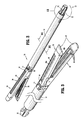
- FIG. 16 is a top view of the stitching end effector of FIG. 2 in a non-articulated configuration
- FIG. 17 is a top view of the stitching end effector shown in FIG. 16 in an articulated configuration with a longitudinal axis of the jaw assembly of the end effector defining an angle in relation to a longitudinal axis of the outer tube;
- FIG. 18 is an enlarged view of the indicated area of detail of FIG. 10 illustrating the cradle and the carriage of FIG. 10 with the cradle in a retracted configuration;
- FIG. 19 is a perspective view of the cradle of FIG. 18 with the carriage removed;
- FIG. 20 is an exploded view of the carriage and the cradle of FIG. 18 ;
- FIG. 21 is a perspective view of the cradle and the carriage of FIG. 18 with the cradle in an advanced configuration
- FIG. 22 is a perspective view of the cradle of FIG. 21 with the carriage removed;
- FIG. 23 is perspective view of another embodiment of a cradle drive finger in accordance with the present disclosure including a rack and pinion with the cradle in a retracted configuration;
- FIG. 24 is a perspective view of the cradle drive finger of FIG. 23 with the cradle in an advanced configuration
- FIG. 25 is a front perspective view of the stitching end effector of FIG. 2 with the upper jaw and the outer tube removed;
- FIG. 26 is an enlarged view of the indicated area of detail of FIG. 25 with the cradles in the retracted configuration and the needles within the needle slots of the lower jaw;
- FIG. 27 is an enlarged view of the indicated area of detail of FIG. 4 of the suture tensioner
- FIG. 28 is a view of the cradles of FIG. 26 in an advanced configuration with the needles extending from the needles slots of the lower jaw;
- FIG. 29 is a cross-sectional view of the stitching end effector taken along section line “ 29 - 29 ” of FIG. 16 ;
- FIG. 30 is a cross-sectional view of the stitching end effector of taken along section line “ 30 - 30 ” of FIG. 16 ;
- FIG. 31 is an enlarged view of the indicated area of detail of FIG. 30 ;
- FIG. 32 is a cross-sectional view of the stitching end effector illustrating the drive bar assembly advanced to a clamped position
- FIG. 33 is an enlarged view of the indicated area of detail of FIG. 32 ;
- FIG. 34-38 are a progression of longitudinal side cross-sectional views of the stitching end effector forming first, second, and third stitch loops as the drive bar assembly is manipulated in accordance with the present disclosure.
- the term “clinician” refers to a doctor, a nurse, or any other user, operator, or care provider and may include support personnel.
- proximal refers to the portion of the device or component thereof that is closest to the clinician and the term “distal” refers to the portion of the device or component thereof that is farthest from the clinician.
- an exemplary embodiment of a surgical instrument 1 is provided in accordance with present disclosure and includes a handle 10 , a stitching adaptor 20 , and a stitching loading unit 30 .
- the stitching loading unit 30 is configured to provide a line of stitches along the length of a jaw assembly as will be discussed in detail below.
- the handle 10 is a powered handle with one or more drive shafts (not shown) that rotate independently of one another.
- An exemplary embodiment of such a powered handle is disclosed in commonly owned and co-pending U.S. patent application Ser. No. 13/484,975 filed May 31, 2012, and now published as U.S. Patent Publication No. 2012/0253329 on Oct. 4, 2012, the contents of which are incorporated herein by reference in its entirety.
- the handle 10 may be a manually driven handle with one or more output shafts.
- the stitching adaptor 20 converts rotary motion of the drive shafts of the handle 10 into linear motion of selected drive bars to manipulate the stitching loading unit 30 as detailed below.
- the stitching adaptor 20 may include one or more gear trains (not shown) and one or more cams to convert the rotary motion of the drive shafts of the handle 10 into linear motion of the drive bars.
- An exemplary embodiment of such a stitching adaptor 20 is disclosed in commonly owned and co-pending U.S. patent application Ser. No. 14/279,928, filed May 16, 2014, the contents of which are incorporated herein by reference in its entirety.
- the stitching loading unit 30 includes an outer tube 32 , a jaw assembly 34 , and an inner housing 62 .
- a proximal end of the stitching loading unit 30 forms a connector 33 that engages the stitching adaptor 20 to secure the stitching loading unit 30 to the stitching adaptor 20 .
- the jaw assembly 34 includes a first or upper jaw member 36 and a second or lower jaw member 38 .
- the upper and lower jaw members 36 , 38 are moveable relative to one another between an open configuration ( FIG. 3 ) and a closed or clamped configuration ( FIG. 32 ).
- the upper jaw member 36 defines a longitudinal knife slot 96 a disposed along a longitudinal axis of the upper jaw member 36 .
- the lower jaw member 38 defines a longitudinal knife slot 96 b disposed along a longitudinal axis of the lower jaw member 38 .
- Each of the knife slots 96 a , 96 b extends through an inner or tissue contacting surface of a respective one of the jaw members 36 , 38 and an outer surface of a respective one of the jaw members 36 , 38 .
- Each of the knife slots 96 a , 96 b extends along the longitudinal axis of a respective one of the jaw members 36 , 38 from a proximal end thereof to a point adjacent a distal end of the respective jaw member 36 , 38 .
- the outer surface of each of the jaw members 36 , 38 defines a longitudinal beam groove 98 for receiving an upper or lower flange 97 of an I-beam 94 ( FIG. 33 ) as detailed below.
- the beam grooves 98 are disposed about the knife slots 96 a , 96 b and extend from the proximal end of each of the jaw members 36 , 38 to the distal end of the knife slots 96 a , 96 b.
- Each of the jaw members 36 , 38 further defines longitudinal needle slots 39 .
- the needles slots 39 are disposed in pairs on opposite sides of the knife slots 96 a , 96 b .
- the needle slots 39 of the lower jaw member 38 oppose the needle slots (not shown) of the upper jaw member 36 .
- the distal end of each of the jaw members 36 , 38 includes a blunt tip 37 and angled guide surface 37 a which are configured to atraumatically contact and guide tissue between the jaw members 36 , 38 .
- the inner housing 62 is generally cylindrical and is disposed within the outer tube 32 .
- the inner housing 62 may include an upper segment 62 a and a lower segment 62 b which are secured together using known fastening techniques (e.g., welding, gluing, etc.).
- the inner housing 62 slidably receives a drive bar assembly 40 and an extension rod assembly 70 .
- the drive bar assembly 40 includes upper carriage drive bars 41 ( FIG. 7 ), upper cradle drive bars 42 ( FIG. 7 ), lower carriage drive bars 43 ( FIG. 10 ), and lower cradle drive bars 44 ( FIG. 10 ).
- a stitching assembly 80 ( FIG. 6 ) is supported on a distal end of the drive bar assembly 80 and includes upper carriages 44 , upper cradles 45 , lower carriages 46 , and lower cradles 47 .
- Each of the drive bars 41 - 44 translate longitudinally in a stepwise manner (i.e., in a series of distinct steps) within the inner housing 62 to actuate the upper carriages 44 , upper cradles 45 , lower carriages 46 , and lower cradles 47 as detailed below.
- Each carriage drive bar 41 , 43 is positioned adjacent to and flanked by one of the cradle drive bars 42 , 44 ( FIGS. 9 and 10 ).
- a distal end of each of the upper carriage drive bars 41 is connected, either rigidly or releasably, to one of the upper carriages 45 such that longitudinal translation of a drive bar 41 effects longitudinal translation of the upper carriage 45 ( FIG. 7 ).
- a distal end of each of the lower carriage drive bars 43 is connected to one of the lower carriages 47 such that longitudinal translation of a drive bar 41 effects longitudinal translation of the lower carriage 47 .
- each of the upper carriage drive bars 41 is integrally formed with one of the upper carriages 45 and the distal end of each of the lower carriage drive bars 43 is integrally formed with one of the lower carriages 47 .
- the carriage drive bars 41 , 43 may be connected to corresponding carriages 45 , 47 in a rigid or releasable manner, for example integrally formed, snap fit, through glue, welding, molding, or via any variety of fasteners, or any other technique known to those of skill in the art.
- the proximal ends 41 a of the upper carriage drive bars 41 are connected to one another and the proximal ends 42 a of each of the upper cradle drive bars 42 are connected to one another (e.g., by welding or gluing) ( FIG. 7 ).
- the proximal ends 43 a ( FIG. 14 ) of each of the lower carriage drive bars 43 are connected to one another and the proximal ends 44 a ( FIG. 14 ) of each of the lower cradle drive bars 44 are connected to one another.
- proximal ends 41 a , 42 a , 43 a , 44 a may be connected to corresponding proximal ends 41 a , 42 a , 43 a , 44 a in a rigid or releasable manner, for example integrally formed, snap fit, through glue, welding, molding, or via any variety of fasteners, or any other technique known to those of skill in the art.
- the proximal ends 42 a of the upper cradle drive bars 42 are positioned distal to the proximal ends 41 a of the upper carriage drive bars 41 such that when the upper carriage drive bars 41 are advanced, the proximal ends 41 a of the upper carriage drive bars 41 engage the proximal ends 42 a of the upper cradle drive bars 42 to advance the upper cradle drive bars 42 .
- the proximal ends 44 a of the lower cradle drive bars 44 are positioned distal to the proximal ends 43 a of the lower carriage drive bars 43 such that when the lower carriage drive bars 43 are advanced, the proximal ends 43 a of the lower carriage drive bars 43 engage the proximal ends 44 a of the lower cradle drive bars 44 to advance the lower cradle drive bars 44 .
- the proximal ends 42 a of the upper cradle drive bars 42 may be positioned over the upper carriage drive bars 41 .
- the proximal ends 44 a of the lower cradle drive bars 44 may be positioned over the lower carriage drive bars 43 .
- the upper carriage drive bars 41 are connected to the knife drive member 95 such that longitudinal translation of the upper carriage drive bars 41 effects longitudinal translation of the knife drive member 95 .
- the lower carriage drive bars 43 may be connected to the knife drive member 95 such longitudinal translation of the lower carriage drive bars 43 effects longitudinal translation of member 95 .
- the carriage drive bars 41 , 43 may be connected to the knife drive member 95 in a rigid or releasable manner, for example integrally formed, snap fit, through glue, welding, molding, or via any variety of fasteners, or any other technique known to those of skill in the art.
- the proximal ends 41 a of the upper carriage drive bars 41 are connected to an upper carriage drive arm 41 b and the proximal ends 42 a of the upper cradle drive bars 42 are connected to an upper cradle drive arm 42 b ( FIG. 9 ).
- the upper carriage drive arm 41 b may be integrally formed with a proximal end 41 a of one of the upper carriage drive bars 41 and the upper cradle drive arm 42 b may be integrally formed with the proximal end 42 a of one of the upper cradle drive arms 42 b .
- the upper drive arms 41 b , 42 b may be welded or glued to a respective one of the upper drive bars 41 , 42 .
- proximal ends 43 a of the lower carriage drive bars 43 are connected to a lower carriage drive arm 43 b and the proximal ends 44 a of the lower cradle drive bars 44 are connected to a lower cradle drive arm 44 b ( FIG. 14 ).
- the proximal ends 41 a , 42 a , 43 a , 44 a of the drive bars 41 , 42 , 43 , 44 may be connected to corresponding drive arms 41 b , 42 b , 43 b , 44 b in a rigid or releasable manner, for example integrally formed, snap fit, through glue, welding, molding, or via any variety of fasteners, or any other technique known to those of skill in the art.
- the extension rod assembly 70 includes an upper carriage extension rod 72 , an upper cradle extension rod 74 , a lower carriage extension rod 76 , and a lower cradle extension rod 78 .
- the distal portion of each of the extension rods 72 , 74 , 76 , 78 is engagable with includes an engagement mechanism, such as notch 72 a , 74 a , 76 a , 78 a , configured to engage a respective one of the drive arms 41 b , 42 b , 43 b , 44 b such that movement, for example longitudinal translation, of the extension rods 72 , 74 , 76 , 78 effects movement, for example longitudinal translation, of each of the drive bars 41 , 42 , 43 , 44 , respectively.
- each of the extension rods 72 , 74 , 76 , 78 includes an extension wing 72 b , 74 b , 76 b , 78 b ( FIG. 10 ) positioned proximal to the proximal end of the outer tube 32 of loading unit 30 ( FIG. 1 ) adjacent the connector 33 .
- the connector 33 is configured to engage the adaptor 20 such that the adaptor 20 can manipulate the extension wings 72 b , 74 b 76 b , 78 b to operate the loading unit 30 . It is contemplated that the connector 33 may engage a handle or robotic controller which is configured to manipulate the extension wings 72 b , 74 b 76 b , 78 b to operate the loading unit 30 .
- the extension rods 72 , 74 , 76 , 78 are slidably disposed within the inner housing 62 of the loading unit 30 .
- the extension wings or tabs 72 b , 74 b , 76 b , 78 b of the carriage extension rods 72 , 74 , 76 , 78 extend beyond the outer surface of the inner housing 62 ( FIG. 13 ) to facilitate engagement by the adaptor 20 or other controller. It is also contemplated that the loading unit 30 may engage with the adaptor 20 in any manner known to those of skill in the art.
- the loading unit 30 may engage with the adaptor 20 by a bayonet-type connection, a J-hook type connection, a screw type connection, a spring-detent connection, or any combination thereof. Examples of such connections are disclosed in U.S. patent application Ser. No. 14/279,928, filed May 16, 2014, and U.S. Pat. No. 7,308,998, the contents of each are incorporated herein by reference in its entirety.
- the knife assembly 90 includes an I-beam 94 and a knife drive member 95 .
- the I-beam 94 has a vertical strut 97 a defining a knife 92 , and upper and lower flanges 97 interconnected by the vertical strut 97 a .
- the knife drive member 95 is coupled to a proximal portion of the I-beam 94 to advance and retract the I-beam 94 as detailed below.
- the knife drive member 95 is connected to the upper carriage drive bars 41 such that the knife drive member 95 is moved, such as advanced and retracted, in response to movement, such as advancement and retraction, of the upper carriage drive bars 41 .
- the stitching loading unit 30 includes an articulation assembly 50 that includes an articulation member 52 , a mounting member 53 , an articulation pivot 54 , and an articulation pin 56 .
- the articulation assembly 50 is configured to articulate the jaw assembly 34 about an axis perpendicular to a longitudinal axis of the loading unit 30 between a non-articulated configuration ( FIG. 16 ) and an articulated configuration ( FIG. 17 ).
- the articulation member 52 is slidably disposed within the inner housing 62 and outer tube 32 .
- An articulation bar arm 52 a is positioned at the proximal end of the articulation member 52 and is engaged by the adaptor 20 to facilitate longitudinal translation of the articulation member 52 upon actuation of the adaptor 20 .
- the distal end of the articulation member 52 includes an opening 52 b ( FIG. 4 ) that receives the articulation pin 56 ( FIG. 2 ).
- the articulation pin 56 passes through the opening 52 b into the mounting member 53 .
- the mounting member 53 is secured to the proximal end of the jaw assembly 34 and is pivotally connected to the inner housing 62 by the articulation pivot 54 .
- the articulation pin 56 which is offset from the longitudinal axis of the jaw member assembly 34 and articulation pivot 54 , pivots mounting member 53 to articulate the jaw assembly 34 ( FIG. 28 ). It is understood that as the articulation member 52 is retracted, the articulation pin 56 will pivot the mounting member 53 in the opposite direction to pivot the jaw assembly 34 in the opposite direction.
- Each of the carriage drive bars 41 , 43 , the cradle drive bars 42 , 44 , and the knife drive member 95 is flexible to facilitate actuation of the loading unit 30 when the jaw assembly 34 is articulated.
- an upper carriage drive bar 41 is connected to the upper carriage 45 and an upper cradle drive bar 42 is connected to the upper cradle 46 .
- Each upper carriage 45 includes a pair of distally located, spaced sidewalls 45 a .
- Each of the sidewalls 45 a defines an at least partially curved or arced cam slot 82 .
- the upper cradle 46 includes curved or arced cams 83 which protrude from each side of the upper cradle 46 .
- the upper cradle 46 defines suture passages 63 ( FIG. 20 ) which extend through the upper cradle 46 .
- a hollow curved or arced needle 81 is secured to the upper cradle 46 adjacent each suture passage 63 such that a suture 61 ( FIG. 2 ) may pass through the suture passage 63 and out a distal end of the needle 81 as detailed below.
- the arc of the cam slot 82 is substantially similar to the arc of the needles 81 .
- Each cam 83 of the upper cradle 46 is received within a respective cam slot 82 .
- a distal end of the upper carriage 45 defines plows 49 .
- One plow 49 is aligned with a distal end of each of the needles 81 .
- each cradle 46 may support a pair of needles 81 with a pair of sutures 61 associated with each pair of needles 81 as detailed below.
- the distal end of the upper cradle drive bar 42 includes a cradle drive finger 84 which is operatively associated with the upper cradle 46 .
- the cradle drive finger 84 translates the upper cradle 46 between a retracted configuration ( FIGS. 18 and 19 ) and an advanced configuration ( FIGS. 21 and 22 ).
- FIG. 19 the distal end of the cradle drive finger 84 is secured to an upper surface of the upper cradle 46 .
- the cam 83 of the cradle 46 is advanced through the arced cam slot 82 .
- a portion of the cradle drive finger 84 is curved or flexible to bend as the upper cradle 46 moves through a curved or arched path defined by the arced cam slot 82 .
- the cams 83 of the upper cradle 46 translate within the cam slots 82 of the upper carriage 45 to advance the needles 81 along an arced path.
- the body of each needle 81 tracks the distal end of the needle 81 such that the body of the needle 81 passes through a hole in tissue created by the distal end of the needle 81 .
- the body of each needle 81 passes back through the hole in the tissue such that the distal end of the needle 81 is withdrawn from the tissue.
- the lower carriages 47 and lower cradles 48 are manipulated in a similar manner to the upper carriage 45 and the upper cradle 46 described above.
- FIGS. 23 and 24 illustrate another embodiment of the presently disclosed cradle drive bar 42 ′ and cradle 46 .
- the cradle drive bar 41 ′ includes a cradle drive finger 84 ′ having a toothed rack 85 ′.
- the cradle 46 ′ supports a pinion 86 ′ which meshes with the toothed rack 85 ′.
- the cradle drive finger 84 ′ is substantially rigid such that as the cradle drive finger 84 ′ is longitudinally translated as a portion of the toothed rack 85 ′ remains engaged with the pinion 86 ′ of the cradle 46 ′ to transition the cradle 46 ′ between the retracted and advanced configurations. It is noted that the cradle 46 ′ is supported by the carriage 45 .
- the stitching loading unit 30 includes a suture storage and delivery assembly 60 disposed generally between the outer tube 32 and inner housing 62 .
- the suture storage and delivery assembly 60 includes sutures 61 and a suture tensioner 68 .
- the inner housing 62 defines suture recesses 64 which are separated by annular rings 64 a . Portions of sutures 61 are wound around the inner housing 62 within the suture recesses 64 .
- the sutures 61 associated with each pair of needles 81 of a respective cradle 46 , 48 are stored in pairs in each suture recess 64 .
- the inner housing 62 also defines conduit grooves 66 ( FIG.
- the suture tensioner 68 includes tensioning fingers 68 a ( FIG. 27 ) that engage the sutures 61 to prevent lengths of sutures 61 from inadvertently being drawn through the suture tensioner 68 .
- the suture tensioner 68 permits stitch loops to be formed as detailed below.
- the sutures 61 are fed from the suture tensioner 68 , through the suture passages 63 of cradle 46 , 48 , and through needles 81 .
- the conduits 65 prevent interference between the portion of the sutures 61 wound about the inner housing 62 and the portion of the suture 61 extending through the conduit grooves 65 .
- the needles 81 associated with the cradle are recessed within the needle slots 39 of a respective jaw member (e.g., lower jaw member 38 ) beneath a tissue engaging surface 100 of a respective jaw member 36 , 38 .
- the sutures 61 extend from the distal end of each needle 81 with a portion positioned along an outer surface of the needles 81 .
- the needles 81 extend from the needle slots 39 across the tissue engaging surface 100 of the respective jaw member 36 , 38 (e.g., lower jaw member 38 ).
- the operation of the stitching loading unit 30 is detailed in accordance with the present disclosure.
- a fully retracted position of the drive bar assembly 40 FIGS. 29-31
- the upper and lower jaws 36 , 38 are in an open configuration
- the upper and lower cradles 46 , 48 are in the retracted position
- the I-beam 94 is in its proximal-most position.
- the proximal end of the beam grooves 98 include ramps 99 ( FIG. 31 ).
- the flanges 97 of the I-beam 94 are positioned proximal to the ramps 99 of the beam grooves 98 .
- One of the upper and lower jaw members 36 , 38 may include a shield 31 ( FIG. 29 ) to prevent premature engagement of tissue with the knife 92 .
- the upper carriage drive bars 41 can be longitudinally advanced within the jaw assembly 34 to advance the knife drive member 95 .
- the upper carriage drive bars 41 are engaged with the upper cradle drive bars 42 such that when the upper carriage drive bars 41 are advanced the upper cradle drive bars 42 are also advanced.
- the knife drive member 95 advances the I-beam 94 to advance the flanges 97 along the beam grooves 98 of the upper and lower jaw members 36 , 38 as shown in FIGS. 32 and 33 .
- the flanges 97 of the I-beam 94 engage ramps 99 to cam the jaw members 36 , 38 to the clamped configuration.
- the drive bar assembly 40 ( FIG. 10 ) can be advanced further to translate the carriages 45 , 47 and the cradles 46 , 48 through the jaw assembly to create stitches with the sutures 61 in tissue clamped between the jaw members 36 , 38 .
- the carriages 45 , 47 and cradles 46 , 48 advance through the jaw assembly in a stepped manner.
- the carriage 45 and the cradle 46 are advanced together (a first step) to a first suture location.
- the cradle 46 is advanced and retracted relative to the carriage 45 to move a needle 81 through tissue to apply a suture loop to tissue.
- the carriage 45 and the cradle 46 are advanced together to a second suture location as detailed below. This process is repeated to form suture loops along the length of the jaw assembly 34 .
- the upper carriage 45 is advanced, which also advances the upper cradle 46 , to a position within the jaw assembly 34 .
- the upper cradle 46 is advanced to extend needle 81 a from the needle slot 39 a of the upper jaw member 36 , through tissue clamped within the jaw assembly 34 , and into the needle slot 39 b of the lower jaw member 38 .
- the suture 61 a which passes through needle 81 a , is pinched between the plow 49 a and the outer surface of needle 81 a as the needle 81 a is moved such that a length of suture 61 a is drawn through the suture tensioner ( FIG. 27 ).
- first stitch loop 161 ( FIG. 35 ) on the lower side of the tissue clamped within the jaw assembly 34 and adjacent the lower jaw member 38 . It is contemplated that a portion of the first stitch loop 161 may be disposed within the needle slot 39 b of the lower jaw member 38 .
- the upper cradle 46 is returned to the retracted position within the needle slot 39 a of the upper jaw member 36 leaving the first stitch loop 161 on the lower side of tissue clamped within the jaw assembly 34 and adjacent the lower jaw member 38 .
- the lower carriage 47 and the lower cradle 48 are advanced to locate the distal end of the needle 81 b of the lower cradle 48 in a position to pass through the first stitch loop 161 .
- the lower cradle 48 is advanced to extend the needle 81 b from the needle slot 39 b of the lower jaw member 38 , through the first stitch loop 161 , through tissue clamped within the jaw assembly, and into the needle slot 39 a of the upper jaw member 36 .
- the suture 61 b which passes through needle 81 b , is also pinched between the plow 49 b and the outer surface of the needle 81 b as the needle 81 b is extended to draw a length of suture 61 b through the suture tensioner ( FIG. 27 ).
- the length of suture 61 b forms a second stitch loop 162 on the upper side of tissue clamped within the jaw assembly 34 distal to the first stitch loop 161 and adjacent the upper jaw member 36 .
- the lower cradle 48 is returned to the retracted position within the lower jaw member 38 leaving the second stitch loop 162 on the upper side of tissue clamped within the jaw assembly 34 adjacent the upper jaw member 36 .
- the upper carriage 45 is advanced within the jaw assembly 34 (a second step) to also advance the upper cradle 46 to locate the distal end of needle 81 a of the upper cradle 46 in a position to pass through the second stitch loop 162 .
- the knife 92 is advanced to sever tissue clamped within the jaw assembly 34 . It will be appreciated that to reduce bleeding, the knife 92 trails the newly formed stitch loops (e.g., stitch loops 161 , 162 ) by at least one stitch loop.
- the upper cradle 46 is advanced to extend needle 81 a from the needle slot 39 a of the upper jaw member 36 , through the second stitch loop 162 , through tissue clamped within the jaw assembly 34 , and into the needle slot 39 b of the lower jaw member 38 .
- the suture 61 a is pinched between the plow 49 a and the outer surface of needle 81 a as the needle 81 a is extended to tension the first stitch loop 161 on the second stitch loop 162 and to draw an additional length of suture 61 a through the suture tensioner 68 ( FIG. 27 ).
- the additional length of the suture 61 a forms a third stitch loop 163 on the lower side of tissue clamped within the jaw assembly 34 .
- the tensioned stitch loops form stitches.
- This process is repeated to form additional stitches until the carriages 45 , 47 reach the end of the jaw members 36 , 38 or until a desired portion of tissue is stitched and cut (e.g., a body lumen is sutured and dissected).
- a desired portion of tissue e.g., a body lumen is sutured and dissected.
- the drive bar assembly 40 is returned to the fully retracted position to withdraw the flanges 97 of the I-beam 94 from the beam grooves 98 releasing the jaw members 36 , 38 from the clamped configuration.
- the suture tensioner 68 maintains tension in the sutures 61 to continuously stitch an additional portion of tissue clamped within the jaw assembly 34 .
- the excess of sutures 61 a , 61 b is trimmed.
- the jaw assembly 34 is advanced over additional tissue and the process is repeated until the desired portion of tissue is stitched and cut.
- stitching loading unit 30 may define openings in the outer tube 32 proximal to the suture tensioner 68 permitting lengths of the sutures 61 to be stored external to the stitching loading unit 30 . It will be understood that storing lengths of the sutures 61 external to the stitching loading unit 30 may permit the stitching loading unit 30 to be used indefinitely.
- jaw members 36 , 38 of the jaw assembly 34 are illustrated as being substantially linear, it is contemplated that jaw members 36 , 38 of jaw assembly 34 may be curved along a length thereof.
- An exemplary embodiment of such a curved jaw assembly is disclosed in commonly owned U.S. Pat. No. 7,988,028, the contents of which are incorporated herein by reference in its entirety.
Abstract
Description
Claims (20)
Priority Applications (6)
| Application Number | Priority Date | Filing Date | Title |
|---|---|---|---|
| US14/507,900 US9468434B2 (en) | 2014-06-03 | 2014-10-07 | Stitching end effector |
| CN201510295653.1A CN105266860B (en) | 2014-06-03 | 2015-06-02 | Suture end effector |
| ES15170195.0T ES2657791T3 (en) | 2014-06-03 | 2015-06-02 | Final effector to stitch |
| EP15170195.0A EP2952138B1 (en) | 2014-06-03 | 2015-06-02 | Stitching end effector |
| US15/271,831 US10245024B2 (en) | 2014-06-03 | 2016-09-21 | Stitching end effector |
| US16/279,096 US10966708B2 (en) | 2014-06-03 | 2019-02-19 | Stitching end effector |
Applications Claiming Priority (2)
| Application Number | Priority Date | Filing Date | Title |
|---|---|---|---|
| US201462006922P | 2014-06-03 | 2014-06-03 | |
| US14/507,900 US9468434B2 (en) | 2014-06-03 | 2014-10-07 | Stitching end effector |
Related Child Applications (1)
| Application Number | Title | Priority Date | Filing Date |
|---|---|---|---|
| US15/271,831 Continuation US10245024B2 (en) | 2014-06-03 | 2016-09-21 | Stitching end effector |
Publications (2)
| Publication Number | Publication Date |
|---|---|
| US20150342599A1 US20150342599A1 (en) | 2015-12-03 |
| US9468434B2 true US9468434B2 (en) | 2016-10-18 |
Family
ID=53365827
Family Applications (3)
| Application Number | Title | Priority Date | Filing Date |
|---|---|---|---|
| US14/507,900 Active 2035-03-18 US9468434B2 (en) | 2014-06-03 | 2014-10-07 | Stitching end effector |
| US15/271,831 Active 2035-06-24 US10245024B2 (en) | 2014-06-03 | 2016-09-21 | Stitching end effector |
| US16/279,096 Active 2035-04-03 US10966708B2 (en) | 2014-06-03 | 2019-02-19 | Stitching end effector |
Family Applications After (2)
| Application Number | Title | Priority Date | Filing Date |
|---|---|---|---|
| US15/271,831 Active 2035-06-24 US10245024B2 (en) | 2014-06-03 | 2016-09-21 | Stitching end effector |
| US16/279,096 Active 2035-04-03 US10966708B2 (en) | 2014-06-03 | 2019-02-19 | Stitching end effector |
Country Status (4)
| Country | Link |
|---|---|
| US (3) | US9468434B2 (en) |
| EP (1) | EP2952138B1 (en) |
| CN (1) | CN105266860B (en) |
| ES (1) | ES2657791T3 (en) |
Cited By (1)
| Publication number | Priority date | Publication date | Assignee | Title |
|---|---|---|---|---|
| US10245024B2 (en) | 2014-06-03 | 2019-04-02 | Covidien Lp | Stitching end effector |
Families Citing this family (7)
| Publication number | Priority date | Publication date | Assignee | Title |
|---|---|---|---|---|
| KR101743486B1 (en) | 2016-12-28 | 2017-06-05 | 김진성 | A suturing device |
| US10925597B2 (en) | 2016-12-29 | 2021-02-23 | Medtentia International Ltd Oy | Medical securing device for securing an object with a securing member |
| EP3342355B1 (en) * | 2016-12-29 | 2020-04-22 | Medtentia International Ltd Oy | Medical securing device for securing an object with a securing member |
| WO2018236843A2 (en) * | 2017-06-19 | 2018-12-27 | Harpoon Medical, Inc. | Method and apparatus for cardiac procedures |
| CN109480937B (en) * | 2018-11-23 | 2021-05-11 | 苏州英途康医疗科技有限公司 | Nail bin assembly and anastomat |
| CN109480936A (en) * | 2018-11-23 | 2019-03-19 | 苏州英途康医疗科技有限公司 | Nail bin groupware and stapler |
| WO2020176014A1 (en) * | 2019-02-25 | 2020-09-03 | Аркадий Вениаминович ДУБРОВСКИЙ | Surgical suturing device |
Citations (263)
| Publication number | Priority date | Publication date | Assignee | Title |
|---|---|---|---|---|
| US1822330A (en) | 1930-01-13 | 1931-09-08 | Ainslie George | Suturing instrument |
| US2327353A (en) | 1940-12-12 | 1943-08-24 | Singer Mfg Co | Instrument for suturing |
| US3073311A (en) | 1958-11-07 | 1963-01-15 | Nat Res Dev | Sewing device |
| US3123077A (en) | 1964-03-03 | Surgical suture | ||
| US4236470A (en) | 1979-01-17 | 1980-12-02 | Stenson Thomas K | Portable stitching device |
| US4417532A (en) | 1980-06-06 | 1983-11-29 | Janome Sawing Machine Industry Co., Ltd. | Suturing instrument for surgical operation |
| WO1987005122A1 (en) | 1986-02-24 | 1987-08-27 | Optical Radiation Corporation | Magnifying stereoscopic viewer |
| US4890615A (en) | 1987-11-05 | 1990-01-02 | Concept, Inc. | Arthroscopic suturing instrument |
| US4935027A (en) | 1989-08-21 | 1990-06-19 | Inbae Yoon | Surgical suture instrument with remotely controllable suture material advancement |
| US5037433A (en) | 1990-05-17 | 1991-08-06 | Wilk Peter J | Endoscopic suturing device and related method and suture |
| US5042707A (en) | 1990-10-16 | 1991-08-27 | Taheri Syde A | Intravascular stapler, and method of operating same |
| US5080663A (en) | 1990-09-26 | 1992-01-14 | Univerity College London | Sewing device |
| US5100430A (en) | 1990-08-31 | 1992-03-31 | Cordis Corporation | Biopsy forceps device having a ball and socket flexible coupling |
| US5100421A (en) | 1991-02-05 | 1992-03-31 | Cyprus Endosurgical Tools, Inc. | Christoudias curved needle suture assembly |
| US5209747A (en) | 1990-12-13 | 1993-05-11 | Knoepfler Dennis J | Adjustable angle medical forceps |
| US5271543A (en) | 1992-02-07 | 1993-12-21 | Ethicon, Inc. | Surgical anastomosis stapling instrument with flexible support shaft and anvil adjusting mechanism |
| US5300082A (en) | 1992-01-08 | 1994-04-05 | Sharpe Endosurgical Corporation | Endoneedle holder surgical instrument |
| EP0592244A2 (en) | 1992-10-09 | 1994-04-13 | Ethicon, Inc. | Endoscopic surgical stapling instrument with pivotable and rotatable staple cartridge |
| US5308353A (en) | 1992-08-31 | 1994-05-03 | Merrimac Industries, Inc. | Surgical suturing device |
| US5314445A (en) | 1991-02-15 | 1994-05-24 | Heidmueller Elke | Surgical instrument |
| US5330502A (en) | 1992-10-09 | 1994-07-19 | Ethicon, Inc. | Rotational endoscopic mechanism with jointed drive mechanism |
| US5336229A (en) | 1993-02-09 | 1994-08-09 | Laparomed Corporation | Dual ligating and dividing apparatus |
| US5350391A (en) | 1992-10-19 | 1994-09-27 | Benedetto Iacovelli | Laparoscopic instruments |
| US5358498A (en) | 1990-02-01 | 1994-10-25 | Deknatel Technology Corporation, Inc. | Needled suture |
| US5364408A (en) * | 1992-09-04 | 1994-11-15 | Laurus Medical Corporation | Endoscopic suture system |
| US5374277A (en) | 1992-10-09 | 1994-12-20 | Ethicon, Inc. | Surgical instrument |
| US5374275A (en) | 1993-03-25 | 1994-12-20 | Synvasive Technology, Inc. | Surgical suturing device and method of use |
| US5387221A (en) | 1991-01-17 | 1995-02-07 | Bisgaard; Therkel | Set of tools for suturing in deep surgical apertures or body cavities |
| US5389103A (en) | 1991-07-23 | 1995-02-14 | Kernforschungszentrum Karlsruhe Gmbh | Surgical stitching apparatus |
| US5391176A (en) | 1993-06-02 | 1995-02-21 | General Surgical Innovations, Inc. | Surgical instrument for tying a knot in a length of suture at a remote location |
| US5403342A (en) | 1992-04-23 | 1995-04-04 | United States Surgical Corporation | Articulating endoscopic surgical apparatus |
| US5405352A (en) | 1991-04-09 | 1995-04-11 | Weston; Peter V. | Suture knot, method for its formation and use, and knot forming apparatus |
| EP0647431A2 (en) | 1993-10-08 | 1995-04-12 | United States Surgical Corporation | Surgical suturing apparatus with loading mechanism |
| US5439478A (en) | 1990-05-10 | 1995-08-08 | Symbiosis Corporation | Steerable flexible microsurgical instrument with rotatable clevis |
| US5454823A (en) | 1991-09-30 | 1995-10-03 | Richardson; Philip | Suturing apparatus |
| US5454827A (en) | 1994-05-24 | 1995-10-03 | Aust; Gilbert M. | Surgical instrument |
| US5458609A (en) * | 1992-09-04 | 1995-10-17 | Laurus Medical Corporation | Surgical needle and retainer system |
| DE4423881C1 (en) | 1994-07-07 | 1995-10-26 | Karlsruhe Forschzent | Surgical sewing device |
| US5462560A (en) * | 1993-10-08 | 1995-10-31 | Tahoe Surgical Instruments | Double needle ligature device |
| US5472446A (en) | 1993-06-02 | 1995-12-05 | De La Torre; Roger A. | Surgical instrument for tying a knot in a length of suture at a remote location |
| US5478344A (en) | 1993-10-08 | 1995-12-26 | United States Surgical Corporation | Surgical suturing apparatus with loading mechanism |
| US5480406A (en) | 1994-10-07 | 1996-01-02 | United States Surgical Corporation | Method of employing surgical suturing apparatus to tie knots |
| US5496334A (en) | 1993-03-31 | 1996-03-05 | J. Stro/ bel & Sohne GmbH & Co. | Suturing apparatus |
| US5527323A (en) | 1993-06-02 | 1996-06-18 | General Surgical Innovations, Inc. | Surgical instrument for tying a knot in a length of suture at a remote location |
| US5540706A (en) | 1993-01-25 | 1996-07-30 | Aust; Gilbert M. | Surgical instrument |
| US5540703A (en) | 1993-01-06 | 1996-07-30 | Smith & Nephew Richards Inc. | Knotted cable attachment apparatus formed of braided polymeric fibers |
| US5540704A (en) * | 1992-09-04 | 1996-07-30 | Laurus Medical Corporation | Endoscopic suture system |
| US5549617A (en) | 1993-08-20 | 1996-08-27 | United States Surgical Corporation | Apparatus and method for applying and adjusting an anchoring device |
| US5549637A (en) | 1994-11-10 | 1996-08-27 | Crainich; Lawrence | Articulated medical instrument |
| US5562686A (en) | 1995-04-19 | 1996-10-08 | United States Surgical Corporation | Apparaus and method for suturing body tissue |
| US5564615A (en) | 1992-10-09 | 1996-10-15 | Ethicon, Inc. | Surgical instrument |
| US5571090A (en) | 1994-10-07 | 1996-11-05 | United States Surgical Corporation | Vascular suturing apparatus |
| US5573286A (en) | 1995-03-15 | 1996-11-12 | Rogozinski; Chaim | Knot |
| US5575799A (en) | 1995-03-30 | 1996-11-19 | United States Surgical Corporation | Articulating surgical apparatus |
| US5582617A (en) | 1993-07-21 | 1996-12-10 | Charles H. Klieman | Surgical instrument for endoscopic and general surgery |
| US5620415A (en) | 1993-01-29 | 1997-04-15 | Smith & Dyonics, Inc. | Surgical instrument |
| US5630825A (en) | 1995-04-27 | 1997-05-20 | De La Torre; Roger A. | Magazine for loading a needle onto a stitching instrument and for loading a length of suture onto a suture dispensing instrument |
| US5632751A (en) | 1995-07-28 | 1997-05-27 | Piraka; Hadi A. | Surgical suturing device |
| US5643294A (en) | 1993-03-01 | 1997-07-01 | United States Surgical Corporation | Surgical apparatus having an increased range of operability |
| US5643293A (en) | 1993-12-29 | 1997-07-01 | Olympus Optical Co., Ltd. | Suturing instrument |
| WO1997027807A1 (en) | 1996-01-31 | 1997-08-07 | Heartport, Inc. | Endoscopic suturing devices and methods |
| US5662666A (en) | 1995-11-13 | 1997-09-02 | Takamasa Onuki | Ligative suturer |
| US5674230A (en) | 1993-10-08 | 1997-10-07 | United States Surgical Corporation | Surgical suturing apparatus with locking mechanisms |
| US5681331A (en) | 1993-06-02 | 1997-10-28 | De La Torre; Roger A. | Surgical instrument for tying a knot in a length of suture at a remote location |
| US5702408A (en) | 1996-07-17 | 1997-12-30 | Ethicon Endo-Surgery, Inc. | Articulating surgical instrument |
| US5715942A (en) | 1996-11-15 | 1998-02-10 | Li Medical Technologies, Inc. | Package and holder for suture anchor with sutures and surgical needles attacked |
| US5728109A (en) | 1997-04-08 | 1998-03-17 | Ethicon Endo-Surgery, Inc. | Surgical knot and method for its formation |
| US5728113A (en) | 1994-10-07 | 1998-03-17 | United States Surgical Corporation | Endoscopic vascular suturing apparatus |
| US5730747A (en) | 1995-06-07 | 1998-03-24 | Smith & Nephew, Inc. | Suture passing forceps |
| WO1998011829A1 (en) | 1996-09-23 | 1998-03-26 | Symbiosis Corporation | Automatic needle-passer suturing instrument |
| WO1998011814A2 (en) | 1996-09-20 | 1998-03-26 | United States Surgical Corporation | Coil fastener applier and remover |
| US5749898A (en) | 1997-04-08 | 1998-05-12 | Ethicon Endo-Surgery, Inc. | Suture cartridge assembly for a surgical knot |
| US5752973A (en) | 1994-10-18 | 1998-05-19 | Archimedes Surgical, Inc. | Endoscopic surgical gripping instrument with universal joint jaw coupler |
| US5755729A (en) | 1995-04-27 | 1998-05-26 | General Surgical Innovations, Inc. | Magazine for loading a needle and a length of suture onto a surgical instrument |
| US5759188A (en) | 1996-11-27 | 1998-06-02 | Yoon; Inbae | Suturing instrument with rotatably mounted needle driver and catcher |
| US5766196A (en) | 1994-06-06 | 1998-06-16 | Tnco, Inc. | Surgical instrument with steerable distal end |
| US5779646A (en) | 1995-02-28 | 1998-07-14 | E.P. Technologies Inc. | Deflectable biopsy catheter |
| US5792153A (en) | 1994-03-23 | 1998-08-11 | University College London | Sewing device |
| US5792165A (en) | 1993-07-21 | 1998-08-11 | Charles H. Klieman | Endoscopic instrument with detachable end effector |
| US5797928A (en) | 1995-01-20 | 1998-08-25 | Olympus Optical Co., Ltd. | Ligating apparatus |
| US5797537A (en) | 1996-02-20 | 1998-08-25 | Richard-Allan Medical Industries, Inc. | Articulated surgical instrument with improved firing mechanism |
| US5797927A (en) | 1995-09-22 | 1998-08-25 | Yoon; Inbae | Combined tissue clamping and suturing instrument |
| US5814069A (en) | 1997-04-08 | 1998-09-29 | Ethicon Endo-Surgery, Inc. | Load assist device for a suture cartridge |
| US5817119A (en) | 1993-07-21 | 1998-10-06 | Charles H. Klieman | Surgical instrument for endoscopic and general surgery |
| US5827323A (en) | 1993-07-21 | 1998-10-27 | Charles H. Klieman | Surgical instrument for endoscopic and general surgery |
| US5843126A (en) | 1997-08-15 | 1998-12-01 | Jameel; Irfan M. | Multiple surgical suture application |
| WO1998053745A1 (en) | 1997-05-27 | 1998-12-03 | United States Surgical Corporation | Stitching devices for heart valve replacement surgery |
| US5860990A (en) * | 1995-08-24 | 1999-01-19 | Nr Medical, Inc. | Method and apparatus for suturing |
| US5865836A (en) | 1996-09-20 | 1999-02-02 | United States Surgical Corporation | Needle-suture combination |
| US5876412A (en) | 1997-06-06 | 1999-03-02 | Piraka; Hadi A. | Surgical suturing device |
| WO1999015090A1 (en) | 1997-09-24 | 1999-04-01 | Smith & Nephew, Inc. | Steerable surgical instrument |
| US5893592A (en) | 1997-04-08 | 1999-04-13 | Ethicon Endo-Surgery, Inc. | Partially tied surgical knot |
| WO1999018859A1 (en) | 1997-10-10 | 1999-04-22 | Origin Medsystems, Inc. | Endoscopic surgical instrument for rotational manipulation |
| US5897563A (en) | 1997-10-08 | 1999-04-27 | Ethicon Endo-Surgery, Inc. | Method for using a needle holder to assist in suturing |
| US5906630A (en) | 1998-06-30 | 1999-05-25 | Boston Scientific Limited | Eccentric surgical forceps |
| US5911727A (en) | 1996-02-20 | 1999-06-15 | Cardiothoracic Systems, Inc. | Stitcher |
| US5928136A (en) | 1997-02-13 | 1999-07-27 | Karl Storz Gmbh & Co. | Articulated vertebra for endoscopes and method to make it |
| US5931855A (en) | 1997-05-21 | 1999-08-03 | Frank Hoffman | Surgical methods using one-way suture |
| US5938668A (en) | 1994-10-07 | 1999-08-17 | United States Surgical | Surgical suturing apparatus |
| US5941430A (en) | 1997-03-10 | 1999-08-24 | Clover Mfg. Co., Ltd. | Holder for sewing needles |
| US5947983A (en) | 1998-03-16 | 1999-09-07 | Boston Scientific Corporation | Tissue cutting and stitching device and method |
| US5947982A (en) | 1997-04-02 | 1999-09-07 | Smith & Nephew, Inc. | Suture-passing forceps |
| US5954731A (en) | 1997-07-29 | 1999-09-21 | Yoon; Inbae | Surgical instrument with multiple rotatably mounted spreadable end effectors |
| US5957937A (en) | 1996-11-27 | 1999-09-28 | Yoon; Inbae | Suturing instrument with spreadable needle holder mounted for arcuate movement |
| US5980538A (en) | 1997-09-09 | 1999-11-09 | Werner Fuchs | Surgical suturing instrument |
| US5984932A (en) | 1996-11-27 | 1999-11-16 | Yoon; Inbae | Suturing instrument with one or more spreadable needle holders mounted for arcuate movement |
| US5993467A (en) | 1996-11-27 | 1999-11-30 | Yoon; Inbae | Suturing instrument with rotatably mounted spreadable needle holder |
| US5993466A (en) | 1997-06-17 | 1999-11-30 | Yoon; Inbae | Suturing instrument with multiple rotatably mounted spreadable needle holders |
| US5997565A (en) | 1997-01-16 | 1999-12-07 | Asahi Kogaku Kogyo Kabushiki Kaisha | Forceps for an endoscopic operation |
| US6004332A (en) | 1997-05-01 | 1999-12-21 | Yoon; Inbae | Suturing instrument with multiple rotatably mounted offset needle holders and method of using the same |
| US6017358A (en) | 1997-05-01 | 2000-01-25 | Inbae Yoon | Surgical instrument with multiple rotatably mounted offset end effectors |
| US6027522A (en) | 1998-06-02 | 2000-02-22 | Boston Scientific Corporation | Surgical instrument with a rotatable distal end |
| US6051006A (en) | 1999-04-12 | 2000-04-18 | Smith & Nephew, Inc. | Suture-passing forceps |
| US6071289A (en) | 1999-03-15 | 2000-06-06 | Ethicon Endo-Surgery, Inc. | Surgical device for suturing tissue |
| US6077287A (en) | 1997-06-11 | 2000-06-20 | Endius Incorporated | Surgical instrument |
| US6080180A (en) | 1997-05-01 | 2000-06-27 | Yoon; Inbae | Surgical instrument with rotatably mounted offset end effector and method of using the same |
| US6086601A (en) | 1998-04-29 | 2000-07-11 | Yoon; Inbae | Instrument and method for suturing anatomical tissue and tying suture material |
| US6119913A (en) | 1996-06-14 | 2000-09-19 | Boston Scientific Corporation | Endoscopic stapler |
| US6126665A (en) | 1997-05-01 | 2000-10-03 | Yoon; Inbae | Surgical instrument with arcuately movable offset end effectors and method of using the same |
| US6126666A (en) | 1997-04-14 | 2000-10-03 | Forschungszcutrum Karlsruhe Gmbh | Device for inserting a surgical suture needle into an endoscopic suture apparatus |
| US6139563A (en) | 1997-09-25 | 2000-10-31 | Allegiance Corporation | Surgical device with malleable shaft |
| US6143005A (en) | 1997-05-01 | 2000-11-07 | Yoon; Inbae | Suturing instrument with rotatably mounted offset needle holder and method of using the same |
| WO2000067834A1 (en) | 1999-05-11 | 2000-11-16 | Zynergy Cardiovascular, Inc. | Steerable catheter |
| US6206893B1 (en) | 1993-11-08 | 2001-03-27 | Perclose, Inc. | Device and method for suturing of internal puncture sites |
| US6223100B1 (en) | 1992-01-21 | 2001-04-24 | Sri, International | Apparatus and method for performing computer enhanced surgery with articulated instrument |
| US6224614B1 (en) | 1998-06-17 | 2001-05-01 | Inbae Yoon | Suturing instrument with angled needle holder and method for use thereof |
| US6277132B1 (en) | 1997-10-24 | 2001-08-21 | Forschungszentrum Karlsruhe, Gmbh | Needle inserter with a needle protection device |
| US20010023352A1 (en) * | 1992-09-04 | 2001-09-20 | Gordon Norman S. | Suturing instruments and methods of use |
| WO2001074254A1 (en) | 2000-03-31 | 2001-10-11 | Coalescent Surgical, Inc. | Multiple bias surgical fastener |
| US6319262B1 (en) | 1996-04-30 | 2001-11-20 | Boston Scientific Corporation | Calculus removal |
| US6332889B1 (en) | 1998-08-27 | 2001-12-25 | Onux Medical, Inc. | Surgical suturing instrument and method of use |
| US20020010480A1 (en) | 1999-08-03 | 2002-01-24 | Sancoff Gregory E. | Surgical suturing instrument and method of use |
| US6346111B1 (en) | 1992-09-04 | 2002-02-12 | Scimed Life Systems, Inc. | Suturing instruments and methods of use |
| US6358259B1 (en) | 1992-09-04 | 2002-03-19 | University College London | Device for use in tying knots |
| US20020045908A1 (en) * | 1995-08-24 | 2002-04-18 | Nobles Anthony A. | Suturing device and method |
| US20020049453A1 (en) * | 2000-06-14 | 2002-04-25 | Nobles Anthony A. | Suturing method and apparatus |
| WO2002034147A1 (en) | 2000-10-24 | 2002-05-02 | Sdgi Holdings, Inc. | Rotation locking driver for image guided instruments |
| US20020065526A1 (en) | 2000-11-28 | 2002-05-30 | Ran Oren | Suturing instrument and method |
| US20020072702A1 (en) | 2000-11-13 | 2002-06-13 | Quay Steven C. | Devices and methods for obtaining mammary fluid samples for evaluating breast diseases, including cancer |
| US20020173800A1 (en) | 2001-05-21 | 2002-11-21 | Peter Dreyfuss | Suture passer |
| US6494888B1 (en) | 1999-06-22 | 2002-12-17 | Ndo Surgical, Inc. | Tissue reconfiguration |
| US20020198542A1 (en) | 2001-06-07 | 2002-12-26 | Tetsuya Yamamoto | Suturing device for endoscope |
| US20030009195A1 (en) | 1999-08-03 | 2003-01-09 | Field Frederic P. | Surgical suturing instrument and method of use |
| US6506196B1 (en) | 1999-06-22 | 2003-01-14 | Ndo Surgical, Inc. | Device and method for correction of a painful body defect |
| US20030014077A1 (en) | 2001-06-29 | 2003-01-16 | Leung Jeffrey C. | Suture method |
| US6517539B1 (en) | 1999-08-06 | 2003-02-11 | Scimed Life Systems, Inc. | Polypectomy snare having ability to actuate through tortuous path |
| US20030045891A1 (en) | 2001-08-31 | 2003-03-06 | Tetsuya Yamamoto | Endoscopic suturing instrument |
| WO2003017850A2 (en) | 2001-08-31 | 2003-03-06 | Quill Medical, Inc. | Method of forming barbs on a suture and apparatus for performing same |
| US6533795B1 (en) | 2000-04-11 | 2003-03-18 | Opus Medical, Inc | Dual function suturing apparatus and method |
| US6533796B1 (en) | 2000-10-11 | 2003-03-18 | Lsi Solutions, Inc. | Loader for surgical suturing instrument |
| US6569105B1 (en) | 2000-09-14 | 2003-05-27 | Syntheon, Llc | Rotatable and deflectable biopsy forceps |
| US20030105475A1 (en) | 2001-07-23 | 2003-06-05 | Sancoff Gregory E. | Surgical suturing instrument and method of use |
| US20030105476A1 (en) | 2001-09-14 | 2003-06-05 | Sancoff Gregory E. | Surgical suturing instrument and method of use |
| US20030114863A1 (en) | 2000-10-20 | 2003-06-19 | Field Frederic P. | Surgical suturing instrument and method of use |
| US6582450B2 (en) | 1999-12-02 | 2003-06-24 | Pentax Corporation | Endoscopic manipulating wire coupling structure |
| US20030116670A1 (en) | 2001-12-21 | 2003-06-26 | Gentry Dalvin Marshell | Portable Motorized Remote Controlled Hose Reel |
| US6596015B1 (en) | 1999-07-13 | 2003-07-22 | Loma Linda University Medical Center | Methods and apparatus for annealing sutures |
| US6638287B2 (en) | 2001-05-02 | 2003-10-28 | Novare Surgical Systems | Clamp having bendable shaft |
| US6663639B1 (en) | 1999-06-22 | 2003-12-16 | Ndo Surgical, Inc. | Methods and devices for tissue reconfiguration |
| US20030233107A1 (en) * | 2002-06-12 | 2003-12-18 | Scimed Life Systems, Inc. | Suturing instrument with multi-load cartridge |
| US6666854B1 (en) | 1999-06-25 | 2003-12-23 | La Precision | Endoscopic surgical instrument |
| US6676676B2 (en) | 2001-05-02 | 2004-01-13 | Novare Surgical Systems | Clamp having bendable shaft |
| US20040010245A1 (en) | 1999-06-22 | 2004-01-15 | Cerier Jeffrey C. | Method and devices for tissue reconfiguration |
| US20040060410A1 (en) | 2002-09-30 | 2004-04-01 | Leung Jeffrey C. | Barbed sutures |
| US20040068272A1 (en) | 1999-11-19 | 2004-04-08 | Sauer Jude S. | System for wound closure |
| US6719765B2 (en) | 2001-12-03 | 2004-04-13 | Bonutti 2003 Trust-A | Magnetic suturing system and method |
| US6719764B1 (en) | 2001-08-24 | 2004-04-13 | Scimed Life Systems, Inc. | Forward deploying suturing device and methods of use |
| US20040088003A1 (en) | 2002-09-30 | 2004-05-06 | Leung Jeffrey C. | Barbed suture in combination with surgical needle |
| US20040087976A1 (en) | 2002-08-29 | 2004-05-06 | Devries Robert B. | Devices and methods for fastening tissue layers |
| US20040092963A1 (en) | 2001-03-26 | 2004-05-13 | Philipp Moll | Surgical suturing machine |
| US20040092967A1 (en) | 2001-12-11 | 2004-05-13 | Sancoff Gregory E. | Surgical suturing instrument and method of use |
| US6743240B2 (en) | 2001-06-25 | 2004-06-01 | Ethicon Endo-Surgery, Inc. | Flexible surgical device having a rotatable end effector assembly |
| US6743239B1 (en) | 2000-05-25 | 2004-06-01 | St. Jude Medical, Inc. | Devices with a bendable tip for medical procedures |
| US6755843B2 (en) | 2000-09-29 | 2004-06-29 | Olympus Optical Co., Ltd. | Endoscopic suturing device |
| US6786913B1 (en) | 1999-02-01 | 2004-09-07 | Onux Medical, Inc. | Surgical suturing instrument and method of use |
| US20040181243A1 (en) | 2003-03-10 | 2004-09-16 | Scimed Life Systems, Inc. | Re-shapeable medical device |
| US20040193186A1 (en) | 2003-03-25 | 2004-09-30 | Kortenbach Juergen A. | Flexible housing element for a surgical tool |
| US20040199184A1 (en) | 2001-10-01 | 2004-10-07 | Brad Topper | Suturing apparatus and method |
| US6821285B2 (en) | 1999-06-22 | 2004-11-23 | Ndo Surgical, Inc. | Tissue reconfiguration |
| EP1481628A1 (en) | 2003-05-27 | 2004-12-01 | Olympus Corporation | Endoscope |
| US6835200B2 (en) | 1999-06-22 | 2004-12-28 | Ndo Surgical. Inc. | Method and devices for tissue reconfiguration |
| US6889116B2 (en) | 2000-09-29 | 2005-05-03 | Kabushiki Kaisha Toshiba | Manipulator |
| US20050096694A1 (en) | 2003-10-30 | 2005-05-05 | Woojin Lee | Surgical instrument |
| US20050126876A1 (en) | 2003-07-07 | 2005-06-16 | Simmons John M. | Release mechanism for enabling manual manipulation of a motorized C-arm |
| US20050165419A1 (en) | 2001-02-02 | 2005-07-28 | Sauer Jude S. | System for endoscopic suturing |
| US6936061B2 (en) | 2000-04-27 | 2005-08-30 | Olympus Corporation | Surgical operation instrument |
| US6936054B2 (en) | 2002-07-22 | 2005-08-30 | Boston Scientific Scimed, Inc. | Placing sutures |
| US20050256533A1 (en) | 2003-10-14 | 2005-11-17 | Roth Alex T | Single fold device for tissue fixation |
| US6972017B2 (en) | 1999-08-06 | 2005-12-06 | Scimed Life Systems, Inc. | Polypectomy snare having ability to actuate through tortuous path |
| US6981628B2 (en) | 2003-07-09 | 2006-01-03 | Ethicon Endo-Surgery, Inc. | Surgical instrument with a lateral-moving articulation control |
| US6991635B2 (en) | 2001-10-01 | 2006-01-31 | Nipro Corporation | Intracardiac suture device |
| US20060025817A1 (en) | 2004-07-28 | 2006-02-02 | Ethicon Endo-Surgery, Inc. | Electroactive polymer-based articulation mechanism for linear stapler |
| US20060036232A1 (en) | 2002-10-04 | 2006-02-16 | Tyco Healthcare Group Lp | Surgical suturing apparatus with measurement structure |
| US20060069396A1 (en) | 2004-09-20 | 2006-03-30 | Suturtek Incorporated | Apparatus and method for minimally invasive suturing |
| US7041111B2 (en) | 2002-08-02 | 2006-05-09 | Boston Scientific Scimed, Inc. | Placing sutures |
| US20060111209A1 (en) | 2004-11-23 | 2006-05-25 | Novare Surgical Systems, Inc. | Articulating mechanisms and link systems with torque transmission in remote manipulation of instruments and tools |
| US7052489B2 (en) | 2003-12-05 | 2006-05-30 | Scimed Life Systems, Inc. | Medical device with deflecting shaft and related methods of manufacture and use |
| WO2006061868A1 (en) | 2004-12-06 | 2006-06-15 | Promoitalia International Srl | Surgical thread for plastic, dermatologic, and reconstructive surgery and for surgical sutures |
| US7063710B2 (en) | 2002-04-15 | 2006-06-20 | Nipro Corporation | Intracardiac suture device |
| US7063715B2 (en) | 2002-07-11 | 2006-06-20 | Olympus Corporation | Endoscopic suture apparatus |
| US7107124B2 (en) | 1992-01-21 | 2006-09-12 | Sri International | Roll-pitch-roll wrist methods for minimally invasive robotic surgery |
| US20060235304A1 (en) | 2005-04-15 | 2006-10-19 | Harhen Edward P | Connectorized probe for transesophageal echocardiography |
| US20060253126A1 (en) | 2005-05-04 | 2006-11-09 | Bernard Medical, Llc | Endoluminal suturing device and method |
| US20060282091A1 (en) | 2005-06-13 | 2006-12-14 | Shelton Frederick E Iv | Adjustable vacuum chamber for a surgical suturing apparatus |
| US20060282093A1 (en) | 2005-06-13 | 2006-12-14 | Shelton Frederick E Iv | Surgical suturing apparatus with anti-backup system |
| US20070005110A1 (en) | 2005-06-29 | 2007-01-04 | Collier John P | Braided barbed suture |
| US7191900B2 (en) | 2003-06-03 | 2007-03-20 | Js Vascular, Inc. | Guide wire containment and dispensing apparatus |
| US7192437B2 (en) | 1999-03-17 | 2007-03-20 | Poly Med Inc | High strength fibers of l-lactide copolymers, ε-caprolactone, and trimethylene carbonate and absorbable medical constructs thereof |
| US7211093B2 (en) | 2004-01-14 | 2007-05-01 | Lsi Solutions, Inc. | Sew-right running stitch instrument |
| US7218972B2 (en) | 2003-04-07 | 2007-05-15 | Cardiac Pacemakers, Inc. | Extra strength suture sleeve |
| US7232448B2 (en) | 2004-06-17 | 2007-06-19 | Ethicon, Inc. - Usa | Minimally invasive stitching device |
| US7244260B2 (en) | 2001-09-18 | 2007-07-17 | Kosek Medical K.K. | Apparatus for holding and arranging threads in surgical operations |
| US20080071296A1 (en) | 2004-11-18 | 2008-03-20 | Kurt Klundt | Endoscopic Stitching Machine |
| WO2008042423A2 (en) | 2006-10-02 | 2008-04-10 | Hansen Medical, Inc. | Systems for three-dimensional ultrasound mapping |
| WO2008045333A2 (en) | 2006-10-05 | 2008-04-17 | Tyco Healthcare Group Lp | Flexible endoscopic stitching devices |
| EP1915966A1 (en) | 2006-10-25 | 2008-04-30 | Terumo Kabushiki Kaisha | Manipulator for medical use |
| EP1915957A2 (en) | 2006-10-25 | 2008-04-30 | Terumo Kabushiki Kaisha | Manipulator for medical use |
| US20080188868A1 (en) | 2006-12-01 | 2008-08-07 | Barry Weitzner | Direct drive endoscopy systems and methods |
| US20080312688A1 (en) | 2007-06-13 | 2008-12-18 | Jesse G Nawrocki | Bi-directional Barbed Suture |
| US7468068B2 (en) | 2004-06-30 | 2008-12-23 | Alwin Kolster | Suture for wound closure, tissue approximation, tissue support, suspension and/or fixation |
| EP2044890A1 (en) | 2007-10-05 | 2009-04-08 | Tyco Healthcare Group LP | Powered surgical stapling device |
| US7601164B2 (en) | 2004-04-07 | 2009-10-13 | Tze Liang Woffles Wu | Surgical thread |
| EP2133028A2 (en) | 2008-06-13 | 2009-12-16 | Tyco Healthcare Group LP | Endoscopic stitching devices |
| US7645284B2 (en) | 2002-04-04 | 2010-01-12 | Vascular Control Systems, Inc. | Doppler directed suturing and compression device and method |
| US7691112B2 (en) | 2003-09-11 | 2010-04-06 | Nmt Medical, Inc. | Devices, systems, and methods for suturing tissue |
| US7704261B2 (en) | 2004-04-07 | 2010-04-27 | Olympus Corporation | Ligature and suture device for medical application, ligature and suture system for medical application, and ligaturing and suturing method for medical application |
| US7708747B2 (en) | 2006-04-12 | 2010-05-04 | InTailor Surgical, Inc. | Endoscopic suturing and implant system |
| US7722630B1 (en) | 2004-11-09 | 2010-05-25 | Biomet Sports Medicine, Llc | Method and apparatus for passing a suture through tissue |
| US7731726B2 (en) | 2003-12-03 | 2010-06-08 | St. Jude Medical Puerto Rico Llc | Suture based vascular closure apparatus and method incorporating a pre-tied knot |
| US7736372B2 (en) | 2003-11-13 | 2010-06-15 | Usgi Medical, Inc. | Apparatus and methods for endoscopic suturing |
| US7758598B2 (en) | 2006-05-19 | 2010-07-20 | Ethicon Endo-Surgery, Inc. | Combination knotting element and suture anchor applicator |
| US7766925B2 (en) | 2005-06-13 | 2010-08-03 | Ethicon Endo-Surgery, Inc. | Surgical suturing apparatus |
| US7776059B2 (en) | 2001-06-28 | 2010-08-17 | H Randall Craig | Suturing method |
| US7780701B1 (en) | 2003-08-13 | 2010-08-24 | Biomet Sports Medicine, Llc | Suture anchor |
| US7784612B2 (en) | 2007-06-08 | 2010-08-31 | Seirin Corporation | Packaging container for acupuncture needles |
| US7798325B2 (en) | 2005-07-29 | 2010-09-21 | Groz-Beckerg KG | Package for felting needles |
| US7815659B2 (en) | 2005-11-15 | 2010-10-19 | Ethicon Endo-Surgery, Inc. | Suture anchor applicator |
| US7814630B2 (en) | 2006-11-17 | 2010-10-19 | Ethicon, Inc. | Apparatus and method for swaging needles |
| US7828812B2 (en) | 2005-06-13 | 2010-11-09 | Ethicon Endo-Surgery, Inc. | Surgical suturing apparatus with needle release system |
| US7833237B2 (en) | 2003-02-04 | 2010-11-16 | Lsi Solutions, Inc. | Instrument for assisting in the remote placement of tied surgical knots and trimming of suture away from the knot and method of use |
| US7837696B2 (en) | 1999-03-04 | 2010-11-23 | Abbott Laboratories | Articulating suturing device and method |
| US7842048B2 (en) | 2006-08-18 | 2010-11-30 | Abbott Laboratories | Articulating suture device and method |
| US7842047B2 (en) | 1999-03-04 | 2010-11-30 | Abbott Laboratories | Articulating suturing device and method |
| US7846170B2 (en) | 1999-03-04 | 2010-12-07 | Abbott Laboratories | Articulating suturing device and method |
| US7883519B2 (en) | 2004-07-06 | 2011-02-08 | Ran Oren | Suture manipulating instrument particularly useful with endoscopes |
| US7883517B2 (en) | 2005-08-08 | 2011-02-08 | Abbott Laboratories | Vascular suturing device |
| US7935128B2 (en) | 2003-05-21 | 2011-05-03 | Boston Scientific Scimed, Inc. | Remotely-reloadable suturing device |
| US7947052B2 (en) | 2006-09-15 | 2011-05-24 | Ethicon Endo-Surgery, Inc. | Suturing device with angled head |
| US7947053B2 (en) | 2006-10-10 | 2011-05-24 | Mckay Raymond G | Suturing device and technique |
| US7951157B2 (en) | 2000-05-19 | 2011-05-31 | C.R. Bard, Inc. | Tissue capturing and suturing device and method |
| EP2329773A1 (en) | 2009-12-02 | 2011-06-08 | Tyco Healthcare Group LP | Adapters for use between surgical handle assembly and surgical end effector |
| US7967842B2 (en) | 2007-06-01 | 2011-06-28 | Ethicon Endo-Surgery, Inc. | Integrated securement and closure apparatus |
| US7967832B2 (en) | 2002-05-01 | 2011-06-28 | Boston Scientific Scimed, Inc. | Tying knots |
| US7972344B2 (en) | 2007-02-13 | 2011-07-05 | Arthrex, Inc. | Suture passing instrument and method of passing suture |
| US7976552B2 (en) | 2003-07-02 | 2011-07-12 | Olympus Corporation | Ligation apparatus |
| US20120283754A1 (en) | 2011-05-06 | 2012-11-08 | Michael Murillo | Suture passer devices and methods |
| US20120310220A1 (en) | 2011-06-01 | 2012-12-06 | Tyco Healthcare Group Lp | Surgical Articulation Assembly |
| EP2586382A2 (en) | 2011-10-25 | 2013-05-01 | Covidien LP | Apparatus for endosopic procedures |
| EP2606834A2 (en) | 2011-12-20 | 2013-06-26 | Covidien LP | Hand held surgical handle assembly, surgical adapters for use between surgical handle assembly and surgical end effectors, and methods of use |
| US20140296880A1 (en) | 2011-03-07 | 2014-10-02 | Scott Heneveld | Suture passing devices and methods |
| US20140350576A1 (en) * | 2013-05-22 | 2014-11-27 | Endolutions, Llc | Apparatus and method for fascial closure device for laparoscopic trocar port site and surgery |
| US20150327850A1 (en) * | 2014-05-16 | 2015-11-19 | Covidien Lp | Adaptor for surgical instrument for converting rotary input to linear output |
| US20150342599A1 (en) * | 2014-06-03 | 2015-12-03 | Covidien Lp | Stitching End Effector |
Family Cites Families (7)
| Publication number | Priority date | Publication date | Assignee | Title |
|---|---|---|---|---|
| US5762256A (en) | 1995-08-28 | 1998-06-09 | United States Surgical Corporation | Surgical stapler |
| US20040087978A1 (en) * | 2002-08-27 | 2004-05-06 | Velez Juan Manuel | Surgical fascia closure instrument, guide and method |
| US7938839B2 (en) * | 2003-06-13 | 2011-05-10 | Symmetry Medical New Bedford, Inc | Interlocking trigger assembly for a suturing device |
| US9055943B2 (en) | 2007-09-21 | 2015-06-16 | Covidien Lp | Hand held surgical handle assembly, surgical adapters for use between surgical handle assembly and surgical end effectors, and methods of use |
| CN2768678Y (en) * | 2005-03-10 | 2006-04-05 | 渠时学 | Comb type holding needle with adjustable holder |
| US7988028B2 (en) | 2008-09-23 | 2011-08-02 | Tyco Healthcare Group Lp | Surgical instrument having an asymmetric dynamic clamping member |
| CN203280434U (en) * | 2013-05-22 | 2013-11-13 | 宁波市爱达维电器有限公司 | Disposable skin suturing instrument |
-
2014
- 2014-10-07 US US14/507,900 patent/US9468434B2/en active Active
-
2015
- 2015-06-02 ES ES15170195.0T patent/ES2657791T3/en active Active
- 2015-06-02 EP EP15170195.0A patent/EP2952138B1/en not_active Not-in-force
- 2015-06-02 CN CN201510295653.1A patent/CN105266860B/en not_active Expired - Fee Related
-
2016
- 2016-09-21 US US15/271,831 patent/US10245024B2/en active Active
-
2019
- 2019-02-19 US US16/279,096 patent/US10966708B2/en active Active
Patent Citations (330)
| Publication number | Priority date | Publication date | Assignee | Title |
|---|---|---|---|---|
| US3123077A (en) | 1964-03-03 | Surgical suture | ||
| US1822330A (en) | 1930-01-13 | 1931-09-08 | Ainslie George | Suturing instrument |
| US2327353A (en) | 1940-12-12 | 1943-08-24 | Singer Mfg Co | Instrument for suturing |
| US3073311A (en) | 1958-11-07 | 1963-01-15 | Nat Res Dev | Sewing device |
| US4236470A (en) | 1979-01-17 | 1980-12-02 | Stenson Thomas K | Portable stitching device |
| US4417532A (en) | 1980-06-06 | 1983-11-29 | Janome Sawing Machine Industry Co., Ltd. | Suturing instrument for surgical operation |
| WO1987005122A1 (en) | 1986-02-24 | 1987-08-27 | Optical Radiation Corporation | Magnifying stereoscopic viewer |
| US4890615B1 (en) | 1987-11-05 | 1993-11-16 | Linvatec Corporation | Arthroscopic suturing instrument |
| US4890615A (en) | 1987-11-05 | 1990-01-02 | Concept, Inc. | Arthroscopic suturing instrument |
| US4923461A (en) | 1987-11-05 | 1990-05-08 | Concept, Inc. | Method of arthroscopic suturing of tissue |
| US4923461B1 (en) | 1987-11-05 | 1994-10-18 | Linvatec Corp | Method of arthroscopic suturing of tissue |
| US4923461B2 (en) | 1987-11-05 | 1995-06-20 | Linvatec Corp | Method of arthroscopic suturing |
| US4935027A (en) | 1989-08-21 | 1990-06-19 | Inbae Yoon | Surgical suture instrument with remotely controllable suture material advancement |
| US5358498A (en) | 1990-02-01 | 1994-10-25 | Deknatel Technology Corporation, Inc. | Needled suture |
| US5439478A (en) | 1990-05-10 | 1995-08-08 | Symbiosis Corporation | Steerable flexible microsurgical instrument with rotatable clevis |
| US5037433A (en) | 1990-05-17 | 1991-08-06 | Wilk Peter J | Endoscopic suturing device and related method and suture |
| US5100430A (en) | 1990-08-31 | 1992-03-31 | Cordis Corporation | Biopsy forceps device having a ball and socket flexible coupling |
| US5080663A (en) | 1990-09-26 | 1992-01-14 | Univerity College London | Sewing device |
| US5042707A (en) | 1990-10-16 | 1991-08-27 | Taheri Syde A | Intravascular stapler, and method of operating same |
| US5209747A (en) | 1990-12-13 | 1993-05-11 | Knoepfler Dennis J | Adjustable angle medical forceps |
| US5387221A (en) | 1991-01-17 | 1995-02-07 | Bisgaard; Therkel | Set of tools for suturing in deep surgical apertures or body cavities |
| US5100421A (en) | 1991-02-05 | 1992-03-31 | Cyprus Endosurgical Tools, Inc. | Christoudias curved needle suture assembly |
| US5314445A (en) | 1991-02-15 | 1994-05-24 | Heidmueller Elke | Surgical instrument |
| US5405352A (en) | 1991-04-09 | 1995-04-11 | Weston; Peter V. | Suture knot, method for its formation and use, and knot forming apparatus |
| US5389103A (en) | 1991-07-23 | 1995-02-14 | Kernforschungszentrum Karlsruhe Gmbh | Surgical stitching apparatus |
| US5690653A (en) | 1991-09-30 | 1997-11-25 | Richardson; Philip | Suturing apparatus |
| US5454823A (en) | 1991-09-30 | 1995-10-03 | Richardson; Philip | Suturing apparatus |
| US5300082A (en) | 1992-01-08 | 1994-04-05 | Sharpe Endosurgical Corporation | Endoneedle holder surgical instrument |
| US7107124B2 (en) | 1992-01-21 | 2006-09-12 | Sri International | Roll-pitch-roll wrist methods for minimally invasive robotic surgery |
| US6223100B1 (en) | 1992-01-21 | 2001-04-24 | Sri, International | Apparatus and method for performing computer enhanced surgery with articulated instrument |
| US7248944B2 (en) | 1992-01-21 | 2007-07-24 | Institute Surgical, Inc | Roll-pitch-roll wrist methods for minimally invasive robotic surgery |
| US5271543A (en) | 1992-02-07 | 1993-12-21 | Ethicon, Inc. | Surgical anastomosis stapling instrument with flexible support shaft and anvil adjusting mechanism |
| US5403342A (en) | 1992-04-23 | 1995-04-04 | United States Surgical Corporation | Articulating endoscopic surgical apparatus |
| US5308353A (en) | 1992-08-31 | 1994-05-03 | Merrimac Industries, Inc. | Surgical suturing device |
| US5700272A (en) * | 1992-09-04 | 1997-12-23 | Laurus Medical Corporation | Endoscopic suture system |
| US5575800A (en) * | 1992-09-04 | 1996-11-19 | Laurus Medical Corporation | Endoscopic suture system |
| US5540704A (en) * | 1992-09-04 | 1996-07-30 | Laurus Medical Corporation | Endoscopic suture system |
| US20010023352A1 (en) * | 1992-09-04 | 2001-09-20 | Gordon Norman S. | Suturing instruments and methods of use |
| US5364408A (en) * | 1992-09-04 | 1994-11-15 | Laurus Medical Corporation | Endoscopic suture system |
| US5741277A (en) * | 1992-09-04 | 1998-04-21 | Laurus Medical Corporation | Endoscopic suture system |
| US5458609A (en) * | 1992-09-04 | 1995-10-17 | Laurus Medical Corporation | Surgical needle and retainer system |
| US6346111B1 (en) | 1992-09-04 | 2002-02-12 | Scimed Life Systems, Inc. | Suturing instruments and methods of use |
| US6358259B1 (en) | 1992-09-04 | 2002-03-19 | University College London | Device for use in tying knots |
| US5662664A (en) * | 1992-09-04 | 1997-09-02 | Laurus Medical Corporation | Endoscopic suture system |
| US20040059350A1 (en) * | 1992-09-04 | 2004-03-25 | Scimed Life Systems, Inc. | Suturing instruments and methods of use |
| US7033370B2 (en) * | 1992-09-04 | 2006-04-25 | Boston Scientific Scimed, Inc. | Suturing instruments and methods of use |
| US7060077B2 (en) * | 1992-09-04 | 2006-06-13 | Boston Scientific Scimed, Inc. | Suturing instruments and methods of use |
| US5330502A (en) | 1992-10-09 | 1994-07-19 | Ethicon, Inc. | Rotational endoscopic mechanism with jointed drive mechanism |
| US5374277A (en) | 1992-10-09 | 1994-12-20 | Ethicon, Inc. | Surgical instrument |
| US5564615A (en) | 1992-10-09 | 1996-10-15 | Ethicon, Inc. | Surgical instrument |
| EP0592244A2 (en) | 1992-10-09 | 1994-04-13 | Ethicon, Inc. | Endoscopic surgical stapling instrument with pivotable and rotatable staple cartridge |
| US5601224A (en) | 1992-10-09 | 1997-02-11 | Ethicon, Inc. | Surgical instrument |
| US5350391A (en) | 1992-10-19 | 1994-09-27 | Benedetto Iacovelli | Laparoscopic instruments |
| US5540703A (en) | 1993-01-06 | 1996-07-30 | Smith & Nephew Richards Inc. | Knotted cable attachment apparatus formed of braided polymeric fibers |
| US5628756A (en) | 1993-01-06 | 1997-05-13 | Smith & Nephew Richards Inc. | Knotted cable attachment apparatus formed of braided polymeric fibers |
| USRE39152E1 (en) | 1993-01-25 | 2006-06-27 | Endius Incorporated | Surgical instrument |
| US5540706A (en) | 1993-01-25 | 1996-07-30 | Aust; Gilbert M. | Surgical instrument |
| US5620415A (en) | 1993-01-29 | 1997-04-15 | Smith & Dyonics, Inc. | Surgical instrument |
| US5336229A (en) | 1993-02-09 | 1994-08-09 | Laparomed Corporation | Dual ligating and dividing apparatus |
| US5643294A (en) | 1993-03-01 | 1997-07-01 | United States Surgical Corporation | Surgical apparatus having an increased range of operability |
| US5374275A (en) | 1993-03-25 | 1994-12-20 | Synvasive Technology, Inc. | Surgical suturing device and method of use |
| US5496334A (en) | 1993-03-31 | 1996-03-05 | J. Stro/ bel & Sohne GmbH & Co. | Suturing apparatus |
| US5681331A (en) | 1993-06-02 | 1997-10-28 | De La Torre; Roger A. | Surgical instrument for tying a knot in a length of suture at a remote location |
| US5391176A (en) | 1993-06-02 | 1995-02-21 | General Surgical Innovations, Inc. | Surgical instrument for tying a knot in a length of suture at a remote location |
| US5472446A (en) | 1993-06-02 | 1995-12-05 | De La Torre; Roger A. | Surgical instrument for tying a knot in a length of suture at a remote location |
| US5527323A (en) | 1993-06-02 | 1996-06-18 | General Surgical Innovations, Inc. | Surgical instrument for tying a knot in a length of suture at a remote location |
| US5582617A (en) | 1993-07-21 | 1996-12-10 | Charles H. Klieman | Surgical instrument for endoscopic and general surgery |
| US5827323A (en) | 1993-07-21 | 1998-10-27 | Charles H. Klieman | Surgical instrument for endoscopic and general surgery |
| US5792165A (en) | 1993-07-21 | 1998-08-11 | Charles H. Klieman | Endoscopic instrument with detachable end effector |
| US5817119A (en) | 1993-07-21 | 1998-10-06 | Charles H. Klieman | Surgical instrument for endoscopic and general surgery |
| US5549617A (en) | 1993-08-20 | 1996-08-27 | United States Surgical Corporation | Apparatus and method for applying and adjusting an anchoring device |
| US5728107A (en) | 1993-10-08 | 1998-03-17 | United States Surgical Corporation | Surgical suturing apparatus with loading mechanism |
| US5674229A (en) | 1993-10-08 | 1997-10-07 | United States Surgical Corporation | Surgical suturing apparatus with loading mechanism |
| US5591181A (en) | 1993-10-08 | 1997-01-07 | United States Surgical Corporation | Surgical suturing apparatus with loading mechanism |
| US5871488A (en) | 1993-10-08 | 1999-02-16 | United States Surgical Corporation | Surgical suturing apparatus with locking mechanisms |
| US5462560A (en) * | 1993-10-08 | 1995-10-31 | Tahoe Surgical Instruments | Double needle ligature device |
| US5674230A (en) | 1993-10-08 | 1997-10-07 | United States Surgical Corporation | Surgical suturing apparatus with locking mechanisms |
| US5478344A (en) | 1993-10-08 | 1995-12-26 | United States Surgical Corporation | Surgical suturing apparatus with loading mechanism |
| EP0647431A2 (en) | 1993-10-08 | 1995-04-12 | United States Surgical Corporation | Surgical suturing apparatus with loading mechanism |
| US6206893B1 (en) | 1993-11-08 | 2001-03-27 | Perclose, Inc. | Device and method for suturing of internal puncture sites |
| US5643293A (en) | 1993-12-29 | 1997-07-01 | Olympus Optical Co., Ltd. | Suturing instrument |
| US5792153A (en) | 1994-03-23 | 1998-08-11 | University College London | Sewing device |
| US5454827A (en) | 1994-05-24 | 1995-10-03 | Aust; Gilbert M. | Surgical instrument |
| US5766196A (en) | 1994-06-06 | 1998-06-16 | Tnco, Inc. | Surgical instrument with steerable distal end |
| US5690652A (en) | 1994-07-07 | 1997-11-25 | Forschungezentrum Karlsruhe Gmbh | Surgical suturing device |
| DE4423881C1 (en) | 1994-07-07 | 1995-10-26 | Karlsruhe Forschzent | Surgical sewing device |
| US5480406A (en) | 1994-10-07 | 1996-01-02 | United States Surgical Corporation | Method of employing surgical suturing apparatus to tie knots |
| US5938668A (en) | 1994-10-07 | 1999-08-17 | United States Surgical | Surgical suturing apparatus |
| US5746751A (en) | 1994-10-07 | 1998-05-05 | United States Surgical Corporation | Vascular suturing apparatus |
| US5728113A (en) | 1994-10-07 | 1998-03-17 | United States Surgical Corporation | Endoscopic vascular suturing apparatus |
| US5571090A (en) | 1994-10-07 | 1996-11-05 | United States Surgical Corporation | Vascular suturing apparatus |
| US5752973A (en) | 1994-10-18 | 1998-05-19 | Archimedes Surgical, Inc. | Endoscopic surgical gripping instrument with universal joint jaw coupler |
| US5549637A (en) | 1994-11-10 | 1996-08-27 | Crainich; Lawrence | Articulated medical instrument |
| US5797928A (en) | 1995-01-20 | 1998-08-25 | Olympus Optical Co., Ltd. | Ligating apparatus |
| US5779646A (en) | 1995-02-28 | 1998-07-14 | E.P. Technologies Inc. | Deflectable biopsy catheter |
| US5573286A (en) | 1995-03-15 | 1996-11-12 | Rogozinski; Chaim | Knot |
| US5575799A (en) | 1995-03-30 | 1996-11-19 | United States Surgical Corporation | Articulating surgical apparatus |
| US5562686A (en) | 1995-04-19 | 1996-10-08 | United States Surgical Corporation | Apparaus and method for suturing body tissue |
| US5630825A (en) | 1995-04-27 | 1997-05-20 | De La Torre; Roger A. | Magazine for loading a needle onto a stitching instrument and for loading a length of suture onto a suture dispensing instrument |
| US5755729A (en) | 1995-04-27 | 1998-05-26 | General Surgical Innovations, Inc. | Magazine for loading a needle and a length of suture onto a surgical instrument |
| US5730747A (en) | 1995-06-07 | 1998-03-24 | Smith & Nephew, Inc. | Suture passing forceps |
| US5632751A (en) | 1995-07-28 | 1997-05-27 | Piraka; Hadi A. | Surgical suturing device |
| US8348962B2 (en) * | 1995-08-24 | 2013-01-08 | Nobles Medical Technologies, Inc. | Suturing device and method |
| US5860990A (en) * | 1995-08-24 | 1999-01-19 | Nr Medical, Inc. | Method and apparatus for suturing |
| US20070276413A1 (en) * | 1995-08-24 | 2007-11-29 | Nobles Anthony A | Suturing device and method |
| US6562052B2 (en) * | 1995-08-24 | 2003-05-13 | Sutura, Inc. | Suturing device and method |
| US20020045908A1 (en) * | 1995-08-24 | 2002-04-18 | Nobles Anthony A. | Suturing device and method |
| US8197510B2 (en) * | 1995-08-24 | 2012-06-12 | Nobles Medical Technologies, Inc. | Suturing device and method |
| US7090686B2 (en) * | 1995-08-24 | 2006-08-15 | Sutura, Inc. | Suturing device and method |
| US20070043385A1 (en) * | 1995-08-24 | 2007-02-22 | Nobles Anthony A | Suturing device and method |
| US20040006352A1 (en) * | 1995-08-24 | 2004-01-08 | Nobles Anthony A. | Suturing device and method |
| US5797927A (en) | 1995-09-22 | 1998-08-25 | Yoon; Inbae | Combined tissue clamping and suturing instrument |
| US5662666A (en) | 1995-11-13 | 1997-09-02 | Takamasa Onuki | Ligative suturer |
| WO1997027807A1 (en) | 1996-01-31 | 1997-08-07 | Heartport, Inc. | Endoscopic suturing devices and methods |
| US5797537A (en) | 1996-02-20 | 1998-08-25 | Richard-Allan Medical Industries, Inc. | Articulated surgical instrument with improved firing mechanism |
| US5911727A (en) | 1996-02-20 | 1999-06-15 | Cardiothoracic Systems, Inc. | Stitcher |
| US6319262B1 (en) | 1996-04-30 | 2001-11-20 | Boston Scientific Corporation | Calculus removal |
| US6119913A (en) | 1996-06-14 | 2000-09-19 | Boston Scientific Corporation | Endoscopic stapler |
| US5702408A (en) | 1996-07-17 | 1997-12-30 | Ethicon Endo-Surgery, Inc. | Articulating surgical instrument |
| WO1998011814A2 (en) | 1996-09-20 | 1998-03-26 | United States Surgical Corporation | Coil fastener applier and remover |
| US5865836A (en) | 1996-09-20 | 1999-02-02 | United States Surgical Corporation | Needle-suture combination |
| WO1998011829A1 (en) | 1996-09-23 | 1998-03-26 | Symbiosis Corporation | Automatic needle-passer suturing instrument |
| US5814054A (en) | 1996-09-23 | 1998-09-29 | Symbiosis Corporation | Automatic needle-passer suturing instrument |
| US5715942A (en) | 1996-11-15 | 1998-02-10 | Li Medical Technologies, Inc. | Package and holder for suture anchor with sutures and surgical needles attacked |
| US5993467A (en) | 1996-11-27 | 1999-11-30 | Yoon; Inbae | Suturing instrument with rotatably mounted spreadable needle holder |
| US5984932A (en) | 1996-11-27 | 1999-11-16 | Yoon; Inbae | Suturing instrument with one or more spreadable needle holders mounted for arcuate movement |
| US5759188A (en) | 1996-11-27 | 1998-06-02 | Yoon; Inbae | Suturing instrument with rotatably mounted needle driver and catcher |
| US5957937A (en) | 1996-11-27 | 1999-09-28 | Yoon; Inbae | Suturing instrument with spreadable needle holder mounted for arcuate movement |
| US5954733A (en) | 1996-11-27 | 1999-09-21 | Yoon; Inbae | Suturing instrument with rotatably mounted needle driver and catcher |
| US5997565A (en) | 1997-01-16 | 1999-12-07 | Asahi Kogaku Kogyo Kabushiki Kaisha | Forceps for an endoscopic operation |
| US5928136A (en) | 1997-02-13 | 1999-07-27 | Karl Storz Gmbh & Co. | Articulated vertebra for endoscopes and method to make it |
| US5941430A (en) | 1997-03-10 | 1999-08-24 | Clover Mfg. Co., Ltd. | Holder for sewing needles |
| US5947982A (en) | 1997-04-02 | 1999-09-07 | Smith & Nephew, Inc. | Suture-passing forceps |
| US5728109A (en) | 1997-04-08 | 1998-03-17 | Ethicon Endo-Surgery, Inc. | Surgical knot and method for its formation |
| US5749898A (en) | 1997-04-08 | 1998-05-12 | Ethicon Endo-Surgery, Inc. | Suture cartridge assembly for a surgical knot |
| US5893592A (en) | 1997-04-08 | 1999-04-13 | Ethicon Endo-Surgery, Inc. | Partially tied surgical knot |
| US5814069A (en) | 1997-04-08 | 1998-09-29 | Ethicon Endo-Surgery, Inc. | Load assist device for a suture cartridge |
| US6126666A (en) | 1997-04-14 | 2000-10-03 | Forschungszcutrum Karlsruhe Gmbh | Device for inserting a surgical suture needle into an endoscopic suture apparatus |
| US6004332A (en) | 1997-05-01 | 1999-12-21 | Yoon; Inbae | Suturing instrument with multiple rotatably mounted offset needle holders and method of using the same |
| US6126665A (en) | 1997-05-01 | 2000-10-03 | Yoon; Inbae | Surgical instrument with arcuately movable offset end effectors and method of using the same |
| US6143005A (en) | 1997-05-01 | 2000-11-07 | Yoon; Inbae | Suturing instrument with rotatably mounted offset needle holder and method of using the same |
| US6017358A (en) | 1997-05-01 | 2000-01-25 | Inbae Yoon | Surgical instrument with multiple rotatably mounted offset end effectors |
| US6080180A (en) | 1997-05-01 | 2000-06-27 | Yoon; Inbae | Surgical instrument with rotatably mounted offset end effector and method of using the same |
| US6214028B1 (en) | 1997-05-01 | 2001-04-10 | Inbae Yoon | Surgical instrument with multiple rotatably mounted offset end effectors and method of using the same |
| US6261307B1 (en) | 1997-05-01 | 2001-07-17 | Inbae Yoon | Method of using surgical instrument with rotatably mounted offset end effector |
| US5931855A (en) | 1997-05-21 | 1999-08-03 | Frank Hoffman | Surgical methods using one-way suture |
| US5908428A (en) | 1997-05-27 | 1999-06-01 | United States Surgical Corporation | Stitching devices for heart valve replacement surgery |
| WO1998053745A1 (en) | 1997-05-27 | 1998-12-03 | United States Surgical Corporation | Stitching devices for heart valve replacement surgery |
| US5876412A (en) | 1997-06-06 | 1999-03-02 | Piraka; Hadi A. | Surgical suturing device |
| US6077287A (en) | 1997-06-11 | 2000-06-20 | Endius Incorporated | Surgical instrument |
| US5993466A (en) | 1997-06-17 | 1999-11-30 | Yoon; Inbae | Suturing instrument with multiple rotatably mounted spreadable needle holders |
| US5954731A (en) | 1997-07-29 | 1999-09-21 | Yoon; Inbae | Surgical instrument with multiple rotatably mounted spreadable end effectors |
| US5843126A (en) | 1997-08-15 | 1998-12-01 | Jameel; Irfan M. | Multiple surgical suture application |
| US5980538A (en) | 1997-09-09 | 1999-11-09 | Werner Fuchs | Surgical suturing instrument |
| WO1999015090A1 (en) | 1997-09-24 | 1999-04-01 | Smith & Nephew, Inc. | Steerable surgical instrument |
| US6139563A (en) | 1997-09-25 | 2000-10-31 | Allegiance Corporation | Surgical device with malleable shaft |
| US5897563A (en) | 1997-10-08 | 1999-04-27 | Ethicon Endo-Surgery, Inc. | Method for using a needle holder to assist in suturing |
| US6171316B1 (en) | 1997-10-10 | 2001-01-09 | Origin Medsystems, Inc. | Endoscopic surgical instrument for rotational manipulation |
| WO1999018859A1 (en) | 1997-10-10 | 1999-04-22 | Origin Medsystems, Inc. | Endoscopic surgical instrument for rotational manipulation |
| US6663641B1 (en) | 1997-10-10 | 2003-12-16 | Origin Medsystems, Inc. | Endoscopic surgical instrument for rotational manipulation |
| US6277132B1 (en) | 1997-10-24 | 2001-08-21 | Forschungszentrum Karlsruhe, Gmbh | Needle inserter with a needle protection device |
| US5947983A (en) | 1998-03-16 | 1999-09-07 | Boston Scientific Corporation | Tissue cutting and stitching device and method |
| US6086601A (en) | 1998-04-29 | 2000-07-11 | Yoon; Inbae | Instrument and method for suturing anatomical tissue and tying suture material |
| US6027522A (en) | 1998-06-02 | 2000-02-22 | Boston Scientific Corporation | Surgical instrument with a rotatable distal end |
| US6224614B1 (en) | 1998-06-17 | 2001-05-01 | Inbae Yoon | Suturing instrument with angled needle holder and method for use thereof |
| US5906630A (en) | 1998-06-30 | 1999-05-25 | Boston Scientific Limited | Eccentric surgical forceps |
| US20020128666A1 (en) | 1998-08-27 | 2002-09-12 | Sancoff Gregory E. | Surgical suturing instrument and method of use |
| US6332889B1 (en) | 1998-08-27 | 2001-12-25 | Onux Medical, Inc. | Surgical suturing instrument and method of use |
| US20050085832A1 (en) | 1998-08-27 | 2005-04-21 | Dvl Acquisitions, Sub, Inc. | Surgical suturing instrument and method of use |
| US6786913B1 (en) | 1999-02-01 | 2004-09-07 | Onux Medical, Inc. | Surgical suturing instrument and method of use |
| US7850701B2 (en) | 1999-03-04 | 2010-12-14 | Abbott Laboratories | Articulating suturing device and method |
| US7846170B2 (en) | 1999-03-04 | 2010-12-07 | Abbott Laboratories | Articulating suturing device and method |
| US7837696B2 (en) | 1999-03-04 | 2010-11-23 | Abbott Laboratories | Articulating suturing device and method |
| US7842047B2 (en) | 1999-03-04 | 2010-11-30 | Abbott Laboratories | Articulating suturing device and method |
| US6071289A (en) | 1999-03-15 | 2000-06-06 | Ethicon Endo-Surgery, Inc. | Surgical device for suturing tissue |
| US7192437B2 (en) | 1999-03-17 | 2007-03-20 | Poly Med Inc | High strength fibers of l-lactide copolymers, ε-caprolactone, and trimethylene carbonate and absorbable medical constructs thereof |
| US6051006A (en) | 1999-04-12 | 2000-04-18 | Smith & Nephew, Inc. | Suture-passing forceps |
| WO2000067834A1 (en) | 1999-05-11 | 2000-11-16 | Zynergy Cardiovascular, Inc. | Steerable catheter |
| US6773441B1 (en) | 1999-06-22 | 2004-08-10 | Ndo Surgical, Inc. | Methods and devices for tissue reconfiguration |
| US6821285B2 (en) | 1999-06-22 | 2004-11-23 | Ndo Surgical, Inc. | Tissue reconfiguration |
| US6506196B1 (en) | 1999-06-22 | 2003-01-14 | Ndo Surgical, Inc. | Device and method for correction of a painful body defect |
| US6835200B2 (en) | 1999-06-22 | 2004-12-28 | Ndo Surgical. Inc. | Method and devices for tissue reconfiguration |
| US7153314B2 (en) | 1999-06-22 | 2006-12-26 | Ndo Surgical | Tissue reconfiguration |
| US6663639B1 (en) | 1999-06-22 | 2003-12-16 | Ndo Surgical, Inc. | Methods and devices for tissue reconfiguration |
| US6494888B1 (en) | 1999-06-22 | 2002-12-17 | Ndo Surgical, Inc. | Tissue reconfiguration |
| US20040010245A1 (en) | 1999-06-22 | 2004-01-15 | Cerier Jeffrey C. | Method and devices for tissue reconfiguration |
| US6666854B1 (en) | 1999-06-25 | 2003-12-23 | La Precision | Endoscopic surgical instrument |
| US6596015B1 (en) | 1999-07-13 | 2003-07-22 | Loma Linda University Medical Center | Methods and apparatus for annealing sutures |
| US20030171761A1 (en) | 1999-08-03 | 2003-09-11 | Sancoff Gregory E. | Surgical suturing instrument and method of use |
| US20020010480A1 (en) | 1999-08-03 | 2002-01-24 | Sancoff Gregory E. | Surgical suturing instrument and method of use |
| US20050043747A1 (en) | 1999-08-03 | 2005-02-24 | Field Frederic P. | Surgical suturing instrument and method of use |
| US20030009195A1 (en) | 1999-08-03 | 2003-01-09 | Field Frederic P. | Surgical suturing instrument and method of use |
| US6972017B2 (en) | 1999-08-06 | 2005-12-06 | Scimed Life Systems, Inc. | Polypectomy snare having ability to actuate through tortuous path |
| US6517539B1 (en) | 1999-08-06 | 2003-02-11 | Scimed Life Systems, Inc. | Polypectomy snare having ability to actuate through tortuous path |
| US20040068272A1 (en) | 1999-11-19 | 2004-04-08 | Sauer Jude S. | System for wound closure |
| US6582450B2 (en) | 1999-12-02 | 2003-06-24 | Pentax Corporation | Endoscopic manipulating wire coupling structure |
| WO2001074254A1 (en) | 2000-03-31 | 2001-10-11 | Coalescent Surgical, Inc. | Multiple bias surgical fastener |
| US7758597B1 (en) | 2000-04-11 | 2010-07-20 | Arthrocare Corporation | Dual function suturing apparatus and method |
| US6533795B1 (en) | 2000-04-11 | 2003-03-18 | Opus Medical, Inc | Dual function suturing apparatus and method |
| US6936061B2 (en) | 2000-04-27 | 2005-08-30 | Olympus Corporation | Surgical operation instrument |
| US7951157B2 (en) | 2000-05-19 | 2011-05-31 | C.R. Bard, Inc. | Tissue capturing and suturing device and method |
| US6743239B1 (en) | 2000-05-25 | 2004-06-01 | St. Jude Medical, Inc. | Devices with a bendable tip for medical procedures |
| US20020049453A1 (en) * | 2000-06-14 | 2002-04-25 | Nobles Anthony A. | Suturing method and apparatus |
| US20050228407A1 (en) * | 2000-06-14 | 2005-10-13 | Nobles Anthony A | Suturing method and apparatus |
| US6911034B2 (en) * | 2000-06-14 | 2005-06-28 | Sterilis, Inc. | Suturing method and apparatus |
| US6569105B1 (en) | 2000-09-14 | 2003-05-27 | Syntheon, Llc | Rotatable and deflectable biopsy forceps |
| US6755843B2 (en) | 2000-09-29 | 2004-06-29 | Olympus Optical Co., Ltd. | Endoscopic suturing device |
| US6889116B2 (en) | 2000-09-29 | 2005-05-03 | Kabushiki Kaisha Toshiba | Manipulator |
| US6533796B1 (en) | 2000-10-11 | 2003-03-18 | Lsi Solutions, Inc. | Loader for surgical suturing instrument |
| US20030114863A1 (en) | 2000-10-20 | 2003-06-19 | Field Frederic P. | Surgical suturing instrument and method of use |
| US7666194B2 (en) | 2000-10-20 | 2010-02-23 | Onux Medical, Inc. | Surgical suturing instrument and method of use |
| WO2002034147A1 (en) | 2000-10-24 | 2002-05-02 | Sdgi Holdings, Inc. | Rotation locking driver for image guided instruments |
| US20020072702A1 (en) | 2000-11-13 | 2002-06-13 | Quay Steven C. | Devices and methods for obtaining mammary fluid samples for evaluating breast diseases, including cancer |
| US20020065526A1 (en) | 2000-11-28 | 2002-05-30 | Ran Oren | Suturing instrument and method |
| US6997931B2 (en) | 2001-02-02 | 2006-02-14 | Lsi Solutions, Inc. | System for endoscopic suturing |
| US20050165419A1 (en) | 2001-02-02 | 2005-07-28 | Sauer Jude S. | System for endoscopic suturing |
| US20040092963A1 (en) | 2001-03-26 | 2004-05-13 | Philipp Moll | Surgical suturing machine |
| US6676676B2 (en) | 2001-05-02 | 2004-01-13 | Novare Surgical Systems | Clamp having bendable shaft |
| US6638287B2 (en) | 2001-05-02 | 2003-10-28 | Novare Surgical Systems | Clamp having bendable shaft |
| US20020173800A1 (en) | 2001-05-21 | 2002-11-21 | Peter Dreyfuss | Suture passer |
| US8292903B2 (en) * | 2001-05-21 | 2012-10-23 | Boston Scientific Scimed, Inc. | Suture passer |
| US7771438B2 (en) | 2001-05-21 | 2010-08-10 | Boston Scientific Scimed, Inc. | Suture passer |
| US20130030450A1 (en) * | 2001-05-21 | 2013-01-31 | Peter Dreyfuss | Suture passer |
| US20060052801A1 (en) * | 2001-05-21 | 2006-03-09 | Boston Scientific Scimed, Inc. | Suture passer |
| US20100268256A1 (en) * | 2001-05-21 | 2010-10-21 | Boston Scientific Scimed, Inc. | Suture passer |
| US6997932B2 (en) * | 2001-05-21 | 2006-02-14 | Boston Scientific Scimed, Inc. | Suture passer |
| US20020198542A1 (en) | 2001-06-07 | 2002-12-26 | Tetsuya Yamamoto | Suturing device for endoscope |
| US6743240B2 (en) | 2001-06-25 | 2004-06-01 | Ethicon Endo-Surgery, Inc. | Flexible surgical device having a rotatable end effector assembly |
| US7776059B2 (en) | 2001-06-28 | 2010-08-17 | H Randall Craig | Suturing method |
| US20030014077A1 (en) | 2001-06-29 | 2003-01-16 | Leung Jeffrey C. | Suture method |
| US6599310B2 (en) | 2001-06-29 | 2003-07-29 | Quill Medical, Inc. | Suture method |
| US7011668B2 (en) | 2001-07-23 | 2006-03-14 | Dvl Acquistion Sub, Inc. | Surgical suturing instrument and method of use |
| US20030105475A1 (en) | 2001-07-23 | 2003-06-05 | Sancoff Gregory E. | Surgical suturing instrument and method of use |
| US6719764B1 (en) | 2001-08-24 | 2004-04-13 | Scimed Life Systems, Inc. | Forward deploying suturing device and methods of use |
| US20030045891A1 (en) | 2001-08-31 | 2003-03-06 | Tetsuya Yamamoto | Endoscopic suturing instrument |
| WO2003017850A2 (en) | 2001-08-31 | 2003-03-06 | Quill Medical, Inc. | Method of forming barbs on a suture and apparatus for performing same |
| US7037315B2 (en) | 2001-09-14 | 2006-05-02 | Dvl Aquisition Sub, Inc. | Surgical suturing instrument and method of use |
| US20030105476A1 (en) | 2001-09-14 | 2003-06-05 | Sancoff Gregory E. | Surgical suturing instrument and method of use |
| US7244260B2 (en) | 2001-09-18 | 2007-07-17 | Kosek Medical K.K. | Apparatus for holding and arranging threads in surgical operations |
| US20040199184A1 (en) | 2001-10-01 | 2004-10-07 | Brad Topper | Suturing apparatus and method |
| US6991635B2 (en) | 2001-10-01 | 2006-01-31 | Nipro Corporation | Intracardiac suture device |
| US6719765B2 (en) | 2001-12-03 | 2004-04-13 | Bonutti 2003 Trust-A | Magnetic suturing system and method |
| US20040092967A1 (en) | 2001-12-11 | 2004-05-13 | Sancoff Gregory E. | Surgical suturing instrument and method of use |
| US20030116670A1 (en) | 2001-12-21 | 2003-06-26 | Gentry Dalvin Marshell | Portable Motorized Remote Controlled Hose Reel |
| US7645284B2 (en) | 2002-04-04 | 2010-01-12 | Vascular Control Systems, Inc. | Doppler directed suturing and compression device and method |
| US7063710B2 (en) | 2002-04-15 | 2006-06-20 | Nipro Corporation | Intracardiac suture device |
| US7967832B2 (en) | 2002-05-01 | 2011-06-28 | Boston Scientific Scimed, Inc. | Tying knots |
| US6955643B2 (en) | 2002-06-12 | 2005-10-18 | Boston Scientific Scimed, Inc. | Endoscopic suture instrument |
| US20030233108A1 (en) * | 2002-06-12 | 2003-12-18 | Scimed Life Systems, Inc. | Endoscopic suture instrument |
| US20030233107A1 (en) * | 2002-06-12 | 2003-12-18 | Scimed Life Systems, Inc. | Suturing instrument with multi-load cartridge |
| US20030233104A1 (en) | 2002-06-12 | 2003-12-18 | Scimed Life Systems, Inc. | Suturing instrument with deflectable head |
| US7063715B2 (en) | 2002-07-11 | 2006-06-20 | Olympus Corporation | Endoscopic suture apparatus |
| US7776066B2 (en) | 2002-07-11 | 2010-08-17 | Olympus Corporation | Endoscopic suture apparatus |
| US7815654B2 (en) | 2002-07-22 | 2010-10-19 | Boston Scientific Scimed, Inc. | Placing sutures |
| US6936054B2 (en) | 2002-07-22 | 2005-08-30 | Boston Scientific Scimed, Inc. | Placing sutures |
| US7833235B2 (en) | 2002-08-02 | 2010-11-16 | Boston Scientific Scimed, Inc. | Placing sutures |
| US7041111B2 (en) | 2002-08-02 | 2006-05-09 | Boston Scientific Scimed, Inc. | Placing sutures |
| US20040087976A1 (en) | 2002-08-29 | 2004-05-06 | Devries Robert B. | Devices and methods for fastening tissue layers |
| US20040060410A1 (en) | 2002-09-30 | 2004-04-01 | Leung Jeffrey C. | Barbed sutures |
| US20040088003A1 (en) | 2002-09-30 | 2004-05-06 | Leung Jeffrey C. | Barbed suture in combination with surgical needle |
| US20060036232A1 (en) | 2002-10-04 | 2006-02-16 | Tyco Healthcare Group Lp | Surgical suturing apparatus with measurement structure |
| US7833237B2 (en) | 2003-02-04 | 2010-11-16 | Lsi Solutions, Inc. | Instrument for assisting in the remote placement of tied surgical knots and trimming of suture away from the knot and method of use |
| US20040181243A1 (en) | 2003-03-10 | 2004-09-16 | Scimed Life Systems, Inc. | Re-shapeable medical device |
| US20040193186A1 (en) | 2003-03-25 | 2004-09-30 | Kortenbach Juergen A. | Flexible housing element for a surgical tool |
| US7218972B2 (en) | 2003-04-07 | 2007-05-15 | Cardiac Pacemakers, Inc. | Extra strength suture sleeve |
| US7935128B2 (en) | 2003-05-21 | 2011-05-03 | Boston Scientific Scimed, Inc. | Remotely-reloadable suturing device |
| EP1481628A1 (en) | 2003-05-27 | 2004-12-01 | Olympus Corporation | Endoscope |
| US7191900B2 (en) | 2003-06-03 | 2007-03-20 | Js Vascular, Inc. | Guide wire containment and dispensing apparatus |
| US7976552B2 (en) | 2003-07-02 | 2011-07-12 | Olympus Corporation | Ligation apparatus |
| US20050126876A1 (en) | 2003-07-07 | 2005-06-16 | Simmons John M. | Release mechanism for enabling manual manipulation of a motorized C-arm |
| US6981628B2 (en) | 2003-07-09 | 2006-01-03 | Ethicon Endo-Surgery, Inc. | Surgical instrument with a lateral-moving articulation control |
| US7780701B1 (en) | 2003-08-13 | 2010-08-24 | Biomet Sports Medicine, Llc | Suture anchor |
| US7691112B2 (en) | 2003-09-11 | 2010-04-06 | Nmt Medical, Inc. | Devices, systems, and methods for suturing tissue |
| US20050256533A1 (en) | 2003-10-14 | 2005-11-17 | Roth Alex T | Single fold device for tissue fixation |
| US20050096694A1 (en) | 2003-10-30 | 2005-05-05 | Woojin Lee | Surgical instrument |
| US7736372B2 (en) | 2003-11-13 | 2010-06-15 | Usgi Medical, Inc. | Apparatus and methods for endoscopic suturing |
| US7731726B2 (en) | 2003-12-03 | 2010-06-08 | St. Jude Medical Puerto Rico Llc | Suture based vascular closure apparatus and method incorporating a pre-tied knot |
| US7052489B2 (en) | 2003-12-05 | 2006-05-30 | Scimed Life Systems, Inc. | Medical device with deflecting shaft and related methods of manufacture and use |
| US7211093B2 (en) | 2004-01-14 | 2007-05-01 | Lsi Solutions, Inc. | Sew-right running stitch instrument |
| US7601164B2 (en) | 2004-04-07 | 2009-10-13 | Tze Liang Woffles Wu | Surgical thread |
| US7704261B2 (en) | 2004-04-07 | 2010-04-27 | Olympus Corporation | Ligature and suture device for medical application, ligature and suture system for medical application, and ligaturing and suturing method for medical application |
| US7232448B2 (en) | 2004-06-17 | 2007-06-19 | Ethicon, Inc. - Usa | Minimally invasive stitching device |
| US7468068B2 (en) | 2004-06-30 | 2008-12-23 | Alwin Kolster | Suture for wound closure, tissue approximation, tissue support, suspension and/or fixation |
| US7883519B2 (en) | 2004-07-06 | 2011-02-08 | Ran Oren | Suture manipulating instrument particularly useful with endoscopes |
| US20060025817A1 (en) | 2004-07-28 | 2006-02-02 | Ethicon Endo-Surgery, Inc. | Electroactive polymer-based articulation mechanism for linear stapler |
| US20060069396A1 (en) | 2004-09-20 | 2006-03-30 | Suturtek Incorporated | Apparatus and method for minimally invasive suturing |
| US7722630B1 (en) | 2004-11-09 | 2010-05-25 | Biomet Sports Medicine, Llc | Method and apparatus for passing a suture through tissue |
| US20080071296A1 (en) | 2004-11-18 | 2008-03-20 | Kurt Klundt | Endoscopic Stitching Machine |
| US20060111209A1 (en) | 2004-11-23 | 2006-05-25 | Novare Surgical Systems, Inc. | Articulating mechanisms and link systems with torque transmission in remote manipulation of instruments and tools |
| WO2006061868A1 (en) | 2004-12-06 | 2006-06-15 | Promoitalia International Srl | Surgical thread for plastic, dermatologic, and reconstructive surgery and for surgical sutures |
| US20060235304A1 (en) | 2005-04-15 | 2006-10-19 | Harhen Edward P | Connectorized probe for transesophageal echocardiography |
| US20060253126A1 (en) | 2005-05-04 | 2006-11-09 | Bernard Medical, Llc | Endoluminal suturing device and method |
| US7766925B2 (en) | 2005-06-13 | 2010-08-03 | Ethicon Endo-Surgery, Inc. | Surgical suturing apparatus |
| US20060282093A1 (en) | 2005-06-13 | 2006-12-14 | Shelton Frederick E Iv | Surgical suturing apparatus with anti-backup system |
| US7828812B2 (en) | 2005-06-13 | 2010-11-09 | Ethicon Endo-Surgery, Inc. | Surgical suturing apparatus with needle release system |
| US7887554B2 (en) | 2005-06-13 | 2011-02-15 | Ethicon Endo-Surgery, Inc. | Surgical suturing apparatus with needle position indicator |
| US20060282091A1 (en) | 2005-06-13 | 2006-12-14 | Shelton Frederick E Iv | Adjustable vacuum chamber for a surgical suturing apparatus |
| US20070005110A1 (en) | 2005-06-29 | 2007-01-04 | Collier John P | Braided barbed suture |
| US7798325B2 (en) | 2005-07-29 | 2010-09-21 | Groz-Beckerg KG | Package for felting needles |
| US7883517B2 (en) | 2005-08-08 | 2011-02-08 | Abbott Laboratories | Vascular suturing device |
| US7815659B2 (en) | 2005-11-15 | 2010-10-19 | Ethicon Endo-Surgery, Inc. | Suture anchor applicator |
| US7708747B2 (en) | 2006-04-12 | 2010-05-04 | InTailor Surgical, Inc. | Endoscopic suturing and implant system |
| US7758598B2 (en) | 2006-05-19 | 2010-07-20 | Ethicon Endo-Surgery, Inc. | Combination knotting element and suture anchor applicator |
| US7842048B2 (en) | 2006-08-18 | 2010-11-30 | Abbott Laboratories | Articulating suture device and method |
| US7947052B2 (en) | 2006-09-15 | 2011-05-24 | Ethicon Endo-Surgery, Inc. | Suturing device with angled head |
| WO2008042423A2 (en) | 2006-10-02 | 2008-04-10 | Hansen Medical, Inc. | Systems for three-dimensional ultrasound mapping |
| US20130317525A1 (en) | 2006-10-05 | 2013-11-28 | Covidien Lp | Flexible endoscopic stitching devices |
| US8747424B2 (en) | 2006-10-05 | 2014-06-10 | Covidien Lp | Flexible endoscopic stitching devices |
| WO2008045333A2 (en) | 2006-10-05 | 2008-04-17 | Tyco Healthcare Group Lp | Flexible endoscopic stitching devices |
| US7947053B2 (en) | 2006-10-10 | 2011-05-24 | Mckay Raymond G | Suturing device and technique |
| EP1915966A1 (en) | 2006-10-25 | 2008-04-30 | Terumo Kabushiki Kaisha | Manipulator for medical use |
| EP1915957A2 (en) | 2006-10-25 | 2008-04-30 | Terumo Kabushiki Kaisha | Manipulator for medical use |
| US7814630B2 (en) | 2006-11-17 | 2010-10-19 | Ethicon, Inc. | Apparatus and method for swaging needles |
| US20080188868A1 (en) | 2006-12-01 | 2008-08-07 | Barry Weitzner | Direct drive endoscopy systems and methods |
| US7972344B2 (en) | 2007-02-13 | 2011-07-05 | Arthrex, Inc. | Suture passing instrument and method of passing suture |
| US7967842B2 (en) | 2007-06-01 | 2011-06-28 | Ethicon Endo-Surgery, Inc. | Integrated securement and closure apparatus |
| US7784612B2 (en) | 2007-06-08 | 2010-08-31 | Seirin Corporation | Packaging container for acupuncture needles |
| US20080312688A1 (en) | 2007-06-13 | 2008-12-18 | Jesse G Nawrocki | Bi-directional Barbed Suture |
| EP2044890A1 (en) | 2007-10-05 | 2009-04-08 | Tyco Healthcare Group LP | Powered surgical stapling device |
| EP2133028A2 (en) | 2008-06-13 | 2009-12-16 | Tyco Healthcare Group LP | Endoscopic stitching devices |
| US20090312773A1 (en) | 2008-06-13 | 2009-12-17 | Ramiro Cabrera | Endoscopic stitching devices |
| EP2329773A1 (en) | 2009-12-02 | 2011-06-08 | Tyco Healthcare Group LP | Adapters for use between surgical handle assembly and surgical end effector |
| US20140296880A1 (en) | 2011-03-07 | 2014-10-02 | Scott Heneveld | Suture passing devices and methods |
| US20120283754A1 (en) | 2011-05-06 | 2012-11-08 | Michael Murillo | Suture passer devices and methods |
| US20120310220A1 (en) | 2011-06-01 | 2012-12-06 | Tyco Healthcare Group Lp | Surgical Articulation Assembly |
| EP2586382A2 (en) | 2011-10-25 | 2013-05-01 | Covidien LP | Apparatus for endosopic procedures |
| EP2606834A2 (en) | 2011-12-20 | 2013-06-26 | Covidien LP | Hand held surgical handle assembly, surgical adapters for use between surgical handle assembly and surgical end effectors, and methods of use |
| US20140350576A1 (en) * | 2013-05-22 | 2014-11-27 | Endolutions, Llc | Apparatus and method for fascial closure device for laparoscopic trocar port site and surgery |
| US20150327850A1 (en) * | 2014-05-16 | 2015-11-19 | Covidien Lp | Adaptor for surgical instrument for converting rotary input to linear output |
| US20150342599A1 (en) * | 2014-06-03 | 2015-12-03 | Covidien Lp | Stitching End Effector |
Non-Patent Citations (4)
| Title |
|---|
| European Search Report dated Oct. 7, 2015, issued in European Application No. 15167797. |
| European Search Report dated Sep. 3, 2015, issued in EP Application No. 15170195. |
| U.S. Appl. No. 14/279,928, filed May 16, 2014, inventor: Stanislaw Kostrzewski. |
| Zeiss, Carl, "Universal S 3B Stand", Sep. 15, 2006, XP055216369, http://www.ophthalword.decosmoshop/pix/a/media/28072015/Zeiss S3 Floor Stand User Manual.pdf. |
Cited By (2)
| Publication number | Priority date | Publication date | Assignee | Title |
|---|---|---|---|---|
| US10245024B2 (en) | 2014-06-03 | 2019-04-02 | Covidien Lp | Stitching end effector |
| US10966708B2 (en) | 2014-06-03 | 2021-04-06 | Covidien Lp | Stitching end effector |
Also Published As
| Publication number | Publication date |
|---|---|
| CN105266860A (en) | 2016-01-27 |
| US20190175167A1 (en) | 2019-06-13 |
| US10245024B2 (en) | 2019-04-02 |
| ES2657791T3 (en) | 2018-03-06 |
| US10966708B2 (en) | 2021-04-06 |
| US20150342599A1 (en) | 2015-12-03 |
| CN105266860B (en) | 2019-03-26 |
| EP2952138B1 (en) | 2018-01-03 |
| US20170007235A1 (en) | 2017-01-12 |
| EP2952138A1 (en) | 2015-12-09 |
Similar Documents
| Publication | Publication Date | Title |
|---|---|---|
| US10966708B2 (en) | Stitching end effector | |
| US9615824B2 (en) | Handle assembly for endoscopic suturing device | |
| US8628545B2 (en) | Endoscopic stitching devices | |
| US8795325B2 (en) | Handle assembly for articulated endoscopic instruments | |
| US20160302792A1 (en) | Method for tissue resection | |
| US20160015383A1 (en) | Needle for laparoscopic suturing instrument | |
| US10799234B2 (en) | Suturing loading unit | |
| CN108392234B (en) | Endoscopic suturing device | |
| CN107440753B (en) | Endoscopic stitching device | |
| US10729424B2 (en) | Loading fixture for use with endoscopic stitching device | |
| EP3563775B1 (en) | Port site closure instrument | |
| US11864752B2 (en) | Endoscopic stitching device for supporting suture needles in various orientations | |
| US11751866B2 (en) | Endoscopic stitching device having angled suture needle | |
| US20210322003A1 (en) | Endoscopic stitching device for single hand operation | |
| CN113712617A (en) | Multifunctional needle holding instrument | |
| CN217853130U (en) | Surgical stapling apparatus and reload for a surgical stapling apparatus | |
| CN214857060U (en) | Multifunctional needle holding instrument | |
| US20200337691A1 (en) | Port site incision closure device | |
| CA2716444A1 (en) | Handle assembly for endoscopic suturing device |
Legal Events
| Date | Code | Title | Description |
|---|---|---|---|
| AS | Assignment |
Owner name: COVIDIEN LP, MASSACHUSETTS Free format text: ASSIGNMENT OF ASSIGNORS INTEREST;ASSIGNOR:KOSTRZEWSKI, STANISLAW;REEL/FRAME:033898/0979 Effective date: 20140603 |
|
| STCF | Information on status: patent grant |
Free format text: PATENTED CASE |
|
| MAFP | Maintenance fee payment |
Free format text: PAYMENT OF MAINTENANCE FEE, 4TH YEAR, LARGE ENTITY (ORIGINAL EVENT CODE: M1551); ENTITY STATUS OF PATENT OWNER: LARGE ENTITY Year of fee payment: 4 |
|
| MAFP | Maintenance fee payment |
Free format text: PAYMENT OF MAINTENANCE FEE, 8TH YEAR, LARGE ENTITY (ORIGINAL EVENT CODE: M1552); ENTITY STATUS OF PATENT OWNER: LARGE ENTITY Year of fee payment: 8 |