CN103154766A - 用于光学测量设备的偏转镜组件和相应的光学测量设备 - Google Patents
用于光学测量设备的偏转镜组件和相应的光学测量设备 Download PDFInfo
- Publication number
- CN103154766A CN103154766A CN2011800484502A CN201180048450A CN103154766A CN 103154766 A CN103154766 A CN 103154766A CN 2011800484502 A CN2011800484502 A CN 2011800484502A CN 201180048450 A CN201180048450 A CN 201180048450A CN 103154766 A CN103154766 A CN 103154766A
- Authority
- CN
- China
- Prior art keywords
- mirror
- rotatable shaft
- deflecting
- driver element
- mirror unit
- Prior art date
- Legal status (The legal status is an assumption and is not a legal conclusion. Google has not performed a legal analysis and makes no representation as to the accuracy of the status listed.)
- Pending
Links
Images


Classifications
-
- G—PHYSICS
- G02—OPTICS
- G02B—OPTICAL ELEMENTS, SYSTEMS OR APPARATUS
- G02B5/00—Optical elements other than lenses
- G02B5/08—Mirrors
-
- G—PHYSICS
- G02—OPTICS
- G02B—OPTICAL ELEMENTS, SYSTEMS OR APPARATUS
- G02B26/00—Optical devices or arrangements for the control of light using movable or deformable optical elements
- G02B26/08—Optical devices or arrangements for the control of light using movable or deformable optical elements for controlling the direction of light
- G02B26/10—Scanning systems
- G02B26/105—Scanning systems with one or more pivoting mirrors or galvano-mirrors
-
- G—PHYSICS
- G01—MEASURING; TESTING
- G01S—RADIO DIRECTION-FINDING; RADIO NAVIGATION; DETERMINING DISTANCE OR VELOCITY BY USE OF RADIO WAVES; LOCATING OR PRESENCE-DETECTING BY USE OF THE REFLECTION OR RERADIATION OF RADIO WAVES; ANALOGOUS ARRANGEMENTS USING OTHER WAVES
- G01S17/00—Systems using the reflection or reradiation of electromagnetic waves other than radio waves, e.g. lidar systems
- G01S17/88—Lidar systems specially adapted for specific applications
- G01S17/93—Lidar systems specially adapted for specific applications for anti-collision purposes
-
- G—PHYSICS
- G01—MEASURING; TESTING
- G01S—RADIO DIRECTION-FINDING; RADIO NAVIGATION; DETERMINING DISTANCE OR VELOCITY BY USE OF RADIO WAVES; LOCATING OR PRESENCE-DETECTING BY USE OF THE REFLECTION OR RERADIATION OF RADIO WAVES; ANALOGOUS ARRANGEMENTS USING OTHER WAVES
- G01S7/00—Details of systems according to groups G01S13/00, G01S15/00, G01S17/00
- G01S7/48—Details of systems according to groups G01S13/00, G01S15/00, G01S17/00 of systems according to group G01S17/00
- G01S7/481—Constructional features, e.g. arrangements of optical elements
- G01S7/4817—Constructional features, e.g. arrangements of optical elements relating to scanning
-
- G—PHYSICS
- G02—OPTICS
- G02B—OPTICAL ELEMENTS, SYSTEMS OR APPARATUS
- G02B26/00—Optical devices or arrangements for the control of light using movable or deformable optical elements
- G02B26/08—Optical devices or arrangements for the control of light using movable or deformable optical elements for controlling the direction of light
-
- G—PHYSICS
- G01—MEASURING; TESTING
- G01C—MEASURING DISTANCES, LEVELS OR BEARINGS; SURVEYING; NAVIGATION; GYROSCOPIC INSTRUMENTS; PHOTOGRAMMETRY OR VIDEOGRAMMETRY
- G01C3/00—Measuring distances in line of sight; Optical rangefinders
- G01C3/02—Details
- G01C3/06—Use of electric means to obtain final indication
- G01C3/08—Use of electric radiation detectors
-
- G—PHYSICS
- G01—MEASURING; TESTING
- G01S—RADIO DIRECTION-FINDING; RADIO NAVIGATION; DETERMINING DISTANCE OR VELOCITY BY USE OF RADIO WAVES; LOCATING OR PRESENCE-DETECTING BY USE OF THE REFLECTION OR RERADIATION OF RADIO WAVES; ANALOGOUS ARRANGEMENTS USING OTHER WAVES
- G01S17/00—Systems using the reflection or reradiation of electromagnetic waves other than radio waves, e.g. lidar systems
- G01S17/02—Systems using the reflection of electromagnetic waves other than radio waves
- G01S17/06—Systems determining position data of a target
- G01S17/08—Systems determining position data of a target for measuring distance only
-
- G—PHYSICS
- G01—MEASURING; TESTING
- G01S—RADIO DIRECTION-FINDING; RADIO NAVIGATION; DETERMINING DISTANCE OR VELOCITY BY USE OF RADIO WAVES; LOCATING OR PRESENCE-DETECTING BY USE OF THE REFLECTION OR RERADIATION OF RADIO WAVES; ANALOGOUS ARRANGEMENTS USING OTHER WAVES
- G01S17/00—Systems using the reflection or reradiation of electromagnetic waves other than radio waves, e.g. lidar systems
- G01S17/88—Lidar systems specially adapted for specific applications
- G01S17/93—Lidar systems specially adapted for specific applications for anti-collision purposes
- G01S17/931—Lidar systems specially adapted for specific applications for anti-collision purposes of land vehicles
-
- G—PHYSICS
- G01—MEASURING; TESTING
- G01S—RADIO DIRECTION-FINDING; RADIO NAVIGATION; DETERMINING DISTANCE OR VELOCITY BY USE OF RADIO WAVES; LOCATING OR PRESENCE-DETECTING BY USE OF THE REFLECTION OR RERADIATION OF RADIO WAVES; ANALOGOUS ARRANGEMENTS USING OTHER WAVES
- G01S7/00—Details of systems according to groups G01S13/00, G01S15/00, G01S17/00
- G01S7/48—Details of systems according to groups G01S13/00, G01S15/00, G01S17/00 of systems according to group G01S17/00
- G01S7/481—Constructional features, e.g. arrangements of optical elements
- G01S7/4811—Constructional features, e.g. arrangements of optical elements common to transmitter and receiver
-
- G—PHYSICS
- G02—OPTICS
- G02B—OPTICAL ELEMENTS, SYSTEMS OR APPARATUS
- G02B26/00—Optical devices or arrangements for the control of light using movable or deformable optical elements
- G02B26/08—Optical devices or arrangements for the control of light using movable or deformable optical elements for controlling the direction of light
- G02B26/0816—Optical devices or arrangements for the control of light using movable or deformable optical elements for controlling the direction of light by means of one or more reflecting elements
-
- G—PHYSICS
- G02—OPTICS
- G02B—OPTICAL ELEMENTS, SYSTEMS OR APPARATUS
- G02B26/00—Optical devices or arrangements for the control of light using movable or deformable optical elements
- G02B26/08—Optical devices or arrangements for the control of light using movable or deformable optical elements for controlling the direction of light
- G02B26/10—Scanning systems
- G02B26/12—Scanning systems using multifaceted mirrors
- G02B26/121—Mechanical drive devices for polygonal mirrors
Landscapes
- Physics & Mathematics (AREA)
- General Physics & Mathematics (AREA)
- Engineering & Computer Science (AREA)
- Optics & Photonics (AREA)
- Computer Networks & Wireless Communication (AREA)
- Radar, Positioning & Navigation (AREA)
- Remote Sensing (AREA)
- Electromagnetism (AREA)
- Optical Radar Systems And Details Thereof (AREA)
- Mechanical Optical Scanning Systems (AREA)
- Mounting And Adjusting Of Optical Elements (AREA)
- Mechanical Light Control Or Optical Switches (AREA)
Abstract
本发明涉及一种用于光学测量设备的偏转镜组件(30),其具有至少一个镜单元(31、32)和驱动单元(33),所述镜单元布置在可旋转轴(34)上并包括至少一个偏转镜(31.1、31.2、32.1、32.2),所述驱动单元(33)驱动可旋转轴(34),以及涉及一种具有这样的偏转镜组件(30)的光学测量设备。为了使得必需的安装空间减少,所述至少一个镜单元(31、32)包括至少两个偏转镜(31.1、31.2、32.1、32.2),所述至少两个偏转镜布置在共用的水平面中,使得它们相对于可旋转轴(34)径向地间隔开,其中,驱动单元(33)至少部分地布置在两个偏转镜(31.1、31.2)之间的空间中。
Description
技术领域
本发明涉及一种在权利要求1的前序部分中提及的类型的用于光学测量设备的偏转镜装置,并涉及一种相应的具有这样的偏转镜装置的光学测量设备。
背景技术
从现有技术中已知扫描光学测量设备,称为激光扫描器,其根据光脉冲飞行时间方法来确定距在监测区域中检测的物体或障碍物的距离,该光学测量设备用于车辆,用于检测监测区域中的物体或障碍物。
专利说明书DE102005055572B4例如描述了一种扫描光学距离传感器。所描述的距离传感器包括作为光发送器的至少一个激光器、作为光接收器的至少一个检测器、和偏转单元,所述偏转单元使用第一镜将产生的激光辐射偏转到要测量的场景上,并使用第二镜将由物体散射回来的激光脉冲偏转到所述至少一个检测器上。这里,第一和第二镜布置在共用的可旋转轴上,该可旋转轴由驱动单元驱动。第一镜布置在第一保持器上,第二境布置在第二保持器上,具有相对于第一镜的轴向间距,而驱动单元布置在两个保持器之间。具有相关电子器件的所述至少一个激光器和所述至少一个检测器以直立方式布置。
发明内容
本发明的目的是开发一种在权利要求1的前序部分中提到的类型的用于光学测量设备的偏转镜装置,使得可以减少必需的安装空间,以及目的是指出一种相应的光学测量设备。
根据本发明通过用于激光扫描器的具有权利要求1的特征的偏转镜装置和通过具有权利要求10的特征的光学测量设备实现了该目标。有利地实现本发明的实施例的其他特征包含在从属权利要求中。
本发明实现的优势是,由于驱动单元布置在两个偏转镜之间的空间中,可以减少用于偏转镜装置的必需的安装空间。因此,特别地可以减少偏转镜装置的安装高度。
本发明的基本思想基于具有两个镜的镜单元的实现,所述两个镜布置为在水平面中相对于彼此间隔开,且驱动单元随后布置在所述两个镜之间。此外,在两侧安装镜单元可通过将镜布置在承载板或承载件本体上而更容易地实现。
根据本发明的一种用于光学测量设备的偏转镜装置包括至少一个镜单元和驱动单元,所述镜单元布置在可旋转轴上并包括至少一个偏转镜,所述驱动单元驱动可旋转轴。根据本发明,所述至少一个镜单元包括至少两个偏转镜,所述偏转镜布置为距可旋转轴有径向间距,而驱动单元至少部分地布置在两个偏转镜之间的空间中。
在根据本发明的装置的一个有利配置中,所述至少两个偏转镜布置在承载板上,而驱动单元布置在支撑板中的孔中。由此,可以更容易地实现镜单元的双侧安装以及可以减少旋转运动中的偏离。为了简化驱动单元在承载板中的孔中的布置,周向凸缘可以形成在孔的边缘处。
所述至少一个镜单元可例如配置为具有至少两个发送偏转镜的发送镜单元和/或配置为具有至少两个接收偏转镜的接收镜单元。
在根据本发明的装置的其他有利配置中,具有两个发送偏转镜的发送镜单元和具有两个接收偏转镜的接收镜单元布置在共用的可旋转轴上,使得它们相对于彼此轴向地间隔开,所述两个发送偏转镜布置在具有孔的承载板上以使得它们径向地间隔开,而驱动单元布置在两个发送偏转镜之间的空间中。所述两个接收偏转镜可在每种情况下固定在承载件本体的侧部上,使得它们径向地间隔开。由此,可以更容易地实现接收镜单元的双侧安装以及可以减少接收镜单元的旋转运动中的偏离。为了感测当前旋转角,编码盘可以布置在发送镜单元和接收镜单元之间处于承载板之下,所述编码盘可被评估以确定可旋转轴的旋转角。
在根据本发明的装置的其他有利配置中,驱动单元配置为步进马达。另外,可旋转轴可在两侧安装,以避免摇摆运动和偏离。
根据本发明的偏转镜装置可优选地用在具有至少一个光学发送器和至少一个光学接收器的光学测量设备中。
附图说明
以下将参考附图对本发明的示例性实施例进行更详细解释,在图中:
图1显示出根据本发明的光学测量设备的示例实施例的透视图。
图2显示出图1的光学测量设备的详细透视图,没有示出壳体。
图3显示出图1的光学测量设备的详细透视图,没有示出驱动器保持器。
图4显示出图1的光学测量设备的详细透视图,没有示出发送器单元和驱动单元。
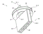
图5示出根据本发明的用于图1的光学测量设备的偏转镜装置的示例性实施例的透视图。
图6示出根据本发明的根据图5的偏转镜装置的示例性实施例从另一观察角度观察的又一透视图。
具体实施方式
如图1中所示,光学测量设备1包括壳体2,该壳体2包括底板5。被引入壳体中的是发送窗口7和接收窗口9,例如脉冲激光通过该发送窗口7被发射,被监测区域中的物体反射的激光通过该接收窗口被接收。
如图2至4中所示,发送器单元10、接收器单元20和偏转镜装置30布置在壳体3内部。发送器单元10包括发送器电路板12,例如光学发送器14设置在该发送器电路板12上,光学发送器配置为脉冲激光器,具有发送光学单元16。在所示示例性实施例中的发送器电路板12安装在电路承载件18上。接收器单元20包括接收器电路板22和接收光学单元26,例如配置为检测器的光学接收器24布置在接收器电路板22上,接收光学单元26配置为例如抛物面镜。
如图2至6中所示的,在所示示例性实施例中的偏转镜装置30包括发送镜单元31和接收镜单元32,发送镜单元31具有两个发送偏转镜31.1、31.2,发送偏转镜31.1、31.2沿共用的水平面布置在承载板35上,使得它们径向地间隔开,接收镜单元32具有两个接收偏转镜32.1、32.2,接收偏转镜32.1、32.2在每种情况下固定在承载件本体38的侧部上,使得它们径向地间隔开。如图2至6中进一步示出的,发送镜单元31和接收镜单元32布置在共用的可旋转轴34上,使得它们相对于彼此轴向地间隔开。
根据本发明,驱动可旋转轴34的驱动单元33基本上布置在两个发送偏转镜31.1、31.2之间的空间中。在所示示例性实施例中,驱动单元33布置在承载板35中的孔35.1中。凸缘形成在承载板35中的孔35.1的边缘处,以便简化驱动单元33的容置。驱动单元33由保持器36保持,该保持器36配置为覆盖件。在所示示例性实施例中,驱动单元33配置为步进马达。替换地,本领域技术人员已知的其他合适的马达和驱动件可用于驱动可旋转轴34。
布置在发送镜单元31和接收镜单元32之间且位于承载板之下的是编码盘37,该编码盘37被评估以确定可旋转轴34的旋转角。为了评估编码盘37,对应的换能器或传感器可布置在电路承载件18上。此外,可旋转轴34在两侧安装。在上端处,可旋转轴34安装在驱动单元33中,在下端处,可旋转轴34安装在安装件39中,所述安装件可引入到底板5中。
该光学测量设备的结果因此是以下描述的操作模式。固定的光学发送器14产生脉冲激光束,脉冲激光束经由旋转的发送镜单元31偏转,并通过发送窗口7被传播至要被监测的区域中。响应于被发射的脉冲激光束,被布置在监测区域中的物体或障碍物反射的脉冲激光束经由接收窗口9接收。被接收的激光束经由接收镜单元32偏转,并被从固定的接收光学单元26引导至固定的光学接收器24。光学接收器14的输出信号被评估,以确定激光束的飞行时间,以便确定距在监测区域中检测到的物体的距离。
本发明的基本思想还可以用在一种未示出的偏转镜装置中,其具有发送镜单元和接收镜单元,它们没有布置在共用的旋转轴上,但每一个具有专用的驱动单元。在这样的实施例中,如所示示例性实施例中的一样,用于发送镜单元的驱动单元基本上布置在两个发送偏转镜之间的空间中,两个发送偏转镜布置在共用的水平面中,使得它们相对于可旋转轴径向地间隔开。此外,用于接收镜单元的驱动单元基本上布置在两个接收偏转镜之间的空间中,两个接收偏转镜布置在共用的水平面中,使得它们相对于可旋转轴径向地间隔开。
Claims (10)
1.一种用于光学测量设备的偏转镜装置,其具有至少一个镜单元(31、32)和驱动单元(33),所述镜单元布置在可旋转轴(34)上并包括至少一个偏转镜(31.1、31.2、32.1、32.2),所述驱动单元(33)驱动可旋转轴(34),
其特征在于,
所述至少一个镜单元(31、32)包括至少两个偏转镜(31.1、31.2、32.1、32.2),所述至少两个偏转镜布置在共用的水平面中,使得它们相对于可旋转轴(34)径向地间隔开,而驱动单元(33)至少部分地布置在两个偏转镜(31.1、31.2、32.1、32.2)之间的空间中。
2.根据权利要求1所述的装置,
其特征在于,
所述至少两个偏转镜(31.1、31.2、32.1、32.2)布置在承载板(35)上,驱动单元(33)布置在承载板(35)的孔(35.1)中。
3.根据权利要求2所述的装置,
其特征在于,
凸缘形成在承载板(35)的孔(35.1)的边缘处。
4.根据权利要求1至3中任一项所述的装置,
其特征在于,
至少一个镜单元配置为具有至少两个发送偏转镜(31.1、31.2)的发送镜单元(31)和/或配置为具有至少两个接收偏转镜(32.1、32.2)的接收镜单元(32)。
5.根据权利要求4所述的装置,
其特征在于,
具有两个发送偏转镜(31.1、31.2)的发送镜单元(31)和具有两个接收偏转镜(32.1、32.2)的接收镜单元(32)布置在共用的可旋转轴(34)上,使得它们相对于彼此轴向地间隔开,所述两个发送偏转镜(31.1、31.2)布置在具有孔(35.1)的承载板(35)上以使得它们径向地间隔开,而驱动单元(33)布置在两个发送偏转镜(31.1、31.2)之间的空间中。
6.根据权利要求5所述的装置,
其特征在于,
接收偏转镜(32.1、32.2)在每种情况下固定在承载件本体(38)的侧部上,使得它们径向地间隔开。
7.根据权利要求5或6所述的装置,
其特征在于,
编码盘(37)布置在发送镜单元(31)和接收镜单元(32)之间处于承载板(35)之下,编码盘(37)是可评估的以确定可旋转轴(34)的旋转角。
8.根据权利要求1至7中任一项所述的装置,
其特征在于,
驱动单元(33)配置为步进马达。
9.根据权利要求1至8中任一项所述的装置,
其特征在于,
可旋转轴(34)在两侧安装。
10.一种光学测量设备,具有至少一个光学发送器(14),至少一个光学接收器(24)和偏转镜装置(30),所述偏转镜装置(30)具有至少一个镜单元(31、32)和驱动单元(33),所述镜单元布置在可旋转轴(34)上并包括至少一个偏转镜(31.1、31.2、32.1、32.2),所述驱动单元(33)驱动可旋转轴(34),
其特征在于,
所述偏转镜装置(30)根据权利要求1至9中任一项配置。
Applications Claiming Priority (3)
| Application Number | Priority Date | Filing Date | Title |
|---|---|---|---|
| DE102010047984A DE102010047984A1 (de) | 2010-10-08 | 2010-10-08 | Umlenkspiegelanordnung für eine optische Messvorrichtung und korrespondierende optische Messvorrichtung |
| DE102010047984.5 | 2010-10-08 | ||
| PCT/EP2011/066669 WO2012045603A1 (de) | 2010-10-08 | 2011-09-26 | Umlenkspiegelanordnung für eine optische messvorrichtung und korrespondierende optische messvorrichtung |
Publications (1)
| Publication Number | Publication Date |
|---|---|
| CN103154766A true CN103154766A (zh) | 2013-06-12 |
Family
ID=44993205
Family Applications (1)
| Application Number | Title | Priority Date | Filing Date |
|---|---|---|---|
| CN2011800484502A Pending CN103154766A (zh) | 2010-10-08 | 2011-09-26 | 用于光学测量设备的偏转镜组件和相应的光学测量设备 |
Country Status (8)
| Country | Link |
|---|---|
| US (1) | US9964758B2 (zh) |
| EP (1) | EP2625542B1 (zh) |
| JP (1) | JP5886298B2 (zh) |
| KR (1) | KR101820187B1 (zh) |
| CN (1) | CN103154766A (zh) |
| DE (1) | DE102010047984A1 (zh) |
| RU (1) | RU2564044C2 (zh) |
| WO (1) | WO2012045603A1 (zh) |
Cited By (2)
| Publication number | Priority date | Publication date | Assignee | Title |
|---|---|---|---|---|
| CN107690591A (zh) * | 2015-06-03 | 2018-02-13 | 法雷奥开关和传感器有限责任公司 | 用于保持偏转镜布置的驱动单元的保持设备,具有偏转镜布置的检测设备,和机动车辆 |
| CN108369269A (zh) * | 2015-10-06 | 2018-08-03 | 日本先锋公司 | 光控制装置、光控制方法和程序 |
Families Citing this family (45)
| Publication number | Priority date | Publication date | Assignee | Title |
|---|---|---|---|---|
| DE102012020288A1 (de) | 2012-10-17 | 2014-04-17 | Valeo Schalter Und Sensoren Gmbh | Optoelektronische Detektionseinrichtung mt reduzierter Energieaufnahme, Kraftfahrzeug und entsprechendes Verfahren |
| DE102012021830A1 (de) | 2012-11-08 | 2014-05-08 | Valeo Schalter Und Sensoren Gmbh | Optoelektronische Detektionseinrichtung mit einstellbarer Biasspannung eines Avalanche-Photodetektors für ein Kraftfahrzeug, Kraftfahrzeug und entsprechendes Verfahren |
| DE102012021831A1 (de) | 2012-11-08 | 2014-05-08 | Valeo Schalter Und Sensoren Gmbh | Abtastende optoelektronische Detektionseinrichtung mit einer Detektionsschwelle, Kraftfahrzeg und entsprechendes Verfahren |
| DE102012024488A1 (de) | 2012-12-14 | 2014-06-18 | Valeo Schalter Und Sensoren Gmbh | Transimpedanzverstärker und dessen Verwendung für eine abtastende optoelektronische Detektionseinrichtung |
| DE102013012789A1 (de) | 2013-07-31 | 2015-02-05 | Valeo Schalter Und Sensoren Gmbh | Abtastende optoelektronische Detektionseinrichtung und Kraftfahrzeug mit einer solchen Detektionseinrichtung |
| DE102013012787A1 (de) | 2013-07-31 | 2015-02-05 | Valeo Schalter Und Sensoren Gmbh | Optoelektronische Messvorrichtung für ein Kraftfahrzeug und Scansensor hierfür |
| DE102014111950A1 (de) | 2013-11-27 | 2015-05-28 | Valeo Schalter Und Sensoren Gmbh | Abstastende optoelektronische Detektionseinrichtung und Verfahren zum Betreiben einer solchen Detektionseinrichtung sowie Kraftfahrzeug mit einer solchen Detektionseinrichtung |
| DE102014110510A1 (de) | 2014-07-25 | 2016-01-28 | Valeo Schalter Und Sensoren Gmbh | Leiterplatinensatz für die Sende- und Empfangskombination einer optoelektronischen Detektionseinrichtung, Detektionseinrichtung mit einem solchen Leiterplattensatz sowie Kraftfahrzeug mit einer solchen Detektionseinrichtung |
| JP5764246B1 (ja) * | 2014-09-24 | 2015-08-19 | 株式会社日立国際電気 | 基板処理装置、ガス導入シャフト及びガス供給プレート |
| DE102014114723A1 (de) | 2014-10-10 | 2016-04-14 | Valeo Schalter Und Sensoren Gmbh | Optoelektronische Detektionseinrichtung, Verfahren zum Betrieb einer solchen Detektionseinrichtung und Kraftfahrzeug mit einer solchen Detektionseinrichtung |
| DE102014118056A1 (de) | 2014-12-08 | 2016-06-09 | Valeo Schalter Und Sensoren Gmbh | Optoelektronische Detektionseinrichtung fuer ein Kraftfahrzeug sowie Verwendung einer solchen Detektionseinrichtung |
| DE102014118974A1 (de) * | 2014-12-18 | 2016-06-23 | Valeo Schalter Und Sensoren Gmbh | Laserscanner, Umlenkspiegelanordnung hierfür sowie optisches Trennmittel für eine Umlenkspiegelanordnung |
| DE102015104961A1 (de) | 2015-03-31 | 2016-10-06 | Valeo Schalter Und Sensoren Gmbh | Kraftfahrzeug mit Objektdetektion und Objektmarkierung |
| DE102015115008A1 (de) | 2015-09-08 | 2017-03-09 | Valeo Schalter Und Sensoren Gmbh | Sender- und/oder Empfängereinheit einer optischen Messvorrichtung und optische Messvorrichtung |
| DE102015118953A1 (de) | 2015-11-05 | 2017-05-11 | Valeo Schalter Und Sensoren Gmbh | Optischer Sender einer optischen Messvorrichtung, optische Messvorrichtung, Fahrerassistenzeinrichtung und Fahrzeug |
| DE102015120399A1 (de) | 2015-11-25 | 2017-06-01 | Valeo Schalter Und Sensoren Gmbh | Antriebseinrichtung zum Antreiben wenigstens eines Spiegels eine Umlenkspiegelanordnung, optische Messvorrichtung, Fahrerassistenzsystem, Verfahren zum Betreiben einer optischen Messvorrichtung |
| DE102015120538A1 (de) | 2015-11-26 | 2017-06-01 | Valeo Schalter Und Sensoren Gmbh | Laserscanner und Kraftfahrzeug mit einem Laserscanner |
| JP6657897B2 (ja) | 2015-12-10 | 2020-03-04 | 株式会社リコー | ミラー部材の加工方法 |
| DE102016113909A1 (de) | 2016-07-28 | 2018-02-01 | Valeo Schalter Und Sensoren Gmbh | Optische Sendeeinheit für eine optische Detektionsvorrichtung und Verfahren zum Betrieb einer optischen Sendeeinheit |
| DE102016118489A1 (de) | 2016-09-29 | 2018-03-29 | Valeo Schalter Und Sensoren Gmbh | Abtastende optoelektronische Detektionseinrichtung und Verfahren zum Betrieb einer solchen |
| DE102016118485A1 (de) | 2016-09-29 | 2018-03-29 | Valeo Schalter Und Sensoren Gmbh | Abtastende optoelektronische Detektionseinrichtung und Verfahren zum Betrieb einer solchen |
| DE102017103981A1 (de) | 2017-02-27 | 2018-08-30 | Valeo Schalter Und Sensoren Gmbh | Sendesignal-Umlenkanordnung für eine optische Sendeeinrichtung einer optischen Detektionsvorrichtung eines Fahrzeugs, Sendeeinrichtung, optische Detektionsvorrichtung und Fahrerassistenzsystem |
| DE102017206912A1 (de) * | 2017-04-25 | 2018-10-25 | Robert Bosch Gmbh | Laserscanner beispielsweise für ein LIDAR-System eines Fahrerassistenzsystems |
| DE102017208047A1 (de) * | 2017-05-12 | 2018-11-15 | Robert Bosch Gmbh | LIDAR-Vorrichtung und Verfahren mit vereinfachter Detektion |
| DE102017111868A1 (de) | 2017-05-31 | 2018-12-06 | Valeo Schalter Und Sensoren Gmbh | Optische Sendeeinheit sowie Verfahren zum Betrieb einer optischen Sendeeinheit |
| DE102017005395B4 (de) | 2017-06-06 | 2019-10-10 | Blickfeld GmbH | LIDAR-Entfernungsmessung mit Scanner und FLASH-Lichtquelle |
| DE102017006321A1 (de) | 2017-07-05 | 2019-01-10 | Wabco Gmbh | LIDAR Sensor mit Bezugsebeneneinstellung |
| DE102017215671A1 (de) | 2017-09-06 | 2019-03-07 | Robert Bosch Gmbh | Scansystem und Sende- und Empfangsvorrichtung für ein Scansystem |
| DE102017126046A1 (de) | 2017-11-08 | 2019-05-09 | Valeo Schalter Und Sensoren Gmbh | Optische Sendeeinrichtung für eine optische Detektionsvorrichtung, optische Detektionsvorrichtung und Fahrerassistenzsystem mit wenigstens einer optischen Sendeeinrichtung |
| US11536845B2 (en) * | 2018-10-31 | 2022-12-27 | Waymo Llc | LIDAR systems with multi-faceted mirrors |
| SG10201911740SA (en) | 2018-12-06 | 2020-07-29 | Ensco Inc | Systems and methods for analyzing a rail |
| DE102018222426A1 (de) | 2018-12-20 | 2020-06-25 | Robert Bosch Gmbh | Koaxiales Makroscanner-System |
| DE102019200764A1 (de) | 2019-01-23 | 2020-07-23 | Robert Bosch Gmbh | Optisches System, insbesondere LiDAR-System, sowie Fahrzeug |
| DE102019101968A1 (de) | 2019-01-28 | 2020-07-30 | Valeo Schalter Und Sensoren Gmbh | Sendeeinrichtung für eine optische Messvorrichtung zur Erfassung von Objekten, Lichtsignalumlenkeinrichtung, Messvorrichtung und Verfahren zum Betreiben einer Sendeeinrichtung |
| DE102019101967A1 (de) | 2019-01-28 | 2020-07-30 | Valeo Schalter Und Sensoren Gmbh | Empfangseinrichtung für eine optische Messvorrichtung zur Erfassung von Objekten, Lichtsignalumlenkeinrichtung, Messvorrichtung und Verfahren zum Betreiben einer Empfangseinrichtung |
| JP7159983B2 (ja) * | 2019-06-11 | 2022-10-25 | 株式会社デンソー | 測距装置 |
| JP7151630B2 (ja) * | 2019-06-11 | 2022-10-12 | 株式会社デンソー | 測距装置 |
| DE102019120162A1 (de) | 2019-07-25 | 2021-01-28 | Valeo Schalter Und Sensoren Gmbh | Sendeeinrichtung für eine optische Messvorrichtung zur Erfassung von Objekten, Lichtsignalumlenkeinrichtung, Messvorrichtung und Verfahren zum Betreiben einer Messvorrichtung |
| DE102019134191A1 (de) | 2019-12-12 | 2021-06-17 | Valeo Schalter Und Sensoren Gmbh | Umlenkspiegeleinrichtung für eine optische Detektionsvorrichtung und optische Detektionsvorrichtung |
| DE102020112311B3 (de) | 2020-05-06 | 2021-05-20 | Audi Aktiengesellschaft | Kraftfahrzeug mit einem optischen Umgebungssensor und Verfahren zum Betrieb eines Kraftfahrzeugs |
| KR102656294B1 (ko) * | 2020-06-23 | 2024-04-19 | 주식회사 라이드로 | 라이다 장치 |
| DE102020130879A1 (de) | 2020-11-23 | 2022-05-25 | Valeo Schalter Und Sensoren Gmbh | Gehäuse für eine Signal-Umwandlungseinrichtung einer Selektionsvorrichtung, Detektionsvorrichtung und Fahrzeug mit wenigstens einer Detektionsvorrichtung |
| KR102634228B1 (ko) * | 2021-06-02 | 2024-02-06 | 아이탑스오토모티브 주식회사 | 스캐닝 라이다 장치 |
| KR102634233B1 (ko) * | 2021-06-02 | 2024-02-06 | 아이탑스오토모티브 주식회사 | 스캐닝 라이다 장치의 회전 검출 어셈블리 및 이를 포함하는 스캐닝 라이다 장치 |
| DE102022122258A1 (de) | 2022-09-02 | 2024-03-07 | Valeo Schalter Und Sensoren Gmbh | Aktives optisches Sensorsystem mit strukturiertem Spiegel |
Citations (7)
| Publication number | Priority date | Publication date | Assignee | Title |
|---|---|---|---|---|
| US3772464A (en) * | 1972-04-17 | 1973-11-13 | Spectrotherm Corp | Rotating polygon mirror assembly with an interior motor |
| JPS6122320A (ja) * | 1984-07-11 | 1986-01-30 | Fuji Xerox Co Ltd | レ−ザビ−ム走査装置 |
| US5559320A (en) * | 1995-05-19 | 1996-09-24 | Microscan Systems Incorporated | Mounting and balancing system for rotating polygon mirror in a bar code scanner |
| US6243187B1 (en) * | 1999-02-05 | 2001-06-05 | Hitachi Koki Co., Ltd. | Polygonal mirror device |
| US6268947B1 (en) * | 1997-12-10 | 2001-07-31 | Datalogic S.P.A. | Mirror mount for a rotor and a method of production of a mirror rotor |
| US20010012145A1 (en) * | 2000-01-19 | 2001-08-09 | Sick Ag | Optical scanning device |
| EP1760631A1 (en) * | 2005-09-05 | 2007-03-07 | Datalogic S.P.A. | Scanning device for an optical code reader |
Family Cites Families (11)
| Publication number | Priority date | Publication date | Assignee | Title |
|---|---|---|---|---|
| FR2209113B1 (zh) | 1972-10-09 | 1977-04-01 | Matra Engins | |
| US4037971A (en) * | 1975-06-30 | 1977-07-26 | International Business Machines Corporation | Inspection tool |
| JPS6150084A (ja) | 1984-08-18 | 1986-03-12 | West Electric Co Ltd | 物体検知装置 |
| JP3264109B2 (ja) | 1994-10-21 | 2002-03-11 | 三菱電機株式会社 | 障害物検知装置 |
| JP3401777B2 (ja) * | 1995-12-28 | 2003-04-28 | 日産自動車株式会社 | レーザ距離測定装置 |
| DE20023480U1 (de) * | 2000-12-14 | 2004-07-08 | Sick Ag | Optische Abtastvorrichtung |
| EP1273957A1 (de) * | 2001-07-02 | 2003-01-08 | Leuze electronic GmbH + Co. | Optoelektronische Vorrichtung |
| JP3948381B2 (ja) * | 2002-09-30 | 2007-07-25 | 石川島播磨重工業株式会社 | 直方体計測方法及び直方体計測装置 |
| EP1832866B1 (en) * | 2004-07-22 | 2013-10-30 | Bea S.A. | A door system with a door and a door sensor system for detecting a target object |
| DE102005055572B4 (de) | 2005-11-19 | 2007-08-02 | Ingenieurbüro Spies GbR (vertretungsberechtigte Gesellschafter: Hans Spies, Martin Spies, 86558 Hohenwart) | Abtastender optischer Abstandssensor |
| DE102006054489A1 (de) * | 2006-11-18 | 2008-05-21 | Leuze Electronic Gmbh & Co Kg | Barcodelesegerät |
-
2010
- 2010-10-08 DE DE102010047984A patent/DE102010047984A1/de not_active Withdrawn
-
2011
- 2011-09-26 US US13/876,488 patent/US9964758B2/en active Active
- 2011-09-26 JP JP2013532117A patent/JP5886298B2/ja active Active
- 2011-09-26 WO PCT/EP2011/066669 patent/WO2012045603A1/de active Application Filing
- 2011-09-26 RU RU2013120994/28A patent/RU2564044C2/ru active
- 2011-09-26 KR KR1020137008803A patent/KR101820187B1/ko active IP Right Grant
- 2011-09-26 CN CN2011800484502A patent/CN103154766A/zh active Pending
- 2011-09-26 EP EP11770718.2A patent/EP2625542B1/de active Active
Patent Citations (7)
| Publication number | Priority date | Publication date | Assignee | Title |
|---|---|---|---|---|
| US3772464A (en) * | 1972-04-17 | 1973-11-13 | Spectrotherm Corp | Rotating polygon mirror assembly with an interior motor |
| JPS6122320A (ja) * | 1984-07-11 | 1986-01-30 | Fuji Xerox Co Ltd | レ−ザビ−ム走査装置 |
| US5559320A (en) * | 1995-05-19 | 1996-09-24 | Microscan Systems Incorporated | Mounting and balancing system for rotating polygon mirror in a bar code scanner |
| US6268947B1 (en) * | 1997-12-10 | 2001-07-31 | Datalogic S.P.A. | Mirror mount for a rotor and a method of production of a mirror rotor |
| US6243187B1 (en) * | 1999-02-05 | 2001-06-05 | Hitachi Koki Co., Ltd. | Polygonal mirror device |
| US20010012145A1 (en) * | 2000-01-19 | 2001-08-09 | Sick Ag | Optical scanning device |
| EP1760631A1 (en) * | 2005-09-05 | 2007-03-07 | Datalogic S.P.A. | Scanning device for an optical code reader |
Cited By (4)
| Publication number | Priority date | Publication date | Assignee | Title |
|---|---|---|---|---|
| CN107690591A (zh) * | 2015-06-03 | 2018-02-13 | 法雷奥开关和传感器有限责任公司 | 用于保持偏转镜布置的驱动单元的保持设备,具有偏转镜布置的检测设备,和机动车辆 |
| CN107690591B (zh) * | 2015-06-03 | 2021-03-16 | 法雷奥开关和传感器有限责任公司 | 用于保持偏转镜布置的驱动单元的保持设备,具有偏转镜布置的检测设备,和机动车辆 |
| CN108369269A (zh) * | 2015-10-06 | 2018-08-03 | 日本先锋公司 | 光控制装置、光控制方法和程序 |
| CN108369269B (zh) * | 2015-10-06 | 2022-06-14 | 日本先锋公司 | 光控制装置、光控制方法和程序 |
Also Published As
| Publication number | Publication date |
|---|---|
| EP2625542A1 (de) | 2013-08-14 |
| US20140029075A1 (en) | 2014-01-30 |
| KR20130118864A (ko) | 2013-10-30 |
| JP2013546009A (ja) | 2013-12-26 |
| EP2625542B1 (de) | 2019-03-20 |
| US9964758B2 (en) | 2018-05-08 |
| RU2013120994A (ru) | 2014-11-20 |
| DE102010047984A1 (de) | 2012-04-12 |
| WO2012045603A1 (de) | 2012-04-12 |
| RU2564044C2 (ru) | 2015-09-27 |
| JP5886298B2 (ja) | 2016-03-16 |
| KR101820187B1 (ko) | 2018-01-18 |
Similar Documents
| Publication | Publication Date | Title |
|---|---|---|
| CN103154766A (zh) | 用于光学测量设备的偏转镜组件和相应的光学测量设备 | |
| CN108474654B (zh) | 激光测量装置和移动平台 | |
| US10261174B2 (en) | Laser radar device | |
| US20200166614A1 (en) | Laser scanner and motor vehicle comprising a laser scanner | |
| CN115461260B (zh) | 玻璃镜附接至旋转金属电机框架 | |
| KR20160111571A (ko) | 3차원 레이저 스캐닝 시스템 | |
| CN107976664B (zh) | 激光雷达传感器和用于对周围进行光学扫描的方法 | |
| CN113075680B (zh) | 激光雷达和激光雷达的制造方法 | |
| CN110346811B (zh) | 激光雷达及其探测装置 | |
| US20190011539A1 (en) | Light Projecting/Reception Unit And Radar | |
| US20140340668A1 (en) | Apparatus for measuring distance | |
| US11567213B2 (en) | Dual shaft axial flux motor for optical scanners | |
| JP5853863B2 (ja) | レーダ検査方法及びレーダ検査装置 | |
| EP2781932B1 (en) | Distance measurement apparatus | |
| CN115220064A (zh) | 激光雷达装置及其控制方法 | |
| CN109891264B (zh) | 用于机动车辆的检测装置,驾驶员辅助系统,机动车辆和方法 | |
| CN107690591B (zh) | 用于保持偏转镜布置的驱动单元的保持设备,具有偏转镜布置的检测设备,和机动车辆 | |
| CN111670341B (zh) | 驱动器、扫描模组及激光测量装置 | |
| KR20160046964A (ko) | 3차원 레이저 스캐닝 시스템 | |
| CN217467180U (zh) | 激光雷达和车辆 | |
| CN113518729A (zh) | 光学控制装置、以及包括该光学控制装置的平视显示器装置 | |
| CN114137498A (zh) | 具有扩大检测区域的激光雷达传感器 | |
| KR102260360B1 (ko) | 라이다모듈용 거치대 | |
| CN117015722A (zh) | 用于运行激光雷达系统的方法 | |
| KR20230064859A (ko) | 라이다 장치 |
Legal Events
| Date | Code | Title | Description |
|---|---|---|---|
| C06 | Publication | ||
| PB01 | Publication | ||
| C10 | Entry into substantive examination | ||
| SE01 | Entry into force of request for substantive examination | ||
| RJ01 | Rejection of invention patent application after publication |
Application publication date: 20130612 |
|
| RJ01 | Rejection of invention patent application after publication |