CN103154766A - Deflection mirror assembly for an optical measurement device and corresponding optical measurement device - Google Patents
Deflection mirror assembly for an optical measurement device and corresponding optical measurement device Download PDFInfo
- Publication number
- CN103154766A CN103154766A CN2011800484502A CN201180048450A CN103154766A CN 103154766 A CN103154766 A CN 103154766A CN 2011800484502 A CN2011800484502 A CN 2011800484502A CN 201180048450 A CN201180048450 A CN 201180048450A CN 103154766 A CN103154766 A CN 103154766A
- Authority
- CN
- China
- Prior art keywords
- mirror
- rotatable shaft
- deflecting
- driver element
- mirror unit
- Prior art date
- Legal status (The legal status is an assumption and is not a legal conclusion. Google has not performed a legal analysis and makes no representation as to the accuracy of the status listed.)
- Pending
Links
- 230000003287 optical effect Effects 0.000 title claims abstract description 41
- 238000005259 measurement Methods 0.000 title abstract 4
- 230000005540 biological transmission Effects 0.000 claims description 12
- 238000009434 installation Methods 0.000 abstract 1
- 230000004888 barrier function Effects 0.000 description 3
- 230000002349 favourable effect Effects 0.000 description 3
- 230000002146 bilateral effect Effects 0.000 description 2
- 230000001419 dependent effect Effects 0.000 description 1
- 238000001514 detection method Methods 0.000 description 1
- 238000005516 engineering process Methods 0.000 description 1
- 230000002093 peripheral effect Effects 0.000 description 1
- 238000002366 time-of-flight method Methods 0.000 description 1
Images


Classifications
-
- G—PHYSICS
- G02—OPTICS
- G02B—OPTICAL ELEMENTS, SYSTEMS OR APPARATUS
- G02B5/00—Optical elements other than lenses
- G02B5/08—Mirrors
-
- G—PHYSICS
- G02—OPTICS
- G02B—OPTICAL ELEMENTS, SYSTEMS OR APPARATUS
- G02B26/00—Optical devices or arrangements for the control of light using movable or deformable optical elements
- G02B26/08—Optical devices or arrangements for the control of light using movable or deformable optical elements for controlling the direction of light
- G02B26/10—Scanning systems
- G02B26/105—Scanning systems with one or more pivoting mirrors or galvano-mirrors
-
- G—PHYSICS
- G01—MEASURING; TESTING
- G01S—RADIO DIRECTION-FINDING; RADIO NAVIGATION; DETERMINING DISTANCE OR VELOCITY BY USE OF RADIO WAVES; LOCATING OR PRESENCE-DETECTING BY USE OF THE REFLECTION OR RERADIATION OF RADIO WAVES; ANALOGOUS ARRANGEMENTS USING OTHER WAVES
- G01S17/00—Systems using the reflection or reradiation of electromagnetic waves other than radio waves, e.g. lidar systems
- G01S17/88—Lidar systems specially adapted for specific applications
- G01S17/93—Lidar systems specially adapted for specific applications for anti-collision purposes
-
- G—PHYSICS
- G01—MEASURING; TESTING
- G01S—RADIO DIRECTION-FINDING; RADIO NAVIGATION; DETERMINING DISTANCE OR VELOCITY BY USE OF RADIO WAVES; LOCATING OR PRESENCE-DETECTING BY USE OF THE REFLECTION OR RERADIATION OF RADIO WAVES; ANALOGOUS ARRANGEMENTS USING OTHER WAVES
- G01S7/00—Details of systems according to groups G01S13/00, G01S15/00, G01S17/00
- G01S7/48—Details of systems according to groups G01S13/00, G01S15/00, G01S17/00 of systems according to group G01S17/00
- G01S7/481—Constructional features, e.g. arrangements of optical elements
- G01S7/4817—Constructional features, e.g. arrangements of optical elements relating to scanning
-
- G—PHYSICS
- G02—OPTICS
- G02B—OPTICAL ELEMENTS, SYSTEMS OR APPARATUS
- G02B26/00—Optical devices or arrangements for the control of light using movable or deformable optical elements
- G02B26/08—Optical devices or arrangements for the control of light using movable or deformable optical elements for controlling the direction of light
-
- G—PHYSICS
- G01—MEASURING; TESTING
- G01C—MEASURING DISTANCES, LEVELS OR BEARINGS; SURVEYING; NAVIGATION; GYROSCOPIC INSTRUMENTS; PHOTOGRAMMETRY OR VIDEOGRAMMETRY
- G01C3/00—Measuring distances in line of sight; Optical rangefinders
- G01C3/02—Details
- G01C3/06—Use of electric means to obtain final indication
- G01C3/08—Use of electric radiation detectors
-
- G—PHYSICS
- G01—MEASURING; TESTING
- G01S—RADIO DIRECTION-FINDING; RADIO NAVIGATION; DETERMINING DISTANCE OR VELOCITY BY USE OF RADIO WAVES; LOCATING OR PRESENCE-DETECTING BY USE OF THE REFLECTION OR RERADIATION OF RADIO WAVES; ANALOGOUS ARRANGEMENTS USING OTHER WAVES
- G01S17/00—Systems using the reflection or reradiation of electromagnetic waves other than radio waves, e.g. lidar systems
- G01S17/02—Systems using the reflection of electromagnetic waves other than radio waves
- G01S17/06—Systems determining position data of a target
- G01S17/08—Systems determining position data of a target for measuring distance only
-
- G—PHYSICS
- G01—MEASURING; TESTING
- G01S—RADIO DIRECTION-FINDING; RADIO NAVIGATION; DETERMINING DISTANCE OR VELOCITY BY USE OF RADIO WAVES; LOCATING OR PRESENCE-DETECTING BY USE OF THE REFLECTION OR RERADIATION OF RADIO WAVES; ANALOGOUS ARRANGEMENTS USING OTHER WAVES
- G01S17/00—Systems using the reflection or reradiation of electromagnetic waves other than radio waves, e.g. lidar systems
- G01S17/88—Lidar systems specially adapted for specific applications
- G01S17/93—Lidar systems specially adapted for specific applications for anti-collision purposes
- G01S17/931—Lidar systems specially adapted for specific applications for anti-collision purposes of land vehicles
-
- G—PHYSICS
- G01—MEASURING; TESTING
- G01S—RADIO DIRECTION-FINDING; RADIO NAVIGATION; DETERMINING DISTANCE OR VELOCITY BY USE OF RADIO WAVES; LOCATING OR PRESENCE-DETECTING BY USE OF THE REFLECTION OR RERADIATION OF RADIO WAVES; ANALOGOUS ARRANGEMENTS USING OTHER WAVES
- G01S7/00—Details of systems according to groups G01S13/00, G01S15/00, G01S17/00
- G01S7/48—Details of systems according to groups G01S13/00, G01S15/00, G01S17/00 of systems according to group G01S17/00
- G01S7/481—Constructional features, e.g. arrangements of optical elements
- G01S7/4811—Constructional features, e.g. arrangements of optical elements common to transmitter and receiver
-
- G—PHYSICS
- G02—OPTICS
- G02B—OPTICAL ELEMENTS, SYSTEMS OR APPARATUS
- G02B26/00—Optical devices or arrangements for the control of light using movable or deformable optical elements
- G02B26/08—Optical devices or arrangements for the control of light using movable or deformable optical elements for controlling the direction of light
- G02B26/0816—Optical devices or arrangements for the control of light using movable or deformable optical elements for controlling the direction of light by means of one or more reflecting elements
-
- G—PHYSICS
- G02—OPTICS
- G02B—OPTICAL ELEMENTS, SYSTEMS OR APPARATUS
- G02B26/00—Optical devices or arrangements for the control of light using movable or deformable optical elements
- G02B26/08—Optical devices or arrangements for the control of light using movable or deformable optical elements for controlling the direction of light
- G02B26/10—Scanning systems
- G02B26/12—Scanning systems using multifaceted mirrors
- G02B26/121—Mechanical drive devices for polygonal mirrors
Landscapes
- Physics & Mathematics (AREA)
- General Physics & Mathematics (AREA)
- Engineering & Computer Science (AREA)
- Optics & Photonics (AREA)
- Computer Networks & Wireless Communication (AREA)
- Radar, Positioning & Navigation (AREA)
- Remote Sensing (AREA)
- Electromagnetism (AREA)
- Optical Radar Systems And Details Thereof (AREA)
- Mounting And Adjusting Of Optical Elements (AREA)
- Mechanical Optical Scanning Systems (AREA)
- Mechanical Light Control Or Optical Switches (AREA)
Abstract
The invention relates to a deflection mirror assembly (30) for an optical measurement device, comprising at least one mirror unit (31, 32), which is arranged on a rotatable shaft (34) and comprises at least one deflection mirror (31.1, 31.2, 32.1, 32.2), and a drive unit (33), which drives the rotatable shaft (34), and to an optical measurement device comprising such a deflection mirror assembly (30). In order to allow the required installation space to be reduced, the at least one mirror unit (31, 32) comprises at least two deflection mirrors (31.1, 31.2, 32.1, 32.2), which are arranged in a common horizontal plane radial spaced from the rotatable shaft (34), wherein the drive unit (33) is arranged at least partially in the space between the two deflection mirrors (31.1, 31.2).
Description
Technical field
The present invention relates to a kind of deflection mirror devices that is used for optical measuring apparatus of the type of mentioning in the preamble of claim 1, and relate to a kind of optical measuring apparatus that has accordingly such deflection mirror devices.
Background technology
From scanning optical measuring equipment known in the state of the art, be called laser scanner, it determines that according to the light pulse pulsed-beam time-of-flight methods apart from the object that detects or the distance of barrier, this optical measuring apparatus is used for vehicle, for detection of the object in the monitored area or barrier in the monitored area.
Patent specification DE102005055572B4 has for example described a kind of scanning optical range sensor.Described range sensor comprises at least one laser instrument as optical transmitter, as at least one detecting device and the deflection unit of optical receiver, described deflection unit uses first mirror that the laser emission that produces is deflected on the scene that will measure, and uses the second mirror to be deflected into by the laser pulse that the object scattering is returned on described at least one detecting device.Here, the first and second mirrors are arranged on shared rotatable shaft, and this rotatable shaft is by drive unit drives.First mirror is arranged on the first retainer, and the second border is arranged on the second retainer, have the axial spacing with respect to first mirror, and driver element is arranged between two retainers.Described at least one laser instrument and described at least one detecting device with related electronic devices are arranged in upright mode.
Summary of the invention
The objective of the invention is to develop a kind of deflection mirror devices that is used for optical measuring apparatus of the type of mentioning in the preamble of claim 1, make and to reduce essential installing space, and purpose is to point out a kind of corresponding optical measuring apparatus.
The optical measuring apparatus of the deflection mirror devices of the feature with claim 1 according to the present invention by being used for laser scanner and the feature by having claim 10 has been realized this target.Other features that advantageously realize embodiments of the invention comprise in the dependent claims.
The advantage that the present invention realizes is because driver element is arranged in two spaces between deflecting mirror, can reduce the essential installing space for deflection mirror devices.Therefore, can reduce especially the setting height(from bottom) of deflection mirror devices.
Basic thought of the present invention is based on the realization of the mirror unit with two mirrors, and described two mirrors are arranged as in surface level relative to each other spaced apart, and driver element is arranged between described two mirrors subsequently.In addition, mirror unit being installed can more easily realize by mirror being arranged on loading plate or bearing part body in both sides.
A kind of deflection mirror devices for optical measuring apparatus according to the present invention comprises at least one mirror unit and driver element, and described mirror unit is arranged on rotatable shaft and comprises at least one deflecting mirror, described drive unit drives rotatable shaft.According to the present invention, described at least one mirror unit comprises at least two deflecting mirrors, and described deflecting mirror is arranged as apart from rotatable shaft radial spacing, and driver element is arranged in two spaces between deflecting mirror at least in part.
In a favourable configuration according to device of the present invention, described at least two deflecting mirrors are arranged on loading plate, and driver element is arranged in hole in back up pad.Thus, the bilateral that can more easily realize mirror unit is installed and can be reduced departing from rotatablely moving.In order to simplify the layout in the hole of driver element in loading plate, peripheral flange can be formed on the edge in hole.
Described at least one mirror unit can for example be configured to have at least two and send the transmission mirror unit of deflecting mirror and/or be configured to have at least two reception mirror units that receive deflecting mirror.
In other the favourable configurations according to device of the present invention, having two transmission mirror units that send deflecting mirror is arranged on shared rotatable shaft with the reception mirror units with two reception deflecting mirrors, make them relative to each other axially spaced apart, described two send deflecting mirrors and are arranged on the loading plate with hole so that they are radially spaced apart, and driver element is arranged in two spaces that send between deflecting mirror.Described two reception deflecting mirrors can be fixed on the sidepiece of bearing part body in each case, make them radially spaced apart.Thus, the bilateral that can more easily realize receiving mirror unit is installed and can be reduced and receives departing from the rotatablely moving of mirror unit.For the current rotation angle of sensing, code-wheel can be arranged in to send mirror unit and receive between mirror unit and be under loading plate, and described code-wheel can be evaluated to determine the rotation angle of rotatable shaft.
In other the favourable configurations according to device of the present invention, driver element is configured to step motor.In addition, rotatable shaft can be installed in both sides, to avoid oscillating motion and to depart from.
Can preferably be used in the optical measuring apparatus with at least one optical transmitter and at least one optical receiver according to deflection mirror devices of the present invention.
Description of drawings
Below with reference to accompanying drawing, exemplary embodiment of the present invention is explained in more detail, in the drawings:
Fig. 1 demonstrates the skeleton view according to the example embodiment of optical measuring apparatus of the present invention.
Fig. 2 demonstrates the detailed perspective view of the optical measuring apparatus of Fig. 1, and housing is not shown.
Fig. 3 demonstrates the detailed perspective view of the optical measuring apparatus of Fig. 1, and driver holder is not shown.
Fig. 4 demonstrates the detailed perspective view of the optical measuring apparatus of Fig. 1, and transmitter unit and driver element are not shown.
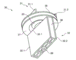
Fig. 5 illustrates the skeleton view according to the exemplary embodiment of the deflection mirror devices of the optical measuring apparatus for Fig. 1 of the present invention.
Fig. 6 illustrates the another skeleton view of observing from another viewing angle according to the exemplary embodiment of the deflection mirror devices according to Fig. 5 of the present invention.
Embodiment
As shown in fig. 1, optical measuring apparatus 1 comprises housing 2, and this housing 2 comprises base plate 5.Being introduced in housing is send window 7 and receive window 9, and for example pulse laser is launched by this send window 7, and the laser of the object reflection in the area to be monitored is received by this receive window.
As shown in Fig. 2 to 4, transmitter unit 10, acceptor unit 20 and deflection mirror devices 30 are arranged in housing 3 inside.Transmitter unit 10 comprises transmitter circuit plate 12, and for example optical transmitter 14 is arranged on this transmitter circuit plate 12, and optical transmitter is configured to pulsed laser, has the optical unit 16 of transmission.Transmitter circuit plate 12 in example shown embodiment is arranged on circuit bearing part 18.Acceptor unit 20 comprises acceptor circuit plate 22 and reception optical unit 26, and the optical receiver 24 that for example is configured to detecting device is arranged on acceptor circuit plate 22, receives optical unit 26 and is configured to for example paraboloidal mirror.
As shown in Fig. 2 to 6, deflection mirror devices 30 in example shown embodiment comprises transmission mirror unit 31 and receives mirror unit 32, send mirror unit 31 and have two transmission deflecting mirrors 31.1,31.2, sending deflecting mirror 31.1,31.2 is arranged on loading plate 35 along the surface level that shares, make them radially spaced apart, receive mirror unit 32 and have two reception deflecting mirrors 32.1,32.2, receive deflecting mirror 32.1,32.2 and be fixed in each case on the sidepiece of bearing part body 38, make them radially spaced apart.As further illustrating in Fig. 2 to 6, send mirror unit 31 and be arranged on shared rotatable shaft 34 with reception mirror unit 32, make them relative to each other axially spaced apart.
According to the present invention, the driver element 33 that drives rotatable shaft 34 is arranged in two spaces that send between deflecting mirror 31.1,31.2 basically.In example shown embodiment, driver element 33 is arranged in hole 35.1 in loading plate 35.Flange is formed on the edge in the hole 35.1 in loading plate 35, in order to simplify the accommodating of driver element 33.Driver element 33 is kept by retainer 36, and this retainer 36 is configured to covering.In example shown embodiment, driver element 33 is configured to step motor.Alternatively, other suitable motors well known by persons skilled in the art and actuator can be used for driving rotatable shaft 34.
Be arranged in that to send mirror unit 31 and receive between mirror unit 32 and be positioned under loading plate be code-wheel 37, this code-wheel 37 is evaluated to determine the rotation angle of rotatable shaft 34.In order to assess code-wheel 37, corresponding transducer or sensor can be arranged on circuit bearing part 18.In addition, rotatable shaft 34 is installed in both sides.At upper end, rotatable shaft 34 is arranged in driver element 33, and at lower end, rotatable shaft 34 is arranged in fabricated section 39, and described fabricated section can be incorporated in base plate 5.
Therefore the result of this optical measuring apparatus is operator scheme described below.Fixing optical transmitter 14 produces pulse laser beams, and pulse laser beam is via transmission mirror unit 31 deflections of rotation, and is transmitted in the zone of wanting monitored by send window 7.In response to the pulse laser beam that is launched, the pulse laser beam that is disposed in the reflection of object in the monitored area or barrier receives via receive window 9.Received laser beam is via receiving mirror unit 32 deflections, and guided to fixing optical receiver 24 from fixing reception optical unit 26.The output signal of optical receiver 14 is evaluated, to determine the flight time of laser beam, in order to determine apart from the distance of the object that detects in the monitored area.
Basic thought of the present invention can also be used in a kind of unshowned deflection mirror devices, and it has the mirror unit of transmission and receives mirror unit, and they are not arranged on shared turning axle, but each has special-purpose driver element.In such embodiments, the same in exemplary embodiment as shown, the driver element that is used for the transmission mirror unit is arranged in two spaces that send between deflecting mirror basically, and two transmission deflecting mirrors are arranged in shared surface level, make them radially spaced apart with respect to rotatable shaft.In addition, the driver element that is used for the reception mirror unit is arranged in two spaces that receive between deflecting mirror basically, and two reception deflecting mirrors are arranged in shared surface level, make them radially spaced apart with respect to rotatable shaft.
Claims (10)
1. deflection mirror devices that is used for optical measuring apparatus, it has at least one mirror unit (31,32) and driver element (33), described mirror unit is arranged in rotatable shaft (34) and goes up and comprise at least one deflecting mirror (31.1,31.2,32.1,32.2), described driver element (33) drives rotatable shaft (34)
It is characterized in that,
Described at least one mirror unit (31,32) comprises at least two deflecting mirrors (31.1,31.2,32.1,32.2), described at least two deflecting mirrors are arranged in shared surface level, make them radially spaced apart with respect to rotatable shaft (34), and driver element (33) is arranged in space between two deflecting mirrors (31.1,31.2,32.1,32.2) at least in part.
2. device according to claim 1,
It is characterized in that,
Described at least two deflecting mirrors (31.1,31.2,32.1,32.2) are arranged on loading plate (35), and driver element (33) is arranged in the hole (35.1) of loading plate (35).
3. device according to claim 2,
It is characterized in that,
Flange is formed on the edge in the hole (35.1) of loading plate (35).
4. the described device of any one according to claim 1 to 3,
It is characterized in that,
At least one mirror unit is configured to have at least two and sends the transmission mirror unit (31) of deflecting mirror (31.1,31.2) and/or be configured to have at least two reception mirror units (32) that receive deflecting mirror (32.1,32.2).
5. device according to claim 4,
It is characterized in that,
Have the transmission mirror unit (31) of two transmission deflecting mirrors (31.1,31.2) and have two reception mirror units (32) that receive deflecting mirrors (32.1,32.2) and be arranged on shared rotatable shaft (34), make them relative to each other axially spaced apart, described two send deflecting mirrors (31.1,31.2) and are arranged in and have the hole loading plate (35) of (35.1) is upper so that they are radially spaced apart, and driver element (33) is arranged in two spaces that send between deflecting mirrors (31.1,31.2).
6. device according to claim 5,
It is characterized in that,
Receive deflecting mirror (32.1,32.2) and be fixed in each case on the sidepiece of bearing part body (38), make them radially spaced apart.
7. according to claim 5 or 6 described devices,
It is characterized in that,
Code-wheel (37) is arranged in to send mirror unit (31) and receive between mirror unit (32) and is under loading plate (35), and code-wheel (37) is appreciable to determine the rotation angle of rotatable shaft (34).
8. the described device of any one according to claim 1 to 7,
It is characterized in that,
Driver element (33) is configured to step motor.
9. the described device of any one according to claim 1 to 8,
It is characterized in that,
Rotatable shaft (34) is installed in both sides.
10. optical measuring apparatus, has at least one optical transmitter (14), at least one optical receiver (24) and deflection mirror devices (30), described deflection mirror devices (30) has at least one mirror unit (31,32) and driver element (33), described mirror unit is arranged in rotatable shaft (34) and goes up and comprise at least one deflecting mirror (31.1,31.2,32.1,32.2), described driver element (33) drives rotatable shaft (34)
It is characterized in that,
Described deflection mirror devices (30) is any one configuration according to claim 1 to 9.
Applications Claiming Priority (3)
| Application Number | Priority Date | Filing Date | Title |
|---|---|---|---|
| DE102010047984A DE102010047984A1 (en) | 2010-10-08 | 2010-10-08 | Deflection mirror arrangement for an optical measuring device and corresponding optical measuring device |
| DE102010047984.5 | 2010-10-08 | ||
| PCT/EP2011/066669 WO2012045603A1 (en) | 2010-10-08 | 2011-09-26 | Deflection mirror assembly for an optical measurement device and corresponding optical measurement device |
Publications (1)
| Publication Number | Publication Date |
|---|---|
| CN103154766A true CN103154766A (en) | 2013-06-12 |
Family
ID=44993205
Family Applications (1)
| Application Number | Title | Priority Date | Filing Date |
|---|---|---|---|
| CN2011800484502A Pending CN103154766A (en) | 2010-10-08 | 2011-09-26 | Deflection mirror assembly for an optical measurement device and corresponding optical measurement device |
Country Status (8)
| Country | Link |
|---|---|
| US (1) | US9964758B2 (en) |
| EP (1) | EP2625542B1 (en) |
| JP (1) | JP5886298B2 (en) |
| KR (1) | KR101820187B1 (en) |
| CN (1) | CN103154766A (en) |
| DE (1) | DE102010047984A1 (en) |
| RU (1) | RU2564044C2 (en) |
| WO (1) | WO2012045603A1 (en) |
Cited By (3)
| Publication number | Priority date | Publication date | Assignee | Title |
|---|---|---|---|---|
| CN107690591A (en) * | 2015-06-03 | 2018-02-13 | 法雷奥开关和传感器有限责任公司 | For the holding equipment for the driver element for keeping deflecting mirror arrangement, there are the detection device that deflecting mirror is arranged, and motor vehicles |
| CN108369269A (en) * | 2015-10-06 | 2018-08-03 | 日本先锋公司 | Light control device, light control method and program |
| CN113939749A (en) * | 2019-06-11 | 2022-01-14 | 株式会社电装 | ranging device |
Families Citing this family (46)
| Publication number | Priority date | Publication date | Assignee | Title |
|---|---|---|---|---|
| DE102012020288A1 (en) | 2012-10-17 | 2014-04-17 | Valeo Schalter Und Sensoren Gmbh | Optoelectronic detection device mt reduced energy consumption, motor vehicle and corresponding method |
| DE102012021831A1 (en) | 2012-11-08 | 2014-05-08 | Valeo Schalter Und Sensoren Gmbh | Scanning opto-electronic detection device with a detection threshold, Kraftfahrzeg and corresponding method |
| DE102012021830A1 (en) | 2012-11-08 | 2014-05-08 | Valeo Schalter Und Sensoren Gmbh | Optoelectronic detection device with adjustable bias voltage of an avalanche photodetector for a motor vehicle, motor vehicle and corresponding method |
| DE102012024488A1 (en) | 2012-12-14 | 2014-06-18 | Valeo Schalter Und Sensoren Gmbh | Transimpedance amplifier and its use for a scanning optoelectronic detection device |
| DE102013012789A1 (en) | 2013-07-31 | 2015-02-05 | Valeo Schalter Und Sensoren Gmbh | Scanning optoelectronic detection device and motor vehicle with such a detection device |
| DE102013012787A1 (en) | 2013-07-31 | 2015-02-05 | Valeo Schalter Und Sensoren Gmbh | Optoelectronic measuring device for a motor vehicle and scan sensor therefor |
| DE102014111950A1 (en) | 2013-11-27 | 2015-05-28 | Valeo Schalter Und Sensoren Gmbh | Scanning opto-electronic detection device and method for operating such a detection device and motor vehicle with such a detection device |
| DE102014110510A1 (en) | 2014-07-25 | 2016-01-28 | Valeo Schalter Und Sensoren Gmbh | Circuit board set for the transmitting and receiving combination of an optoelectronic detection device, detection device with such a circuit board set and motor vehicle with such a detection device |
| JP5764246B1 (en) * | 2014-09-24 | 2015-08-19 | 株式会社日立国際電気 | Substrate processing apparatus, gas introduction shaft and gas supply plate |
| DE102014114723A1 (en) | 2014-10-10 | 2016-04-14 | Valeo Schalter Und Sensoren Gmbh | Optoelectronic detection device, method for operating such a detection device and motor vehicle with such a detection device |
| DE102014118056A1 (en) | 2014-12-08 | 2016-06-09 | Valeo Schalter Und Sensoren Gmbh | Optoelectronic detection device for a motor vehicle and use of such a detection device |
| DE102014118974A1 (en) * | 2014-12-18 | 2016-06-23 | Valeo Schalter Und Sensoren Gmbh | Laser scanner, Umlenkspiegelanordnung this and optical release means for a Umlenkspiegelanordnung |
| DE102015104961A1 (en) | 2015-03-31 | 2016-10-06 | Valeo Schalter Und Sensoren Gmbh | Motor vehicle with object detection and object marking |
| DE102015115008A1 (en) | 2015-09-08 | 2017-03-09 | Valeo Schalter Und Sensoren Gmbh | Transmitter and / or receiver unit of an optical measuring device and optical measuring device |
| DE102015118953A1 (en) | 2015-11-05 | 2017-05-11 | Valeo Schalter Und Sensoren Gmbh | Optical transmitter of an optical measuring device, optical measuring device, driver assistance device and vehicle |
| DE102015120399A1 (en) | 2015-11-25 | 2017-06-01 | Valeo Schalter Und Sensoren Gmbh | Drive device for driving at least one mirror, a deflection mirror assembly, optical measuring device, driver assistance system, method for operating an optical measuring device |
| DE102015120538A1 (en) | 2015-11-26 | 2017-06-01 | Valeo Schalter Und Sensoren Gmbh | Laser scanner and motor vehicle with a laser scanner |
| JP6657897B2 (en) | 2015-12-10 | 2020-03-04 | 株式会社リコー | Mirror member processing method |
| DE102016113909A1 (en) | 2016-07-28 | 2018-02-01 | Valeo Schalter Und Sensoren Gmbh | Optical transmission unit for an optical detection device and method for operating an optical transmission unit |
| DE102016118489A1 (en) | 2016-09-29 | 2018-03-29 | Valeo Schalter Und Sensoren Gmbh | Scanning opto-electronic detection device and method for operating such |
| DE102016118485A1 (en) | 2016-09-29 | 2018-03-29 | Valeo Schalter Und Sensoren Gmbh | Scanning opto-electronic detection device and method for operating such |
| DE102017103981A1 (en) | 2017-02-27 | 2018-08-30 | Valeo Schalter Und Sensoren Gmbh | Transmission signal deflection arrangement for an optical transmission device of an optical detection device of a vehicle, transmission device, optical detection device and driver assistance system |
| DE102017206912A1 (en) * | 2017-04-25 | 2018-10-25 | Robert Bosch Gmbh | Laser scanner, for example, for a LIDAR system of a driver assistance system |
| DE102017208047A1 (en) | 2017-05-12 | 2018-11-15 | Robert Bosch Gmbh | LIDAR device and method with simplified detection |
| DE102017111868A1 (en) | 2017-05-31 | 2018-12-06 | Valeo Schalter Und Sensoren Gmbh | Optical transmission unit and method for operating an optical transmission unit |
| DE102017005395B4 (en) | 2017-06-06 | 2019-10-10 | Blickfeld GmbH | LIDAR distance measurement with scanner and FLASH light source |
| DE102017006321A1 (en) | 2017-07-05 | 2019-01-10 | Wabco Gmbh | LIDAR sensor with reference plane adjustment |
| DE102017215671B4 (en) | 2017-09-06 | 2025-07-17 | Robert Bosch Gmbh | Scanning system and transmitting and receiving device for a scanning system |
| DE102017126046A1 (en) | 2017-11-08 | 2019-05-09 | Valeo Schalter Und Sensoren Gmbh | Optical transmission device for an optical detection device, optical detection device and driver assistance system with at least one optical transmission device |
| JP7087415B2 (en) * | 2018-01-31 | 2022-06-21 | 株式会社デンソー | Rider device |
| US11536845B2 (en) * | 2018-10-31 | 2022-12-27 | Waymo Llc | LIDAR systems with multi-faceted mirrors |
| SG10201911740SA (en) | 2018-12-06 | 2020-07-29 | Ensco Inc | Systems and methods for analyzing a rail |
| DE102018222426A1 (en) | 2018-12-20 | 2020-06-25 | Robert Bosch Gmbh | Coaxial macro scanner system |
| DE102019200764A1 (en) | 2019-01-23 | 2020-07-23 | Robert Bosch Gmbh | Optical system, in particular LiDAR system, and vehicle |
| DE102019101968A1 (en) | 2019-01-28 | 2020-07-30 | Valeo Schalter Und Sensoren Gmbh | Transmitting device for an optical measuring device for detecting objects, light signal deflection device, measuring device and method for operating a transmitting device |
| DE102019101967A1 (en) | 2019-01-28 | 2020-07-30 | Valeo Schalter Und Sensoren Gmbh | Receiving device for an optical measuring device for detecting objects, light signal deflection device, measuring device and method for operating a receiving device |
| JP7151630B2 (en) * | 2019-06-11 | 2022-10-12 | 株式会社デンソー | rangefinder |
| DE102019120162A1 (en) | 2019-07-25 | 2021-01-28 | Valeo Schalter Und Sensoren Gmbh | Transmitting device for an optical measuring device for detecting objects, light signal deflecting device, measuring device and method for operating a measuring device |
| DE102019134191A1 (en) | 2019-12-12 | 2021-06-17 | Valeo Schalter Und Sensoren Gmbh | Deflecting mirror device for an optical detection device and optical detection device |
| DE102020112311B3 (en) | 2020-05-06 | 2021-05-20 | Audi Aktiengesellschaft | Motor vehicle with an optical environment sensor and method for operating a motor vehicle |
| KR102656294B1 (en) * | 2020-06-23 | 2024-04-19 | 주식회사 라이드로 | Lidar apparatus |
| DE102020130879A1 (en) | 2020-11-23 | 2022-05-25 | Valeo Schalter Und Sensoren Gmbh | Housing for a signal conversion device of a selection device, detection device and vehicle with at least one detection device |
| KR102575733B1 (en) | 2021-02-19 | 2023-09-08 | 현대자동차주식회사 | Apparatus and method for improving position accuracy of ridar motor |
| KR102634233B1 (en) * | 2021-06-02 | 2024-02-06 | 아이탑스오토모티브 주식회사 | Rotation detecting assembly of scanning lidar device and scanning lidar device comprising the rotation detecting assembly |
| KR102634228B1 (en) * | 2021-06-02 | 2024-02-06 | 아이탑스오토모티브 주식회사 | Scanning lidar device |
| DE102022122258A1 (en) | 2022-09-02 | 2024-03-07 | Valeo Schalter Und Sensoren Gmbh | Active optical sensor system with structured mirror |
Citations (7)
| Publication number | Priority date | Publication date | Assignee | Title |
|---|---|---|---|---|
| US3772464A (en) * | 1972-04-17 | 1973-11-13 | Spectrotherm Corp | Rotating polygon mirror assembly with an interior motor |
| JPS6122320A (en) * | 1984-07-11 | 1986-01-30 | Fuji Xerox Co Ltd | Laser beam scanning device |
| US5559320A (en) * | 1995-05-19 | 1996-09-24 | Microscan Systems Incorporated | Mounting and balancing system for rotating polygon mirror in a bar code scanner |
| US6243187B1 (en) * | 1999-02-05 | 2001-06-05 | Hitachi Koki Co., Ltd. | Polygonal mirror device |
| US6268947B1 (en) * | 1997-12-10 | 2001-07-31 | Datalogic S.P.A. | Mirror mount for a rotor and a method of production of a mirror rotor |
| US20010012145A1 (en) * | 2000-01-19 | 2001-08-09 | Sick Ag | Optical scanning device |
| EP1760631A1 (en) * | 2005-09-05 | 2007-03-07 | Datalogic S.P.A. | Scanning device for an optical code reader |
Family Cites Families (11)
| Publication number | Priority date | Publication date | Assignee | Title |
|---|---|---|---|---|
| FR2209113B1 (en) | 1972-10-09 | 1977-04-01 | Matra Engins | |
| US4037971A (en) * | 1975-06-30 | 1977-07-26 | International Business Machines Corporation | Inspection tool |
| JPS6150084A (en) | 1984-08-18 | 1986-03-12 | West Electric Co Ltd | Object detector |
| JP3264109B2 (en) * | 1994-10-21 | 2002-03-11 | 三菱電機株式会社 | Obstacle detection device |
| JP3401777B2 (en) * | 1995-12-28 | 2003-04-28 | 日産自動車株式会社 | Laser distance measuring device |
| DE20023480U1 (en) * | 2000-12-14 | 2004-07-08 | Sick Ag | Optical scanning device has light transmitter, receiver close to each other with deflection devices, transmission and reception channels optically separate near light transmitter and receiver |
| EP1273957A1 (en) * | 2001-07-02 | 2003-01-08 | Leuze electronic GmbH + Co. | Opto-electronic device |
| JP3948381B2 (en) * | 2002-09-30 | 2007-07-25 | 石川島播磨重工業株式会社 | Cuboid measurement method and cuboid measurement apparatus |
| ATE387620T1 (en) * | 2004-07-22 | 2008-03-15 | Bea Sa | LIGHT SCANNING DEVICE FOR DETECTION AROUND AUTOMATIC DOORS |
| DE102005055572B4 (en) | 2005-11-19 | 2007-08-02 | Ingenieurbüro Spies GbR (vertretungsberechtigte Gesellschafter: Hans Spies, Martin Spies, 86558 Hohenwart) | Sampling optical distance sensor |
| DE102006054489A1 (en) * | 2006-11-18 | 2008-05-21 | Leuze Electronic Gmbh & Co Kg | barcode scanner |
-
2010
- 2010-10-08 DE DE102010047984A patent/DE102010047984A1/en not_active Withdrawn
-
2011
- 2011-09-26 US US13/876,488 patent/US9964758B2/en active Active
- 2011-09-26 WO PCT/EP2011/066669 patent/WO2012045603A1/en active Application Filing
- 2011-09-26 RU RU2013120994/28A patent/RU2564044C2/en active
- 2011-09-26 EP EP11770718.2A patent/EP2625542B1/en active Active
- 2011-09-26 KR KR1020137008803A patent/KR101820187B1/en active Active
- 2011-09-26 JP JP2013532117A patent/JP5886298B2/en active Active
- 2011-09-26 CN CN2011800484502A patent/CN103154766A/en active Pending
Patent Citations (7)
| Publication number | Priority date | Publication date | Assignee | Title |
|---|---|---|---|---|
| US3772464A (en) * | 1972-04-17 | 1973-11-13 | Spectrotherm Corp | Rotating polygon mirror assembly with an interior motor |
| JPS6122320A (en) * | 1984-07-11 | 1986-01-30 | Fuji Xerox Co Ltd | Laser beam scanning device |
| US5559320A (en) * | 1995-05-19 | 1996-09-24 | Microscan Systems Incorporated | Mounting and balancing system for rotating polygon mirror in a bar code scanner |
| US6268947B1 (en) * | 1997-12-10 | 2001-07-31 | Datalogic S.P.A. | Mirror mount for a rotor and a method of production of a mirror rotor |
| US6243187B1 (en) * | 1999-02-05 | 2001-06-05 | Hitachi Koki Co., Ltd. | Polygonal mirror device |
| US20010012145A1 (en) * | 2000-01-19 | 2001-08-09 | Sick Ag | Optical scanning device |
| EP1760631A1 (en) * | 2005-09-05 | 2007-03-07 | Datalogic S.P.A. | Scanning device for an optical code reader |
Cited By (5)
| Publication number | Priority date | Publication date | Assignee | Title |
|---|---|---|---|---|
| CN107690591A (en) * | 2015-06-03 | 2018-02-13 | 法雷奥开关和传感器有限责任公司 | For the holding equipment for the driver element for keeping deflecting mirror arrangement, there are the detection device that deflecting mirror is arranged, and motor vehicles |
| CN107690591B (en) * | 2015-06-03 | 2021-03-16 | 法雷奥开关和传感器有限责任公司 | Holding device for holding a drive unit of a deflection mirror arrangement, detection device with a deflection mirror arrangement, and motor vehicle |
| CN108369269A (en) * | 2015-10-06 | 2018-08-03 | 日本先锋公司 | Light control device, light control method and program |
| CN108369269B (en) * | 2015-10-06 | 2022-06-14 | 日本先锋公司 | Light control device, light control method, and program |
| CN113939749A (en) * | 2019-06-11 | 2022-01-14 | 株式会社电装 | ranging device |
Also Published As
| Publication number | Publication date |
|---|---|
| RU2013120994A (en) | 2014-11-20 |
| DE102010047984A1 (en) | 2012-04-12 |
| US9964758B2 (en) | 2018-05-08 |
| EP2625542B1 (en) | 2019-03-20 |
| JP2013546009A (en) | 2013-12-26 |
| EP2625542A1 (en) | 2013-08-14 |
| US20140029075A1 (en) | 2014-01-30 |
| JP5886298B2 (en) | 2016-03-16 |
| RU2564044C2 (en) | 2015-09-27 |
| KR101820187B1 (en) | 2018-01-18 |
| WO2012045603A1 (en) | 2012-04-12 |
| KR20130118864A (en) | 2013-10-30 |
Similar Documents
| Publication | Publication Date | Title |
|---|---|---|
| CN103154766A (en) | Deflection mirror assembly for an optical measurement device and corresponding optical measurement device | |
| US10261174B2 (en) | Laser radar device | |
| US20200166614A1 (en) | Laser scanner and motor vehicle comprising a laser scanner | |
| CN115461260B (en) | Glass mirror attached to rotating metal motor frame | |
| KR20160111571A (en) | Three dimensional laser scanning system | |
| US11422267B1 (en) | Dual shaft axial flux motor for optical scanners | |
| CN113075680B (en) | Laser radar and method for manufacturing laser radar | |
| CN110346811B (en) | Laser radar and detection device thereof | |
| US9429652B2 (en) | Apparatus for measuring distance | |
| EP3312628B1 (en) | Light projecting and receiving device, and laser radar device provided with same | |
| JP2013245986A (en) | Radar inspection method and radar inspection device | |
| EP2781932B1 (en) | Distance measurement apparatus | |
| CN115220064B (en) | Laser radar device and control method thereof | |
| JP2005502897A (en) | Scanning device | |
| CN107690591B (en) | Holding device for holding a drive unit of a deflection mirror arrangement, detection device with a deflection mirror arrangement, and motor vehicle | |
| CN114137498A (en) | Lidar sensor with enlarged detection area | |
| CN109891264B (en) | Detection device for a motor vehicle, driver assistance system, motor vehicle and method | |
| KR20160046964A (en) | Three dimensional laser scanning system | |
| CN111670341B (en) | Driver, scanning module and laser measuring device | |
| KR102260360B1 (en) | Mounting apparatus for lidar module | |
| US20220365176A1 (en) | Systems and apparatuses for mitigating lidar noise, vibration, and harshness | |
| CN117015722A (en) | Method for operating a lidar system | |
| KR20230064859A (en) | Lidar apparatus | |
| JP2025067891A (en) | Apparatus and method for testing LiDAR sensors | |
| CN116338706A (en) | Turntable type single-line laser radar |
Legal Events
| Date | Code | Title | Description |
|---|---|---|---|
| C06 | Publication | ||
| PB01 | Publication | ||
| C10 | Entry into substantive examination | ||
| SE01 | Entry into force of request for substantive examination | ||
| RJ01 | Rejection of invention patent application after publication |
Application publication date: 20130612 |
|
| RJ01 | Rejection of invention patent application after publication |