CN101585656B - Substrate dividing apparatus and method for dividing substrate - Google Patents
Substrate dividing apparatus and method for dividing substrate Download PDFInfo
- Publication number
- CN101585656B CN101585656B CN2009101320237A CN200910132023A CN101585656B CN 101585656 B CN101585656 B CN 101585656B CN 2009101320237 A CN2009101320237 A CN 2009101320237A CN 200910132023 A CN200910132023 A CN 200910132023A CN 101585656 B CN101585656 B CN 101585656B
- Authority
- CN
- China
- Prior art keywords
- line
- cut
- substrate
- glass substrate
- female glass
- Prior art date
- Legal status (The legal status is an assumption and is not a legal conclusion. Google has not performed a legal analysis and makes no representation as to the accuracy of the status listed.)
- Expired - Fee Related
Links
Images


Classifications
-
- C—CHEMISTRY; METALLURGY
- C03—GLASS; MINERAL OR SLAG WOOL
- C03B—MANUFACTURE, SHAPING, OR SUPPLEMENTARY PROCESSES
- C03B33/00—Severing cooled glass
- C03B33/10—Glass-cutting tools, e.g. scoring tools
- C03B33/105—Details of cutting or scoring means, e.g. tips
- C03B33/107—Wheel design, e.g. materials, construction, shape
-
- B—PERFORMING OPERATIONS; TRANSPORTING
- B28—WORKING CEMENT, CLAY, OR STONE
- B28D—WORKING STONE OR STONE-LIKE MATERIALS
- B28D5/00—Fine working of gems, jewels, crystals, e.g. of semiconductor material; apparatus or devices therefor
- B28D5/0005—Fine working of gems, jewels, crystals, e.g. of semiconductor material; apparatus or devices therefor by breaking, e.g. dicing
- B28D5/0041—Fine working of gems, jewels, crystals, e.g. of semiconductor material; apparatus or devices therefor by breaking, e.g. dicing the workpiece being brought into contact with a suitably shaped rigid body which remains stationary during breaking
- B28D5/0047—Fine working of gems, jewels, crystals, e.g. of semiconductor material; apparatus or devices therefor by breaking, e.g. dicing the workpiece being brought into contact with a suitably shaped rigid body which remains stationary during breaking using fluid or gas pressure
-
- B—PERFORMING OPERATIONS; TRANSPORTING
- B28—WORKING CEMENT, CLAY, OR STONE
- B28D—WORKING STONE OR STONE-LIKE MATERIALS
- B28D5/00—Fine working of gems, jewels, crystals, e.g. of semiconductor material; apparatus or devices therefor
- B28D5/0005—Fine working of gems, jewels, crystals, e.g. of semiconductor material; apparatus or devices therefor by breaking, e.g. dicing
- B28D5/0011—Fine working of gems, jewels, crystals, e.g. of semiconductor material; apparatus or devices therefor by breaking, e.g. dicing with preliminary treatment, e.g. weakening by scoring
-
- C—CHEMISTRY; METALLURGY
- C03—GLASS; MINERAL OR SLAG WOOL
- C03B—MANUFACTURE, SHAPING, OR SUPPLEMENTARY PROCESSES
- C03B33/00—Severing cooled glass
- C03B33/02—Cutting or splitting sheet glass or ribbons; Apparatus or machines therefor
- C03B33/023—Cutting or splitting sheet glass or ribbons; Apparatus or machines therefor the sheet or ribbon being in a horizontal position
- C03B33/027—Scoring tool holders; Driving mechanisms therefor
-
- C—CHEMISTRY; METALLURGY
- C03—GLASS; MINERAL OR SLAG WOOL
- C03B—MANUFACTURE, SHAPING, OR SUPPLEMENTARY PROCESSES
- C03B33/00—Severing cooled glass
- C03B33/02—Cutting or splitting sheet glass or ribbons; Apparatus or machines therefor
- C03B33/023—Cutting or splitting sheet glass or ribbons; Apparatus or machines therefor the sheet or ribbon being in a horizontal position
- C03B33/033—Apparatus for opening score lines in glass sheets
-
- C—CHEMISTRY; METALLURGY
- C03—GLASS; MINERAL OR SLAG WOOL
- C03B—MANUFACTURE, SHAPING, OR SUPPLEMENTARY PROCESSES
- C03B33/00—Severing cooled glass
- C03B33/02—Cutting or splitting sheet glass or ribbons; Apparatus or machines therefor
- C03B33/023—Cutting or splitting sheet glass or ribbons; Apparatus or machines therefor the sheet or ribbon being in a horizontal position
- C03B33/037—Controlling or regulating
-
- C—CHEMISTRY; METALLURGY
- C03—GLASS; MINERAL OR SLAG WOOL
- C03B—MANUFACTURE, SHAPING, OR SUPPLEMENTARY PROCESSES
- C03B33/00—Severing cooled glass
- C03B33/02—Cutting or splitting sheet glass or ribbons; Apparatus or machines therefor
- C03B33/04—Cutting or splitting in curves, especially for making spectacle lenses
-
- C—CHEMISTRY; METALLURGY
- C03—GLASS; MINERAL OR SLAG WOOL
- C03B—MANUFACTURE, SHAPING, OR SUPPLEMENTARY PROCESSES
- C03B33/00—Severing cooled glass
- C03B33/07—Cutting armoured, multi-layered, coated or laminated, glass products
-
- C—CHEMISTRY; METALLURGY
- C03—GLASS; MINERAL OR SLAG WOOL
- C03B—MANUFACTURE, SHAPING, OR SUPPLEMENTARY PROCESSES
- C03B33/00—Severing cooled glass
- C03B33/09—Severing cooled glass by thermal shock
-
- C—CHEMISTRY; METALLURGY
- C03—GLASS; MINERAL OR SLAG WOOL
- C03B—MANUFACTURE, SHAPING, OR SUPPLEMENTARY PROCESSES
- C03B33/00—Severing cooled glass
- C03B33/10—Glass-cutting tools, e.g. scoring tools
-
- Y—GENERAL TAGGING OF NEW TECHNOLOGICAL DEVELOPMENTS; GENERAL TAGGING OF CROSS-SECTIONAL TECHNOLOGIES SPANNING OVER SEVERAL SECTIONS OF THE IPC; TECHNICAL SUBJECTS COVERED BY FORMER USPC CROSS-REFERENCE ART COLLECTIONS [XRACs] AND DIGESTS
- Y10—TECHNICAL SUBJECTS COVERED BY FORMER USPC
- Y10T—TECHNICAL SUBJECTS COVERED BY FORMER US CLASSIFICATION
- Y10T225/00—Severing by tearing or breaking
- Y10T225/30—Breaking or tearing apparatus
- Y10T225/304—Including means to apply thermal shock to work
-
- Y—GENERAL TAGGING OF NEW TECHNOLOGICAL DEVELOPMENTS; GENERAL TAGGING OF CROSS-SECTIONAL TECHNOLOGIES SPANNING OVER SEVERAL SECTIONS OF THE IPC; TECHNICAL SUBJECTS COVERED BY FORMER USPC CROSS-REFERENCE ART COLLECTIONS [XRACs] AND DIGESTS
- Y10—TECHNICAL SUBJECTS COVERED BY FORMER USPC
- Y10T—TECHNICAL SUBJECTS COVERED BY FORMER US CLASSIFICATION
- Y10T225/00—Severing by tearing or breaking
- Y10T225/30—Breaking or tearing apparatus
- Y10T225/307—Combined with preliminary weakener or with nonbreaking cutter
- Y10T225/321—Preliminary weakener
- Y10T225/325—With means to apply moment of force to weakened work
Landscapes
- Chemical & Material Sciences (AREA)
- Engineering & Computer Science (AREA)
- Materials Engineering (AREA)
- Organic Chemistry (AREA)
- Mechanical Engineering (AREA)
- Physics & Mathematics (AREA)
- Thermal Sciences (AREA)
- Processing Of Stones Or Stones Resemblance Materials (AREA)
- Re-Forming, After-Treatment, Cutting And Transporting Of Glass Products (AREA)
- Dicing (AREA)
Abstract
A substrate dividing apparatus for dividing a substrate comprises a scribe line forming means for forming a scribe line on a substrate and a breaking means for breaking the substrate along the scribe line. The breaking means includes a means which makes a vertical crack under the scribe line extend in the thickness direction of the substrate by spraying a heated fluid onto the scribe line formed on the substrate, which fluid has a temperature high enough to have the substrate expand.
Description
The application's dividing an application that be the denomination of invention submitted on January 28th, 2004 for the Chinese invention patent application 200480006313.2 of " substrate dividing apparatus and method for dividing substrate ".
Technical field
The present invention relates to through on substrate, forming substrate dividing apparatus that is used for cutting substrate and the method for dividing substrate that the said line of cut of line of cut (scribe line) and edge breaks off substrate.
Background technology
Liquid crystal indicator comprises having the display panel that is inserted in the liquid crystal between a pair of each other bonding glass substrate.Be included in glass substrate in the said display panel and be through female glass substrate being cut into glass substrate, glass substrate being bonded together and produced afterwards with predetermined size.
Also through thereby the female glass substrate of large size bondingly each other being formed bonding female glass substrate, afterwards each female glass substrate of bonding female glass substrate being cut into the glass substrate with predetermined size and produce described display panel.
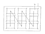
Figure 20 shows formed many lines to be rule on the traditional female glass substrate that in scribe step, uses.
Through after carrying out scribe step, carrying out break step, female glass substrate 1 is cut into four substrate 1a.
The scribe step that is used for female glass substrate 1 is; For example; Through the step of chalker with 1 line of female glass substrate, what said chalker comprised the along continuous straight runs rotation has turntable that female glass substrate 1 is mounted thereon and a line device that moves back and forth along the predeterminated level direction.
Through applying bm and carry out the break step that is used for female glass substrate 1 along being formed on line of cut on female glass substrate 1.
The details of scribe step and break step will be described below.
But female glass substrate 1 is fixed on the turntable of along continuous straight runs rotation.For example, the break bar tip vertically forms four lines of cut along line L1-L4 to be rule by particular order.Afterwards, the turntable along continuous straight runs that makes female glass substrate 1 be mounted on it revolves the angle that turn 90 degrees.Form four lines of cut along horizontal direction along line L5-L8 to be rule by particular order.Perhaps, also can form four lines of cut respectively along line L5-L8 to be rule along horizontal direction, afterwards, the turntable that makes female glass substrate 1 be mounted on it revolves the angle that turn 90 degrees, and vertically forms line of cut respectively along line L1-L4 to be rule afterwards.By this way, carry out scribe step.
Usually, form line of cut by being pressed under female glass substrate 1 lip-deep situation through rotation break bar tip in the break bar tip.Vertically crackle extends from line of cut along the thickness direction of female glass substrate 1.
On female glass substrate 1, form after the line of cut, the distortion of female glass substrate applies bm along formed line of cut on female glass substrate 1 thereby female glass substrate 1 is bent.In scribe step, make female glass substrate 1 be disconnected along line of cut through extend vertical crackle from line of cut so that vertically crackle reach with its on be formed with the surface of the relative sidepiece of the sidepiece of line of cut of female glass substrate 1.By this way, carry out break step.
After carrying out scribe step,, female glass substrate 1 is cut into four substrate 1a through carrying out break step.
Japanese Patent No.2785906 (patent documentation 1) has disclosed; As the method for from sheet glass, taking out the round-shaped glass substrate that is used for disk and CD, (scribe step) sheet glass is heated (break step) after being formed closed curve with respect to the angled line of cut of the thickness of sheet glass (line of cut).
As shown in Figure 20, the line of cut that intersects each other therein is formed in the scribble method on female glass substrate, and common female glass substrate 1 is fixed on the predetermined table.Make such as the line of cut formation device of line cutter linear mobile with respect to the female glass substrate 1 that is fixed on the platform.Therefore, after the vertical direction or horizontal direction formation line of cut of female glass substrate 1, the platform that female glass substrate is installed on it revolves the angle that turn 90 degrees.The edge forms line of cut with the vertical direction of direction on previous formation line of cut institute edge afterwards.
The applicant has researched and developed at the thickness direction along friable material substrate (the female glass substrate disclosed in Japanese Patent No.3074143) and has formed the break bar tip that has ability aspect the vertical crackle.Yet, when using a kind of like this break bar tip to carry out the intersection line, there is a kind of like this possibility, that is, can occur cracked through the place, point of crossing in the formed female glass substrate 1 of ruling along the first direction line with along second direction.
When along first direction execution line, formed vertical crackle, said vertical crackle has reached the degree of depth of the thickness that roughly is equivalent to the plate in female glass substrate 1.Therefore, when carrying out line along second direction when the break bar tip reaches near the line of cut of first direction, female glass substrate 1 sinking.Therefore, occur said cracked when the break bar tip at first direction place, point of crossing at the line of cut of first direction and second direction when line of cut moves on the glass substrate.
In the method that is used for cutting female glass substrate; Place it in the platform of the off device that is used to carry out break step; Thereby make vertical crackle put upside down the front and rear surfaces of female glass substrate through applying bm along formed line of cut simultaneously, because the competition campaign of substrate can occur cracked easily.
And; Disclosed in patent documentation 1; From sheet glass, takes out afterwards and has in the method for round-shaped glass substrate forming with respect to sheet glass angled line of cut (line of cut), need special-purpose line of cut form device (such as special use line cutter) with formation with respect to the angled line of cut of the thickness direction of glass substrate (line of cut).Because the facet with round-shaped sheet glass as the product that from sheet glass, cuts down is angled, therefore need grinding steps so that facet become for the end surfaces of Surface Vertical with round-shaped glass substrate.
Consider that the problems referred to above have made the present invention.The purpose of this invention is to provide a kind of substrate dividing apparatus and method for dividing substrate; Thereby said equipment and method can be easily along line of cut break off substrate can in substrate, not occur owing to the competition campaign of substrate cracked, and cutting substrate so that the end surfaces of substrate perpendicular to the surface of substrate.
Summary of the invention
Substrate dividing apparatus of the present invention comprises the line of cut formation device that is used on substrate, forming line of cut; And the disconnecting device that is used for breaking off substrate along said line of cut; Wherein, Said disconnecting device comprises that being used for injection temperature is enough to make the device of substrate expansible hot-fluid on formed line of cut on the substrate, thereby makes the vertical crackle that extends from line of cut further extend along the thickness direction of substrate.
Line of cut comprises first line part and the second line part at least, and first line part and the mutual intersection of second line part and each part all are straight line, curve or its combination; And when line of cut formed device and separates with substrate, line of cut formed device and forms first line partly and the second line part.
Line of cut comprises first line part and the second line part, and first line part and the mutual intersection of second line part and each part all are straight line, curve or its combination; And when line of cut formation device did not separate with substrate, line of cut formed device and forms first line part and the second line part.
Line of cut also comprises the curved portion of the end of the end that is connected in first line part glibly and second line part; The end of first line part is connected with the end of second line part; Form curved portion along the boundary line that limits the prospective region on the substrate, at least the part of boundary line be curve and at least the part of boundary line be connected in another part of boundary line glibly; And line of cut formation device forms first line part, curved portion and the second line part.
Line of cut also comprises three-way part, first curved portion and second curved portion, and first line part, second line part and three-way part are intersected each other, and each part all is straight line, curve or its combination; First line part, second line part and three-way part define the part in the 3rd zone that has polygonal shape on the substrate at least; The end of first line part is connected with the end of second line part, and another end of second line part is connected with the end of three-way part; First curved portion is the curved portion that is connected in the end and second line end partly of first line part glibly; First boundary line along limiting the first area on the substrate forms first curved portion, and at least a portion of first boundary line is a curve, and at least a portion of first boundary line is connected in the other end of first boundary line glibly; Second curved portion is the curved portion of end that is connected in the other end and the three-way part of second line part glibly; Second boundary line along limiting the second area on the substrate forms second curved portion, and at least a portion of second boundary line is a curve, and at least a portion of second boundary line is connected in another part of second boundary line glibly; First area, second area and the 3rd zone are not overlapped different zones; And line of cut formation device forms first line part, first curved portion, second line part, second curved portion and three-way part.
Line of cut also comprises three-way part, the 4th line part, first curved portion, second curved portion and the 3rd curved portion; First line part, second line part, three-way part and the 4th line part are intersected each other, and each part all is straight line, curve or its combination; First line part, second line part, three-way part and the 4th line define the 5th zone that has rectangular shape on the substrate; The end of first line part is connected with the end of second line part, and another end of second line part is connected with the end of three-way part; Another end of three-way part is connected with the end of the 4th line part; Another end of the 4th line part is connected with another end of first line part; First curved portion is the curved portion that is connected in the end and second line end partly of first line part glibly; First boundary line along limiting the first area on the substrate forms first curved portion, and at least a portion of first boundary line is a curve, and at least a portion of first boundary line is connected in the other end of first boundary line glibly; Second curved portion is the curved portion of end that is connected in the other end and the three-way part of second line part glibly; Second boundary line along limiting the second area on the substrate forms second curved portion, and at least a portion of second boundary line is a curve, and at least a portion of second boundary line is connected in another part of second boundary line glibly; The 3rd curved portion is the curved portion that is connected in the other end and the 4th line end partly of three-way part glibly; The 3rd boundary line along limiting the 3rd zone on the substrate forms the 3rd curved portion, and at least a portion of the 3rd boundary line is a curve, and at least a portion of the 3rd boundary line is connected in another part of the 3rd boundary line glibly; First area, second area, the 3rd zone and the 5th zone are the different zones of juxtaposition each other not, and line of cut forms device and forms first line part, first curved portion, second line part, second curved portion, three-way part, the 3rd curved portion and the 4th line part.
It is the line cutter with disc-like shape that line of cut forms device, and on the outer periphery surface of line cutter, is formed with the also blade on contact substrate surface that rolls.
On blade, be formed with a plurality of projections with predetermined pitch.
Said substrate dividing apparatus also comprises the heating unit that is used to heat line of cut.
When forming curved part, forms by line of cut pressure that device puts on substrate be lower than when form first line partly and second line partly at least one time form the pressure that device puts on substrate by line of cut.
Said substrate dividing apparatus also comprises the rotating driving device that is used to make the rotation of line of cut formation device upright axis.
Method for dividing substrate is included in the line of cut that forms line of cut on the substrate and forms step; And the break step of the said line of cut disconnection in edge substrate; Wherein, said break step comprises that being used for injection temperature is enough to make the device of substrate expansible hot-fluid on formed line of cut on the substrate, thereby makes the vertical crackle that extends from line of cut further extend along the thickness direction of substrate.
Line of cut comprises first line part and the second line part at least, and first line part and the mutual intersection of second line part and each part all are straight line, curve or its combination; Through being used on substrate, forming the device execution line of cut formation step of line of cut; Line of cut forms step and may further comprise the steps: form the first line part; And after forming first line part,, said device and substrate form the second line part when separating.
Line of cut comprises first line part and the second line part, and first line part and the mutual intersection of second line part and each part all are straight line, curve or its combination; Through being used on substrate, forming the device execution line of cut formation step of line of cut; Line of cut forms step and may further comprise the steps: form the first line part; And after forming first line part,, said device forms the second line part when not separating with substrate.
Line of cut also comprises the curved portion of the end of the end that is connected in first line part glibly and second line part; The end of first line part is connected with the end of second line part; Form curved portion along the boundary line that limits the prospective region on the substrate; At least the part of boundary line is a curve, and the part of boundary line is connected in the other end of boundary line glibly at least; Line of cut forms step and may further comprise the steps: form first line part, form curved portion and form the second line part.
Line of cut also comprises three-way part, first curved portion and second curved portion, and first line part, second line part and three-way part are intersected each other, and each part all is straight line, curve or its combination; First line part, second line part and three-way part define a part that has polygonal the 3rd zone on the substrate at least; The end of first line part is connected with the end of second line part, and another end of second line part is connected with the end of three-way part; First curved portion is the curved portion that is connected in the end and second line end partly of first line part glibly; First boundary line along limiting the first area on the substrate forms first curved portion, and at least a portion of first boundary line is a curve, and at least a portion of first boundary line is connected in the other end of first boundary line glibly; Second curved portion is the curved portion of end that is connected in the other end and the three-way part of second line part glibly; Second boundary line along limiting the second area on the substrate forms second curved portion, and at least a portion of second boundary line is a curve, and at least a portion of second boundary line is connected in another part of second boundary line glibly; First area, second area and the 3rd zone are not overlapped different zones; Line of cut forms step and may further comprise the steps: form first line part, form first curved portion, form second line part, form second curved portion and form three-way part.
Line of cut also comprises three-way part, the 4th line part, first curved portion, second curved portion and the 3rd curved portion; First line part, second line part, three-way part and the 4th line part are intersected each other, and each part all is straight line, curve or its combination; First line part, second line part, three-way part and the 4th line define the 5th zone that has rectangular shape on the substrate; The end of first line part is connected with the end of second line part, and another end of second line part is connected with the end of three-way part; Another end of three-way part is connected with the end of the 4th line part; Another end of the 4th line part is connected with another end of first line part; First curved portion is the curved portion that is connected in the end and second line end partly of first line part glibly; First boundary line along limiting the first area on the substrate forms first curved portion, and at least a portion of first boundary line is a curve, and at least a portion of first boundary line is connected in the other end of first boundary line glibly; Second curved portion is the curved portion of end that is connected in the other end and the three-way part of second line part glibly; Second boundary line along limiting the second area on the substrate forms second curved portion, and at least a portion of second boundary line is a curve, and at least a portion of second boundary line is connected in another part of second boundary line glibly; The 3rd curved portion is the curved portion that is connected in the other end and the 4th line end partly of three-way part glibly; The 3rd boundary line along limiting the 3rd zone on the substrate forms the 3rd curved portion, and at least a portion of the 3rd boundary line is a curve, and at least a portion of the 3rd boundary line is connected in another part of the 3rd boundary line glibly; First area, second area, the 3rd zone and the 5th zone are the different zones of juxtaposition each other not, and line of cut forms step and may further comprise the steps: form first line part, form first curved portion, form second line part, form second curved portion, form three-way part, form the 3rd curved portion and form the 4th line part.
Said method for dividing substrate also comprises the heating steps that is used to heat line of cut.
Description of drawings
Fig. 1 shows the view of the structure of the related substrate dividing apparatus of one embodiment of the invention 100.
Fig. 2 A is the front view of scribe head 20.
Fig. 2 B is the fish-eye view of scribe head 20.
Fig. 3 A is the part sectioned view of cutter fixer 27.
Fig. 3 B is the side-view of cutter fixer 27.
Fig. 4 A is the front view of line cutter 21.
Fig. 4 B is the side-view of line cutter 21.
Fig. 4 C is the enlarged view of the part (" A " part) of the line cutter 21 shown in Fig. 4 B.
Fig. 5 A is the side-view of scribe head 65.
Fig. 5 B is the front view of the major portion of scribe head 65.
Fig. 6 is to use the front view of scribe head 66 of another example of the scribe head of servomotor.
Fig. 7 shows the view that is included in the vertical crack growth device in the scribe head 20 '.
Fig. 8 shows the view of another example of vertical crack growth device.
Fig. 9 shows the schema of the related program that is used for cutting substrate of one embodiment of the invention.
Figure 10 shows the view of the related example that is arranged in the line to be rule on the employed female glass substrate of scribe step of one embodiment of the invention.
Figure 11 A shows the view of the vertical crackle that when forming line of cut through line cutter 21, occurs.
Figure 11 B shows the vertical crackle that when forming lines of cut through line cutter 51, occurred and the view of horizontal crackle.
Figure 12 shows the view of the related example that is arranged in the line to be rule on the employed female glass substrate of scribe step of another embodiment of the present invention.
Figure 13 shows the view of the related example that is arranged in the line to be rule on the employed female glass substrate of scribe step of another embodiment of the present invention.
Figure 14 shows the view of the related example that is arranged in the line to be rule on the employed female glass substrate of scribe step of another embodiment of the present invention.
Figure 15 shows the view of the related example that is arranged in the line to be rule on the employed female glass substrate of scribe step of another embodiment of the present invention.
Figure 16 shows the view that is arranged in nine substrate 1a on female glass substrate 1.
Figure 17 shows the view of the related example that is arranged in the line to be rule on the employed female glass substrate 1 of scribe step of another embodiment of the present invention.
Figure 18 shows the view of the related example that is arranged in the line to be rule on the employed female glass substrate 1 of scribe step of another embodiment of the present invention.
Figure 19 shows the view of the part that can cut the substrate dividing apparatus through bonding two formed adhesive base plate of substrate.
Figure 20 shows the view of the example that is arranged in the line to be rule on the female glass substrate of the employed tradition of scribe step.
Embodiment
Hereinafter, will describe embodiments of the invention in detail with reference to accompanying drawing.
1. substrate dividing apparatus
Fig. 1 shows the structure of the related substrate dividing apparatus of one embodiment of the invention 100.
The female glass substrate 1 of substrate dividing apparatus 100 cuttings is so that produce the glass substrate that is used for liquid crystal indicator.
The 3rd driving mechanism 47 drives scribe head CD-ROM drive motor 45 according to the control of unit 44.
Scribe head CD-ROM drive motor 45 is set on the slide unit 34.Scribe head CD-ROM drive motor 45 makes ball-screw 46 rotate.Scribe head 20 is along with the rotation of ball-screw 46 moves back and forth along tail rod 36.
Fig. 2 A shows the front of scribe head 20.Fig. 2 B shows the bottom of scribe head 20.
Head main body part 22 comprises main shaft 23 and bearing 24, and said main shaft 23 quilts are insert head main part 22 flatly.Groove part 29 is formed in the bottom of head main body part 22.Shell bearing 26 is accommodated in the groove part 29.
Shell bearing 26 is being blocked the scope internal rotation of axle 25 retardances around the axis of main shaft 23.The end parts of shell bearing 26 is connected with main shaft 23 and another end parts of shell bearing 26 contacts with retardance axle 25.Shell bearing 26 holds cutter fixer 27 so that cutter fixer 27 can be with respect to shell bearing 26 rotations.
Fig. 3 A is the part sectioned view of cutter fixer 27.Fig. 3 B is the side-view of cutter fixer 27.In Fig. 3 A and Fig. 3 B, represent by identical Reference numeral with parts identical among Fig. 2 A and Fig. 2 B.
Fig. 4 A is the front view of line cutter 21.Fig. 4 B is the side-view of line cutter 21.Fig. 4 C is the enlarged view of the part (" A " part) of the line cutter 21 shown in Fig. 4 B.
On the outer periphery surface of wheel (diameter f, thickness W) of the disc-like shape of line cutter 21, blade 21b is arranged on " V " shape outwards on the 21a of spine of outstanding blade.Blade 21b has the obtuse angle.
Spine through at blade forms groove, and a plurality of projection js outwards outstanding with predetermined pitch are formed on the blade 21b.A plurality of projection j have the size of big approximate number micron and can not be distinguished by naked eyes.
With reference to Fig. 2 A, 2B, 3A, 3B, 4A, 4B and 4C the scribe head 20 that is included in the substrate dividing apparatus 100 has been described.
The structure that is included in the scribe head in the substrate dividing apparatus 100 is not limited to the structure of scribe head 20.
Hereinafter, with the structure of describing scribe head 65.The structure of scribe head 65 is different from the structure of scribe head 20.
Fig. 5 A is the side-view of scribe head 65.Fig. 5 B is the front view of the major portion of scribe head 65.
The rotary torque of servomotor 65b is regulated in the fluctuation of the resistance that line cutter 62a received when servomotor 65b basis was rule to female glass substrate 1 at once in response to the variation in the line pressure.
This is to one among flat umbrella gear 65f turning axle of being installed to servomotor 65b and this is installed to main shaft 65d so that this is meshing with each other to flat umbrella gear 65f among the flat umbrella gear 65f another.Therefore, when servomotor when fore-and-aft direction rotates, fixer keeps assembly 65c to move up and down as pivot with main shaft 65d.Therefore, line cutter 62 move up and down with respect to the surface of female glass substrate 1.
Fig. 6 is to use the front view of scribe head 66 of another example of the scribe head of servomotor.
In Fig. 6, represent by identical Reference numeral with parts identical among Fig. 5 A and the 5B, and with the descriptions thereof are omitted.
As shown in Figure 6, the turning axle of the servomotor 65b of scribe head 66 is directly connected in fixer and keeps assembly 65c.
Hereinafter, will describe the operation of scribe head 65 and 66 in detail with reference to Fig. 5 A, 5B and 6.
When scribe head 65 and 66 drives servomotor 65b under the setting control pattern, thereby line cutter 62a moves up and down location according to this.
Through scribe head 65 and 66 line of cut is formed in the scribe step on female glass substrate 1 therein; When the position of line cutter 62a was moved away from the position in servomotor 65b, servomotor 65b produced rotary torque so that make line cutter 62a turn back to the original start position.The drive control part controls revolution moment of torsion of servomotor 65b is so that rotary torque is no more than set(ting)value.Controlled rotary torque is transferred to break bar 62a as the line pressure that is used for female glass substrate 1.That is to say that servomotor 65b applies the pressure of pushing female glass substrate 1 to line cutter 62a, and the position of vertically controlling break bar 62a.
Fig. 7 shows the view that is included in the vertical crack growth device in the scribe head 20 '.In Fig. 7, represent by identical Reference numeral with parts identical among Fig. 1 and 2 A, and with the descriptions thereof are omitted.
Scribe head 20 ' is arranged on the tail rod 36 and with acting on the disconnecting device that breaks off female glass substrate 1.
Through with vapo(u)r blasting on formed line of cut on female glass substrate 1, steam generating device 52 produces the vertical crackle that extends from line of cut along the thickness direction of female glass substrate 1.The steam that is sprayed has the temperature of female glass substrate 1 that is enough to expand.
The end of flexible pipe 52b is set to main part 52a.Another end of flexible pipe 52b is connected with injector head 52c.
In nozzle segment 52d, the vapo(u)r blasting opening is formed circle, ellipse, rectangle or shape of slit.
Fig. 8 shows the view of another example of vertical crack growth device.
As shown in Figure 8, replacing the structure (see figure 7) that the steam generation device 52 that is included in the scribe head 20 ' comprises a nozzle segment 52d, steam generating device 52 can comprise scribe head and the nozzle unit 53 that is separated with scribe head.Nozzle unit 53 comprises a plurality of nozzle segment 52d.Nozzle unit 53 is arranged on the tail rod 36.Along with tail rod 36 moves along the Y direction, steam is injected on the surface of the female glass substrate 1 that has been formed with line of cut on it.
Replace the said nozzle unit, also can be provided with and have the element that is formed on the slit on the vapo(u)r blasting opening along the Y direction shown in Fig. 8.
According to substrate dividing apparatus of the present invention, the steam with temperature of female glass substrate 1 that is enough to expand is injected on the line of cut on female glass substrate.This makes vertical crackle extend from line of cut along the thickness direction of substrate.
Because the wicking action phenomenon, be ejected into water vapour penetration on the vertical crackle with approximate number micron opening in vertical crackle.The expansion of liquids that is permeated (volumetric expansion).Therefore, vertical crack growth is to the back surface of female glass substrate 1.
And as the cutting supplementary unit, scribe head can comprise that replacing steam uses the laser oscillator of laser beam so that heat line of cut.Scribe head 20 can comprise the laser oscillator that is used for dry moisture.
Therefore, mechanically do not applying under the situation of bm along line of cut, vertically crackle can extend along the thickness direction of substrate.
Therefore, but through easily breaking off the substrate cutting substrate along line of cut so that not can owing to the competition of substrate move occur cracked.
In Fig. 1,2A, 3B and 7 example shown, line cutter 21 are as " being used on substrate, forming the line of cut formation device of line of cut ".Steam generation device is as " being used for breaking off along line of cut the disconnecting device of substrate ".Nozzle segment 52d as " be used for through heating fluid is ejected on the substrate on the formed line of cut the extension apparatus that extends from line of cut along the thickness direction of substrate of vertical crackle, heating fluid has is enough to make substrate expansible temperature ".Yet each assembly that is included in the substrate dividing apparatus of the present invention is not limited to the assembly shown in Fig. 1,2A, the 3B and 7.
As long as be included in the substrate dividing apparatus each assembly as above-mentioned " being used for forming device ", " being used for breaking off the disconnecting device of substrate " along line of cut at the line of cut that forms line of cut on the substrate, " be used for through heating fluid is ejected on the substrate on the formed line of cut the extension apparatus that extends from line of cut along the thickness direction of substrate of vertical crackle; heating fluid has is enough to make substrate expansible temperature ", each parts all can have arbitrary structures.
Above-mentioned vertical crack growth device is not limited to and uses a kind of of steam.As long as being enough to make substrate to expand, its temperature also can use heating fluid.Heating fluid for example can be steam, hot water or comprises steam and the fluid of hot water.
2. method for dividing substrate
Fig. 9 shows the schema of the related program that is used for cutting substrate of one embodiment of the invention.
Hereinafter, with the program of describing step by step with the female glass substrate 1 of substrate dividing apparatus 100 cuttings.
Program with the female glass substrate 1 of substrate dividing apparatus 100 cuttings comprises scribe step and break step.If necessary, carry out the initial setting step.
Step 501: carry out the initial setting step.The initial setting step is the step that is used for the original state of setting substrate cutting facility 100 before the beginning scribe step.The details of initial setting step will be described below.
After having accomplished the initial setting step, program advances to step 502.
Step 502: carry out scribe step.Scribe step is the step that is used on female glass substrate 1, forming line of cut.The details of scribe step will be described below.
After having accomplished scribe step, program advances to step 503.
Step 503: carry out break step.Break step is the step that is used for breaking off along line of cut female glass substrate 1.The details of break step will be described below.
After having accomplished break step, program stops.
2-1. initial setting step
The details of initial setting step (step 501) will be described hereinafter.
As the preparation work that is used for female glass substrate 1 is rule; Set the compressed-air actuated pressure of waiting to be positioned in the air cylinder that is located at head main body part 22 inside according to the various conditions that are used for female glass substrate 1 is rule (for example, the thickness of female glass substrate, material etc.).According to this setting, line cutter 21 are pushed female glass substrate 1 through predetermined load.At this moment, air cylinder contacts along the axis rotation that counterclockwise centers on main shaft 23 and with retardance axle 25 to the shell bearing 26 of its application of force.
Next, carry out and to detect step zero point.Detect in the step at zero point, detect the position on female glass substrate 1 surface.The position on female glass substrate 1 surface is to be used to make that scribe head 20 moves necessary along the direction perpendicular to female glass substrate 1.
Detect in the step at zero point, scribe head 20 moves towards the position of female glass substrate 1 surface.On the scribe head next ,/the lower device (not shown) makes the vertical direction on scribe head 20 female glass substrate 1 surface in the low speed lower edge move down.Therefore, when line cutter 21 contact with female glass substrate 1 and shell bearing 26 when being separated with retardance axle 25, on the scribe head/position of the position detecting mechanism detection scribe head 20 of lower device.Detect data and be recorded in the recording unit that is included in the unit zero point of the data that expression is detected.By this way, carry out and to detect step zero point.
When having accomplished when detecting zero point, on the scribe head/lower device makes scribe head 20 be moved upwards up to the predetermined position (for example, female glass substrate 1 surface wait position) of waiting.
In substrate dividing apparatus 100, female glass substrate 1 is arranged on the platform 31 and is fixed in platform 31.When female glass substrate is fixed in 31 last times of platform, scribe head 20 move to female glass substrate 1 surface wait the position and further move down after carry out and detect (that is the detection of female glass substrate 1 surface location) zero point.Scribe head 20 is moved upwards up to and waits the position and move along line to be rule, so that line cutter 21 are disposed near the position female glass substrate 1 end surfaces outside.In this position, the blade of line cutter 21 is moved down into the position of the upper surface 0.01mm of the female glass substrate 1 of distance to 0.2mm.
After female glass substrate 1 is arranged on the platform 31 and beginning to female glass substrate 1 before ruling during, with camera (not shown) shooting alignment mark.At least two alignment marks are set on female glass substrate 1.
According to the image of captured alignment mark, the image processing apparatus (not shown) for example produces the numerical data of relevant female glass substrate 1 information of expression.
According to the size of this numerical data, female glass substrate 1 and relevant for the data that form pattern, unit 44 calculates the position of female glass substrate 1 with respect to female glass substrate 1 end surfaces of the Y direction that begins to rule along the angle of guide rail 36 line directions with along line cutter 21.
2-2. scribe step
The details of scribe step (step 502) will be described hereinafter.
Make scribe head 20 along near the position that is preset in the outside that line to be rule on female glass substrate 1 moves to female glass substrate end surfaces.
Next, make scribe head 20 along line to be rule move and with break bar tip 21 by being pressed on female glass substrate 1 and rotation on female glass substrate 1, so that form line of cut.
Make the blade of line cutter 21 be moved down into the position of the upper surface 0.01mm of the female glass substrate 1 of distance to 0.2mm.Afterwards, unit 44 to the 3rd driving mechanism 47 output orders to drive scribe head CD-ROM drive motor 45.Response drives scribe head CD-ROM drive motor 45, and scribe head 20 moves along tail rod 36.Therefore, beginning is for the scribe step of female glass substrate 1.
Next, the view data of the alignment mark of above-mentioned image processing apparatus processing screened, and result is transported to the control section of substrate dividing apparatus.Scribe head 20 moves along guide rail 32 and 33 respectively along tail rod 36 slips and slide unit 34 and 35, so that control section is eliminated and the position deviation of arranging and being fixed on the standard fixed position of the female glass substrate 1 on the platform 31.Therefore, line cutter 21 are pressed and rotate along straight line to be rule on the predetermined Y direction.Therefore; Scribble method also is known as the line of inserting through linearity, and said method is carried out through the straight line rotation to be rule of moving along directions X at tail rod 36 and scribe head 20 makes line cutter 21 be pressed when the Y direction moves and the edge is scheduled on the Y direction.
When on directions X, carrying out line along guide rail 32 and 33, the position of female glass substrate 1 end surfaces of the directions X that unit 44 calculating line directions and edge line cutter 21 begin to rule.Make the straight line to be rule that line cutter 21 are pressed and the edge is scheduled on the directions X rotate through above-mentioned linearity insertion.
Figure 10 shows the view of the related example that is arranged in the line to be rule on the employed female glass substrate of scribe step of one embodiment of the invention.
Line to be rule is preset on female glass substrate 1, thereby an available female glass substrate 1 produces four substrates.
According to the described method for dividing substrate of the embodiment of the invention, line of cut all is formed and is able to each substrate 1a that particular order centers on four substrate 1a one by one.Break each among these four substrate 1a and from female glass substrate 1, cut four substrate 1a through the break step of after scribe step, carrying out.
For example, at first, in the upper left of the female glass substrate 1 shown in Figure 10, female glass substrate 1 is rule around substrate 1a.
In the related scribe step of the embodiment of the invention, form line of cut along straight line L9, said straight line L9 will be rule along the side that is parallel to the longitudinal direction that is used to substrate 1a to be rule.That is to say the surface that line cutter 21 edges line L9 to be rule is pressed and rotates female glass substrate 1.
In the related scribe step of the embodiment of the invention, the starting point that line cutter 21 begin to rule is the position of medial cuts on female glass substrate 1.Yet starting point can be along near the position the end surfaces outside of female glass substrate 1 of line L9 to be rule (that is the position of outside cutting).
Shown in Fig. 4 A and 4B, a plurality of projection j with predetermined pitch p are set to the spine (that is break bar tip) of the blade that centers on line cutter 21.Therefore, when line cutter 21 were pushed and rotated female glass substrate 1 surperficial, the vertical crackle that extends from line of cut can occur along the thickness direction of female glass substrate 1.Vertically crackle can roughly appear in the whole thickness of female glass substrate 1.
When forming line of cut along line L9 to be rule, tail rod 36 moves and scribe head 20 moves along the Y direction along directions X.Therefore, line cutter 21 around vertical axis with the angle of 270 degree around, the cutter 21 of therefore ruling form has the line of cut that radius is approximately the continuous curve track of 1mm (seeing the corner portions located A of Figure 10).The line that expression forms the curved portion shown in the corner portions located A of Figure 10 is through making line cutter 21 upright axis form around the angle of 270 degree.The line of expression curved portion is so formed, so that it is connected in an end of the line of cut that forms along line L9 to be rule and an end of the line of cut that forms along line L10 to be rule swimmingly.
By this way, form this curved portion along first boundary line (curve of line to be rule) of deciding the first area at ceiling substrate.At least a portion of first boundary line is a curve.At least a portion of first boundary line is connected in another part of first boundary line swimmingly.
At line cutter 21 through when moving because the pressing force that puts on female glass substrate 1 through line cutter 21 (that is, the break bar tip) is reduced, the therefore darker vertical crackle of formation in female glass substrate 1.Thickness at female glass substrate 1 is under the situation of 0.7mm, line cutter 21 through female glass substrate 1 when moving in the degree of depth of vertical crackle of formation be approximately 100 μ m to 200 μ m.
As stated, when using conventional art to carry out laterally line through the cutter 21 of ruling, the cracked line of cut that forms through ruling along first direction in female glass substrate 1 that appears at is located with the point of crossing of the line of cut that forms along the second direction line.
When along first direction formation line of cut, vertically crackle is formed in female glass substrate so that reach the degree of depth that is about as much as plate thickness.Along second direction formation line of cut the time, when line cutter 21 arrived near the line of cut of first direction, female glass substrate 1 sank.Therefore, when the break bar tip when the line of cut of first direction moves on female glass substrate, occur said cracked at the place, point of crossing of the line of cut of first direction and second direction.
In the related scribe step of embodiments of the invention, when curved portion is formed, put on pressure on female glass substrate 1 and be lower than when in line of cut that forms along line L9 to be rule and the line of cut that forms along line L10 to be rule at least one is formed and put on the pressure on female glass substrate 1 through the cutter 21 of ruling through line cutter 21.Therefore, in the related scribe step of embodiments of the invention since make line cutter 21 around, therefore put on the pressure that the contact force of female glass substrate 1 causes and be reduced.Therefore, when along first direction formation line of cut, do not form its degree of depth at the corner portions located A place of female glass substrate 1 and reach the vertical crackle that is about as much as plate thickness.Therefore, along second direction formation line of cut the time, when line cutter 21 arrived near the line of cut of first direction, female glass substrate 1 did not sink.Therefore, can avoid the cross part office in female glass substrate 1 to occur cracked.
After the angle of 270 degree, line cutter 21 move along the line L10 to be rule perpendicular to line L9 to be rule at the width of substrate 1a at the directional ring of line cutter 21.Line cutter 21 are pressed and along line L10 to be rule rotation, and line of cut is formed to such an extent that have and extend to such an extent that pass completely through the vertical crackle of thickness direction.
Afterwards; In a similar manner; Make line cutter 21 along perpendicular to the directional ring of line L10 to be rule angle around 270 degree; Form the track that radius is approximately the continuous curve of 1mm at the corner portions located B place of substrate 1a under the prerequisite that separates on the surface that makes line cutter 21 with female glass substrate 1 simultaneously, the cutter 21 of ruling afterwards are pressed and rotate along line L11 to be rule.Line cutter 21 (for example, the break bar tip) are pressed and along line L11 to be rule rotation, and line of cut is formed to such an extent that have and extend to such an extent that pass completely through the vertical crackle of thickness direction.
Afterwards; In a similar manner; Make line cutter 21 along perpendicular to the directional ring of line L11 to be rule angle around 270 degree; Form the track that radius is approximately the continuous curve of 1mm at the corner portions located C place of substrate 1a under the prerequisite that separates on the surface that makes line cutter 21 with female glass substrate 1 simultaneously, the cutter 21 of ruling afterwards are pressed and rotate along line L12 to be rule.Line cutter 21 (for example, the break bar tip) are pressed and along line L12 to be rule rotation, and line of cut is formed to such an extent that have and extend to such an extent that pass completely through the vertical crackle of thickness direction.
By this way, on female glass substrate 1, line L9 to be rule limits the zone of rectangular shape to line L12.Through carrying out the related scribe step of embodiments of the invention, the closed curve that comprises four straight cut line and four curves is formed on the periphery of substrate 1a.
As for each of other three substrates among four substrate 1a, through carrying out the related scribe step of embodiments of the invention, the closed curve that comprises four straight cut line is formed on each periphery of other three substrates among four substrate 1a.
Carried out the related scribe step of embodiments of the invention among four substrate 1a each after, can from female glass substrate 1, cut four substrate 1a through carrying out the related break step of embodiments of the invention.
In the related break step of embodiments of the invention, can be through heating or cool off each regional each of breaking off among four substrate 1a regional or except that the zone of four substrate 1a of four substrate 1a.Can carry out heating through for example well heater or the laser beam that from laser oscillator, shines to the zone.Can be through for example using cooling jet to area spray cooling media (for example, CO
2, He, N
2Deng) carry out cooling to the zone.
After in four substrate 1a of cutting from female glass substrate 1 each, use for example to comprise that the loader of vacuum absorption device takes out four substrate 1a from female glass substrate 1.The remainder of female glass substrate 1 that substrate 1a therefrom takes out is as not needing part to be dropped.
The details of break step will be described after a while.
Through carrying out the initial setting step, before carrying out scribe step, carry out the required information of scribe step (for example, about the information of the shape and size of female glass substrate 1 with about the information of line to be rule) and be set in the unit 44.According to the position of platform 31 and the position that is arranged in the female glass substrate 1 on the platform 31, scribe head CD-ROM drive motor 45 Be Controlled and linear motor 37 and 38 Be Controlled.Therefore, the line to be rule that line cutter 21 edges are set in female glass substrate 1 moves, and line of cut is formed on female glass substrate 1.
In the related scribe step of the described embodiment of the invention with reference to Figure 10, line L12 to be rule terminates on female glass substrate 1.Yet, the position that the line end position of the line L12 that the edge is to be rule can be the position on the female glass substrate 1 shown in Figure 10 or approaches female glass substrate end surfaces.And in the related scribe step of the described embodiment of the invention with reference to Figure 10, line L9-L12 to be rule is a straight line.Yet line L9-L12 to be rule is not limited to straight line.Among the line L9-L12 to be rule at least one has the combination of straight line, curve or straight line and curve.
Figure 11 A shows the vertical crackle that when forming line of cut through line cutter 21, occurs.
For example, line cutter 21 be pressed against on the glass substrate 10 that thickness is 1.1mm and the situation of rotation above that under, the blade 21b of line cutter 21 penetrates about 6 μ m from the surface of glass substrate 10.Therefore, it is less to come from the reactive force of glass substrate 10.Therefore, the vertical crackle of 0.8mm to the 1.0mm degree of depth appears having.
By this way, being formed on a plurality of projection j on the blade 21b of line cutter 21 imposes pinpoint and impacts on glass substrate 10.Therefore, when carrying out scribe step, can not occur owing to cause horizontal crackle along glass substrate 10 surperficial reactive forces.Therefore in the peripheral part of line of cut to be formed, can not occur cracked etc.
Figure 11 B shows vertical crackle and the horizontal crackle that when forming line of cut through line cutter 51, is occurred.
A plurality of projection j on the blade 21b that is formed on line cutter 21 were not formed on the blade of line cutter 51, the structure of line cutter 51 was identical with the structure of the cutter 21 of ruling.
For example, making that line cutter 51 are under the situation of rolling on the glass substrate 10 of 1.1mm at thickness, the blade of line cutter 51 penetrates about 3 μ m from the surface of glass substrate 10.Therefore, it is less to come from the reactive force of glass substrate 10.Therefore, the vertical crackle that is occurred only has the degree of depth of 0.1mm to 0.15mm.And, can produce horizontal stress along the surface of glass substrate 10.Therefore, owing to horizontal crackle appears in the surface reactive force in the horizontal direction along glass substrate 10.In the peripheral part of line of cut to be formed, occur cracked etc.
By this way, form line of cut through line cutter 21.Therefore, appearance based on horizontal stress can not occur causes on the surface of substrate 1a, producing cracked etc.
And, in the related scribe step of this embodiment of the invention and since make line cutter 21 around, therefore, the pressure that contact force caused that puts on female glass substrate 1 is reduced.When along first direction formation line of cut, do not form its degree of depth at the corner portions located A place of female glass substrate 1 and reach the vertical crackle that is about as much as plate thickness.Therefore, along second direction formation line of cut the time, when line cutter 21 arrived near the line of cut of first direction, female glass substrate 1 did not sink.Therefore, can avoid the cross part office in female glass substrate 1 to occur cracked.
And when ruling through 21 pairs of female glass substrates 1 of line cutter, the pressing force that line cutter 21 put on female glass substrate 1 can be reduced.Therefore, can limit line on the cutter 21 wearing and tearing and for the damage of line cutter 21.Therefore, line cutter 21 can stably use the long period.
Figure 12 shows related another example that is arranged in the line to be rule on the employed female glass substrate of scribe step of the embodiment of the invention.
In the related scribe step of the described embodiment of the invention with reference to Figure 12, with reference to the identical mode of the related scribe step of the described embodiment of the invention of Figure 10 along line L9 to be rule and L10 formation line of cut.
Forming along line L9 to be rule under the situation of line of cut, be positioned to the position that is close to female glass substrate 1 end surfaces outside from line cutter 21 and form line of cut along line L9 to be rule continuously.
Cracked can the influence when moving on the surface of line cutter 21 on female glass substrate 1 on female glass substrate 1 that formation line of cut section start occurs becomes the substrate of product 1a.
Make line cutter 21 along perpendicular to the directional ring of line L9 to be rule angle around 270 degree; Form the track that radius is approximately the continuous curve of 1mm at the corner portions located A place of substrate 1a simultaneously, the cutter 21 of ruling afterwards are pressed and rotate along line L12 to be rule.Line cutter 21 (for example, the break bar tip) are pressed and along line L10 to be rule rotation, and line of cut is formed to such an extent that have and extend the vertical crackle that passes completely through thickness direction.
Afterwards, after the surface of line cutter 21 and female glass substrate 1 separates, form the line L11 to be rule and the line L12 of edge and the vertical direction of line L9 to be rule by line cutter 21 along the order of line L11 to be rule and line L12 to be rule.The line L11 to be rule on the edge forms under the situation of line of cut with line L12 to be rule, and cracked can the influence when moving on the surface of line cutter 21 on female glass substrate 1 on female glass substrate 1 that formation line of cut section start occurs becomes the substrate of product 1a.
By this way, through carrying out the related scribe step of the embodiment of the invention, the closed curve that comprises four straight cut line is formed on the periphery of substrate 1a.
As for each of other three substrates among four substrate 1a, through carrying out the related scribe step of embodiments of the invention, the closed curve that comprises four straight cut line is formed on each periphery of other three substrates among four substrate 1a.
Carried out the related scribe step of embodiments of the invention among four substrate 1a each after, can from female glass substrate 1, cut each of four substrate 1a through carrying out the related break step of embodiments of the invention.
After in four substrate 1a of cutting from female glass substrate 1 each, use for example to comprise that the loader of vacuum absorption device takes out four substrate 1a from female glass substrate 1.The remainder of female glass substrate 1 that four substrate 1a therefrom take out is as not needing part not to be dropped.
In the related break step of the embodiment of the invention, can be through heating or cool off each regional each of breaking off among four substrate 1a regional or except that the zone of four substrate 1a of four substrate 1a.Can carry out heating through for example well heater or the laser beam that from laser oscillator, shines to the zone.Can be through for example using cooling jet to area spray cooling media (for example, CO
2, He, N
2Deng) carry out cooling to the zone.
The details of break step will be described after a while.
In the related scribe step of described this embodiment of the invention with reference to Figure 12 and since make line cutter 21 around, therefore, the pressure that contact force caused that puts on female glass substrate 1 is reduced.Therefore, when along first direction formation line of cut, do not form its degree of depth at the corner portions located A place of female glass substrate 1 and reach the vertical crackle that is about as much as plate thickness.Therefore, along second direction formation line of cut the time, when line cutter 21 arrived near the line of cut of first direction, female glass substrate 1 did not sink.Therefore, can avoid the cross part office in female glass substrate 1 to occur cracked.
And when ruling through 21 pairs of female glass substrates 1 of line cutter, the pressing force that line cutter 21 put on female glass substrate 1 can be reduced.Therefore, can limit line on the cutter 21 wearing and tearing and for the damage of line cutter 21.Therefore, line cutter 21 can stably use the long period.
Figure 13 shows related another example that is arranged in the line to be rule on the employed female glass substrate of scribe step of the embodiment of the invention.
In the related scribe step of described this embodiment of the invention with reference to Figure 13; At first, with formed along four lines of cut (these four lines of cut are known as main line of cut MS1 hereinafter) of line L9-L12 to be rule with reference to identical mode in the related scribe step of the described embodiment of the invention of Figure 10.After having formed main line of cut MS1, comprise the outside that four collinear time line of cut SS1 is formed on substrate 1a, being separated by with main line of cut MS1 is approximately the distance of 0.5mm-1mm.Be included in four straight cut line among the main line of cut MS1 each bar be included in time line of cut SS1 in four straight cut line in each bar all be parallel.
As described with reference to Figure 13; Be formed to such an extent that be separated by under the situation of the distance that is approximately 0.5mm-1mm at inferior line of cut SS1 with main line of cut MS1; When forming time line of cut SS1, stress is along being applied on the surface of female glass substrate perpendicular to the horizontal direction that forms the line of cut direction.Pressing force acts on the established surface portion in order to the vertical crackle that forms main line of cut MS1.In the time of on pressing force acts in order to the surface portion of the vertical crackle that forms main line of cut MS1, the directive effect that reactive force extends along the vertical width of crackle is on the bottom of vertical crackle.Therefore, vertical crackle extends along the thickness direction of female glass substrate 1.And vertically crackle arrives the back surface of female glass substrate.
Figure 14 shows related another example that is arranged in the line to be rule on the employed female glass substrate of scribe step of the embodiment of the invention.
In the related scribe step of this embodiment of the invention, during forming main line of cut MS1 and forming time line of cut SS1, line cutter 21 were once opened with female glass substrate in 1 minute.Yet, as shown in Figure 14, after forming main line of cut MS1, under the situation that not feasible line cutter 21 and female glass substrate were opened in 1 minute, form time line of cut SS1 serially.
Figure 15 shows related another example that is arranged in the line to be rule on the employed female glass substrate of scribe step of the embodiment of the invention.
With similar with reference to the related scribe step of the described embodiment of the invention of Figure 12; After the situation lower edge that makes line cutter 21 and female glass substrate open in 1 minute line L9 to be rule has formed two straight cut line with main line of cut MS1 with L10, make line cutter 21 and female glass substrate open in 1 minute.Situation lower edge line L11 and L12 to be rule not making line cutter 21 and female glass substrate open in 1 minute formed two straight cut line of residue that are included among the main line of cut MS1.To form time line of cut SS1 with the similar step of main line of cut MS1.
Figure 16 shows nine substrate 1a that are arranged on female glass substrate 1.
For example, in the sidepiece part on female glass substrate 1 longitudinal direction, line of cut is formed on each of three substrate 1a with particular order, so that form these three glass substrate 1a along the width of female glass substrate 1.
Next, on the centre portions on female glass substrate 1 longitudinal direction, line of cut is formed on each of three substrate 1a with particular order, so that form these three glass substrate 1a along the width of female glass substrate 1.
At last, in another sidepiece part on female glass substrate 1 longitudinal direction, line of cut is formed on each of three substrate 1a with particular order, so that form these three glass substrate 1a along the width of female glass substrate 1.
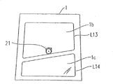
Figure 17 shows related another example that is arranged in the line to be rule on the employed female glass substrate of scribe step of the embodiment of the invention.
Figure 17 shows and is used for to be rule line L13 and the L14 of female glass substrate 1 with irregularly shaped cutting substrate 1b and 1c.
Under situation about not opening in 21 minutes with the line cutter, line cutter 21 are pressed against on female glass substrate 1 with L14 and rotate above that along having above-mentioned erose line L13 to be rule.Therefore, formation has erose line of cut on female glass substrate 1.
Above-mentioned irregularly shaped be to be different from the shape of rectangular shape and to comprise straight line and/or curve.
Figure 18 shows related another example that is arranged in the line to be rule on the employed female glass substrate of scribe step of the embodiment of the invention.
Figure 18 shows and is used for from female glass substrate 1 with the line L15 to be rule of irregularly shaped cutting substrate 1d to L18.
Every line L15-L18 to be rule is provided to such an extent that to have at least one curve of shape of erose substrate 1d corresponding with qualification.
At first, will rule cutter 21 by also rotating to form line of cut on the surface that is pressed in female glass substrate 1 above that along line L15 to be rule.Afterwards, will rule cutter 21 respectively along line L16 to be rule to L18 by also rotating to form line of cut on the surface that is pressed in female glass substrate 1 above that.
Above-mentioned irregularly shaped be to be different from the shape of rectangular shape and to comprise straight line and/or curve.
2-3. break step
The details of related break step that hereinafter, an embodiment of the present invention will be described.
For example, carry out break step for the female glass substrate that has the line of cut that forms through scribe step above that 1.
After forming line of cut along line L9 to be rule to L12, having is enough to make that the steam of female glass substrate 1 expansible temperature is injected on the formed line of cut.As shown in Figure 7, steam is ejected from the nozzle segment 52d of steam generating device 52.Through to the line of cut uperize, the vertical crackle that extends from line of cut extends at the thickness direction of female glass substrate 1.
Because the wicking action phenomenon, be ejected into water vapour penetration on the vertical crackle with approximate number micron opening in vertical crackle.The expansion of liquids that is permeated (volumetric expansion), therefore, vertically crackle extends towards the back surface of female glass substrate 1.
The nozzle unit 53 that comprises a plurality of nozzle segment 52b can be arranged on the tail rod 36 and steam can be injected into (see figure 8) on the surface of the female glass substrate 1 that has been formed with line of cut on it.
Under the situation that steam generating device 52 is not set; Can through from its on be formed with line of cut surperficial facing surfaces the female glass substrate that has been formed with line of cut on it is exerted pressure, and make female glass substrate 1 break off along the line of cut that is formed on female glass substrate.
And as the cutting supplementary unit, scribe head can comprise the laser oscillator that replaces steam use laser beam, with the heating line of cut.Scribe head 20 can comprise the laser oscillator that is used for dry moisture.
In an embodiment of the present invention, described wherein after carrying out scribe step and carried out break step such an embodiment.Yet break step only is not limited to and after carrying out scribe step, is performed.As long as having through injection is enough to make the hot-fluid that is formed with the substrate expansible temperature of line of cut on it to make the vertical crackle that extends from line of cut to extend at the thickness direction of substrate, can at random select to begin the time of scribe step and break step.For example, can carry out break step simultaneously at the formation collinear to the line of cut uperize.
Related substrate dividing apparatus and the method for dividing substrate of one embodiment of the invention described.
In an embodiment of the present invention, a female glass substrate is cut.Yet the quantity of cutting apart substrate to be cut is not limited to one.The present invention is applicable to such situation, that is, and and situation about being cut through bonding first substrate and the formed adhesive base plate of second substrate.The present invention can be cut into the for example situation of liquid display panel (the flat display board type), organic EL plate, inorganic EL plate, transmission projection machine substrate, reflective projection machine substrate etc. applicable to adhesive base plate wherein.
Figure 19 shows the view of the part that can cut the substrate dividing apparatus through bonding two formed adhesive base plate of substrate.
In an embodiment of the present invention, cutting facility and the cutting method that is used for female glass substrate described.Yet substrate to be cut is not limited to glass substrate.The present invention is applicable to for example, quartz base plate, sapphire substrate, semiconductor wafer and ceramic substrate.
And; In the related scribe step of the embodiment of the invention; At the line cutter (for example; Break bar tip 21 and 51, diamond cusp cutter, break bar or any other line form device) contact with female glass substrate 1; Periodic variation forms under the situation of line of cut the pressure of female glass substrate 1 through vibrations line cutter afterwards, and line cutter 21 obtainable effects are the same with using, and can carry out the related break step of the embodiment of the invention effectively and can obtain identical effect.
Having described wherein, four straight cut line are formed on female glass substrate with substrate cut to be an example of rectangular shape.Yet straight cut line to be formed is not limited to four.Forming under three or the more straight cut line situation with the substrate that obtains to have polygonal shape, the present invention is also applicable.Through carrying out the related scribe step of the embodiment of the invention, the closed curve that comprises three or more straight cut line and two or more curves is formed on the periphery of substrate.
Article three, every or in more straight cut line all is not limited to straight line.Or the combination of at least one the had straight line in more straight cut line, curve or straight line and curve article three.
With reference to the preferred embodiments of the present invention the present invention has been described above.Invention is not to be considered as being limited to said embodiment.Be to be appreciated that scope of the present invention only explained by claim.Should be appreciated that those of ordinary skills can realize equivalent scope based on description of the invention and known technology knowledge from the description of concrete preferred embodiment.Should also be appreciated that the full content that merges with reference to mentioned said patent, patented claim and document here.
Industrial applicibility
According to substrate dividing apparatus involved in the present invention, having through injection is enough to make the hot-fluid that is formed with the substrate expansible temperature of line of cut on it, can make the vertical crackle that extends from line of cut extend at the thickness direction of substrate.
Therefore, need not mechanically apply under the situation of bm along line of cut, vertically crackle can extend on the thickness direction of substrate.
Therefore, in the substrate of competition each other, not producing under the cracked situation, can easily break off substrate along line of cut to be cut.
Claims (4)
1. one kind is used for comprising from the substrate dividing apparatus of a plurality of cell substrates of mother substrate cutting:
Be used on mother substrate, forming the line of cut formation device of line of cut; And
Be used for breaking off the disconnecting device of mother substrate along said line of cut;
Wherein, said line of cut formation device is the line cutter with disc-like shape;
On the outer periphery surface of line cutter, be formed with and roll and the surperficial blade of contact mother substrate;
On blade, be formed with a plurality of projections with predetermined pitch; And
Said disconnecting device comprises and is used to spray steam into the device on the formed line of cut on the mother substrate; The temperature of said steam is enough to make the vertical crackle that extends from line of cut further to extend so that water vapour penetration to said vertical crackle, and expands mother substrate through the steam of infiltration along the thickness direction of mother substrate;
Said disconnecting device also comprises nozzle unit; Said nozzle unit has a plurality of nozzle segments; Said nozzle segment is used for spraying steam into when said mother substrate moves at said nozzle unit the surface of mother substrate; Wherein, said nozzle unit is arranged on said line of cut and forms device and be mounted on the tail rod on it.
2. substrate dividing apparatus as claimed in claim 1; It is characterized in that; Said substrate is two adhesive base plate that substrate bonding forms; Said line of cut forms device and comprises the chalker that is used for forming on the upper and lower surface of said adhesive base plate from the both sides of adhesive base plate line of cut, and said disconnecting device comprises and is used to spray steam into the upside of said adhesive base plate and the device on the downside.
3. one kind is used for comprising from the method for dividing substrate of a plurality of cell substrates of mother substrate cutting:
Be used on mother substrate, forming the line of cut formation step of line of cut; And
Carry out the break step that is used for breaking off mother substrate along said line of cut by disconnecting device;
Wherein, the line cutter that have a disc-like shape are used to form said line of cut;
On the outer periphery surface of line cutter, be formed with and roll and the surperficial blade of contact mother substrate;
On blade, be formed with a plurality of projections with predetermined pitch; And
Said break step comprises and is used to spray steam into the step on the formed line of cut on the mother substrate; The temperature of said steam is enough to make the vertical crackle that extends from line of cut further to extend so that water vapour penetration to said vertical crackle, and expands mother substrate through the steam of infiltration along the thickness direction of mother substrate;
Said disconnecting device also comprises nozzle unit; Said nozzle unit has a plurality of nozzle segments; Said nozzle segment is used for spraying steam into when said mother substrate moves at said nozzle unit the surface of mother substrate; Wherein, said nozzle unit is arranged on said line of cut and forms device and be mounted on the tail rod on it.
4. method for dividing substrate as claimed in claim 3; It is characterized in that; Said substrate is two adhesive base plate that substrate bonding forms; Said line of cut forms step and comprises the scribe step that forms line of cut from the both sides of adhesive base plate on the upper and lower surface of said adhesive base plate, and said break step comprises the upside that sprays steam into said adhesive base plate and the step on the downside.
Applications Claiming Priority (3)
| Application Number | Priority Date | Filing Date | Title |
|---|---|---|---|
| JP2003-021109 | 2003-01-29 | ||
| JP2003021109 | 2003-01-29 | ||
| JP2003021109 | 2003-01-29 |
Related Parent Applications (1)
| Application Number | Title | Priority Date | Filing Date |
|---|---|---|---|
| CN2004800063132A Division CN1758993B (en) | 2003-01-29 | 2004-01-28 | Substrate dividing apparatus and method for dividing substrate |
Publications (2)
| Publication Number | Publication Date |
|---|---|
| CN101585656A CN101585656A (en) | 2009-11-25 |
| CN101585656B true CN101585656B (en) | 2012-03-21 |
Family
ID=32820647
Family Applications (4)
| Application Number | Title | Priority Date | Filing Date |
|---|---|---|---|
| CN2009101320237A Expired - Fee Related CN101585656B (en) | 2003-01-29 | 2004-01-28 | Substrate dividing apparatus and method for dividing substrate |
| CN2004800063132A Expired - Fee Related CN1758993B (en) | 2003-01-29 | 2004-01-28 | Substrate dividing apparatus and method for dividing substrate |
| CN2009101320241A Expired - Fee Related CN101585655B (en) | 2003-01-29 | 2004-01-28 | Substrate dividing apparatus and method for dividing substrate |
| CN2009101320256A Expired - Fee Related CN101585657B (en) | 2003-01-29 | 2004-01-28 | Substrate dividing apparatus and method for dividing substrate |
Family Applications After (3)
| Application Number | Title | Priority Date | Filing Date |
|---|---|---|---|
| CN2004800063132A Expired - Fee Related CN1758993B (en) | 2003-01-29 | 2004-01-28 | Substrate dividing apparatus and method for dividing substrate |
| CN2009101320241A Expired - Fee Related CN101585655B (en) | 2003-01-29 | 2004-01-28 | Substrate dividing apparatus and method for dividing substrate |
| CN2009101320256A Expired - Fee Related CN101585657B (en) | 2003-01-29 | 2004-01-28 | Substrate dividing apparatus and method for dividing substrate |
Country Status (7)
| Country | Link |
|---|---|
| US (1) | US20070164072A1 (en) |
| EP (1) | EP1600270A4 (en) |
| JP (2) | JP4606325B2 (en) |
| KR (1) | KR100822322B1 (en) |
| CN (4) | CN101585656B (en) |
| TW (1) | TW200420510A (en) |
| WO (1) | WO2004067243A1 (en) |
Families Citing this family (71)
| Publication number | Priority date | Publication date | Assignee | Title |
|---|---|---|---|---|
| CN100572004C (en) * | 2004-03-15 | 2009-12-23 | 三星钻石工业株式会社 | Substrate dividing system, substrate manufacturing equipment, substrate scribing method and substrate cutting method |
| KR100628276B1 (en) * | 2004-11-05 | 2006-09-27 | 엘지.필립스 엘시디 주식회사 | scribing equipment and cutting equipment of substrate having the same and method for cutting of substrate using the same |
| JP2006206361A (en) * | 2005-01-27 | 2006-08-10 | Optrex Corp | Method and apparatus for cutting glass plate |
| KR100978259B1 (en) | 2005-06-20 | 2010-08-26 | 엘지디스플레이 주식회사 | System for cutting liquid crystal display panel and method of fabricating liquid crystal display device using thereof |
| AU2006266678A1 (en) * | 2005-07-06 | 2007-01-11 | Mitsuboshi Diamond Industrial Co., Ltd. | Brittle material scribing wheel, method for manufacturing such brittle material scribing wheel, and scribing method, scribing apparatus and scribing tool using such brittle material scribing wheel |
| JP2007069477A (en) * | 2005-09-07 | 2007-03-22 | Citizen Seimitsu Co Ltd | Scribe device and indication board manufactured by using the device |
| KR100960468B1 (en) | 2005-12-29 | 2010-05-28 | 엘지디스플레이 주식회사 | Method of cutting liquid crystal display panel and method of fabricating liquid crystal display panel using the same |
| KR100596130B1 (en) * | 2006-02-06 | 2006-07-03 | 주식회사 탑 엔지니어링 | Apparatus for cutting substrate of flat panel display |
| KR100762736B1 (en) * | 2006-04-05 | 2007-10-04 | 주식회사 탑 엔지니어링 | Apparatus for cutting substrate |
| JP5023547B2 (en) | 2006-04-28 | 2012-09-12 | 坂東機工株式会社 | Glass plate cutting method and glass plate cutting machine |
| US20080251557A1 (en) * | 2007-04-12 | 2008-10-16 | Sang-Kil Kim | Scribing unit and apparatus for scribing panel with the scribing unit, and scribing method and method for manufacutring substrate |
| JP2009064905A (en) * | 2007-09-05 | 2009-03-26 | Disco Abrasive Syst Ltd | Extension method and extension apparatus |
| DE102007045383A1 (en) * | 2007-09-22 | 2008-07-17 | Bohle Ag | Production of cutting wheels for producing notched predetermined breaking points comprises forming a toothed structure using a laser beam to partially remove the peripheral region of the wheel in a specified region |
| KR100894837B1 (en) * | 2007-10-26 | 2009-04-24 | 주식회사 에스에프에이 | Glass cutting system |
| TWI466749B (en) * | 2007-11-02 | 2015-01-01 | Mitsuboshi Diamond Ind Co Ltd | Method for Segmentation of Fragile Material Substrate |
| CN101462822B (en) * | 2007-12-21 | 2012-08-29 | 鸿富锦精密工业(深圳)有限公司 | Friable non-metal workpiece with through hole and method of processing the same |
| KR101303542B1 (en) * | 2008-02-11 | 2013-09-03 | 엘지디스플레이 주식회사 | Plat Display Panel Cutting Apparatus |
| WO2009128334A1 (en) * | 2008-04-14 | 2009-10-22 | 三星ダイヤモンド工業株式会社 | Method of machining vulnerable material substrate |
| KR100890360B1 (en) * | 2008-04-21 | 2009-03-25 | 주식회사 탑 엔지니어링 | Breaking apparatus for fragile substrate and method thereof |
| DE102008059813A1 (en) * | 2008-07-17 | 2010-01-21 | Lss Laser Scribing Systems Ag | Laser-scribing system for structuring substrates for thin-film solar modules |
| KR100953084B1 (en) * | 2008-12-23 | 2010-04-19 | 주식회사 탑 엔지니어링 | Breaking apparatus for fragile substrate and method thereof |
| JP5504631B2 (en) * | 2009-01-07 | 2014-05-28 | 三星ダイヤモンド工業株式会社 | Cutter device and cutter holder |
| JP5173885B2 (en) * | 2009-02-24 | 2013-04-03 | 三星ダイヤモンド工業株式会社 | Scribing apparatus and scribing method |
| CN101503274B (en) * | 2009-02-27 | 2011-07-27 | 山东淄博民康药业包装有限公司 | Automatic cutter for glass pipe |
| KR20100107253A (en) * | 2009-03-25 | 2010-10-05 | 삼성모바일디스플레이주식회사 | Substrate cutting appartus and method for cutting substrate using the same |
| KR101041137B1 (en) * | 2009-03-25 | 2011-06-13 | 삼성모바일디스플레이주식회사 | Substrate cutting appartus and method for cutting substrate using the same |
| KR101020682B1 (en) * | 2009-05-06 | 2011-03-11 | 세메스 주식회사 | Apparatus for breaking substrate |
| JP5609870B2 (en) * | 2009-07-03 | 2014-10-22 | 旭硝子株式会社 | Cleaving method and cleaving apparatus for brittle material substrate, and vehicle window glass obtained by the cleaving method |
| CN101992507B (en) * | 2009-08-13 | 2013-06-12 | 中芯国际集成电路制造(上海)有限公司 | Wafer cutting tool and method for cutting wafer by using same |
| US8932510B2 (en) | 2009-08-28 | 2015-01-13 | Corning Incorporated | Methods for laser cutting glass substrates |
| US8946590B2 (en) * | 2009-11-30 | 2015-02-03 | Corning Incorporated | Methods for laser scribing and separating glass substrates |
| US8720228B2 (en) * | 2010-08-31 | 2014-05-13 | Corning Incorporated | Methods of separating strengthened glass substrates |
| JP5187366B2 (en) * | 2010-08-31 | 2013-04-24 | 三星ダイヤモンド工業株式会社 | Substrate break device |
| KR20120034295A (en) * | 2010-10-01 | 2012-04-12 | 주식회사 탑 엔지니어링 | Scribing method of glass panel |
| KR101327037B1 (en) * | 2010-10-18 | 2013-11-07 | 미쓰보시 다이야몬도 고교 가부시키가이샤 | Scribe head and scribe device |
| AT510986B1 (en) * | 2011-09-12 | 2012-08-15 | Inova Lisec Technologiezentrum | METHOD AND DEVICE FOR PRODUCING EDGED INTERFACES IN FLAT GLASS |
| US20130083457A1 (en) * | 2011-09-30 | 2013-04-04 | Apple Inc. | System and method for manufacturing a display panel or other patterned device |
| JP2013079170A (en) * | 2011-10-04 | 2013-05-02 | Mitsuboshi Diamond Industrial Co Ltd | Scribing method |
| TWI455200B (en) * | 2012-01-05 | 2014-10-01 | Wecon Automation Corp | Cutting device and method |
| JP5826652B2 (en) * | 2012-01-31 | 2015-12-02 | 三星ダイヤモンド工業株式会社 | Holder unit and scribing device |
| US9938180B2 (en) | 2012-06-05 | 2018-04-10 | Corning Incorporated | Methods of cutting glass using a laser |
| US9610653B2 (en) | 2012-09-21 | 2017-04-04 | Electro Scientific Industries, Inc. | Method and apparatus for separation of workpieces and articles produced thereby |
| KR101420627B1 (en) * | 2013-04-10 | 2014-07-17 | 박명아 | cutting apparatus using heating for glass panel |
| CN103341692A (en) * | 2013-06-26 | 2013-10-09 | 京东方科技集团股份有限公司 | Method for cutting irregular figure substrate and display device |
| CN103708714B (en) * | 2013-12-27 | 2016-04-20 | 合肥京东方光电科技有限公司 | Sheet glass cutting unit and method |
| CN106232311B (en) * | 2014-03-31 | 2018-11-23 | 三星钻石工业股份有限公司 | The method for dividing of brittle material substrate |
| JP6432245B2 (en) * | 2014-09-26 | 2018-12-05 | 三星ダイヤモンド工業株式会社 | Substrate cutting method |
| CN107108322B (en) * | 2014-10-29 | 2020-01-14 | 三星钻石工业股份有限公司 | Method for dividing brittle substrate |
| CN104439717B (en) * | 2014-11-19 | 2016-03-30 | 合肥京东方光电科技有限公司 | A kind of current laser cutting device and cutting method |
| JP2016104683A (en) * | 2014-11-19 | 2016-06-09 | 坂東機工株式会社 | Splitting method of glass sheet, and splitting device therefor |
| WO2016084614A1 (en) * | 2014-11-25 | 2016-06-02 | 三星ダイヤモンド工業株式会社 | Method for severing brittle substrate |
| DE102015120569A1 (en) * | 2014-12-01 | 2016-06-02 | Schott Ag | Production of wafer-like thin glass plates with structures and separation into individual smaller thin glass plates |
| CN104697926B (en) * | 2015-03-13 | 2017-08-15 | 汕头市东方科技有限公司 | A kind of chalker for being used to detect coating for metal surfaces adhesive force |
| JP6550932B2 (en) * | 2015-06-02 | 2019-07-31 | 三星ダイヤモンド工業株式会社 | Breaker, break system and break unit |
| CN107207317B (en) * | 2015-06-10 | 2020-04-03 | 坂东机工株式会社 | Cutting of glass plate, method for positioning cut glass plate, and device therefor |
| CN105271683B (en) * | 2015-10-09 | 2018-12-28 | 昆山龙腾光电有限公司 | A kind of glass cutting method |
| CN106200098B (en) * | 2016-08-30 | 2019-12-31 | 武汉华星光电技术有限公司 | Liquid crystal display substrate cutting device and cutting method |
| CN106542727B (en) * | 2016-10-10 | 2019-03-05 | 华南理工大学 | A kind of goggle with curve surface lens embrittlement forming method that micro- grinding tip precisely induces |
| JP6355001B2 (en) * | 2017-03-29 | 2018-07-11 | 三星ダイヤモンド工業株式会社 | Substrate break device |
| CN107379292B (en) * | 2017-09-15 | 2019-07-02 | 京东方科技集团股份有限公司 | Cutting method, system and the storage medium of display panel |
| JP6911720B2 (en) * | 2017-11-14 | 2021-07-28 | 日本電気硝子株式会社 | Glass plate manufacturing method and glass plate |
| CN107942566A (en) * | 2018-01-04 | 2018-04-20 | 京东方科技集团股份有限公司 | Method for dividing substrate |
| CN110590147B (en) * | 2019-09-18 | 2022-08-02 | 彩虹(合肥)液晶玻璃有限公司 | Separation method, device, equipment and cutting equipment |
| TWI715429B (en) * | 2020-02-03 | 2021-01-01 | 晶達光電股份有限公司 | Liquid crystal panel cutting device and liquid crystal panel cutting method |
| US11372278B2 (en) | 2020-02-19 | 2022-06-28 | Litemax Electronics Inc. | Liquid crystal panel cutting device and method for cutting liquid crystal panel |
| CN111517629B (en) * | 2020-05-29 | 2022-04-19 | 昆山龙腾光电股份有限公司 | Glass cutting method |
| WO2022096064A1 (en) * | 2020-11-05 | 2022-05-12 | centrotherm international AG | Method and system for producing a substrate |
| JP7448970B2 (en) | 2021-08-02 | 2024-03-13 | 三星ダイヤモンド工業株式会社 | Board breaking device and board breaking method |
| JP7408162B2 (en) | 2021-08-17 | 2024-01-05 | 三星ダイヤモンド工業株式会社 | Board breaking device and board breaking method |
| CN114163118B (en) * | 2021-12-01 | 2023-09-01 | 成都晶华光电科技股份有限公司 | Secondary laser splitting device for cutting optical glass |
| CN115432920A (en) * | 2022-10-25 | 2022-12-06 | 深圳市益铂晶科技有限公司 | Wetting splitting method for glass laser cutting |
Citations (5)
| Publication number | Priority date | Publication date | Assignee | Title |
|---|---|---|---|---|
| GB1357116A (en) * | 1971-03-23 | 1974-06-19 | Pilkington Brothers Ltd | Cutting of glass |
| US4033490A (en) * | 1975-08-01 | 1977-07-05 | Saint-Gobain Industries | Manufacture of a window by breaking the edges of a sheet of glass along a score |
| CN1150129A (en) * | 1995-11-06 | 1997-05-21 | 三星钻石工业株式会社 | Glass cutting disc |
| US5871134A (en) * | 1994-12-27 | 1999-02-16 | Asahi Glass Company Ltd. | Method and apparatus for breaking and cutting a glass ribbon |
| US6489588B1 (en) * | 1999-11-24 | 2002-12-03 | Applied Photonics, Inc. | Method and apparatus for separating non-metallic materials |
Family Cites Families (23)
| Publication number | Priority date | Publication date | Assignee | Title |
|---|---|---|---|---|
| US1587547A (en) * | 1925-11-25 | 1926-06-08 | Pittsburgh Plate Glass Co | Apparatus for severing glass sheets |
| US3520455A (en) * | 1968-09-13 | 1970-07-14 | Carborundum Co | Method for severing ceramic bodies by localized thermal action |
| US3795502A (en) * | 1972-05-26 | 1974-03-05 | Ppg Industries Inc | Method of cutting glass |
| FR2258352B1 (en) * | 1974-01-18 | 1976-10-08 | Saint Gobain | |
| US4190184A (en) * | 1978-08-23 | 1980-02-26 | Libbey-Owens-Ford Company | Method of and apparatus for thermally cutting glass |
| US4702042A (en) * | 1984-09-27 | 1987-10-27 | Libbey-Owens-Ford Co. | Cutting strengthened glass |
| JPH02102438U (en) * | 1989-01-31 | 1990-08-15 | ||
| US5913957A (en) * | 1993-05-27 | 1999-06-22 | Pyron; Donald | Slitting chamber apparatus for baghouse filters |
| JPH08175837A (en) * | 1994-12-26 | 1996-07-09 | Asahi Glass Co Ltd | Method for dividing plate glass and device therefor |
| JP3074143B2 (en) * | 1995-11-06 | 2000-08-07 | 三星ダイヤモンド工業株式会社 | Glass cutter wheel |
| JP3095999B2 (en) * | 1996-04-15 | 2000-10-10 | 株式会社ベルデックス | Glass scribing method and apparatus |
| JP2000044265A (en) * | 1998-05-29 | 2000-02-15 | Hitachi Zosen Corp | Method for forming glass foam and slag tempered body and apparatus therefor |
| US6252197B1 (en) * | 1998-12-01 | 2001-06-26 | Accudyne Display And Semiconductor Systems, Inc. | Method and apparatus for separating non-metallic substrates utilizing a supplemental mechanical force applicator |
| JP4342039B2 (en) * | 1999-06-15 | 2009-10-14 | 三星ダイヤモンド工業株式会社 | Glass scriber and scribing method |
| JP2001176820A (en) * | 1999-12-15 | 2001-06-29 | Hitachi Cable Ltd | Method for machining substrate and machining device thereof |
| DE10013688B4 (en) * | 2000-03-21 | 2004-05-13 | Leica Microsystems Nussloch Gmbh | Use of a method for producing a cut plate made of inorganic glass |
| WO2001085387A1 (en) * | 2000-05-11 | 2001-11-15 | Ptg Precision Technology Center Limited Llc | System for cutting brittle materials |
| JP4249373B2 (en) * | 2000-05-16 | 2009-04-02 | 三星ダイヤモンド工業株式会社 | Method for cross-scribing brittle materials |
| US7131562B2 (en) * | 2001-01-17 | 2006-11-07 | Mitsuboshi Diamond Industrial Co., Ltd. | Scribing and breaking apparatus, system therefor, and scribing and breaking method |
| DE10136181B4 (en) * | 2001-07-25 | 2005-02-10 | Schott Ag | A method of breaking a cut glass piece having a wall thickness of 6mm or more |
| JP4149746B2 (en) * | 2002-06-21 | 2008-09-17 | 中村留精密工業株式会社 | Method and apparatus for scribing hard brittle plate |
| AU2003268668A1 (en) * | 2002-11-22 | 2004-06-18 | Mitsuboshi Diamond Industrial Co., Ltd. | Substrate-cutting system, substrate-producing apparatus, substrate-scribing method, and substrate-cutting method |
| JP2004217492A (en) * | 2003-01-17 | 2004-08-05 | Murakami Corp | Method of cutting out glass plate |
-
2004
- 2004-01-28 CN CN2009101320237A patent/CN101585656B/en not_active Expired - Fee Related
- 2004-01-28 CN CN2004800063132A patent/CN1758993B/en not_active Expired - Fee Related
- 2004-01-28 EP EP04705923A patent/EP1600270A4/en not_active Withdrawn
- 2004-01-28 US US10/544,070 patent/US20070164072A1/en not_active Abandoned
- 2004-01-28 CN CN2009101320241A patent/CN101585655B/en not_active Expired - Fee Related
- 2004-01-28 CN CN2009101320256A patent/CN101585657B/en not_active Expired - Fee Related
- 2004-01-28 KR KR1020057014009A patent/KR100822322B1/en active IP Right Grant
- 2004-01-28 JP JP2005504731A patent/JP4606325B2/en not_active Expired - Fee Related
- 2004-01-28 WO PCT/JP2004/000780 patent/WO2004067243A1/en active Application Filing
- 2004-01-29 TW TW93102051A patent/TW200420510A/en not_active IP Right Cessation
-
2010
- 2010-03-15 JP JP2010058526A patent/JP5328049B2/en not_active Expired - Fee Related
Patent Citations (5)
| Publication number | Priority date | Publication date | Assignee | Title |
|---|---|---|---|---|
| GB1357116A (en) * | 1971-03-23 | 1974-06-19 | Pilkington Brothers Ltd | Cutting of glass |
| US4033490A (en) * | 1975-08-01 | 1977-07-05 | Saint-Gobain Industries | Manufacture of a window by breaking the edges of a sheet of glass along a score |
| US5871134A (en) * | 1994-12-27 | 1999-02-16 | Asahi Glass Company Ltd. | Method and apparatus for breaking and cutting a glass ribbon |
| CN1150129A (en) * | 1995-11-06 | 1997-05-21 | 三星钻石工业株式会社 | Glass cutting disc |
| US6489588B1 (en) * | 1999-11-24 | 2002-12-03 | Applied Photonics, Inc. | Method and apparatus for separating non-metallic materials |
Non-Patent Citations (2)
| Title |
|---|
| JP特开平5-185270A 1993.07.27 |
| JP特开平8-175837A 1996.07.09 |
Also Published As
| Publication number | Publication date |
|---|---|
| JP4606325B2 (en) | 2011-01-05 |
| KR100822322B1 (en) | 2008-04-16 |
| JP5328049B2 (en) | 2013-10-30 |
| JPWO2004067243A1 (en) | 2006-06-01 |
| CN101585655B (en) | 2013-04-24 |
| CN101585655A (en) | 2009-11-25 |
| KR20050095912A (en) | 2005-10-04 |
| CN1758993A (en) | 2006-04-12 |
| EP1600270A1 (en) | 2005-11-30 |
| TWI342300B (en) | 2011-05-21 |
| CN101585657B (en) | 2012-03-21 |
| WO2004067243B1 (en) | 2004-11-11 |
| TW200420510A (en) | 2004-10-16 |
| EP1600270A4 (en) | 2006-09-20 |
| CN101585656A (en) | 2009-11-25 |
| CN101585657A (en) | 2009-11-25 |
| WO2004067243A1 (en) | 2004-08-12 |
| CN1758993B (en) | 2012-03-21 |
| US20070164072A1 (en) | 2007-07-19 |
| JP2010180127A (en) | 2010-08-19 |
Similar Documents
| Publication | Publication Date | Title |
|---|---|---|
| CN101585656B (en) | Substrate dividing apparatus and method for dividing substrate | |
| CN1953857A (en) | Motherboard cutting method, motherboard scribing apparatus, program and recording medium | |
| CN101296787B (en) | Method of forming scribe line on substrate of brittle material and scribe line forming apparatus | |
| US5871134A (en) | Method and apparatus for breaking and cutting a glass ribbon | |
| US5622540A (en) | Method for breaking a glass sheet | |
| TWI488823B (en) | Methods and apparatus for initiating scoring and forming an initiation flaw in glass surface | |
| CN101068666B (en) | Method and apparatus for scribing brittle material board and system for breaking brittle material board | |
| JP4637018B2 (en) | Brittle substrate cutting system and brittle substrate cutting method | |
| JP4251203B2 (en) | Method for scribing bonded mother substrate and dividing method for bonded mother substrate | |
| TW201144244A (en) | Cutter wheel, scribing method and cutting method for fragile material substrate using the cutter wheel, and method of manufacturing cutter wheel | |
| TWI299293B (en) | ||
| JP2003228037A (en) | Method and device for cutting non-metallic substrate | |
| CN101821071B (en) | Fragile material substrate, laser scribe method for the fragile material substrate, and laser scribe apparatus | |
| KR20010049537A (en) | Method for finishing edges of glass sheets | |
| JP4325784B2 (en) | Cutting method of LCD panel | |
| CN102428047A (en) | Method and apparatus for producing an elastically deformable glass plate | |
| CN102656105A (en) | Separation of glass sheets from a laser-scored curved glass ribbon | |
| KR100972488B1 (en) | Apparatus and method of cutting liquid crystal display device and method of fabricating liquid crystal display device using thereof | |
| JP4205664B2 (en) | Method of scribing brittle material, scribing head, and scribing apparatus equipped with the scribing head | |
| CN101172769A (en) | Crack propagation system and crack propagation method for glass substrates | |
| JPH09309736A (en) | Glass substrate cutter and its cutting | |
| TWI254702B (en) | Cutter wheel for nonmetal material, and method and device for scribing using the cutter wheel | |
| KR20020037602A (en) | Method and apparatus for laser-cutting single glass substrate | |
| JP2004351289A (en) | Method for eliminating foreign matter on glass substrate surface and apparatus for the same |
Legal Events
| Date | Code | Title | Description |
|---|---|---|---|
| C06 | Publication | ||
| PB01 | Publication | ||
| C10 | Entry into substantive examination | ||
| SE01 | Entry into force of request for substantive examination | ||
| C14 | Grant of patent or utility model | ||
| GR01 | Patent grant | ||
| CF01 | Termination of patent right due to non-payment of annual fee | ||
| CF01 | Termination of patent right due to non-payment of annual fee |
Granted publication date: 20120321 Termination date: 20210128 |