JP4205664B2 - Method of scribing brittle material, scribing head, and scribing apparatus equipped with the scribing head - Google Patents
Method of scribing brittle material, scribing head, and scribing apparatus equipped with the scribing head Download PDFInfo
- Publication number
- JP4205664B2 JP4205664B2 JP2004522756A JP2004522756A JP4205664B2 JP 4205664 B2 JP4205664 B2 JP 4205664B2 JP 2004522756 A JP2004522756 A JP 2004522756A JP 2004522756 A JP2004522756 A JP 2004522756A JP 4205664 B2 JP4205664 B2 JP 4205664B2
- Authority
- JP
- Japan
- Prior art keywords
- brittle material
- scribing
- scribe
- cutter
- support shaft
- Prior art date
- Legal status (The legal status is an assumption and is not a legal conclusion. Google has not performed a legal analysis and makes no representation as to the accuracy of the status listed.)
- Expired - Fee Related
Links
Images


Classifications
-
- C—CHEMISTRY; METALLURGY
- C03—GLASS; MINERAL OR SLAG WOOL
- C03B—MANUFACTURE, SHAPING, OR SUPPLEMENTARY PROCESSES
- C03B33/00—Severing cooled glass
- C03B33/10—Glass-cutting tools, e.g. scoring tools
- C03B33/105—Details of cutting or scoring means, e.g. tips
- C03B33/107—Wheel design, e.g. materials, construction, shape
-
- C—CHEMISTRY; METALLURGY
- C03—GLASS; MINERAL OR SLAG WOOL
- C03B—MANUFACTURE, SHAPING, OR SUPPLEMENTARY PROCESSES
- C03B33/00—Severing cooled glass
- C03B33/02—Cutting or splitting sheet glass or ribbons; Apparatus or machines therefor
- C03B33/023—Cutting or splitting sheet glass or ribbons; Apparatus or machines therefor the sheet or ribbon being in a horizontal position
- C03B33/027—Scoring tool holders; Driving mechanisms therefor
-
- C—CHEMISTRY; METALLURGY
- C03—GLASS; MINERAL OR SLAG WOOL
- C03B—MANUFACTURE, SHAPING, OR SUPPLEMENTARY PROCESSES
- C03B33/00—Severing cooled glass
- C03B33/10—Glass-cutting tools, e.g. scoring tools
Description
本発明は、板ガラス、半導体ウェハ、セラミックス等の脆性材料の表面にスクライブラインを形成する方法及びスクライブヘッド並びにこのスクライブヘッドを備えたスクライブ装置に関する。 The present invention relates to a method for forming a scribe line on the surface of a brittle material such as a plate glass, a semiconductor wafer, and ceramics, a scribe head, and a scribe device provided with the scribe head.
電子部品材料として使用される方形ガラスは、1枚の大きなガラス板を母材としこれを分断することにより得られる。この分断に際しては、まず、母材表面に対してカッターホイールチップを一方向に圧接転動させる作業を走行開始位置を順次ずらせながら所定回数繰り返すことにより、スクライブラインを並列に形成する。次に、カッターホイールチップの転動方向を前回の転動方向と交差する方向に変えて同様にスクライブラインを形成する。これにより、相互に交差するスクライブラインを形成する(以下、これをクロススクライブ加工という)。次に、このようにしてクロススクライブされた母材をブレークマシンに送り、そこで母材に対して所定の圧力をかけ、母材に形成されたスクライブラインに沿って曲げモーメントを加えることにより母材をスクライブラインに沿って分断し、目的とする方形ガラスを得る。 A rectangular glass used as an electronic component material is obtained by dividing a large glass plate as a base material. In this division, first, a scribe line is formed in parallel by repeating the operation of pressing and rolling the cutter wheel tip in one direction with respect to the surface of the base material a predetermined number of times while sequentially shifting the travel start position. Next, the scribe line is formed in the same manner by changing the rolling direction of the cutter wheel tip to a direction crossing the previous rolling direction. As a result, scribe lines intersecting with each other are formed (hereinafter referred to as cross-scribe processing). Next, the base material cross-scribed in this way is sent to a break machine, where a predetermined pressure is applied to the base material, and a bending moment is applied along the scribe line formed in the base material. Is cut along the scribe line to obtain the desired rectangular glass.
上記したスクライブ加工に使用されるスクライブ装置としては、例えば図11に示されるような装置が公知である。なお、この図において左右方向をX方向、紙面に直交する方向をY方向として以下説明する。 As a scribing device used for the scribing described above, for example, a device as shown in FIG. 11 is known. In the drawing, the left and right direction is described as the X direction, and the direction orthogonal to the paper surface is described as the Y direction.
このスクライブ装置は、載置されたガラス板90を真空吸着手段によって固定する水平回転可能なテーブル20と、このテーブル20をY方向に移動可能に支承する平行な一対の案内レール21,21と、この案内レール21,21に沿ってテーブル20を移動させるボールネジ22と、X方向に沿ってテーブル20の上方に架設されたガイドバー23と、このガイドバー23にX方向に摺動可能に設けられたスクライブヘッド26と、このスクライブヘッド26を摺動させるモータ24と、スクライブヘッド26の下部に昇降動可能且つ首振り自在に設けられたチップホルダ27と、このチップホルダ27の下端に回転可能に装着されたカッターホイールチップ28と、ガイドバー23の上方に設置されテーブル20上のガラス板90に記されたアライメントマークを認識する一対のCCDカメラ25とを備えたものである。
The scribing device includes a horizontally rotatable table 20 that fixes a placed
このような構成のスクライブ装置においては、ガラス板90の表面に必然的に存在する微小な凹凸及びその他の要因によってスクライブヘッドの走行時にスクライブラインに歪みが生じるのを防ぐ工夫がスクライブヘッドに施されている。すなわち、図12に示すように、スクライブヘッド本体26Aにチップホルダ27をガラス板90の表面と直交する回動軸29を介して回動軸29の軸心周りに揺動自在に設けるとともにこのチップホルダ27にカッターホイールチップ28を回動軸29の軸心位置Q1 よりも走行方向(図12において矢符S方向)とは逆方向にずれた位置Q2 に設けることで、スクライブヘッド走行中、カッターホイールチップ28をスクライブヘッド本体26Aに追従させ、これによってカッターホイールチップ28の直進安定性を得て、スクライブラインに歪みが発生することを防止している。
In the scribing device having such a configuration, the scribing head is devised to prevent the scribing line from being distorted when the scribing head travels due to minute irregularities and other factors that inevitably exist on the surface of the
ところが、上記のスクライブ装置にあっては、ガラス板90にスクライブラインを一方向にのみ形成するときは何ら問題はないが、クロススクライブを行う場合、図13に示すように、最初に形成されたスクライブラインL1 〜L3 をカッターホイールチップ28が交差して通過する付近で、後から形成されるべきスクライブラインL4 〜L6 が形成されない、いわゆる交点飛びと呼ばれる現象が発生していた。このような交点飛びがガラス板90にあると、前述したブレークマシンでガラス板90を分断しようとする際、スクライブラインの通りにガラス板90が分断されず、その結果不良品が大量に発生し、生産効率が極めて悪くなるといった問題があった。
However, in the above scribing apparatus, there is no problem when the scribe line is formed only in one direction on the
このような問題が生じる原因は、カッターホイールチップが既存のスクライブラインを交差して通過するとき、カッターホイールチップがガラス板90に垂直に加えているスクライブに必要な力が、スクライブラインの両側に潜在する内部応力によって削がれてしまうことにある。
The reason why such a problem occurs is that when the cutter wheel tip passes through the existing scribe line, the force necessary for the scribe that the cutter wheel tip applies perpendicular to the
そこで出願人は、上記の問題を解決するものとして、脆性材料上を走行するスクライブヘッド本体に、チップホルダが脆性材料面と直交する回動軸を介して該回動軸の軸心周りに揺動自在に設けられるとともにこのチップホルダにカッターホイールチップが前記回動軸の軸心位置よりも前記走行方向とは逆方向に変位した位置に設けられてなるスクライブヘッドを使用し、脆性材料の表面にスクライブラインを相互に交差させて形成する場合において、スクライブ中、前記チップホルダを、その揺動範囲が0°より大きく2°以下の範囲となるように制御するようにしたスクライブ方法及びスクライブヘッド並びにそれに用いるスクライブ装置を提案した(特許文献1)。 In order to solve the above problem, the applicant, on the scribing head body running on the brittle material, the tip holder is swung around the axis of the rotating shaft through the rotating shaft orthogonal to the brittle material surface. The surface of the brittle material is provided by using a scribe head which is provided so as to be movable and in which the cutter wheel tip is provided at a position displaced in the direction opposite to the traveling direction from the axial center position of the rotating shaft. In the case where the scribe lines are formed so as to intersect with each other, the scribe method and the scribe head are configured such that during the scribe, the tip holder is controlled so that the swing range thereof is greater than 0 ° and less than 2 °. And the scribe apparatus used for it was proposed (patent document 1).
図14は、その一実施態様であるスクライブヘッドを示し、同図(a)は正面図、同図(b)は底面図である。 14A and 14B show a scribing head as one embodiment, in which FIG. 14A is a front view and FIG. 14B is a bottom view.
このスクライブヘッドは、スクライブヘッド本体30と、ベアリングケース31と、チップホルダ32と、カッターホイールチップ33と、付勢手段34とを備えている。
The scribe head includes a scribe head
スクライブヘッド本体30は、その下部が切り欠かれており、この切欠部35内にベアリングケース31が格納されている。ベアリングケース31は、その一端部が、スクライブヘッド本体30に挿通された水平な支軸36にベアリング37を介して連結される一方、他端部が、スクライブヘッド本体30内に支軸36と平行に設けられた制止軸38と当接されており、制止軸38によって制止される範囲内で支軸36の軸心周りに回動する。
The scribe head
チップホルダ32は、ベアリングケース31に、脆性材料面と直交する回動軸39を介して回動軸39の軸心周りに揺動自在に設けられている。回動軸39とベアリングケース31との間にはベアリング40が介装されている。また、回動軸39の上方には付勢手段34が設けられており、この付勢手段34による付勢力が回動軸39及びチップホルダ32を介してカッターホイールチップ33に加えられるように構成されている。
The
カッターホイールチップ33は、チップホルダ32に、上記回動軸39の軸心位置よりもスクライブヘッドの走行方向Sとは逆方向(図14において左方向)に変位した位置に設けられている。
The
ここで、チップホルダ32は、スクライブ中、揺動範囲θが0°よりも大きく2°以下に制御されるが、その制御手段としては、ベアリングケース31の下面に形成した溝41を利用したものとしている。すなわち、チップホルダ32をその上端部がベアリングケース31の溝41内に納まるように取り付け、チップホルダ32が揺動範囲の最大値まで揺動したときに、チップホルダ32の上端部における四隅の角のうちいずれか対角に位置する組の角42,45(43,44)が溝41の両内壁面46,47と当接するようにしている。これにより、溝41の両内壁面46,47とチップホルダ32の上端部における両側面48,49との間のクリアランスを調整することで、チップホルダ32の揺動範囲θが上記所定範囲となるように調整できる。したがって、クリアランスを大きくとれば揺動範囲θを大きくでき、逆にクリアランスを小さくとれば揺動範囲を小さくできることになる。
Here, during the scribing, the
出願人が提案したスクライブヘッドは、以上説明したような構成としたことにより、カッターホイールチップの直進性を維持しうるだけのチップホルダの揺動動作を確保しつつ交点付近に潜在する内部応力の影響を極限まで抑えることができるものであるから、クロススクライブを行う際にカッターホイールチップに付与される加圧力を一定にしたままでも交点飛びが発生することがなく、またスクライブ開始端においてスクライブラインが形成されないといったことがなくなり所期の目的を達成することができるものである。
ところが、上記スクライブヘッドは、カッターホイールチップがチップホルダにその回動軸の軸心位置よりも走行方向とは逆方向に変位して設けられており、スクライブ時は支軸側を先頭にして走行されるものであるため、既設のスクライブラインと交差する時や、ガラスのうねりや反りあるいはガラス表面の凹凸を通過する時にカッターホイールチップが上方へ突き上げられ、チップホルダが支軸周りに回動してガラス面から浮き上がろうとする。図5は、その現象を説明するための模式図である。 However, in the scribe head, the cutter wheel tip is provided in the tip holder so as to be displaced in the direction opposite to the traveling direction from the axial center position of the rotating shaft. Therefore, the cutter wheel tip is pushed upward when it crosses an existing scribe line, or passes through the undulation or warpage of the glass or the unevenness of the glass surface, and the tip holder rotates around the spindle. Trying to lift from the glass surface. FIG. 5 is a schematic diagram for explaining the phenomenon.
すなわち、支軸36を先頭にし、付勢手段34によりカッターホイールチップ33をガラス板90の表面に押圧させた状態でスクライブヘッドを走行させる(図中矢符S方向)と、カッターホイールチップ33の刃先稜線33Aがガラス板90の表面に接する点Pにおいて、カッターホイールチップ33によりガラス板90をスクライブ加工するときに必要なスクライブ力の水平方向の分力であるスクライブ加工水平分力Mとスクライブ力の垂直分力であるスクライブ加工垂直分力Nとの合力に対する反力Rがカッターホイールチップ33の中心側に向かって生じる。この反力Rは支軸36を中心とする回転モーメントとしてカッターホイールチップ33に作用し、その結果、カッターホイールチップ33は上方へ突き上げられることになり、図外チップホルダが支軸36周りに回動してガラス板90の表面から浮き上がろうとする。
That is, when the scribe head is run with the
上記したようなチップホルダの浮き上がり現象が生じると、カッターホイールチップ33のガラス板90への加圧力が前記反力Rにより削がれてしまうこととなり、その結果、深い垂直クラックが得にくくなるといった問題があった。
When the above-described lifting phenomenon of the chip holder occurs, the pressure applied to the
ところで、カッターホイールチップによりガラスに垂直クラックが発生するメカニズムをみてみると、まず刃先に荷重がかかることでガラス表面の刃先と当接している箇所に弾性変形が生じ、次いで刃先荷重の増大に伴い上記箇所に塑性変形が生じる。さらに刃先荷重が増大すると塑性変形の限界点を超えることとなり、その結果脆性破壊が発生し、ガラスの厚み方向に垂直クラックが成長し始める。この垂直クラックの成長は、クラックの先端が、刃先荷重の大きさ及びガラスの材質や厚み等に応じた深度(脆性材料表面からの距離)にまで達した時点で終息する。これを、一定の材質、一定の厚さのガラスについて見ると、上記垂直クラックの先端が達する深度(以下、垂直クラックの到達深度という。)をコントロールできるのは刃先荷重だけとなる。すなわち、刃先荷重を増大させるとカッターホイールチップの刃先がガラスの表面に食い込む深さが長くなり、垂直クラックを発生させるためのエネルギーが大きくなるため、垂直クラックの到達深度は深くなる。ところが、刃先荷重がある一定の大きさを超えると、いわゆる深い垂直クラックが得られるもののそれと同時にガラスの表面付近に蓄積された内部歪みが飽和状態となり、垂直クラックの成長方向とは全く異なる方向に向かうクラック、いわゆる水平クラックが発生する。このような水平クラックは、望ましくない切り粉を多量に発生させる原因となる。 By the way, looking at the mechanism that causes vertical cracks in the glass due to the cutter wheel tip, first, the blade tip is loaded, so that elastic deformation occurs at the location in contact with the blade tip on the glass surface, and then the blade load increases. Plastic deformation occurs in the above-mentioned place. When the blade load further increases, the limit point of plastic deformation is exceeded. As a result, brittle fracture occurs and vertical cracks begin to grow in the thickness direction of the glass. The growth of this vertical crack ends when the crack tip reaches a depth (distance from the surface of the brittle material) according to the size of the blade edge load and the material and thickness of the glass. Looking at this for a glass of a certain material and a certain thickness, only the blade load can control the depth at which the tip of the vertical crack reaches (hereinafter referred to as the depth of arrival of the vertical crack). That is, when the cutting edge load is increased, the depth at which the cutting edge of the cutter wheel tip bites into the surface of the glass is increased, and the energy for generating the vertical crack is increased, so that the depth of arrival of the vertical crack is increased. However, if the blade edge load exceeds a certain size, so-called deep vertical cracks are obtained, but at the same time, internal strain accumulated near the surface of the glass becomes saturated, in a direction completely different from the growth direction of the vertical cracks. The crack which goes to, a so-called horizontal crack occurs. Such horizontal cracks cause a large amount of undesirable chips.
本発明者等は、上記したメカニズムをさらに詳しく探究した結果、刃先荷重と垂直クラックの到達深度とには図6に示すような関係があることを見出した。すなわち、この図6に示されたグラフからも分かるように、垂直クラックの到達深度は、刃先荷重が増大するに従って緩やかに深くなる領域(A領域)がまず存在し、これに続いて、刃先荷重の増大に伴って急激に増加する領域(B領域)が存在し、さらに刃先荷重が増大してもほとんど増加しない領域(C領域)が存在する。そして、このC領域では、A領域やB領域では見られなかった水平クラックが大幅に増加するのである。 As a result of investigating the above mechanism in more detail, the present inventors have found that there is a relationship as shown in FIG. 6 between the cutting edge load and the depth of arrival of the vertical crack. That is, as can be seen from the graph shown in FIG. 6, the depth of the vertical crack first has a region (A region) that gradually becomes deeper as the blade load increases, followed by the blade load. There is a region (B region) that increases sharply with an increase in the amount of C, and there is a region (C region) that hardly increases even if the blade load increases. And in this C area | region, the horizontal crack which was not seen in A area | region and B area | region increases significantly.
以上のことから、B領域、つまり刃先荷重の増大に伴って急激に到達深度Pが増加する領域内に相当する刃先荷重でスクライブすることによって、前記水平クラックの発生を伴わずに深い垂直クラックが得られることを見出した。 From the above, by scribing with the blade load corresponding to the B region, that is, the region where the depth of reach P suddenly increases as the blade load increases, a deep vertical crack is generated without the occurrence of the horizontal crack. It was found that it can be obtained.
ところが、B領域の刃先荷重の範囲は極めて狭く、前述したように、従来技術ではチップホルダの浮き上がり現象の発生を避けることができず、これによってカッターホイールチップへの加圧力が前記反力Rにより削がれてしまうことから、範囲が極めて狭い上記B領域内に刃先荷重を調節することは極めて困難であった。 However, the range of the blade edge load in the B region is very narrow, and as described above, the conventional technique cannot avoid the phenomenon of the tip holder lifting, and the pressure applied to the cutter wheel tip is thereby caused by the reaction force R. Since it is scraped off, it has been extremely difficult to adjust the blade edge load within the above-mentioned B region having a very narrow range.
また、クロススクライブにおいては、前述したように交点飛びの発生を防止するため第2のスクライブラインの形成にあたって刃先荷重を第1のスクライブライン形成時よりも大幅に増大させる必要があることから、刃先荷重が往々にして上記C領域に入ってしまうこととなり、このため多量の切り粉の発生を避けることができないといった問題があった。 In cross scribing, as described above, it is necessary to significantly increase the blade load when forming the second scribe line in order to prevent the occurrence of jumping at the intersection point as compared with the formation of the first scribe line. The load often enters the region C, and there is a problem that a large amount of chips cannot be avoided.
さらに、上記したような問題とは別に、上記従来のカッターホイールを用いたスクライブでは、ガラスのうねりや反り、ガラス表面の凹凸、また、カッターホイールチップを保持するチップホルダやこのチップホルダを保持するスクライブヘッドのがたなどの外的要因により安定したスクライブラインが得られないことがしばしば発生していた。 Further, apart from the above-described problems, the scribing using the above-described conventional cutter wheel holds the chip holder for holding the cutter wheel chip and the chip holder for holding the cutter wheel chip. In many cases, a stable scribe line cannot be obtained due to external factors such as backlash of the scribe head.
本発明等は、前述の知見に基づき、鋭意研究の結果、スクライブヘッドの走行方向を従来のものとは逆方向、つまり、従来は支軸を先頭にしてスクライブヘッドを走行させていたものを、支軸を後尾にしてスクライブヘッドを走行させれば、チップホルダの浮き上がり現象を防止することができ、その結果、カッターホイールチップに確実に刃先荷重を加えることができるようになって前記B領域に適合できるように刃先荷重を制御できることを見出した。すなわち、図5に示すように、支軸9が後尾となるようスクライブヘッドを矢符T方向に走行させると、カッターホイールチップ5の刃先稜線5Aがガラス板90の表面に接する点Eにおいて、走行方向に向かうスクライブ加工水平分力Vと、ガラス板90の厚み方向に向かうスクライブ加工垂直分力Wとの合力に対する反力Xがカッターホイールチップ5の中心側に向かって生じ、この反力Xは支軸9に向かうものであるから、前述したようなカッターホイールチップ5をガラス板90の表面から浮き上がらせるような回転モーメントの発生がなくなる。その結果、上記押圧力Wが何ら削がれることがなくなり、カッターホイールチップ5に確実に刃先荷重を加えることができるようになって実質的に前記B領域に納まるように刃先荷重をコントロールすることができるのである。このように、スクライブヘッドを、いわゆる逆走させることで、刃先荷重をこのB領域に納まるように調整することが従来に比べて格段に容易になることを見出し、本発明を完成するに至ったのである。
Based on the above findings, the present invention, etc., as a result of earnest research, the direction of travel of the scribe head is the reverse direction of the conventional one, that is, what was conventionally running the scribe head with the spindle as the head, If the scribing head is run with the support shaft as the tail, it is possible to prevent the tip holder from being lifted, and as a result, it is possible to reliably apply the cutting edge load to the cutter wheel tip and to the B region. It has been found that the blade load can be controlled so that it can be adapted. That is, as shown in FIG. 5, when the scribing head travels in the direction of the arrow T so that the
本発明は、クロススクライブをする際に、交点飛びが発生せず、チップホルダの浮き上がり現象を防止して、カッターホイールチップへの加圧力を効率よく脆性材料に作用させて、従来のものよりも格段に深い垂直クラックを得ることができるスクライブ方法及びスクライブヘッド並びにスクライブ装置を提供することを目的とする。 In the present invention, when cross-scribing, the intersection jump does not occur, the tip holder is prevented from being lifted, and the pressure applied to the cutter wheel tip is applied to the brittle material more efficiently than the conventional one. An object is to provide a scribing method, a scribing head, and a scribing device capable of obtaining a remarkably deep vertical crack.
上記目的を達成するため、本発明に係る脆性材料のスクライブ方法は、脆性材料上を走行するスクライブヘッド本体に、チップホルダを、脆性材料面と平行な支軸を介して該支軸の軸心周りに揺動自在に、かつ、脆性材料面と直交する回動軸を介して該回動軸の軸心周りに揺動自在に設けるとともに、この回転軸を、当該回動軸の軸心位置より前記支軸側寄りに変位して設け、前記チップホルダにスクライブカッターを設けたスクライブヘッドを、前記支軸を前記スクライブカッターに対し後側にして脆性材料上を走行させて脆性材料面にスクライブラインを形成することによって特徴付けられている。 In order to achieve the above object, the brittle material scribing method according to the present invention includes a scribing head body that travels on a brittle material, a chip holder , and an axis of the support shaft via a support shaft parallel to the brittle material surface. It is provided so as to be able to swing around and to be swingable around the axis of the rotating shaft via a rotating shaft orthogonal to the brittle material surface, and this rotating shaft is located at the axial center position of the rotating shaft. The scribing head provided with a displacement closer to the support shaft side and provided with a scribe cutter on the tip holder is crushed on the brittle material surface by running on the brittle material with the support shaft on the rear side of the scribe cutter. Characterized by forming a line.
また、本発明に係る別の脆性材料のスクライブ方法は、脆性材料上を走行するスクライブヘッド本体に、チップホルダを脆性材料面と平行な支軸を介して該支軸の軸心周りに揺動自在に設けるとともに、このチップホルダにスクライブカッターを設けたスクライブヘッドを、前記支軸を前記スクライブカッターに対し後側にして脆性材料上を走行させて脆性材料面にスクライブラインを形成するとともに、当該チップホルダが脆性材料から浮き上がらないよう、前記スクライブカッターがスクライブ中に脆性材料から受ける反力の方向を、該反力の起点と前記支軸の軸心とを結ぶライン上もしくは該反力と脆性材料面とのなす角が前記ラインと脆性材料面とのなす角より小さい角度をなす状態を維持しつつスクライブすることによって特徴付けられている。Further, another brittle material scribing method according to the present invention is such that the tip holder is swung around the axis of the support shaft via a support shaft parallel to the surface of the brittle material. The scribing head provided with a scribing cutter on the tip holder is moved freely on the brittle material with the support shaft on the rear side of the scribing cutter to form a scribe line on the brittle material surface, and The direction of the reaction force that the scribe cutter receives from the brittle material during scribing is on the line connecting the starting point of the reaction force and the axis of the support shaft or the brittleness so that the tip holder does not float from the brittle material. Characterized by scribing while maintaining a state where the angle formed by the material surface is smaller than the angle formed by the line and the brittle material surface. It is.
この構成の脆性材料のスクライブ方法において、前記スクライブカッターをカッターホイールチップとするとともに、このカッターホイールチップを脆性材料面と平行な回転軸を介して該回転軸の軸心周りに回転自在に設ける構成であってもよい。In the brittle material scribing method with this configuration, the scribe cutter is used as a cutter wheel tip, and the cutter wheel tip is provided so as to be rotatable around the axis of the rotary shaft via a rotary shaft parallel to the brittle material surface. It may be.
さらに、この構成の脆性材料のスクライブ方法において、前記チップホルダを、脆性材料面と直交する回動軸を介して該回動軸の軸心周りに揺動自在に設ける構成であってもよい。Further, in the brittle material scribing method of this configuration, the tip holder may be provided so as to be swingable around the axis of the rotation shaft via a rotation shaft orthogonal to the surface of the brittle material.
また、さらに、この構成の脆性材料のスクライブ方法において、前記回転軸を、前記回動軸の軸心位置より前記支軸側寄りに変位して設ける構成であってもよい。Further, in the brittle material scribing method of this configuration, the rotation shaft may be provided by being displaced closer to the support shaft side than the axial center position of the rotation shaft.
前記の脆性材料のスクライブ方法において、前記スクライブカッターをダイヤモンドカッターとするとともに、このダイヤモンドカッターを前記チップホルダに固着することが好ましい。In the brittle material scribing method, it is preferable that the scribe cutter is a diamond cutter and the diamond cutter is fixed to the chip holder.
本発明に係る脆性材料のスクライブヘッドは、脆性材料上を走行するスクライブヘッド本体に脆性材料面と平行な支軸を介して該支軸の軸心周りに揺動自在に設けられたベアリングケースと、前記ベアリングケースに脆性材料面と直交する回動軸を介して前記回動軸の軸心回りに揺動自在に設けられたチップホルダと、前記チップホルダに設けられたスクライブカッターと、を具備し、前記スクライブカッターの刃先と脆性材料が当接する箇所が前記回動軸の軸心位置より前記支軸側寄りに設けられていることによって特徴付けられている。A brittle material scribe head according to the present invention includes a bearing case provided on a scribe head body running on a brittle material so as to be swingable around the axis of the spindle via a spindle parallel to the brittle material surface. A tip holder provided on the bearing case so as to be swingable about an axis of the pivot shaft via a pivot shaft orthogonal to the brittle material surface; and a scribe cutter provided on the tip holder. In addition, the point where the cutting edge of the scribe cutter contacts the brittle material is characterized by being provided closer to the support shaft side than the axial center position of the rotating shaft.
この構成のスクライブヘッドにおいて、前記支軸の軸心が、前記スクライブカッターがスクライブ中に脆性材料から受ける反力のベクトル上のライン上に位置しているか、もしくは、該反力の起点と前記支軸の軸心を結ぶラインと脆性材料となす角度が、該反力と脆性材料とのなす角度より大きい状態で位置していることが好ましい。In the scribing head having this configuration, the shaft center of the support shaft is located on a line on a reaction force vector received from the brittle material by the scribing cutter during scribing, or the reaction force starting point and the support shaft are supported. It is preferable that the angle formed between the line connecting the shaft centers and the brittle material is larger than the angle formed between the reaction force and the brittle material.
また、これらのスクライブヘッドにおいて、前記スクライブカッターがカッターホイールチップであるとともに、このカッターホイールチップがチップホルダーに脆性材料面と平行な回転軸を介して該回転軸の軸心周りに回転自在に具備することが好ましい。Further, in these scribe heads, the scribe cutter is a cutter wheel tip, and the cutter wheel tip is provided in a tip holder so as to be rotatable around the axis of the rotary shaft via a rotary shaft parallel to the brittle material surface. It is preferable to do.
また、このスクライブヘッドにおいて、前記スクライブカッターがダイヤモンドカッターであるとともに、このダイヤモンドカッターは前記チップホルダに固着されていることが好ましい。In the scribe head, the scribe cutter is preferably a diamond cutter, and the diamond cutter is preferably fixed to the chip holder.
本発明に係る脆性材料のスクライブ装置は、前記のスクライブヘッドを具備し、このスクライブヘッドを前記支軸を前記スクライブカッターに対し後側にして脆性材料上を走行させることにより、脆性材料面にスクライブラインを形成することによって特徴付けられている。A brittle material scribing apparatus according to the present invention includes the scribe head described above, and the scribe head is scribed on the brittle material surface by running on the brittle material with the support shaft as a rear side with respect to the scribe cutter. Characterized by forming a line.
本発明に係る別の脆性材料のスクライブ装置は、脆性材料上を走行するスクライブヘッド本体に、脆性材料面と平行な支軸を介して該支軸の軸心周りに揺動自在に、かつ、脆性材料面と直交する回動軸を介して該回動軸の軸心周りに揺動自在に設けられたチップホルダと、この回転軸を、当該回動軸の軸心位置より前記支軸側寄りに変位して設け、前記チップホルダにスクライブカッターが設けたスクライブヘッドを、前記支軸を前記スクライブカッターに対し後側にして脆性材料上を走行させることにより、脆性材料面にスクライブラインを形成することによって特徴付けられている。 Another brittle material scribing device according to the present invention is provided on a scribing head body that runs on the brittle material so as to be swingable around the axis of the spindle via a spindle parallel to the brittle material surface, and A tip holder swingably provided around the axis of the rotation axis via a rotation axis perpendicular to the brittle material surface, and the rotation axis on the support shaft side from the axis position of the rotation axis A scribe line is formed on the surface of the brittle material by moving the scribe head provided with a scribe cutter on the tip holder and running on the brittle material with the support shaft on the rear side of the scribe cutter. It is characterized by
また、本発明に係るさらに別の脆性材料のスクライブ装置は、脆性材料上を走行するスクライブヘッド本体に脆性材料面と平行な支軸を介して該支軸の軸心周りに揺動自在に設けられたチップホルダを具備し、前記チップホルダにスクライブカッターが設けられ、前記支軸の軸心が、前記スクライブカッターがスクライブ中に脆性材料から受ける反力のベクトル上のライン上に位置しているか、もしくは、該反力の起点と前記支軸の軸心を結ぶラインと脆性材料となす角度が、該反力と脆性材料とのなす角度より大きい状態で位置しているスクライブヘッドを、前記支軸を前記スクライブカッターに対し後側にして脆性材料上を走行させることにより、脆性材料面にスクライブラインを形成することによって特徴付けられている。Further, another brittle material scribing apparatus according to the present invention is provided on a scribe head main body running on the brittle material so as to be swingable around the axis of the support shaft via a support shaft parallel to the surface of the brittle material. Whether the tip holder is provided with a scribe cutter, and the axis of the spindle is located on a line on a vector of a reaction force that the scribe cutter receives from a brittle material during scribe Alternatively, a scribing head that is positioned in a state where the angle formed between the line connecting the starting point of the reaction force and the axis of the support shaft and the brittle material is larger than the angle formed between the reaction force and the brittle material, It is characterized by forming a scribe line on the brittle material surface by running on the brittle material with the shaft on the rear side of the scribe cutter.
また、前記別のスクライブ装置、あるいは、前記さらに別のスクライブ装置において、前記スクライブヘッドに備えられた前記スクライブカッターがダイヤモンドカッターであるとともに、前記ダイヤモンドカッターが前記チップホルダに固着されている構成であってもよい。Further, in the another scribe device or the further another scribe device, the scribe cutter provided in the scribe head is a diamond cutter, and the diamond cutter is fixed to the chip holder. May be.
本発明に係るスクライブ方法及びスクライブヘッド並びにスクライブ装置は、上記した構成により、次のような作用を奏する。 The scribing method, scribing head, and scribing apparatus according to the present invention have the following operations with the above-described configuration.
例えば、スクライブカッターとしてカッターホイールチップを用いた構成では、図5に示すように、支軸9を後側にしてスクライブヘッドを走行させる(図中矢符T方向)ことで、カッターホイールチップ5の刃先稜線5Aがガラス板90の表面に接する点Eにおいて、走行方向に向かうスクライブ加工水平分力Vと、ガラス板90の厚み方向に向かうスクライブ加工垂直分力Wとの合力に対する反力Xが生じるが、この反力Xは支軸9に向かうものであって、カッターホイールチップ5に作用する回転モーメントとはならない。これにより、前述したようなチップホルダの浮き上がり現象が発生せず、カッターホイールチップ5への加圧力が反力Xにより削がれてしまうことがない。
For example, in a configuration using a cutter wheel tip as a scribe cutter, as shown in FIG. 5, the cutting edge of the
また、スクライブカッターとしてダイヤモンドカッターを用いた構成においても同様に説明される。具体的には、図10に示すように、支軸9を後側にしてスクライブヘッドを走行させる(図中矢符T方向)ことで、ダイヤモンドカッター74の刃先稜線74Aがガラス板90の表面に接する点Pにおいて、走行方向に向かうスクライブ加工水平分力Vと、ガラス板90の厚み方向に向かうスクライブ加工垂直分力Wとの合力に対する反力Xが生じるが、この反力Xは支軸9に向かうものであって、ダイヤモンドカッター74に作用する回転モーメントとはならない。これにより、前述したようなチップホルダの浮き上がり現象が発生せず、ダイヤモンドカッター74への加圧力が反力Xにより削がれてしまうことがない。
The same applies to a configuration using a diamond cutter as a scribe cutter. Specifically, as shown in FIG. 10, the cutting
以上のことから、カッターホイールチップ5あるいはダイヤモンドカッター74への加圧力が効率よくガラス板90(脆性材料)に作用することとなり、従来のものよりも格段に深い垂直クラックを得ることが可能となる。
From the above, the pressure applied to the
ここで、前記チップホルダを、脆性材料面と直交する回動軸を介して該回動軸の軸心周りに揺動自在に設けた場合は、チップホルダのスクライブヘッドの走行方向への追従性を向上させることができる。 Here, when the tip holder is provided so as to be swingable around the axis of the pivot shaft via the pivot shaft orthogonal to the brittle material surface, the tip holder can follow the running direction of the scribe head. Can be improved.
さらに、前記回転軸を、上記回動軸の軸心位置より前記支軸側寄りに変位して設けた場合も、チップホルダのスクライブヘッド走行方向への追従性をより高めることができる。 Furthermore, even when the rotating shaft is provided so as to be displaced closer to the support shaft side than the axial center position of the rotating shaft, it is possible to further improve the followability of the tip holder in the traveling direction of the scribe head.
また、本発明のスクライブ方法及びスクライブヘッド並びにスクライブ装置においては、カッターホイールチップがスクライブ中に脆性材料から受ける反力の方向を、該反力の起点と前記支軸の軸心とを結ぶライン上もしくは該反力と脆性材料面とのなす角が前記ラインと脆性材料面とのなす角より小さい角度をなす状態を維持するようにすれば、前記回転モーメントの発生をより確実になくすことが可能となる。 Further, in the scribing method, scribing head, and scribing device of the present invention, the direction of the reaction force that the cutter wheel tip receives from the brittle material during scribing is on the line connecting the starting point of the reaction force and the axis of the support shaft. Or, if the angle formed by the reaction force and the brittle material surface is smaller than the angle formed by the line and the brittle material surface, the generation of the rotational moment can be more reliably eliminated. It becomes.
以下、本発明の実施の形態を、図面を参照して説明する。なお、本発明に係るスクライブ方法は、スクライブヘッドにおいて実施されるものであるため、ここではスクライブヘッドについての実施の形態の説明のなかでスクライブ方法の実施の形態についても説明する。 Hereinafter, embodiments of the present invention will be described with reference to the drawings. Since the scribing method according to the present invention is performed in a scribe head, the embodiment of the scribe method will be described here in the description of the embodiment of the scribe head.
図1は、本発明に係るスクライブヘッドの実施の形態を示し、同図(a)は正面図、同図(b)は底面図である。 FIG. 1 shows an embodiment of a scribe head according to the present invention, where FIG. 1 (a) is a front view and FIG. 1 (b) is a bottom view.
スクライブヘッド1は、スクライブヘッド本体2と、ベアリングケース3と、チップホルダ4と、カッターホイールチップ5と、付勢手段6とを備えている。 スクライブヘッド本体2は、その下部が切り欠かれており、この切欠部8内にベアリングケース3が格納されている。ベアリングケース3は、その一端部が、スクライブヘッド本体2に挿通された水平な支軸9にベアリング10を介して連結される一方、他端部が、スクライブヘッド本体2内に支軸9と平行に設けられた制止軸11と当接されており、制止軸11によって制止される範囲内で支軸9の軸心周りに回動する。
The
チップホルダ4は、ベアリングケース3に、脆性材料面と直交する回動軸7を介して回動軸7の軸心周りに揺動自在に設けられている。回動軸7とベアリングケース3との間にはベアリング12が介装されている。また、回動軸7の上方には付勢手段6が設けられており、この付勢手段6による付勢力が回動軸7及びチップホルダ4を介してカッターホイールチップ5に加えられるように構成されている。
The
なお、チップホルダ4は、上述のように必ずしも回動軸7の軸心周りに揺動自在に設けられる必要はなく、スクライブヘッド本体2に対して固定されていてもよい。その場合は、ベアリングケース3及びベアリング12等揺動に必要な部材を省略すればよい。
Note that the
カッターホイールチップ5は、チップホルダ4に、脆性材料面と平行な回転軸13を介して該回転軸13の軸心周りに回転自在に、且つ、回転軸13が前記回動軸7の軸心位置より支軸9側寄りに変位して設けられている。
The
なお、カッターホイールチップ5と回動軸7との位置関係は上記した関係に限るものではなく、カッターホイールチップ5の回転軸13が、回動軸7の軸心の直下に位置していてもよい。
The positional relationship between the
上記のスクライブヘッド1によりスクライブを行うにあたっては、支軸9をカッターホイールチップ5に対し後側にしてスクライブヘッド1を脆性材料上を走行させる。つまり、図1における矢符Tで示す方向にスクライブヘッド1を走行させる。このように支軸9をカッターホイールチップ5に対し後側にしてスクライブヘッドを走行させることで、図5に示すように、カッターホイールチップ5の刃先稜線5Aがガラス板90の表面に接する点Eにおいて、走行方向に向かうスクライブ加工水平分力Vと、ガラス板90の厚み方向に向かうスクライブ加工垂直分力Wとの合力に対する反力Xが生じるが、この反力Xは支軸9に向かうものであって、カッターホイールチップ5をガラス板90表面から浮き上がらせるように作用する回転モーメントとはならない。これにより、前述したようなチップホルダの浮き上がり現象が発生せず、カッターホイールチップ5への加圧力が反力Xにより削がれてしまうことがない。その結果、カッターホイールチップ5への加圧力が効率よく脆性材料に作用することとなり、従来のものよりも格段に深い垂直クラックを得ることが可能となるのである。
In scribing with the
ここで、図5に示すように、カッターホイールチップ5がスクライブ中にガラス板90から受ける反力Xの方向が、該反力Xの起点Eと支軸9の軸心とを結ぶラインH上もしくは該ラインHよりガラス板90寄りに存する状態を維持するとよく(図5中、点線矢符X1 ,W1 ,V1 参照)、このようにすれば、前記回転モーメントの発生をより確実になくすことが可能となる。当該状態の維持にあたっては、スクライブ速度、カッターホイールチップ5に対する加圧力、カッターホイールチップ5と支軸9との相対位置関係を適宜調整することで行うことができる。
Here, as shown in FIG. 5, the direction of the reaction force X received from the
次に、本発明のスクライブ装置の実施の形態について図2及び図3を参照して説明する。 Next, an embodiment of the scribing apparatus of the present invention will be described with reference to FIGS.
図2は、スクライブヘッド50を備えたスクライブ装置の側面図、図3はそのスクライブヘッド50の主要部の正面図である。
FIG. 2 is a side view of a scribe device provided with the
このスクライブヘッド50は、一対の側壁51間にサーボモータ52が倒立状態で保持され、その側壁51の下部には、側方から見てL字状のホルダー保持具53が支軸54を通じて回動自在に設けられている。そのホルダー保持具53の前方(図3中、右方向)には、カッターホイールチップ5を回転可能に支持するチップホルダ4が取り付けられている。
In the
チップホルダ4は、その上端に設けられた回動軸7及びこの回動軸7が挿通されるベアリング12を介してホルダー保持具53に取り付けられており、回動軸7の軸心周りに回動可能とされている。
The
カッターホイールチップ5は、前述の実施の形態1の場合と同様、チップホルダ4に、脆性材料面と平行な回転軸13を介して該回転軸13の軸心周りに回転自在に、且つ、回転軸13がチップホルダ4の回動軸7の軸心位置より支軸54側寄りに変位して設けられている。
As in the case of the first embodiment described above, the
サーボモータ52の回転軸と支軸54とには、平傘歯車55が互いにかみ合うように装着されている。これにより、サーボモータ52の正逆回転により、ホルダー保持具53は支軸54を中心として回転し、カッターホイールチップ5が上下動する。このスクライブヘッド50自体は、スクライブ装置100の水平方向のガイドレール58に沿い移動可能に設けられている。なお、動力伝達機構は平傘歯車55に限定されない。
A
ここで、図5に示すように、カッターホイールチップ5がスクライブ中にガラス板90から受ける反力Xの方向が、該反力Xの起点Eと支軸54の軸心とを結ぶラインH上もしくは該ラインHよりガラス板90寄りに存する状態を維持するとよく(図5中、点線矢符X1 ,W1 ,V1 参照)、このようにすれば、前記回転モーメントの発生をより確実になくすことが可能となる。当該状態の維持にあたっては、スクライブ速度、カッターホイールチップ5に対する加圧力、カッターホイールチップ5と支軸54との相対位置関係を適宜調整することで行うことができる。
Here, as shown in FIG. 5, the direction of the reaction force X received from the
なお、本実施の形態においては、動力伝達機構として平傘歯車55を用いてホルダー保持具53への動力を伝えたが、図4に示すように、サーボモータ52の回転軸56をホルダー保持具53に直結した構成にしてもよい。
In the present embodiment, power is transmitted to the
以上の実施の形態では、スクライブカッターとしてカッターホイールチップを用いたスクライブヘッド及びこのスクライブヘッドを用いたスクライブ装置を説明したが、スクライブカッターはこのカッターホイールチップに限ることなく、他の例としてダイヤモンドカッターを用いた構成としてもよい。以下に、このダイヤモンドカッターを用いたスクライブヘッドについて説明する。 In the above embodiment, the scribe head using the cutter wheel tip and the scribe device using this scribe head as the scribe cutter have been described. However, the scribe cutter is not limited to this cutter wheel tip, and other examples include a diamond cutter. It is good also as a structure using. Below, the scribe head using this diamond cutter is demonstrated.
図7は、図1に示すスクライブ装置に用いられるスクライブヘッドの他の実施の形態を示し、同図(a)は正面図、同図(b)は底面図である。 FIG. 7 shows another embodiment of the scribe head used in the scribing apparatus shown in FIG. 1, wherein FIG. 7 (a) is a front view and FIG. 7 (b) is a bottom view.
この実施の形態では、上記の実施の形態とはスクライブカッターの構成が異なるだけで、他の構成は同様であるので、同様の構成の説明は省略する。 In this embodiment, only the configuration of the scribe cutter is different from that of the above-described embodiment, and the other configurations are the same. Therefore, the description of the same configuration is omitted.
このスクライブヘッド70では、上記実施の形態と同様回動軸7の上方には付勢手段6が設けられているが、この付勢手段6による付勢力が回動軸7及びチップホルダ72を介してダイヤモンド保持部材73に接合されたダイヤモンドカッター74に加えられる。
In the
なお、チップホルダ72は、上述のように必ずしも回動軸7の軸心周りに揺動自在に設けられる必要はなく、スクライブヘッド本体2に対して固定されていてもよい。その場合は、ベアリングケース3及びベアリング12等揺動に必要な部材を省略すればよい。
Note that the
ダイヤモンドカッター74は、円柱形状のダイヤモンド保持部材73に設けられる。このダイヤモンド保持部材73の一方の端部に凹部が形成されており、この凹部にダイヤモンドカッター74が嵌め込まれ、かしめられた後、ロウ付けされる。また、チップホルダ72には、このダイヤモンド保持部材73の他方の端部を嵌め込む孔が形成されており、ダイヤモンド保持部材73はこの孔に嵌め込まれた状態でロウ付けされ、接合される。このようにダイヤモンドカッター74が接合されたダイヤモンド保持部材73は、チップホルダ72に、回動軸7の軸心位置より支軸9側寄りに変位して設けられている。
ダイヤモンドカッターは、具体的には図8あるいは図9に示す構成が適用できる。
The
Specifically, the configuration shown in FIG. 8 or 9 can be applied to the diamond cutter.
図8は、図7に示すスクライブヘッドの実施の形態に適用されるダイヤモンドカッターの例を示し、同図(a)は正面図、同図(b)は側面図、同図(c)はスクライブ状態の説明図である。 FIG. 8 shows an example of a diamond cutter applied to the embodiment of the scribe head shown in FIG. 7, where FIG. 8 (a) is a front view, FIG. 8 (b) is a side view, and FIG. 8 (c) is a scribe. It is explanatory drawing of a state.
このダイヤモンドカッター74は、図8(a)に示すように、4つのへき開面74A,74B,74C,74Dとこれら4つのへき開面74A,74B,74C,74Dにかこまれた正方形をなす端面74aとによって形成されている。このダイヤモンドカッター74のカッティングポイント741、742、743、744は端面74aの角部である。また、図8(b)に示すように、例えばへき開面は90度の角θa に集束する辺551,552をもつ。スクライブの際には、例えば図8(c)に示すように、各へき開面は110度の角θa に集束する辺をもつダイヤモンドカッターでは、ガラス板90に対し角θa の中心線CCがなす角度θb を57〜58度とすることによって、カッティングポイント742によるスクライブが可能になる。
ダイヤモンドカッターはこのような構成の他、図9に示す構成を用いることができる。
As shown in FIG. 8A, the
In addition to such a configuration, the diamond cutter can use the configuration shown in FIG.
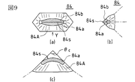
図9は、図7に示すスクライブヘッドの実施の形態に適用されるダイヤモンドカッターの他の例を示し、同図(a)は正面図、同図(b)は同図(a)の矢符X方向からみた側面図、同図(c)は同図(a)の矢符Y方向からみた側面図である。 FIG. 9 shows another example of the diamond cutter applied to the embodiment of the scribe head shown in FIG. 7, wherein FIG. 9A is a front view, and FIG. 9B is an arrow in FIG. The side view seen from the X direction and FIG. 10C are side views seen from the arrow Y direction of FIG.
このダイヤモンドカッター84は、図9(a)に示すように、貝殻状のいわゆるシェルタイプのダイヤモンドカッターであり、2つの傾斜面84a,84bによって刃先稜線84sが形成されている。このダイヤモンドカッター84は、図9(c)に示すように、へき開面84Aは90度の角θc に集束する辺をもち、刃先稜線84sは図9(a)の矢符Y方向からみて丸みをもつ形状とされている。
The
上記のスクライブヘッド70によりスクライブを行うにあたっては、支軸9をダイヤモンドカッター74に対し後側にしてスクライブヘッド70を脆性材料上を走行させる。つまり、図7における矢符Tで示す方向にスクライブヘッド70を走行させる。このように支軸9をダイヤモンドカッター74に対し後側にしてスクライブヘッドを走行させることで、図10に示すように、ダイヤモンドカッター74のカッティングポイント741、742、743、744あるいは刃先稜線84sがガラス板90の表面に接する点Pにおいて、走行方向に向かうスクライブ加工水平分力Vと、ガラス板90の厚み方向に向かうスクライブ加工垂直分力Wとの合力に対する反力Xが生じるが、この反力Xは支軸9に向かうものであって、ダイヤモンドカッター74をガラス板90表面から浮き上がらせるように作用する回転モーメントとはならない。これにより、前述したようなチップホルダの浮き上がり現象が発生せず、ダイヤモンドカッター74の刃先荷重が反力Xにより削がれてしまうことがない。その結果、ダイヤモンドカッター74の刃先荷重が効率よく脆性材料に作用することとなり、従来のものよりも格段に深い垂直クラックを得ることが可能となるのである。
In scribing with the
ここで、図10に示すように、ダイヤモンドカッター74がスクライブ中にガラス板90から受ける反力Xの方向が、該反力Xの起点Pと支軸9の軸心とを結ぶラインH上もしくは該ラインHよりガラス板90寄りに存する状態を維持するとよく(図10中、点線矢符X2 ,W2 ,V2 参照)、このようにすれば、前記回転モーメントの発生をより確実になくすことが可能となる。当該状態の維持にあたっては、スクライブ速度、ダイヤモンドカッター74に対する加圧力、ダイヤモンドカッター74と支軸9との相対位置関係を適宜調整することで行うことができる。
Here, as shown in FIG. 10, the direction of the reaction force X received from the
なお、ここではスクライブヘッド1及びスクライブヘッド50を備えたスクライブ装置について説明したが、このスクライブヘッド1に替えて、ダイヤモンドカッターを用いたスクライブヘッド70を備えたスクライブ装置についても本実施の形態に含まれる。その構成はスクライブヘッド以外については本実施の形態と同じであり、スクライブヘッド70については上述したので、詳細な説明は省略する。また、スクライブヘッド70を備えた装置構成による力学的作用は上述した図10に基づく説明が適用されることを記しておく。
In addition, although the scribe apparatus provided with the
次に、本発明に係るスクライブ方法と従来のスクライブ方法とをそれぞれ実施し、ガラスに形成された垂直クラックの深さを測定した。 Next, the scribing method according to the present invention and the conventional scribing method were carried out, and the depth of vertical cracks formed in the glass was measured.
(実施例)
本発明に係るスクライブ方法については、図4に示すスクライブヘッド60を用いて、次の条件でスクライブを行った。
カッターホイールチップのホイール径 2.5mm
カッターホイールチップのホイール厚 0.65mm
カッターホイールチップの刃先角度 125°
スクライブ速度 300mm/sec
刃先荷重 1.1kgf
ガラス板の材質 ソーダガラス
ガラス板の厚み 0.7mm
スクライブヘッドの走行方向 図4において矢符T方向
(Example)
About the scribing method according to the present invention, scribing was performed using the scribing head 60 shown in FIG. 4 under the following conditions.
Wheel diameter of cutter wheel tip 2.5mm
Cutter wheel tip wheel thickness 0.65mm
Cutter wheel tip edge angle 125 °
Scribe speed 300mm / sec
Cutting edge load 1.1kgf
Glass plate material Soda glass Glass plate thickness 0.7mm
Scribe head travel direction Arrow direction T in Fig. 4
(比較例)
比較として、スクライブヘッドの走行方向を従来通り、つまり図4において矢符Sの方向としてその他は、上記本発明の実施例と同条件で行った。但し、カッターホイールチップ5の回転軸13が、走行時に回動軸7の後側に位置するようチップホルダ4の向きを上記実施例とは逆にした。
(Comparative example)
For comparison, the traveling direction of the scribe head was the same as that of the conventional example, that is, the direction of the arrow S in FIG. However, the orientation of the
(測定結果)
上記各方法でスクライブした後、それぞれについて垂直クラックの深さを測定したところ、次の結果を得た。
実施例 450μm〜500μm
比較例 110μm〜120μm
以上の結果からも明らかなように、本実施例のスクライブ方法及びスクライブヘッドによれば、同じ刃先荷重で、比較例の約4倍以上にも達する深さの垂直クラックが得られることが解る。
(Measurement result)
After scribing by the above methods, the depth of vertical cracks was measured for each method, and the following results were obtained.
Example 450 μm to 500 μm
Comparative example 110 μm to 120 μm
As is apparent from the above results, according to the scribing method and scribing head of this example, it can be seen that vertical cracks having a depth that is about four times or more that of the comparative example can be obtained with the same edge load.
尚、上述の説明においては、脆性材料の一種であるガラス板にスクライブラインを形成する場合について主に述べたが、これに限ることなく、例えば液晶表示パネル、プラズマディスプレイパネル(PDP),有機ELディスプレイ等の脆性材料を貼り合わせたフラットパネルディスプレイ(FPD)や、透過型プロジェクタ基板、反射型プロジェクタ基板等のマザー貼り合わせ基板にスクライブラインを形成する工程に本発明のスクライブ方法及びスクライブヘッドが有効に適用される。 In the above description, the case where a scribe line is formed on a glass plate which is a kind of brittle material has been mainly described. However, the present invention is not limited to this. The scribing method and scribing head of the present invention are effective for forming a scribe line on a flat panel display (FPD) bonded with a brittle material such as a display, or a mother bonded substrate such as a transmissive projector substrate or a reflective projector substrate. Applies to
本発明のスクライブ方法及びスクライブヘッド並びにスクライブ装置は、スクライブラインを形成する垂直クラックが従来と比べて格段に深いものが得られ、特に、相互に交差するスクライブラインを脆性材料基板上に形成するのに好適であり、クロススクライブ後における分断工程において、スクライブラインに沿って容易に脆性材料基板を分断することができる点で有益である。また、不良品の発生をなくすことができ、生産効率を従来に比べて格段に向上させる点でも有益である。 The scribing method, scribing head, and scribing apparatus of the present invention can provide a scribe line that has a significantly deeper vertical crack than conventional ones. In particular, scribe lines that intersect each other are formed on a brittle material substrate. This is advantageous in that the brittle material substrate can be easily divided along the scribe line in the dividing step after the cross scribing. In addition, the occurrence of defective products can be eliminated, which is also advantageous in that the production efficiency is significantly improved as compared with the conventional case.
また、本発明によるスクライブラインの形成技術は、ガラス板のみならず、液晶表示パネル、PDP,FPD、透過型プロジェクタ基板、反射型プロジェクタ基板等のマザー貼り合わせ基板などにも適用可能である。 The scribe line forming technique according to the present invention is applicable not only to glass plates but also to mother bonded substrates such as liquid crystal display panels, PDPs, FPDs, transmissive projector substrates, and reflective projector substrates.
Claims (16)
Applications Claiming Priority (3)
| Application Number | Priority Date | Filing Date | Title |
|---|---|---|---|
| JP2002209823 | 2002-07-18 | ||
| JP2002209823 | 2002-07-18 | ||
| PCT/JP2003/009127 WO2004009311A1 (en) | 2002-07-18 | 2003-07-17 | Method of scribing on brittle matetrial, scribe head, and scribing apparatus with the scribe head |
Publications (2)
| Publication Number | Publication Date |
|---|---|
| JPWO2004009311A1 JPWO2004009311A1 (en) | 2005-11-17 |
| JP4205664B2 true JP4205664B2 (en) | 2009-01-07 |
Family
ID=30767701
Family Applications (1)
| Application Number | Title | Priority Date | Filing Date |
|---|---|---|---|
| JP2004522756A Expired - Fee Related JP4205664B2 (en) | 2002-07-18 | 2003-07-17 | Method of scribing brittle material, scribing head, and scribing apparatus equipped with the scribing head |
Country Status (6)
| Country | Link |
|---|---|
| JP (1) | JP4205664B2 (en) |
| KR (1) | KR100647456B1 (en) |
| CN (1) | CN1668431B (en) |
| AU (1) | AU2003281461A1 (en) |
| TW (1) | TW200403192A (en) |
| WO (1) | WO2004009311A1 (en) |
Cited By (1)
| Publication number | Priority date | Publication date | Assignee | Title |
|---|---|---|---|---|
| JP2017024349A (en) * | 2015-07-27 | 2017-02-02 | 三星ダイヤモンド工業株式会社 | Method for formation of vertical crack in brittle material substrate and method for segmentation of brittle material substrate |
Families Citing this family (10)
| Publication number | Priority date | Publication date | Assignee | Title |
|---|---|---|---|---|
| DE102005024497B4 (en) * | 2005-05-27 | 2008-06-19 | Schott Ag | Method for mechanically breaking scored flat workpieces from brittle material |
| CN102701580B (en) * | 2005-12-01 | 2014-10-08 | 三星钻石工业股份有限公司 | Method for replacing tip holder of Scribe device |
| US8051681B2 (en) * | 2007-05-09 | 2011-11-08 | Corning Incorporated | Constant force scoring device and method for using same |
| CN104149211B (en) * | 2007-06-06 | 2016-12-07 | 三星钻石工业株式会社 | Manual gas cutting cutter tip holder and there is the manual gas cutting cutter of this tip holder |
| JP5450964B2 (en) * | 2008-02-29 | 2014-03-26 | 三星ダイヤモンド工業株式会社 | Scribing apparatus and scribing method |
| KR100941080B1 (en) * | 2008-04-30 | 2010-02-10 | 세메스 주식회사 | Scribing apparatus and method, and apparatus for cutting substrate using the same |
| TWI498293B (en) * | 2011-05-31 | 2015-09-01 | Mitsuboshi Diamond Ind Co Ltd | Scribe method, diamond point and scribe apparatus |
| TWI562264B (en) * | 2012-12-19 | 2016-12-11 | Genesis Photonics Inc | Splitting apparatus and splitting method |
| CN107775825A (en) * | 2016-08-30 | 2018-03-09 | 三星钻石工业股份有限公司 | Diamond cutter and its scribble method |
| JP2018051945A (en) * | 2016-09-29 | 2018-04-05 | 三星ダイヤモンド工業株式会社 | Diamond tool and its scribing method |
Family Cites Families (4)
| Publication number | Priority date | Publication date | Assignee | Title |
|---|---|---|---|---|
| JPH0857846A (en) * | 1994-08-19 | 1996-03-05 | Hitachi Ltd | Diamond-point scribing device |
| JP4191304B2 (en) * | 1999-03-03 | 2008-12-03 | 三星ダイヤモンド工業株式会社 | Chip holder |
| JP4249373B2 (en) * | 2000-05-16 | 2009-04-02 | 三星ダイヤモンド工業株式会社 | Method for cross-scribing brittle materials |
| USRE41853E1 (en) * | 2001-07-18 | 2010-10-26 | Mitsuboshi Diamond Industrial Co., Ltd. | Scribing head, and scribing apparatus and scribing method using the scribing head |
-
2003
- 2003-07-17 AU AU2003281461A patent/AU2003281461A1/en not_active Abandoned
- 2003-07-17 CN CN038169444A patent/CN1668431B/en not_active Expired - Fee Related
- 2003-07-17 TW TW092119507A patent/TW200403192A/en not_active IP Right Cessation
- 2003-07-17 JP JP2004522756A patent/JP4205664B2/en not_active Expired - Fee Related
- 2003-07-17 WO PCT/JP2003/009127 patent/WO2004009311A1/en active Application Filing
- 2003-07-17 KR KR1020047020721A patent/KR100647456B1/en not_active IP Right Cessation
Cited By (1)
| Publication number | Priority date | Publication date | Assignee | Title |
|---|---|---|---|---|
| JP2017024349A (en) * | 2015-07-27 | 2017-02-02 | 三星ダイヤモンド工業株式会社 | Method for formation of vertical crack in brittle material substrate and method for segmentation of brittle material substrate |
Also Published As
| Publication number | Publication date |
|---|---|
| KR100647456B1 (en) | 2006-11-23 |
| KR20050013220A (en) | 2005-02-03 |
| TWI296612B (en) | 2008-05-11 |
| AU2003281461A1 (en) | 2004-02-09 |
| TW200403192A (en) | 2004-03-01 |
| JPWO2004009311A1 (en) | 2005-11-17 |
| WO2004009311A1 (en) | 2004-01-29 |
| CN1668431A (en) | 2005-09-14 |
| CN1668431B (en) | 2010-06-09 |
Similar Documents
| Publication | Publication Date | Title |
|---|---|---|
| JP4118804B2 (en) | Scribing head, scribing apparatus using the scribing head, and scribing method for brittle material substrate | |
| JP5328049B2 (en) | Substrate cutting apparatus and substrate cutting method | |
| US8029879B2 (en) | Display device having pair of glass substrates and method for cutting it | |
| JP4711829B2 (en) | Scribing line forming mechanism, scribing head and scribing device | |
| KR100889308B1 (en) | Scribing apparatus and method, apparatus for cutting substrate using the scribing apparatus | |
| KR100682832B1 (en) | Method and device for scribing fragile material substrate | |
| JP4205664B2 (en) | Method of scribing brittle material, scribing head, and scribing apparatus equipped with the scribing head | |
| EP1475357B1 (en) | Fragile material substrate parting system | |
| TWI462885B (en) | Method of breaking the substrate | |
| JP6551661B2 (en) | Method and apparatus for scribing brittle material substrate | |
| KR100665104B1 (en) | A scribing head, a scribing method for brittle materials and a scribing apparatus therefor | |
| JP5444158B2 (en) | Cleaving method of brittle material substrate | |
| JP2020050570A (en) | Scribing method | |
| JP4081013B2 (en) | Cutter wheel for brittle material, scribing device using the cutter wheel, and scribing method using the cutter wheel | |
| JP2006151761A (en) | Cutting device for glass substrate | |
| JP2001261356A (en) | Scribing head | |
| KR20090052836A (en) | Scribing apparatus and apparatus for cutting substrate using the scribing apparatus |
Legal Events
| Date | Code | Title | Description |
|---|---|---|---|
| A131 | Notification of reasons for refusal |
Free format text: JAPANESE INTERMEDIATE CODE: A131 Effective date: 20080226 |
|
| A521 | Written amendment |
Free format text: JAPANESE INTERMEDIATE CODE: A523 Effective date: 20080425 |
|
| TRDD | Decision of grant or rejection written | ||
| A01 | Written decision to grant a patent or to grant a registration (utility model) |
Free format text: JAPANESE INTERMEDIATE CODE: A01 Effective date: 20080916 |
|
| A01 | Written decision to grant a patent or to grant a registration (utility model) |
Free format text: JAPANESE INTERMEDIATE CODE: A01 |
|
| A61 | First payment of annual fees (during grant procedure) |
Free format text: JAPANESE INTERMEDIATE CODE: A61 Effective date: 20081016 |
|
| FPAY | Renewal fee payment (event date is renewal date of database) |
Free format text: PAYMENT UNTIL: 20111024 Year of fee payment: 3 |
|
| R150 | Certificate of patent or registration of utility model |
Free format text: JAPANESE INTERMEDIATE CODE: R150 |
|
| LAPS | Cancellation because of no payment of annual fees |