EP1553487A1 - Décodage m-matrice et correction d'erreurs - Google Patents
Décodage m-matrice et correction d'erreurs Download PDFInfo
- Publication number
- EP1553487A1 EP1553487A1 EP05000170A EP05000170A EP1553487A1 EP 1553487 A1 EP1553487 A1 EP 1553487A1 EP 05000170 A EP05000170 A EP 05000170A EP 05000170 A EP05000170 A EP 05000170A EP 1553487 A1 EP1553487 A1 EP 1553487A1
- Authority
- EP
- European Patent Office
- Prior art keywords
- bits
- extracted
- error
- decoding
- subset
- Prior art date
- Legal status (The legal status is an assumption and is not a legal conclusion. Google has not performed a legal analysis and makes no representation as to the accuracy of the status listed.)
- Ceased
Links
Images


Classifications
-
- G—PHYSICS
- G06—COMPUTING; CALCULATING OR COUNTING
- G06T—IMAGE DATA PROCESSING OR GENERATION, IN GENERAL
- G06T1/00—General purpose image data processing
-
- G—PHYSICS
- G06—COMPUTING; CALCULATING OR COUNTING
- G06F—ELECTRIC DIGITAL DATA PROCESSING
- G06F3/00—Input arrangements for transferring data to be processed into a form capable of being handled by the computer; Output arrangements for transferring data from processing unit to output unit, e.g. interface arrangements
- G06F3/01—Input arrangements or combined input and output arrangements for interaction between user and computer
- G06F3/03—Arrangements for converting the position or the displacement of a member into a coded form
- G06F3/033—Pointing devices displaced or positioned by the user, e.g. mice, trackballs, pens or joysticks; Accessories therefor
- G06F3/0354—Pointing devices displaced or positioned by the user, e.g. mice, trackballs, pens or joysticks; Accessories therefor with detection of 2D relative movements between the device, or an operating part thereof, and a plane or surface, e.g. 2D mice, trackballs, pens or pucks
- G06F3/03545—Pens or stylus
-
- G—PHYSICS
- G06—COMPUTING; CALCULATING OR COUNTING
- G06F—ELECTRIC DIGITAL DATA PROCESSING
- G06F3/00—Input arrangements for transferring data to be processed into a form capable of being handled by the computer; Output arrangements for transferring data from processing unit to output unit, e.g. interface arrangements
- G06F3/01—Input arrangements or combined input and output arrangements for interaction between user and computer
- G06F3/03—Arrangements for converting the position or the displacement of a member into a coded form
- G06F3/0304—Detection arrangements using opto-electronic means
- G06F3/0317—Detection arrangements using opto-electronic means in co-operation with a patterned surface, e.g. absolute position or relative movement detection for an optical mouse or pen positioned with respect to a coded surface
- G06F3/0321—Detection arrangements using opto-electronic means in co-operation with a patterned surface, e.g. absolute position or relative movement detection for an optical mouse or pen positioned with respect to a coded surface by optically sensing the absolute position with respect to a regularly patterned surface forming a passive digitiser, e.g. pen optically detecting position indicative tags printed on a paper sheet
-
- G—PHYSICS
- G06—COMPUTING; CALCULATING OR COUNTING
- G06T—IMAGE DATA PROCESSING OR GENERATION, IN GENERAL
- G06T7/00—Image analysis
- G06T7/40—Analysis of texture
Definitions
- the present invention relates to interacting with a medium using a digital pen. More particularly, the present invention relates to determining the location of a digital pen during interaction with one or more surfaces.
- One technique of capturing handwritten information is by using a pen whose location may be determined during writing.
- One pen that provides this capability is the Anoto pen by Anoto Inc.
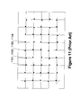
- This pen functions by using a camera to capture an image of paper encoded with a predefined pattern. An example of the image pattern is shown in Figure 11.
- This pattern is used by the Anoto pen (by Anoto Inc.) to determine a location of a pen on a piece of paper.
- it is unclear how efficient the determination of the location is with the system used by the Anoto pen.
- a system is needed that provides efficient decoding of the captured image.
- aspects of the present invention provide solutions to at least one of the issues mentioned above, thereby enabling one to locate a position or positions of the captured image on a viewed document with a predefined pattern.
- the viewed document may be on paper, LCD screen or any other medium with the predefined pattern.
- aspects of the present invention include a decoding process that permits efficient decoding of a captured image, providing for efficient determination of the location of the image.
- a decoding process tactfully selects a subset of bits from bits extracted from the captured image.
- a process adjusts the number of iterations that the decoding process executes.
- a process determines the X,Y coordinates of the location of the extracted bits so that the X,Y coordinates are consistent with a local constraint such as a destination area.
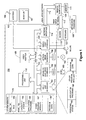
- Figure 1 shows a general description of a computer that may be used in conjunction with embodiments of the present invention.
- Figures 2A and 2B show an image capture system and corresponding captured image in accordance with embodiments of the present invention.
- FIGS 3A through 3F show various sequences and folding techniques in accordance with embodiments of the present invention.
- FIGS. 4A through 4E show various encoding systems in accordance with embodiments of the present invention.
- Figures 5A through 5D show four possible resultant corners associated with the encoding system according to Figures 4A and 4B.
- Figure 6 shows rotation of a captured image portion in accordance with embodiments of the present invention.
- Figure 7 shows various angles of rotation used in conjunction with the coding system of Figures 4A through 4E.
- Figure 8 shows a process for determining the location of a captured array in accordance with embodiments of the present invention.
- Figure 9 shows a method for determining the location of a captured image in accordance with embodiments of the present invention.
- Figure 10 shows another method for determining the location of captured image in accordance with embodiments of the present invention.
- Figure 11 shows a representation of encoding space in a document according to prior art.
- Figure 12 shows a flow diagram for decoding extracted bits from a captured image in accordance with embodiments of the present invention.
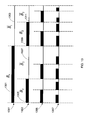
- Figure 13 shows bit selection of extracted bits from a captured image in accordance with embodiments of the present invention.
- Figure 14 shows an apparatus for decoding extracted bits from a captured image in accordance with embodiments of the present invention.
- aspects of the present invention relate to determining the location of a captured image in relation to a larger image.
- the location determination method and system described herein may be used in combination with a multi-function pen.
- the following is separated by subheadings for the benefit of the reader.
- the subheadings include: terms, general-purpose computer, image capturing pen, encoding of array, decoding, error correction, and location determination.
- Pen - any writing implement that may or may not include the ability to store ink.
- a stylus with no ink capability may be used as a pen in accordance with embodiments of the present invention.
- Camera - an image capture system that may capture an image from paper or any other medium.
- FIG. 1 is a functional block diagram of an example of a conventional general-purpose digital computing environment that can be used to implement various aspects of the present invention.
- a computer 100 includes a processing unit 110, a system memory 120, and a system bus 130 that couples various system components including the system memory to the processing unit 110.
- the system bus 130 may be any of several types of bus structures including a memory bus or memory controller, a peripheral bus, and a local bus using any of a variety of bus architectures.
- the system memory 120 includes read only memory (ROM) 140 and random access memory (RAM) 150.
- a basic input/output system 160 (BIOS), containing the basic routines that help to transfer information between elements within the computer 100, such as during start-up, is stored in the ROM 140.
- the computer 100 also includes a hard disk drive 170 for reading from and writing to a hard disk (not shown), a magnetic disk drive 180 for reading from or writing to a removable magnetic disk 190, and an optical disk drive 191 for reading from or writing to a removable optical disk 192 such as a CD ROM or other optical media.
- the hard disk drive 170, magnetic disk drive 180, and optical disk drive 191 are connected to the system bus 130 by a hard disk drive interface 192, a magnetic disk drive interface 193, and an optical disk drive interface 194, respectively.
- the drives and their associated computer-readable media provide nonvolatile storage of computer readable instructions, data structures, program modules and other data for the personal computer 100. It will be appreciated by those skilled in the art that other types of computer readable media that can store data that is accessible by a computer, such as magnetic cassettes, flash memory cards, digital video disks, Bernoulli cartridges, random access memories (RAMs), read only memories (ROMs), and the like, may also be used in the example operating environment.
- RAMs random access memories
- ROMs read only memories
- a number of program modules can be stored on the hard disk drive 170, magnetic disk 190, optical disk 192, ROM 140 or RAM 150, including an operating system 195, one or more application programs 196, other program modules 197, and program data 198.
- a user can enter commands and information into the computer 100 through input devices such as a keyboard 101 and pointing device 102.
- Other input devices may include a microphone, joystick, game pad, satellite dish, scanner or the like.
- These and other input devices are often connected to the processing unit 110 through a serial port interface 106 that is coupled to the system bus, but may be connected by other interfaces, such as a parallel port, game port or a universal serial bus (USB).
- USB universal serial bus
- these devices may be coupled directly to the system bus 130 via an appropriate interface (not shown).
- a monitor 107 or other type of display device is also connected to the system bus 130 via an interface, such as a video adapter 108.
- personal computers typically include other peripheral output devices (not shown), such as speakers and printers.
- a pen digitizer 165 and accompanying pen or stylus 166 are provided in order to digitally capture freehand input.
- the pen digitizer 165 may be coupled to the processing unit 110 directly, via a parallel port or other interface and the system bus 130 as known in the art.
- the digitizer 165 is shown apart from the monitor 107, it is preferred that the usable input area of the digitizer 165 be co-extensive with the display area of the monitor 107. Further still, the digitizer 165 may be integrated in the monitor 107, or may exist as a separate device overlaying or otherwise appended to the monitor 107.
- the computer 100 can operate in a networked environment using logical connections to one or more remote computers, such as a remote computer 109.
- the remote computer 109 can be a server, a router, a network PC, a peer device or other common network node, and typically includes many or all of the elements described above relative to the computer 100, although only a memory storage device 111 has been illustrated in Figure 1.
- the logical connections depicted in Figure 1 include a local area network (LAN) 112 and a wide area network (WAN) 113.
- LAN local area network
- WAN wide area network
- the computer 100 When used in a LAN networking environment, the computer 100 is connected to the local network 112 through a network interface or adapter 114. When used in a WAN networking environment, the personal computer 100 typically includes a modem 115 or other means for establishing a communications over the wide area network 113, such as the Internet.
- the modem 115 which may be internal or external, is connected to the system bus 130 via the serial port interface 106.
- program modules depicted relative to the personal computer 100, or portions thereof, may be stored in the remote memory storage device.
- network connections shown are illustrative and other techniques for establishing a communications link between the computers can be used.
- the existence of any of various well-known protocols such as TCP/IP, Ethernet, FTP, HTTP, Bluetooth, IEEE 802.11x and the like is presumed, and the system can be operated in a client-server configuration to permit a user to retrieve web pages from a web-based server.
- Any of various conventional web browsers can be used to display and manipulate data on web pages.
- aspects of the present invention include placing an encoded data stream in a displayed form that represents the encoded data stream.
- the displayed form may be printed paper (or other physical medium) or may be a display projecting the encoded data stream in conjunction with another image or set of images.
- the encoded data stream may be represented as a physical graphical image on the paper or a graphical image overlying the displayed image (e.g., representing the text of a document) or may be a physical (non-modifiable) graphical image on a display screen (so any image portion captured by a pen is locatable on the display screen).
- the pen may be an ink pen writing on paper.
- the pen may be a stylus with the user writing on the surface of a computer display. Any interaction may be provided back to the system with knowledge of the encoded image on the document or supporting the document displayed on the computer screen.
- the displayed or printed image may be a watermark associated with the blank or content-rich paper or may be a watermark associated with a displayed image or a fixed coding overlying a screen or built into a screen.
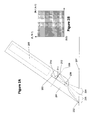
- FIGS 2A and 2B show an illustrative example of pen 201 with a camera 203.
- Pen 201 includes a tip 202 that may or may not include an ink reservoir.
- Camera 203 captures an image 204 from surface 207.
- Pen 201 may further include additional sensors and/or processors as represented in broken box 206. These sensors and/or processors 206 may also include the ability to transmit information to another pen 201 and/or a personal computer (for example, via Bluetooth or other wireless protocols).
- Figure 2B represents an image as viewed by camera 203.
- the field of view of camera 203 i.e., the resolution of the image sensor of the camera
- a captured image 32 pixels by 32 pixels
- Figure 2B shows a field of view of 32 pixels long by 32 pixels wide.
- the size of N is adjustable, such that a larger N corresponds to a higher image resolution.
- the field of view of the camera 203 is shown as a square for illustrative purposes here, the field of view may include other shapes as is known in the art.
- the images captured by camera 203 may be defined as a sequence of image frames ⁇ I i ⁇ , where I i is captured by the pen 201 at sampling time t i .
- the sampling rate may be large or small, depending on system configuration and performance requirement.
- the size of the captured image frame may be large or small, depending on system configuration and performance requirement.
- the image captured by camera 203 may be used directly by the processing system or may undergo pre-filtering. This pre-filtering may occur in pen 201 or may occur outside of pen 201 (for example, in a personal computer).
- the image size of Figure 2B is 32x32 pixels. If each encoding unit size is 3x3 pixels, then the number of captured encoded units would be approximately 100 units. If the encoding unit size is 5x5 pixels, then the number of captured encoded units is approximately 36.
- Figure 2A also shows the image plane 209 on which an image 210 of the pattern from location 204 is formed.
- Light received from the pattern on the object plane 207 is focused by lens 208.
- Lens 208 may be a single lens or a multi-part lens system, but is represented here as a single lens for simplicity.
- Image capturing sensor 211 captures the image 210.
- the image sensor 211 may be large enough to capture the image 210.
- the image sensor 211 may be large enough to capture an image of the pen tip 202 at location 212.
- the image at location 212 is referred to as the virtual pen tip. It is noted that the virtual pen tip location with respect to image sensor 211 is fixed because of the constant relationship between the pen tip, the lens 208, and the image sensor 211.
- the transformation F S ⁇ P may be estimated as an affine transform. This simplifies as: as the estimation of F S ⁇ P , in which ⁇ x , ⁇ y , s x , and s y are the rotation and scale of two orientations of the pattern captured at location 204. Further, one can refine F' S ⁇ P by matching the captured image with the corresponding real image on paper. "Refine” means to get a more precise estimation of the transformation F S ⁇ P by a type of optimization algorithm referred to as a recursive method. The recursive method treats the matrix F' S ⁇ P as the initial value. The refined estimation describes the transformation between S and P more precisely.
- a location of the virtual pen tip L virtual-pentip may be determined.
- L virtual-pentip one can get a more accurate estimation of L pentip .
- an accurate location of virtual pen tip L virtual-pentip may be determined.
- a two-dimensional array may be constructed by folding a one-dimensional sequence. Any portion of the two-dimensional array containing a large enough number of bits may be used to determine its location in the complete two-dimensional array. However, it may be necessary to determine the location from a captured image or a few captured images. So as to minimize the possibility of a captured image portion being associated with two or more locations in the two-dimensional array, a non-repeating sequence may be used to create the array.
- One property of a created sequence is that the sequence does not repeat over a length (or window) n . The following describes the creation of the one-dimensional sequence then the folding of the sequence into an array.
- a sequence of numbers may be used as the starting point of the encoding system.
- a sequence (also referred to as an m -sequence) may be represented as a q-element set in field F q .
- q p n where n ⁇ 1 and p is a prime number.
- the sequence or m -sequence may be generated by a variety of different techniques including, but not limited to, polynomial division. Using polynomial division, the sequence may be defined as follows: R l ( x ) P n ( x )
- P n (x) is a primitive polynomial of degree n in field F q [x] (having q n elements).
- R l (x) is a nonzero polynomial of degree l (where l ⁇ n ) in field F q [x] .
- the sequence may be created using an iterative procedure with two steps: first, dividing the two polynomials (resulting in an element of field F q ) and, second, multiplying the remainder by x. The computation stops when the output begins to repeat. This process may be implemented using a linear feedback shift register as set forth in an article by Douglas W.
- the array (or m -array) that may be used to create the image (of which a portion may be captured by the camera) is an extension of the one-dimensional sequence or m -sequence.
- a widow property is also referred to as a "window property" in that each window is unique.
- a widow may then be expressed as an array of period (m 1 , m 2 ) (with m 1 and m 2 being the horizontal and vertical number of bits present in the array) and order (n 1 , n 2 ) .
- a binary array may be constructed by folding the sequence.
- one may start with a predetermined size of the space that one wants to cover (for example, one sheet of paper, 30 sheets of paper or the size of a computer monitor), determine the area ( m 1 ⁇ m 2 ), then use the size to let L ⁇ m 1 ⁇ m 2 , where L 2 n - 1.
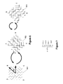
- Figures 3A through 3C show three different sequences. Each of these may be folded into the array shown as Figure 3D.
- the three different folding methods are shown as the overlay in Figure 3D and as the raster paths in Figures 3E and 3F. We adopt the folding method shown in Figure 3D.
- This folding approach may be alternatively expressed as laying the sequence on the diagonal of the array, then continuing from the opposite edge when an edge is reached.
- Figure 4A shows sample encoding techniques that may be used to encode the array of Figure 3D. It is appreciated that other encoding techniques may be used. For example, an alternative coding technique is shown in Figure 11.
- a first bit 401 (for example, "1") is represented by a column of dark ink.
- a second bit 402 (for example, "0") is represented by a row of dark ink.
- any color ink may be used to represent the various bits. The only requirement in the color of the ink chosen is that it provides a significant contrast with the background of the medium to be differentiable by an image capture system.
- the bits in Figure 4A are represented by a 3x3 matrix of cells. The size of the matrix may be modified to be any size as based on the size and resolution of an image capture system.
- Alternative representation of bits 0 and 1 are shown in Figures 4C-4E.
- Figure 4C shows bit representations occupying two rows or columns in an interleaved arrangement.
- Figure 4D shows an alternative arrangement of the pixels in rows and columns in a dashed form.
- Figure 4E shows pixel representations in columns and rows in an irregular spacing format (e.g., two dark dots followed by a blank dot).
- more than one pixel or dot is used to represent a bit.
- Using a single pixel (or bit) to represent a bit is fragile. Dust, creases in paper, non-planar surfaces, and the like create difficulties in reading single bit representations of data units.
- different approaches may be used to graphically represent the array on a surface. Some approaches are shown in Figures 4C through 4E. It is appreciated that other approaches may be used as well.
- One approach is set forth in Figure 11 using only space-shifted dots.
- a bit stream is used to create the graphical pattern 403 of Figure 4B.
- Graphical pattern 403 includes 12 rows and 18 columns. The rows and columns are formed by a bit stream that is converted into a graphical representation using bit representations 401 and 402.
- Figure 4B may be viewed as having the following bit representation:
- pen 201 may utilize a pressure sensor as pen 201 is pressed against paper and pen 201 traverses a document on the paper.
- the image is then processed to determine the orientation of the captured image with respect to the complete representation of the encoded image and extract the bits that make up the captured image.
- the image captured by a camera 601 may be analyzed and its orientation determined so as to be interpretable as to the position actually represented by the image 601.
- image 601 is reviewed to determine the angle ⁇ needed to rotate the image so that the pixels are horizontally and vertically aligned.
- alternative grid alignments are possible including a rotation of the underlying grid to a non-horizontal and vertical arrangement (for example, 45 degrees).
- Using a non-horizontal and vertical arrangement may provide the probable benefit of eliminating visual distractions from the user, as users may tend to notice horizontal and vertical patterns before others.
- the orientation of the grid (horizontal and vertical and any other rotation of the underlying grid) is referred to collectively as the predefined grid orientation.
- image 601 is analyzed to determine which corner is missing.
- the rotation amount is shown by the equation in Figure 7.
- angle ⁇ is first determined by the layout of the pixels to arrive at a horizontal and vertical (or other predefined grid orientation) arrangement of the pixels and the image is rotated as shown in 602.
- An analysis is then conducted to determine the missing corner and the image 602 rotated to the image 603 to set up the image for decoding.
- the image is rotated 90 degrees counterclockwise so that image 603 has the correct orientation and can be used for decoding.
- rotation angle ⁇ may be applied before or after rotation of the image 601 to account for the missing corner. It is also appreciated that by considering noise in the captured image, all four types of corners may be present. We may count the number of corners of each type and choose the type that has the least number as the corner type that is missing.
- the code in image 603 is read out and correlated with the original bit stream used to create image 403.
- the correlation may be performed in a number of ways. For example, it may be performed by a recursive approach in which a recovered bit stream is compared against all other bit stream fragments within the original bit stream. Second, a statistical analysis may be performed between the recovered bit stream and the original bit stream, for example, by using a Hamming distance between the two bit streams. It is appreciated that a variety of approaches may be used to determine the location of the recovered bit stream within the original bit stream.
- the image capture system may need to function with non-sequential bits extracted from the image. The following represents a method for operating with non-sequential bits from the image.
- the location s of the K bits is just the number of cyclic shifts of I so that b 0 is shifted to the beginning of the sequence.
- T the cyclic shift operator.
- the polynomials modulo P n (x) form a field. It is guaranteed that x s ⁇ r 0 + r 1 x + ⁇ r n -1 x n -1 mod( P n ( x )) . Therefore, we may find ( r 0 , r 1 , ⁇ , r n -1 ) and then solve for s.
- the Hamming distance between b t and r t M , or the number of error bits associated with r should be minimal, where r is computed via equation (4). Repeating the process for several times, it is likely that the correct r that results in the minimal error bits can be identified.
- the system then may move on to process the next captured image.
- information about previous locations of the pen can be taken into consideration. That is, for each captured image, a destination area where the pen may be expected next can be identified. For example, if the user has not lifted the pen between two image captures by the camera, the location of the pen as determined by the second image capture should not be too far away from the first location.
- Each r that is associated with the minimum number of error bits can then be checked to see if the location s computed from r satisfies the local constraint, i.e., whether the location is within the destination area specified.
- the decoding process fails.
- Figure 8 depicts a process that may be used to determine a location in a sequence (or m -sequence) of a captured image.
- a data stream relating to a captured image is received.
- corresponding columns are extracted from A and a matrix M is constructed.
- step 803 n independent column vectors are randomly selected from the matrix M and vector r is determined by solving equation (4). This process is performed Q times (for example, 100 times) in step 804. The determination of the number of loop times is discussed in the section Loop Times Calculation.
- r is sorted according to its associated number of error bits.
- the sorting can be done using a variety of sorting algorithms as known in the art. For example, a selection sorting algorithm may be used. The selection sorting algorithm is beneficial when the number Q is not large. However, if Q becomes large, other sorting algorithms (for example, a merge sort) that handle larger numbers of items more efficiently may be used.
- step 806 determines in step 806 whether error correction was performed successfully, by checking whether multiple r 's are associated with the minimum number of error bits. If yes, an error is returned in step 809, indicating the decoding process failed. If not, the position s of the extracted bits in the sequence (or m -sequence) is calculated in step 807, for example, by using the Pohig-Hellman-Silver algorithm.
- Figure 9 shows a process for determining the location of a pen tip.
- the input is an image captured by a camera and the output may be a position coordinates of the pen tip. Also, the output may include (or not) other information such as a rotation angle of the captured image.
- step 901 an image is received from a camera.
- the received image may be optionally preprocessed in step 902 (as shown by the broken outline of step 902) to adjust the contrast between the light and dark pixels and the like.
- step 903 the image is analyzed to determine the bit stream within it.
- n bits are randomly selected from the bit stream for multiple times and the location of the received bit stream within the original sequence (or m -sequence) is determined.
- step 904 the location of the pen tip may be determined in step 905.
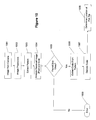
- Figure 10 gives more details about 903 and 904 and shows the approach to extract the bit stream within a captured image.
- an image is received from the camera in step 1001.
- the image then may optionally undergo image preprocessing in step 1002 (as shown by the broken outline of step 1002).
- the pattern is extracted in step 1003.
- pixels on the various lines may be extracted to find the orientation of the pattern and the angle ⁇ .
- step 1004 the received image is analyzed in step 1004 to determine the underlying grid lines. If grid lines are found in step 1005, then the code is extracted from the pattern in step 1006. The code is then decoded in step 1007 and the location of the pen tip is determined in step 1008. If no grid lines were found in step 1005, then an error is returned in step 1009.
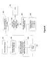
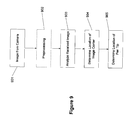
- FIG 12 shows a flow diagram of process 1200 of this enhanced approach.
- Process 1200 comprises two components 1251 and 1253.
- the embodiment of the invention utilizes a discreet strategy to select bits, adjusts the number of loop iterations, and determines the X,Y position (location coordinates) in accordance with a local constraint, which is provided to process 1200.
- steps 1205 and 1219 (“Decode Once") utilize equation (4) to compute r .
- FIG. 12 shows a flow diagram of process 1200 for decoding extracted bits 1201 from a captured image in accordance with embodiments of the present invention.
- Process 1200 comprises components 1251 and 1253.
- Component 1251 obtains extracted bits 1201 (comprising K bits) associated with a captured image (corresponding to a captured array).
- n bits (where n is the order of the m -array) are randomly selected from extracted bits 1201.
- process 1200 decodes once and calculates r.
- process 1200 determines if error bits are detected for b . If step 1207 determines that there are no error bits, X,Y coordinates of the position of the captured array are determined in step 1209.
- step 1211 if the X,Y coordinates satisfy the local constraint, i.e., coordinates that are within the destination area, process 1200 provides the X,Y position (such as to another process or user interface) in step 1213. Otherwise, step 1215 provides a failure indication.
- step 1207 detects error bits in b
- component 1253 is executed in order to decode with error bits.
- Step 1217 selects another set of n bits (which differ by at least one bit from the n bits selected in step 1203) from extracted bits 1201.
- Steps 1221 and 1223 determine the number of iterations (loop times) that are necessary for decoding the extracted bits.
- Step 1225 determines the position of the captured array by testing which candidates obtained in step 1219 satisfy the local constraint. Steps 1217-1225 will be discussed in more details.
- Step 1203 randomly selects n bits from extracted bits 1201 (having K bits), and solves for r 1 .
- decoded bits can be calculated. Let where b and k is the k th bit of b and , and that is, B 1 are bits that the decoded results are the same as the original bits, and B 1 are bits that the decoded results are different from the original bits, I 1 and I 1 are the corresponding indices of these bits. It is appreciated that the same r 1 will be obtained when any n bits are selected from B 1 . Therefore, if the next n bits are not carefully chosen, it is possible that the selected bits are a subset of B 1 , thus resulting in the same r 1 being obtained.
- step 1217 selects the next n bits according to the following procedure:
- the error correction component 1253 With the error correction component 1253, the number of required iterations (loop times) is adjusted after each loop. The loop times is determined by the expected error rate.
- the decoded position should be within the destination area.
- the destination area is an input to the algorithm, and it may be of various sizes and places or simply the whole m -array depending on different applications. Usually it can be predicted by the application. For example, if the previous position is determined, considering the writing speed, the destination area of the current pen tip should be close to the previous position. However, if the pen is lifted, then its next position can be anywhere. Therefore, in this case, the destination area should be the whole m -array.
- the correct X,Y position is determined by the following steps.
- Step 1224 sorts r i in ascending order of the number of error bits. Steps 1225, 1211 and 1212 then finds the first r i in which the corresponding X,Y position is within the destination area. Steps 1225, 1211 and 1212 finally returns the X,Y position as the result (through step 1213), or an indication that the decoding procedure failed (through step 1215).
- An illustrative example demonstrates process 1200 as performed by components 1251 and 1253.
- step 1209 determines the X,Y position and step 1211 determines whether the decoded position is inside the destination area. If so, the decoding is successful, and step 1213 is performed. Otherwise, the decoding fails as indicated by step 1215. If b and 1 is different from b, then error bits in b are detected and component 1253 is performed.
- Step 1217 determines the set B 1 , say ⁇ b 0 b 1 b 2 b 3 ⁇ , where the decoded bits are the same as the original bits.
- B 1 ⁇ b 4 ⁇ (corresponding to bit arrangement 1351 in Figure 13).
- Loop times ( lt ) is initialized to a constant, e.g., 100, which may be variable depending on the application. Note that the number of error bits corresponding to r 1 is equal to 1.
- Step 1219 solves for r 2 : where consists of the 0 th , 1 st , and 4 th columns of M .
- B 2 e.g., ⁇ b 0 b 1 b 4 ⁇ , such that b and 2 and b are the same.
- B 2 ⁇ b 2 b 3 ⁇ (corresponding to bit arrangement 1353 in Figure 13).
- the selected bits shall not all belong to either B 1 or B 2 . So step 1217 may select, for example, one bit ⁇ b 4 ⁇ from B 1 , one bit ⁇ b 2 ⁇ from B 2 , and the remaining one bit ⁇ b 0 ⁇ .
- Step 1224 selects r i 's, for example, r 1 , r 2 , r 4 , r 5 , whose corresponding numbers of error bits are less than N e shown in (8).
- Step 1224 sorts the selected vectors r 1 , r 2 , r 4 , r 5 in ascending order of their error bit numbers: r 1 , r 2 , r 5 , r 4 . From the sorted candidate list, steps 1225, 1211 and 1212 find the first vector r, for example, r 5 , whose corresponding position is within the destination area. Step 1213 then outputs the corresponding position. If none of the positions is within the destination area, the decoding process fails as indicated by step 1215.
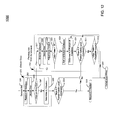
- Figure 14 shows an apparatus 1400 for decoding extracted bits 1201 from a captured array in accordance with embodiments of the present invention.
- Apparatus 1400 comprises bit selection module 1401, decoding module 1403, position determination module 1405, input interface 1407, and output interface 1409.
- interface 1407 may receive extracted bits 1201 from different sources, including a module that supports camera 203 (as shown in Figure 2A).
- Bit selection module 1401 selects n bits from extracted bits 1201 in accordance with steps 1203 and 1217.
- Decoding module 1403 decodes the selected bits ( n bits selected from the K extracted bits as selected by bit selection module 1401) to determine detected bit errors and corresponding vectors r i in accordance with steps 1205 and 1219.
- Decoding module 1403 presents the determined vectors r i to position determination module 1405.
- Position determination module 1405 determines the X,Y coordinates of the captured array in accordance with steps 1209 and 1225.
- Position determination module 1405 presents the results, which includes the X,Y coordinates if successful and an error indication if not successful, to output interface 1409.
- Output interface 1409 may present the results to another module that may perform further processing or that may display the results.
- Apparatus 1400 may assume different forms of implementation, including modules utilizing computer-readable media and modules utilizing specialized hardware such as an application specific integrated circuit (ASIC).
- ASIC application specific integrated circuit
- the computer system may include at least one computer such as a microprocessor, digital signal processor, and associated peripheral electronic circuitry.
Applications Claiming Priority (2)
| Application Number | Priority Date | Filing Date | Title |
|---|---|---|---|
| US752109 | 2004-01-06 | ||
| US10/752,109 US7583842B2 (en) | 2004-01-06 | 2004-01-06 | Enhanced approach of m-array decoding and error correction |
Publications (1)
| Publication Number | Publication Date |
|---|---|
| EP1553487A1 true EP1553487A1 (fr) | 2005-07-13 |
Family
ID=34592558
Family Applications (1)
| Application Number | Title | Priority Date | Filing Date |
|---|---|---|---|
| EP05000170A Ceased EP1553487A1 (fr) | 2004-01-06 | 2005-01-05 | Décodage m-matrice et correction d'erreurs |
Country Status (10)
| Country | Link |
|---|---|
| US (1) | US7583842B2 (fr) |
| EP (1) | EP1553487A1 (fr) |
| JP (2) | JP4833555B2 (fr) |
| KR (1) | KR101122822B1 (fr) |
| CN (1) | CN1744104B (fr) |
| AU (1) | AU2004242549A1 (fr) |
| BR (1) | BRPI0500013A (fr) |
| CA (1) | CA2491579C (fr) |
| MX (1) | MXPA05000369A (fr) |
| RU (1) | RU2380736C2 (fr) |
Cited By (3)
| Publication number | Priority date | Publication date | Assignee | Title |
|---|---|---|---|---|
| WO2007146776A2 (fr) | 2006-06-14 | 2007-12-21 | Hewlett-Packard Development Company, L.P. | Localisation de position en utilisant une correction d'erreur |
| EP2169357A1 (fr) | 2008-09-24 | 2010-03-31 | CSEM Centre Suisse d'Electronique et de Microtechnique SA Recherche et Développement | Codeur de position bidimensionnel |
| CN101319923B (zh) * | 2008-07-09 | 2011-05-11 | 浙江工贸职业技术学院 | 笔的书写性能测试方法 |
Families Citing this family (20)
| Publication number | Priority date | Publication date | Assignee | Title |
|---|---|---|---|---|
| US7009594B2 (en) * | 2002-10-31 | 2006-03-07 | Microsoft Corporation | Universal computing device |
| US7133563B2 (en) | 2002-10-31 | 2006-11-07 | Microsoft Corporation | Passive embedded interaction code |
| US7505982B2 (en) * | 2004-12-03 | 2009-03-17 | Microsoft Corporation | Local metadata embedding solution |
| US7536051B2 (en) * | 2005-02-17 | 2009-05-19 | Microsoft Corporation | Digital pen calibration by local linearization |
| US7607076B2 (en) * | 2005-02-18 | 2009-10-20 | Microsoft Corporation | Embedded interaction code document |
| US7826074B1 (en) | 2005-02-25 | 2010-11-02 | Microsoft Corporation | Fast embedded interaction code printing with custom postscript commands |
| US7532366B1 (en) | 2005-02-25 | 2009-05-12 | Microsoft Corporation | Embedded interaction code printing with Microsoft Office documents |
| US7421439B2 (en) * | 2005-04-22 | 2008-09-02 | Microsoft Corporation | Global metadata embedding and decoding |
| US7400777B2 (en) | 2005-05-25 | 2008-07-15 | Microsoft Corporation | Preprocessing for information pattern analysis |
| US7729539B2 (en) | 2005-05-31 | 2010-06-01 | Microsoft Corporation | Fast error-correcting of embedded interaction codes |
| US7619607B2 (en) * | 2005-06-30 | 2009-11-17 | Microsoft Corporation | Embedding a pattern design onto a liquid crystal display |
| US7528848B2 (en) * | 2005-06-30 | 2009-05-05 | Microsoft Corporation | Embedded interaction code decoding for a liquid crystal display |
| US7817816B2 (en) | 2005-08-17 | 2010-10-19 | Microsoft Corporation | Embedded interaction code enabled surface type identification |
| CN101414833B (zh) | 2007-10-19 | 2010-08-04 | 中兴通讯股份有限公司 | 低密度生成矩阵码的编码方法及装置 |
| WO2009146544A1 (fr) * | 2008-06-05 | 2009-12-10 | Smart Technologies Ulc | Résolution d'occlusion et d'ambiguïté de pointeurs multiples |
| KR101669147B1 (ko) * | 2008-09-09 | 2016-10-25 | 오엘이디워크스 게엠베하 | 태그 요소를 갖는 oled 점등 장치 |
| JP4750193B2 (ja) * | 2009-02-28 | 2011-08-17 | 国立大学法人埼玉大学 | マーカ素子の設置方法及び識別方法 |
| US8566943B2 (en) * | 2009-10-01 | 2013-10-22 | Kaspersky Lab, Zao | Asynchronous processing of events for malware detection |
| WO2014094227A1 (fr) | 2012-12-18 | 2014-06-26 | 华为技术有限公司 | Procédé, système et dispositif de communication pour système de réseau optique |
| US9101992B2 (en) | 2013-11-18 | 2015-08-11 | Ningbo Gemay Industry Co., Inc | Reciprocating saw blade assembly |
Citations (10)
| Publication number | Priority date | Publication date | Assignee | Title |
|---|---|---|---|---|
| US4745269A (en) * | 1985-05-22 | 1988-05-17 | U.S. Philips Corporation | Method of identifying objects provided with a code field containing a dot code, a device for identifying such a dot code, and a product provided with such a dot code |
| EP0670555A1 (fr) * | 1992-09-28 | 1995-09-06 | Olympus Optical Co., Ltd. | Code a points et systeme d'enregistrement/de reproduction de donnees permettant l'enregistrement/la reproduction d'un code a points |
| US5454054A (en) * | 1989-06-09 | 1995-09-26 | Casio Computer Co., Ltd. | Method and apparatus for recording/reproducing mesh pattern data |
| US5471533A (en) * | 1990-01-05 | 1995-11-28 | Symbol Technologies, Inc. | Record with encoded data |
| US5635697A (en) * | 1989-03-01 | 1997-06-03 | Symbol Technologies, Inc. | Method and apparatus for decoding two-dimensional bar code |
| US6000614A (en) * | 1996-12-20 | 1999-12-14 | Denso Corporation | Two-dimensional code reading apparatus |
| US20020179717A1 (en) * | 2001-05-30 | 2002-12-05 | Cummings Eric B. | Self-registering spread-spectrum barcode method |
| US20030009725A1 (en) * | 2001-05-15 | 2003-01-09 | Sick Ag | Method of detecting two-dimensional codes |
| US6560741B1 (en) * | 1999-02-24 | 2003-05-06 | Datastrip (Iom) Limited | Two-dimensional printed code for storing biometric information and integrated off-line apparatus for reading same |
| US20030085884A1 (en) * | 2001-06-25 | 2003-05-08 | Pettersson Mats Petter | Position code |
Family Cites Families (154)
| Publication number | Priority date | Publication date | Assignee | Title |
|---|---|---|---|---|
| AUPQ055999A0 (en) * | 1999-05-25 | 1999-06-17 | Silverbrook Research Pty Ltd | A method and apparatus (npage01) |
| US4941124A (en) | 1982-01-25 | 1990-07-10 | Skinner Jr James T | Text comparator with counter shift register |
| JPS59205874A (ja) | 1983-05-10 | 1984-11-21 | Canon Inc | 画像デ−タ圧縮装置 |
| US4742558A (en) | 1984-02-14 | 1988-05-03 | Nippon Telegraph & Telephone Public Corporation | Image information retrieval/display apparatus |
| US4829583A (en) | 1985-06-03 | 1989-05-09 | Sino Business Machines, Inc. | Method and apparatus for processing ideographic characters |
| US4686329A (en) | 1985-06-21 | 1987-08-11 | Advanced Robotic Technology, Inc. | Absolute position mouse |
| US4972496A (en) | 1986-07-25 | 1990-11-20 | Grid Systems Corporation | Handwritten keyboardless entry computer system |
| US4924078A (en) | 1987-11-25 | 1990-05-08 | Sant Anselmo Carl | Identification symbol, system and method |
| DE3826442A1 (de) | 1988-08-03 | 1990-02-08 | Royocad Ges Fuer Hard Und Soft | Projektionskopf |
| US5032924A (en) | 1989-04-10 | 1991-07-16 | Nilford Laboratories, Inc. | System for producing an image from a sequence of pixels |
| KR930002339B1 (ko) | 1989-04-20 | 1993-03-29 | 가부시기가이샤 도시바 | 짧은 직선 벡터의 곡선 세그멘트에 3차 베지어(Bzxier)곡선을 정합시키는 방법 |
| JPH0311481A (ja) * | 1989-06-09 | 1991-01-18 | Casio Comput Co Ltd | データ記録方法及び装置、記録媒体並びにデータ再生方法及び装置 |
| US5051736A (en) | 1989-06-28 | 1991-09-24 | International Business Machines Corporation | Optical stylus and passive digitizing tablet data input system |
| US5146552A (en) | 1990-02-28 | 1992-09-08 | International Business Machines Corporation | Method for associating annotation with electronically published material |
| WO1991015831A1 (fr) | 1990-04-05 | 1991-10-17 | Seiko Epson Corporation | Interpreteur de langage de description de page |
| DE4012608A1 (de) | 1990-04-20 | 1991-10-24 | Roland Man Druckmasch | Verfahren und vorrichtung zur bestimmung von passerdifferenzen an druckbildstellen eines mehrfarbenoffsetdruckes |
| US5442147A (en) | 1991-04-03 | 1995-08-15 | Hewlett-Packard Company | Position-sensing apparatus |
| CA2045907C (fr) | 1991-06-28 | 1998-12-15 | Gerald B. Anderson | Methode de stockage et d'extraction d'annotations et de texte de document |
| US5247137A (en) | 1991-10-25 | 1993-09-21 | Mark Epperson | Autonomous computer input device and marking instrument |
| US5448372A (en) | 1991-12-18 | 1995-09-05 | Eastman Kodak Company | Storage and retrieval of digitized photographic images |
| US5294792A (en) | 1991-12-31 | 1994-03-15 | Texas Instruments Incorporated | Writing tip position sensing and processing apparatus |
| JPH0644005A (ja) | 1992-01-24 | 1994-02-18 | Seiko Instr Inc | 座標入力装置 |
| US5756981A (en) | 1992-02-27 | 1998-05-26 | Symbol Technologies, Inc. | Optical scanner for reading and decoding one- and-two-dimensional symbologies at variable depths of field including memory efficient high speed image processing means and high accuracy image analysis means |
| US5477012A (en) | 1992-04-03 | 1995-12-19 | Sekendur; Oral F. | Optical position determination |
| US5852434A (en) | 1992-04-03 | 1998-12-22 | Sekendur; Oral F. | Absolute optical position determination |
| US5243149A (en) | 1992-04-10 | 1993-09-07 | International Business Machines Corp. | Method and apparatus for improving the paper interface to computing systems |
| US5235654A (en) | 1992-04-30 | 1993-08-10 | International Business Machines Corporation | Advanced data capture architecture data processing system and method for scanned images of document forms |
| JP2861647B2 (ja) | 1992-07-08 | 1999-02-24 | 松下電器産業株式会社 | 画像生成装置 |
| JPH08502865A (ja) | 1992-09-01 | 1996-03-26 | アプル・コンピュータ・インコーポレーテッド | 改良されたベクトルの量子化 |
| US5288986A (en) | 1992-09-17 | 1994-02-22 | Motorola, Inc. | Binary code matrix having data and parity bits |
| GB9223226D0 (en) | 1992-11-05 | 1992-12-16 | Algotronix Ltd | Improved configurable cellular array (cal ii) |
| US5450603A (en) | 1992-12-18 | 1995-09-12 | Xerox Corporation | SIMD architecture with transfer register or value source circuitry connected to bus |
| JPH06266490A (ja) * | 1993-03-12 | 1994-09-22 | Toshiba Corp | 情報入力装置および情報入力における位置認識システム |
| JP3526067B2 (ja) | 1993-03-15 | 2004-05-10 | 株式会社東芝 | 再生装置及び再生方法 |
| US5414227A (en) | 1993-04-29 | 1995-05-09 | International Business Machines Corporation | Stylus tilt detection apparatus for communication with a remote digitizing display |
| US5398082A (en) | 1993-05-20 | 1995-03-14 | Hughes-Jvc Technology Corporation | Scanned illumination for light valve video projectors |
| US5335150A (en) | 1993-08-31 | 1994-08-02 | Huang Chao C | Laser pointer with a constant power output control |
| US5394487A (en) | 1993-10-27 | 1995-02-28 | International Business Machines Corporation | Forms recognition management system and method |
| US6243071B1 (en) | 1993-11-03 | 2001-06-05 | Apple Computer, Inc. | Tool set for navigating through an electronic book |
| US5822436A (en) | 1996-04-25 | 1998-10-13 | Digimarc Corporation | Photographic products and methods employing embedded information |
| EP0654755B1 (fr) | 1993-11-23 | 2000-08-02 | International Business Machines Corporation | Système et méthode pour la reconnaissance automatique d'écriture manuscrite avec un alphabet à label chirographique indépendant des utilisateurs |
| DE69432114T2 (de) | 1993-11-24 | 2003-10-30 | Canon Kk | System zum Identifizieren und Verarbeiten von Formularen |
| DE69423296T2 (de) | 1993-11-30 | 2000-11-30 | Hewlett Packard Co | Anordnung zur Dateneingabe |
| EP0686291B1 (fr) | 1993-12-01 | 2001-10-10 | Motorola, Inc. | Reconnaissance de l'ecriture manuscrite associant un dictionnaire et une chaine de probabilite de caracteres |
| US5875264A (en) | 1993-12-03 | 1999-02-23 | Kaman Sciences Corporation | Pixel hashing image recognition system |
| US5726435A (en) | 1994-03-14 | 1998-03-10 | Nippondenso Co., Ltd. | Optically readable two-dimensional code and method and apparatus using the same |
| US5640468A (en) | 1994-04-28 | 1997-06-17 | Hsu; Shin-Yi | Method for identifying objects and features in an image |
| GB9408626D0 (en) | 1994-04-29 | 1994-06-22 | Electronic Automation Ltd | Machine readable binary code |
| US5897648A (en) | 1994-06-27 | 1999-04-27 | Numonics Corporation | Apparatus and method for editing electronic documents |
| US5652412A (en) | 1994-07-11 | 1997-07-29 | Sia Technology Corp. | Pen and paper information recording system |
| US5774602A (en) | 1994-07-13 | 1998-06-30 | Yashima Electric Co., Ltd. | Writing device for storing handwriting |
| EP0693739A3 (fr) | 1994-07-13 | 1997-06-11 | Yashima Denki Kk | Procédé et appareil capable du stockage et de la reproduction d'écriture manuscripte |
| US6052481A (en) | 1994-09-02 | 2000-04-18 | Apple Computers, Inc. | Automatic method for scoring and clustering prototypes of handwritten stroke-based data |
| US5727098A (en) | 1994-09-07 | 1998-03-10 | Jacobson; Joseph M. | Oscillating fiber optic display and imager |
| US5661506A (en) | 1994-11-10 | 1997-08-26 | Sia Technology Corporation | Pen and paper information recording system using an imaging pen |
| CA2163316A1 (fr) | 1994-11-21 | 1996-05-22 | Roger L. Collins | Jeu interactif pour ordinateur |
| JPH08237407A (ja) | 1994-12-09 | 1996-09-13 | Xerox Corp | 画像タイルの相対的なアラインメントを見当合わせすると共に透視歪みを修正するための方法 |
| US5961571A (en) | 1994-12-27 | 1999-10-05 | Siemens Corporated Research, Inc | Method and apparatus for automatically tracking the location of vehicles |
| US5939703A (en) | 1995-01-03 | 1999-08-17 | Xerox Corporation | Distributed dimensional labeling for dimensional characterization of embedded data blocks |
| US5626620A (en) | 1995-02-21 | 1997-05-06 | Medtronic, Inc. | Dual chamber pacing system and method with continual adjustment of the AV escape interval so as to maintain optimized ventricular pacing for treating cardiomyopathy |
| US6295372B1 (en) * | 1995-03-03 | 2001-09-25 | Palm, Inc. | Method and apparatus for handwriting input on a pen based palmtop computing device |
| JP3668275B2 (ja) | 1995-03-15 | 2005-07-06 | シャープ株式会社 | デジタル情報記録方法、解読方法および解読装置 |
| JP3474022B2 (ja) | 1995-04-20 | 2003-12-08 | 株式会社日立製作所 | 地図表示装置、地図表示方法、地図表示装置用演算処理部およびナビゲーションシステム |
| JPH08313215A (ja) | 1995-05-23 | 1996-11-29 | Olympus Optical Co Ltd | 2次元距離センサ |
| JPH0944592A (ja) | 1995-05-23 | 1997-02-14 | Olympus Optical Co Ltd | 情報再生システム |
| US5661291A (en) | 1995-06-07 | 1997-08-26 | Hand Held Products, Inc. | Audio proof of delivery system and method |
| US6044165A (en) | 1995-06-15 | 2000-03-28 | California Institute Of Technology | Apparatus and method for tracking handwriting from visual input |
| US5719884A (en) | 1995-07-27 | 1998-02-17 | Hewlett-Packard Company | Error correction method and apparatus based on two-dimensional code array with reduced redundancy |
| US6081261A (en) | 1995-11-01 | 2000-06-27 | Ricoh Corporation | Manual entry interactive paper and electronic document handling and processing system |
| JPH09146691A (ja) | 1995-11-17 | 1997-06-06 | Hitachi Ltd | 情報処理装置 |
| US6000621A (en) | 1995-12-21 | 1999-12-14 | Xerox Corporation | Tilings of mono-code and dual-code embedded data pattern strips for robust asynchronous capture |
| US5902968A (en) | 1996-02-20 | 1999-05-11 | Ricoh Company, Ltd. | Pen-shaped handwriting input apparatus using accelerometers and gyroscopes and an associated operational device for determining pen movement |
| US6686910B2 (en) * | 1996-04-22 | 2004-02-03 | O'donnell, Jr. Francis E. | Combined writing instrument and digital documentor apparatus and method of use |
| US5890177A (en) | 1996-04-24 | 1999-03-30 | International Business Machines Corporation | Method and apparatus for consolidating edits made by multiple editors working on multiple document copies |
| US5692073A (en) | 1996-05-03 | 1997-11-25 | Xerox Corporation | Formless forms and paper web using a reference-based mark extraction technique |
| US6054990A (en) | 1996-07-05 | 2000-04-25 | Tran; Bao Q. | Computer system with handwriting annotation |
| US6104834A (en) * | 1996-08-01 | 2000-08-15 | Ricoh Company Limited | Matching CCITT compressed document images |
| US5765176A (en) | 1996-09-06 | 1998-06-09 | Xerox Corporation | Performing document image management tasks using an iconic image having embedded encoded information |
| US5825892A (en) | 1996-10-28 | 1998-10-20 | International Business Machines Corporation | Protecting images with an image watermark |
| US6202060B1 (en) | 1996-10-29 | 2001-03-13 | Bao Q. Tran | Data management system |
| US6157935A (en) | 1996-12-17 | 2000-12-05 | Tran; Bao Q. | Remote data access and management system |
| US5937110A (en) | 1996-12-20 | 1999-08-10 | Xerox Corporation | Parallel propagating embedded binary sequences for characterizing objects in N-dimensional address space |
| US5995084A (en) | 1997-01-17 | 1999-11-30 | Tritech Microelectronics, Ltd. | Touchpad pen-input and mouse controller |
| US6041335A (en) | 1997-02-10 | 2000-03-21 | Merritt; Charles R. | Method of annotating a primary image with an image and for transmitting the annotated primary image |
| US6208894B1 (en) | 1997-02-26 | 2001-03-27 | Alfred E. Mann Foundation For Scientific Research And Advanced Bionics | System of implantable devices for monitoring and/or affecting body parameters |
| US5817992A (en) | 1997-03-05 | 1998-10-06 | Rpg Diffusor Systems, Inc. | Planar binary amplitude diffusor |
| JPH10326331A (ja) | 1997-03-24 | 1998-12-08 | Olympus Optical Co Ltd | ドットコードを有する記録媒体及びコード読取装置 |
| US6219149B1 (en) | 1997-04-01 | 2001-04-17 | Fuji Xerox Co., Ltd. | Print processing apparatus |
| US6188392B1 (en) | 1997-06-30 | 2001-02-13 | Intel Corporation | Electronic pen device |
| US5855594A (en) | 1997-08-08 | 1999-01-05 | Cardiac Pacemakers, Inc. | Self-calibration system for capture verification in pacing devices |
| US6518950B1 (en) | 1997-10-07 | 2003-02-11 | Interval Research Corporation | Methods and systems for providing human/computer interfaces |
| US6181329B1 (en) | 1997-12-23 | 2001-01-30 | Ricoh Company, Ltd. | Method and apparatus for tracking a hand-held writing instrument with multiple sensors that are calibrated by placing the writing instrument in predetermined positions with respect to the writing surface |
| US6230304B1 (en) | 1997-12-24 | 2001-05-08 | Magma Design Automation, Inc. | Method of designing a constraint-driven integrated circuit layout |
| US6000946A (en) | 1998-03-09 | 1999-12-14 | Hewlett-Packard Company | Collaborative drawing device |
| US6192380B1 (en) | 1998-03-31 | 2001-02-20 | Intel Corporation | Automatic web based form fill-in |
| US6070102A (en) | 1998-04-29 | 2000-05-30 | Medtronic, Inc. | Audible sound confirmation of programming an implantable medical device |
| US6108453A (en) | 1998-09-16 | 2000-08-22 | Intel Corporation | General image enhancement framework |
| US6278434B1 (en) * | 1998-10-07 | 2001-08-21 | Microsoft Corporation | Non-square scaling of image data to be mapped to pixel sub-components |
| US6088482A (en) * | 1998-10-22 | 2000-07-11 | Symbol Technologies, Inc. | Techniques for reading two dimensional code, including maxicode |
| US6532152B1 (en) * | 1998-11-16 | 2003-03-11 | Intermec Ip Corp. | Ruggedized hand held computer |
| US6226636B1 (en) | 1998-11-20 | 2001-05-01 | Philips Electronics North America Corp. | System for retrieving images using a database |
| US6529638B1 (en) * | 1999-02-01 | 2003-03-04 | Sharp Laboratories Of America, Inc. | Block boundary artifact reduction for block-based image compression |
| US6551357B1 (en) * | 1999-02-12 | 2003-04-22 | International Business Machines Corporation | Method, system, and program for storing and retrieving markings for display to an electronic media file |
| US6614422B1 (en) * | 1999-11-04 | 2003-09-02 | Canesta, Inc. | Method and apparatus for entering data using a virtual input device |
| US7233320B1 (en) * | 1999-05-25 | 2007-06-19 | Silverbrook Research Pty Ltd | Computer system interface surface with reference points |
| AUPQ439299A0 (en) * | 1999-12-01 | 1999-12-23 | Silverbrook Research Pty Ltd | Interface system |
| US6439706B1 (en) * | 1999-05-25 | 2002-08-27 | Silverbrook Research Pty Ltd. | Printer cartridge with binder |
| US7088459B1 (en) * | 1999-05-25 | 2006-08-08 | Silverbrook Research Pty Ltd | Method and system for providing a copy of a printed page |
| US6880124B1 (en) * | 1999-06-04 | 2005-04-12 | Hewlett-Packard Development Company, L.P. | Methods of storing and retrieving information, and methods of document retrieval |
| US6847356B1 (en) * | 1999-08-13 | 2005-01-25 | Canon Kabushiki Kaisha | Coordinate input device and its control method, and computer readable memory |
| SE517445C2 (sv) * | 1999-10-01 | 2002-06-04 | Anoto Ab | Positionsbestämning på en yta försedd med ett positionskodningsmönster |
| US6710770B2 (en) * | 2000-02-11 | 2004-03-23 | Canesta, Inc. | Quasi-three-dimensional method and apparatus to detect and localize interaction of user-object and virtual transfer device |
| US6870547B1 (en) * | 1999-12-16 | 2005-03-22 | Eastman Kodak Company | Method and apparatus for rendering a low-resolution thumbnail image suitable for a low resolution display having a reference back to an original digital negative and an edit list of operations |
| US6697056B1 (en) * | 2000-01-11 | 2004-02-24 | Workonce Wireless Corporation | Method and system for form recognition |
| US6992655B2 (en) * | 2000-02-18 | 2006-01-31 | Anoto Ab | Input unit arrangement |
| SE0000949L (sv) * | 2000-03-21 | 2001-09-22 | Anoto Ab | Positionsinformation |
| US6864880B2 (en) * | 2000-03-21 | 2005-03-08 | Anoto Ab | Device and method for communication |
| US20020048404A1 (en) * | 2000-03-21 | 2002-04-25 | Christer Fahraeus | Apparatus and method for determining spatial orientation |
| US6999622B2 (en) * | 2000-03-31 | 2006-02-14 | Brother Kogyo Kabushiki Kaisha | Stroke data editing device |
| JP2004506254A (ja) * | 2000-05-24 | 2004-02-26 | シルバーブルック リサーチ ピーティワイ リミテッド | 印刷ページタグエンコーダ |
| US20030050803A1 (en) * | 2000-07-20 | 2003-03-13 | Marchosky J. Alexander | Record system |
| US20020031622A1 (en) * | 2000-09-08 | 2002-03-14 | Ippel Scott C. | Plastic substrate for information devices and method for making same |
| US7167164B2 (en) * | 2000-11-10 | 2007-01-23 | Anoto Ab | Recording and communication of handwritten information |
| US6856712B2 (en) * | 2000-11-27 | 2005-02-15 | University Of Washington | Micro-fabricated optical waveguide for use in scanning fiber displays and scanned fiber image acquisition |
| US6538187B2 (en) * | 2001-01-05 | 2003-03-25 | International Business Machines Corporation | Method and system for writing common music notation (CMN) using a digital pen |
| US20040032393A1 (en) * | 2001-04-04 | 2004-02-19 | Brandenberg Carl Brock | Method and apparatus for scheduling presentation of digital content on a personal communication device |
| US6865325B2 (en) * | 2001-04-19 | 2005-03-08 | International Business Machines Corporation | Discrete pattern, apparatus, method, and program storage device for generating and implementing the discrete pattern |
| US7176906B2 (en) * | 2001-05-04 | 2007-02-13 | Microsoft Corporation | Method of generating digital ink thickness information |
| US6517266B2 (en) * | 2001-05-15 | 2003-02-11 | Xerox Corporation | Systems and methods for hand-held printing on a surface or medium |
| US20030030638A1 (en) * | 2001-06-07 | 2003-02-13 | Karl Astrom | Method and apparatus for extracting information from a target area within a two-dimensional graphical object in an image |
| US20030001020A1 (en) * | 2001-06-27 | 2003-01-02 | Kardach James P. | Paper identification information to associate a printed application with an electronic application |
| US20030034961A1 (en) * | 2001-08-17 | 2003-02-20 | Chi-Lei Kao | Input system and method for coordinate and pattern |
| US7145556B2 (en) * | 2001-10-29 | 2006-12-05 | Anoto Ab | Method and device for decoding a position-coding pattern |
| SE0103589L (sv) * | 2001-10-29 | 2003-04-30 | Anoto Ab | Förfarande och anordning för avkodning av ett positionskodningsmönster |
| JP3771831B2 (ja) | 2001-11-01 | 2006-04-26 | インターナショナル・ビジネス・マシーンズ・コーポレーション | デジタル・コンテンツに付加されるアノテーション情報を共有するためのコンピュータ・システムおよびプログラム |
| US7003150B2 (en) * | 2001-11-05 | 2006-02-21 | Koninklijke Philips Electronics N.V. | Homography transfer from point matches |
| US20030117378A1 (en) | 2001-12-21 | 2003-06-26 | International Business Machines Corporation | Device and system for retrieving and displaying handwritten annotations |
| US6862371B2 (en) * | 2001-12-31 | 2005-03-01 | Hewlett-Packard Development Company, L.P. | Method of compressing images of arbitrarily shaped objects |
| US7024429B2 (en) * | 2002-01-31 | 2006-04-04 | Nextpage,Inc. | Data replication based upon a non-destructive data model |
| US7190843B2 (en) * | 2002-02-01 | 2007-03-13 | Siemens Corporate Research, Inc. | Integrated approach to brightness and contrast normalization in appearance-based object detection |
| US7502507B2 (en) * | 2002-10-31 | 2009-03-10 | Microsoft Corporation | Active embedded interaction code |
| US7116840B2 (en) * | 2002-10-31 | 2006-10-03 | Microsoft Corporation | Decoding and error correction in 2-D arrays |
| US7009594B2 (en) * | 2002-10-31 | 2006-03-07 | Microsoft Corporation | Universal computing device |
| NZ541364A (en) * | 2002-12-23 | 2007-05-31 | Dexterra Inc | Mobile data and software update system and method |
| US6879731B2 (en) * | 2003-04-29 | 2005-04-12 | Microsoft Corporation | System and process for generating high dynamic range video |
| US20050052700A1 (en) * | 2003-09-10 | 2005-03-10 | Andrew Mackenzie | Printing digital documents |
| US7263224B2 (en) * | 2004-01-16 | 2007-08-28 | Microsoft Corporation | Strokes localization by m-array decoding and fast image matching |
| US7477784B2 (en) * | 2005-03-01 | 2009-01-13 | Microsoft Corporation | Spatial transforms from displayed codes |
| US7400777B2 (en) * | 2005-05-25 | 2008-07-15 | Microsoft Corporation | Preprocessing for information pattern analysis |
| US7729539B2 (en) * | 2005-05-31 | 2010-06-01 | Microsoft Corporation | Fast error-correcting of embedded interaction codes |
| US7528848B2 (en) * | 2005-06-30 | 2009-05-05 | Microsoft Corporation | Embedded interaction code decoding for a liquid crystal display |
| US7619607B2 (en) * | 2005-06-30 | 2009-11-17 | Microsoft Corporation | Embedding a pattern design onto a liquid crystal display |
| US7817816B2 (en) * | 2005-08-17 | 2010-10-19 | Microsoft Corporation | Embedded interaction code enabled surface type identification |
| US7622182B2 (en) * | 2005-08-17 | 2009-11-24 | Microsoft Corporation | Embedded interaction code enabled display |
-
2004
- 2004-01-06 US US10/752,109 patent/US7583842B2/en not_active Expired - Fee Related
- 2004-12-30 RU RU2004139195/09A patent/RU2380736C2/ru not_active IP Right Cessation
- 2004-12-31 AU AU2004242549A patent/AU2004242549A1/en not_active Abandoned
- 2004-12-31 CA CA2491579A patent/CA2491579C/fr not_active Expired - Fee Related
-
2005
- 2005-01-05 EP EP05000170A patent/EP1553487A1/fr not_active Ceased
- 2005-01-06 KR KR1020050001153A patent/KR101122822B1/ko active IP Right Grant
- 2005-01-06 JP JP2005001436A patent/JP4833555B2/ja not_active Expired - Fee Related
- 2005-01-06 CN CN2005100041799A patent/CN1744104B/zh not_active Expired - Fee Related
- 2005-01-06 MX MXPA05000369A patent/MXPA05000369A/es active IP Right Grant
- 2005-01-06 BR BR0500013-0A patent/BRPI0500013A/pt not_active IP Right Cessation
-
2010
- 2010-10-20 JP JP2010235305A patent/JP5036857B2/ja not_active Expired - Fee Related
Patent Citations (11)
| Publication number | Priority date | Publication date | Assignee | Title |
|---|---|---|---|---|
| US4745269A (en) * | 1985-05-22 | 1988-05-17 | U.S. Philips Corporation | Method of identifying objects provided with a code field containing a dot code, a device for identifying such a dot code, and a product provided with such a dot code |
| US5635697A (en) * | 1989-03-01 | 1997-06-03 | Symbol Technologies, Inc. | Method and apparatus for decoding two-dimensional bar code |
| US5454054A (en) * | 1989-06-09 | 1995-09-26 | Casio Computer Co., Ltd. | Method and apparatus for recording/reproducing mesh pattern data |
| US5471533A (en) * | 1990-01-05 | 1995-11-28 | Symbol Technologies, Inc. | Record with encoded data |
| US5471533B1 (en) * | 1990-01-05 | 2000-04-18 | Symbol Technologies Inc | Record with encoded data |
| EP0670555A1 (fr) * | 1992-09-28 | 1995-09-06 | Olympus Optical Co., Ltd. | Code a points et systeme d'enregistrement/de reproduction de donnees permettant l'enregistrement/la reproduction d'un code a points |
| US6000614A (en) * | 1996-12-20 | 1999-12-14 | Denso Corporation | Two-dimensional code reading apparatus |
| US6560741B1 (en) * | 1999-02-24 | 2003-05-06 | Datastrip (Iom) Limited | Two-dimensional printed code for storing biometric information and integrated off-line apparatus for reading same |
| US20030009725A1 (en) * | 2001-05-15 | 2003-01-09 | Sick Ag | Method of detecting two-dimensional codes |
| US20020179717A1 (en) * | 2001-05-30 | 2002-12-05 | Cummings Eric B. | Self-registering spread-spectrum barcode method |
| US20030085884A1 (en) * | 2001-06-25 | 2003-05-08 | Pettersson Mats Petter | Position code |
Non-Patent Citations (2)
| Title |
|---|
| CAI Z: "A new decode algorithm for binary bar codes", PATTERN RECOGNITION LETTERS, NORTH-HOLLAND PUBL. AMSTERDAM, NL, vol. 15, no. 12, December 1994 (1994-12-01), pages 1191 - 1199, XP004014106, ISSN: 0167-8655 * |
| CLARK D W ET AL: "MAXIMAL AND NEAR-MAXIMAL SHIFT REGISTER SEQUENCES: EFFICIENT EVENT COUNTERS AND EASY DISCRETE LOGARITHMS", IEEE TRANSACTIONS ON COMPUTERS, IEEE INC. NEW YORK, US, vol. 43, no. 5, 1 May 1994 (1994-05-01), pages 560 - 567, XP000442049, ISSN: 0018-9340 * |
Cited By (4)
| Publication number | Priority date | Publication date | Assignee | Title |
|---|---|---|---|---|
| WO2007146776A2 (fr) | 2006-06-14 | 2007-12-21 | Hewlett-Packard Development Company, L.P. | Localisation de position en utilisant une correction d'erreur |
| EP2044558A4 (fr) * | 2006-06-14 | 2015-10-14 | Hewlett Packard Development Co | Localisation de position en utilisant une correction d'erreur |
| CN101319923B (zh) * | 2008-07-09 | 2011-05-11 | 浙江工贸职业技术学院 | 笔的书写性能测试方法 |
| EP2169357A1 (fr) | 2008-09-24 | 2010-03-31 | CSEM Centre Suisse d'Electronique et de Microtechnique SA Recherche et Développement | Codeur de position bidimensionnel |
Also Published As
| Publication number | Publication date |
|---|---|
| US7583842B2 (en) | 2009-09-01 |
| US20050193292A1 (en) | 2005-09-01 |
| JP2011034584A (ja) | 2011-02-17 |
| JP5036857B2 (ja) | 2012-09-26 |
| RU2380736C2 (ru) | 2010-01-27 |
| BRPI0500013A (pt) | 2005-09-06 |
| JP2005196789A (ja) | 2005-07-21 |
| CN1744104B (zh) | 2010-10-13 |
| CN1744104A (zh) | 2006-03-08 |
| CA2491579C (fr) | 2013-01-29 |
| KR20050072695A (ko) | 2005-07-12 |
| AU2004242549A1 (en) | 2005-07-21 |
| JP4833555B2 (ja) | 2011-12-07 |
| CA2491579A1 (fr) | 2005-07-06 |
| KR101122822B1 (ko) | 2012-03-21 |
| RU2004139195A (ru) | 2006-06-10 |
| MXPA05000369A (es) | 2005-08-19 |
Similar Documents
| Publication | Publication Date | Title |
|---|---|---|
| US7421439B2 (en) | Global metadata embedding and decoding | |
| US7330605B2 (en) | Decoding and error correction in 2-D arrays | |
| US7570813B2 (en) | Strokes localization by m-array decoding and fast image matching | |
| US7599560B2 (en) | Embedded interaction code recognition | |
| KR101122822B1 (ko) | m-어레이 디코딩 및 오류 정정에 대한 향상된 접근 | |
| US7581171B2 (en) | Positionally encoded document image analysis and labeling | |
| US7536051B2 (en) | Digital pen calibration by local linearization | |
| US7542976B2 (en) | Local metadata embedding and decoding | |
| US7136054B2 (en) | Camera-pen-tip mapping and calibration | |
| US7505982B2 (en) | Local metadata embedding solution | |
| EP1632901B1 (fr) | Analyse d'une structure de labyrinthe pour l'utilisation d'un stylo numérique |
Legal Events
| Date | Code | Title | Description |
|---|---|---|---|
| PUAI | Public reference made under article 153(3) epc to a published international application that has entered the european phase |
Free format text: ORIGINAL CODE: 0009012 |
|
| AK | Designated contracting states |
Kind code of ref document: A1 Designated state(s): AT BE BG CH CY CZ DE DK EE ES FI FR GB GR HU IE IS IT LI LT LU MC NL PL PT RO SE SI SK TR |
|
| AX | Request for extension of the european patent |
Extension state: AL BA HR LV MK YU |
|
| 17P | Request for examination filed |
Effective date: 20051128 |
|
| AKX | Designation fees paid |
Designated state(s): AT BE BG CH CY CZ DE DK EE ES FI FR GB GR HU IE IS IT LI LT LU MC NL PL PT RO SE SI SK TR |
|
| RAP1 | Party data changed (applicant data changed or rights of an application transferred) |
Owner name: MICROSOFT TECHNOLOGY LICENSING, LLC |
|
| STAA | Information on the status of an ep patent application or granted ep patent |
Free format text: STATUS: THE APPLICATION HAS BEEN REFUSED |
|
| 18R | Application refused |
Effective date: 20180307 |
|
| RIC1 | Information provided on ipc code assigned before grant |
Ipc: G06F 3/033 20130101AFI20050525BHEP Ipc: G06K 19/06 20060101ALI20050525BHEP |