EP1632901B1 - Analyse d'une structure de labyrinthe pour l'utilisation d'un stylo numérique - Google Patents
Analyse d'une structure de labyrinthe pour l'utilisation d'un stylo numérique Download PDFInfo
- Publication number
- EP1632901B1 EP1632901B1 EP05107927.5A EP05107927A EP1632901B1 EP 1632901 B1 EP1632901 B1 EP 1632901B1 EP 05107927 A EP05107927 A EP 05107927A EP 1632901 B1 EP1632901 B1 EP 1632901B1
- Authority
- EP
- European Patent Office
- Prior art keywords
- line
- maze pattern
- image
- bits
- grid
- Prior art date
- Legal status (The legal status is an assumption and is not a legal conclusion. Google has not performed a legal analysis and makes no representation as to the accuracy of the status listed.)
- Not-in-force
Links
Images


Classifications
-
- G—PHYSICS
- G06—COMPUTING; CALCULATING OR COUNTING
- G06F—ELECTRIC DIGITAL DATA PROCESSING
- G06F3/00—Input arrangements for transferring data to be processed into a form capable of being handled by the computer; Output arrangements for transferring data from processing unit to output unit, e.g. interface arrangements
- G06F3/01—Input arrangements or combined input and output arrangements for interaction between user and computer
- G06F3/03—Arrangements for converting the position or the displacement of a member into a coded form
- G06F3/0304—Detection arrangements using opto-electronic means
- G06F3/0317—Detection arrangements using opto-electronic means in co-operation with a patterned surface, e.g. absolute position or relative movement detection for an optical mouse or pen positioned with respect to a coded surface
- G06F3/0321—Detection arrangements using opto-electronic means in co-operation with a patterned surface, e.g. absolute position or relative movement detection for an optical mouse or pen positioned with respect to a coded surface by optically sensing the absolute position with respect to a regularly patterned surface forming a passive digitiser, e.g. pen optically detecting position indicative tags printed on a paper sheet
-
- G—PHYSICS
- G06—COMPUTING; CALCULATING OR COUNTING
- G06F—ELECTRIC DIGITAL DATA PROCESSING
- G06F3/00—Input arrangements for transferring data to be processed into a form capable of being handled by the computer; Output arrangements for transferring data from processing unit to output unit, e.g. interface arrangements
- G06F3/01—Input arrangements or combined input and output arrangements for interaction between user and computer
- G06F3/03—Arrangements for converting the position or the displacement of a member into a coded form
- G06F3/033—Pointing devices displaced or positioned by the user, e.g. mice, trackballs, pens or joysticks; Accessories therefor
- G06F3/0354—Pointing devices displaced or positioned by the user, e.g. mice, trackballs, pens or joysticks; Accessories therefor with detection of 2D relative movements between the device, or an operating part thereof, and a plane or surface, e.g. 2D mice, trackballs, pens or pucks
- G06F3/03545—Pens or stylus
-
- G—PHYSICS
- G06—COMPUTING; CALCULATING OR COUNTING
- G06T—IMAGE DATA PROCESSING OR GENERATION, IN GENERAL
- G06T7/00—Image analysis
- G06T7/80—Analysis of captured images to determine intrinsic or extrinsic camera parameters, i.e. camera calibration
-
- H—ELECTRICITY
- H04—ELECTRIC COMMUNICATION TECHNIQUE
- H04N—PICTORIAL COMMUNICATION, e.g. TELEVISION
- H04N1/00—Scanning, transmission or reproduction of documents or the like, e.g. facsimile transmission; Details thereof
- H04N1/32—Circuits or arrangements for control or supervision between transmitter and receiver or between image input and image output device, e.g. between a still-image camera and its memory or between a still-image camera and a printer device
- H04N1/32101—Display, printing, storage or transmission of additional information, e.g. ID code, date and time or title
- H04N1/32144—Display, printing, storage or transmission of additional information, e.g. ID code, date and time or title embedded in the image data, i.e. enclosed or integrated in the image, e.g. watermark, super-imposed logo or stamp
- H04N1/32149—Methods relating to embedding, encoding, decoding, detection or retrieval operations
- H04N1/32203—Spatial or amplitude domain methods
- H04N1/32208—Spatial or amplitude domain methods involving changing the magnitude of selected pixels, e.g. overlay of information or super-imposition
-
- H—ELECTRICITY
- H04—ELECTRIC COMMUNICATION TECHNIQUE
- H04N—PICTORIAL COMMUNICATION, e.g. TELEVISION
- H04N2201/00—Indexing scheme relating to scanning, transmission or reproduction of documents or the like, and to details thereof
- H04N2201/32—Circuits or arrangements for control or supervision between transmitter and receiver or between image input and image output device, e.g. between a still-image camera and its memory or between a still-image camera and a printer device
- H04N2201/3201—Display, printing, storage or transmission of additional information, e.g. ID code, date and time or title
- H04N2201/3269—Display, printing, storage or transmission of additional information, e.g. ID code, date and time or title of machine readable codes or marks, e.g. bar codes or glyphs
Definitions
- the present invention relates to interacting with a medium using a digital pen. More particularly, the present invention relates to analyzing a maze pattern and extracting bits from the maze pattern.
- One technique of capturing handwritten information is by using a pen whose location may be determined during writing.
- One pen that provides this capability is the Anoto pen by Anoto Inc.
- This pen functions by using a camera to capture an image of paper encoded with a predefined pattern.
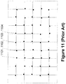
- An example of the image pattern is shown in Figure 11 .
- This pattern is used by the Anoto pen (by Anoto Inc.) to determine a location of a pen on a piece of paper.
- it is unclear how efficient the determination of the location is with the system used by the Anoto pen.
- To provide efficient determination of the location of the captured image a system is needed that provides an efficient extraction of bits from a captured image of the maze pattern.
- GUI graphical user interface
- PDGUIs Printed embedded data GUIs
- aspects of the present invention provide solutions to at least one of the issues mentioned above, thereby enabling one to extract bits from a maze pattern to locate a position or positions of the captured image on a viewed document.
- the viewed document may be on paper, LCD screen, or any other medium with the predefined pattern.
- aspects of the present invention include analyzing a document image and extracting bits of the associated m -array.
- the grid lines of a maze pattern are determined.
- the direction for each effective pixel of an associated bar is estimated.
- the estimated directions are grouped into clusters. Lines are estimated for selected effective pixels of a selected cluster that is associated with a first principal direction of the maze pattern.
- regression analysis is used to determine estimated lines.
- estimated lines are grouped based on slope variation analysis. A best fit line is selected from each group.
- grid lines of another cluster are determined, where the other cluster is associated with a second principal direction that is perpendicular or nearly perpendicular with the first principal direction.
- affine parameters are determined from grouped lines.
- Affine parameters may include horizontal and vertical rotations of the maze pattern, horizontal and vertical spacings of the grid lines, and horizontal and vertical offsets of the image center.
- grid lines are tuned to obtain a more refined approximation of the actual grid lines of the maze pattern.
- the correct orientation of a maze pattern is obtained by determining a type of missing corner of the maze pattern.
- a bit is extracted from the maze pattern by processing gray level values of the associated maze pattern cell.
- gray level values of neighboring maze pattern cells are further processed.
- aspects of the present invention relate to determining the location of a captured image in relation to a larger image.
- the location determination method and system described herein may be used in combination with a multi-function pen.
- the following is separated by subheadings for the benefit of the reader.
- the subheadings include: terms, general-purpose computer, image capturing pen, encoding of array, decoding, error correction, location determination, and maze pattern analysis.
- Pen - any writing implement that may or may not include the ability to store ink.
- a stylus with no ink capability may be used as a pen in accordance with embodiments of the present invention.
- Camera - an image capture system that may capture an image from paper or any other medium.
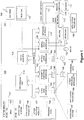
- Figure 1 is a functional block diagram of an example of a conventional general-purpose digital computing environment that can be used to implement various aspects of the present invention.
- a computer 100 includes a processing unit 110, a system memory 120, and a system bus 130 that couples various system components including the system memory to the processing unit 110.
- the system bus 130 may be any of several types of bus structures including a memory bus or memory controller, a peripheral bus, and a local bus using any of a variety of bus architectures.
- the system memory 120 includes read only memory (ROM) 140 and random access memory (RAM) 150.
- a basic input/output system 160 (BIOS), containing the basic routines that help to transfer information between elements within the computer 100, such as during start-up, is stored in the ROM 140.
- the computer 100 also includes a hard disk drive 170 for reading from and writing to a hard disk (not shown), a magnetic disk drive 180 for reading from or writing to a removable magnetic disk 190, and an optical disk drive 191 for reading from or writing to a removable optical disk 192 such as a CD ROM or other optical media.
- the hard disk drive 170, magnetic disk drive 180, and optical disk drive 191 are connected to the system bus 130 by a hard disk drive interface 192, a magnetic disk drive interface 193, and an optical disk drive interface 194, respectively.
- the drives and their associated computer-readable media provide nonvolatile storage of computer readable instructions, data structures, program modules and other data for the personal computer 100. It will be appreciated by those skilled in the art that other types of computer readable media that can store data that is accessible by a computer, such as magnetic cassettes, flash memory cards, digital video disks, Bernoulli cartridges, random access memories (RAMs), read only memories (ROMs), and the like, may also be used in the example operating environment.
- RAMs random access memories
- ROMs read only memories
- a number of program modules can be stored on the hard disk drive 170, magnetic disk 190, optical disk 192, ROM 140 or RAM 150, including an operating system 195, one or more application programs 196, other program modules 197, and program data 198.
- a user can enter commands and information into the computer 100 through input devices such as a keyboard 101 and pointing device 102.
- Other input devices may include a microphone, joystick, game pad, satellite dish, scanner or the like.
- These and other input devices are often connected to the processing unit 110 through a serial port interface 106 that is coupled to the system bus, but may be connected by other interfaces, such as a parallel port, game port or a universal serial bus (USB).
- USB universal serial bus
- these devices may be coupled directly to the system bus 130 via an appropriate interface (not shown).
- a monitor 107 or other type of display device is also connected to the system bus 130 via an interface, such as a video adapter 108.
- personal computers typically include other peripheral output devices (not shown), such as speakers and printers.
- a pen digitizer 165 and accompanying pen or stylus 166 are provided in order to digitally capture freehand input.
- the pen digitizer 165 may be coupled to the processing unit 110 directly, via a parallel port or other interface and the system bus 130 as known in the art.
- the digitizer 165 is shown apart from the monitor 107, it is preferred that the usable input area of the digitizer 165 be co-extensive with the display area of the monitor 107. Further still, the digitizer 165 may be integrated in the monitor 107, or may exist as a separate device overlaying or otherwise appended to the monitor 107.
- the computer 100 can operate in a networked environment using logical connections to one or more remote computers, such as a remote computer 109.
- the remote computer 109 can be a server, a router, a network PC, a peer device or other common network node, and typically includes many or all of the elements described above relative to the computer 100, although only a memory storage device 111 has been illustrated in Figure 1 .
- the logical connections depicted in Figure 1 include a local area network (LAN) 112 and a wide area network (WAN) 113.
- LAN local area network
- WAN wide area network
- the computer 100 When used in a LAN networking environment, the computer 100 is connected to the local network 112 through a network interface or adapter 114. When used in a WAN networking environment, the personal computer 100 typically includes a modem 115 or other means for establishing a communications over the wide area network 113, such as the Internet.
- the modem 115 which may be internal or external, is connected to the system bus 130 via the serial port interface 106.
- program modules depicted relative to the personal computer 100, or portions thereof, may be stored in the remote memory storage device.
- network connections shown are illustrative and other techniques for establishing a communications link between the computers can be used.
- the existence of any of various well-known protocols such as TCP/IP, Ethernet, FTP, HTTP, Bluetooth, IEEE 802.11x and the like is presumed, and the system can be operated in a client-server configuration to permit a user to retrieve web pages from a web-based server.
- Any of various conventional web browsers can be used to display and manipulate data on web pages.
- aspects of the present invention include placing an encoded data stream in a displayed form that represents the encoded data stream.
- the displayed form may be printed paper (or other physical medium) or may be a display projecting the encoded data stream in conjunction with another image or set of images.
- the encoded data stream may be represented as a physical graphical image on the paper or a graphical image overlying the displayed image (e.g., representing the text of a document) or may be a physical (non-modifiable) graphical image on a display screen (so any image portion captured by a pen is locatable on the display screen).
- the pen may be an ink pen writing on paper.
- the pen may be a stylus with the user writing on the surface of a computer display. Any interaction may be provided back to the system with knowledge of the encoded image on the document or supporting the document displayed on the computer screen.
- the displayed or printed image may be a watermark associated with the blank or content-rich paper or may be a watermark associated with a displayed image or a fixed coding overlying a screen or built into a screen.
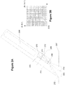
- FIGS 2A and 2B show an illustrative example of pen 201 with a camera 203.
- Pen 201 includes a tip 202 that may or may not include an ink reservoir.
- Camera 203 captures an image 204 from surface 207.
- Pen 201 may further include additional sensors and/or processors as represented in broken box 206. These sensors and/or processors 206 may also include the ability to transmit information to another pen 201 and/or a personal computer (for example, via Bluetooth or other wireless protocols).
- Figure 2B represents an image as viewed by camera 203.
- the field of view of camera 203 i.e., the resolution of the image sensor of the camera
- a captured image 32 pixels by 32 pixels
- Figure 2B shows a field of view of 32 pixels long by 32 pixels wide.
- the size of N is adjustable, such that a larger N corresponds to a higher image resolution.
- the field of view of the camera 203 is shown as a square for illustrative purposes here, the field of view may include other shapes as is known in the art.
- the images captured by camera 203 may be defined as a sequence of image frames ⁇ I i ⁇ where I i is captured by the pen 201 at sampling time t i .
- the sampling rate may be large or small, depending on system configuration and performance requirement.
- the size of the captured image frame may be large or small, depending on system configuration and performance requirement.
- the image captured by camera 203 may be used directly by the processing system or may undergo pre-filtering. This pre-filtering may occur in pen 201 or may occur outside of pen 201 (for example, in a personal computer).
- the image size of Figure 2B is 32x32 pixels. If each encoding unit size is 3x3 pixels, then the number of captured encoded units would be approximately 100 units. If the encoding unit size is 5x5 pixels, then the number of captured encoded units is approximately 36.
- Figure 2A also shows the image plane 209 on which an image 210 of the pattern from location 204 is formed.
- Light received from the pattern on the object plane 207 is focused by lens 208.
- Lens 208 may be a single lens or a multi-part lens system, but is represented here as a single lens for simplicity.
- Image capturing sensor 211 captures the image 210.
- the image sensor 211 may be large enough to capture the image 210.
- the image sensor 211 may be large enough to capture an image of the pen tip 202 at location 212.
- the image at location 212 is referred to as the virtual pen tip. It is noted that the virtual pen tip location with respect to image sensor 211 is fixed because of the constant relationship between the pen tip, the lens 208, and the image sensor 211.
- a location of the virtual pen tip L virtual-pentip may be determined.
- L virtual - pentip one can get a mote accurate estimation of L pentip .
- an accurate location of virtual pen tip L virtual - pentip may be determined.
- a two-dimensional array may be constructed by folding a one-dimensional sequence. Any portion of the two-dimensional array containing a large enough number of bits may be used to determine its location in the complete two-dimensional array. However, it may be necessary to determine the location from a captured image or a few captured images. So as to minimize the possibility of a captured image portion being associated with two or more locations in the two-dimensional array, a non-repeating sequence may be used to create the array.
- One property of a created sequence is that the sequence does not repeat over a length (or window) n . The following describes the creation of the one-dimensional sequence then the folding of the sequence into an array.
- a sequence of numbers may be used as the starting point of the encoding system.
- a sequence (also referred to as an m -sequence) may be represented as a q-element set in field F q .
- q p n where n ⁇ 1 and p is a prime number.
- the sequence or m -sequence may be generated by a variety of different techniques including, but not limited to, polynomial division. Using polynomial division, the sequence may be defined as follows: R l x P n x
- P n (x) is a primitive polynomial of degree n in field F q [x] (having q n elements).
- R l (x) is a nonzero polynomial of degree l (where l ⁇ n ) in field F q [x].
- the sequence may be created using an iterative procedure with two steps: first, dividing the two polynomials (resulting in an element of field F q ) and, second, multiplying the remainder by x. The computation stops when the output begins to repeat. This process may be implemented using a linear feedback shift register as set forth in an article by Douglas W.
- the array (or m -array) that may be used to create the image (of which a portion may be captured by the camera) is an extension of the one-dimensional sequence or m -sequence.
- n 1 ⁇ n 2 window shifts through a period of A, all the nonzero n 1 ⁇ n 2 matrices over F q appear once and only once.
- This property is also referred to as a "window property" in that each window is unique.
- a widow may then be expressed as an array of period ( m 1 , m 2 ) (with m 1 , and m 2 being the horizontal and vertical number of bits present in the array) and order (n 1 , n 2 ).
- a binary array may be constructed by folding the sequence.
- L 2 n - 1.
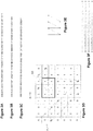
- Figures 3A through 3C show three different sequences. Each of these may be folded into the array shown as Figure 3D .
- the three different folding methods are shown as the overlay in Figure 3D and as the raster paths in Figures 3E and 3F .
- This folding approach may be alternatively expressed as laying the sequence on the diagonal of the array, then continuing from the opposite edge when an edge is reached.
- Figure 4A shows sample encoding techniques that may be used to encode the array of Figure 3D . It is appreciated that other encoding techniques may be used. For example, an alternative coding technique is shown in Figure 11 .
- a first bit 401 (for example, "1") is represented by a column of dark ink.
- a second bit 402 (for example, "0") is represented by a row of dark ink.
- any color ink may be used to represent the various bits. The only requirement in the color of the ink chosen is that it provides a significant contrast with the background of the medium to be differentiable by an image capture system.
- the bits in Figure 4A are represented by a 3x3 matrix of cells. The size of the matrix may be modified to be any size as based on the size and resolution of an image capture system.
- Alternative representation of bits 0 and 1 are shown in Figures 4C-4E .
- Figure 4C shows bit representations occupying two rows or columns in an interleaved arrangement.
- Figure 4D shows an alternative arrangement of the pixels in rows and columns in a dashed form.
- Figure 4E shows pixel representations in columns and rows in an irregular spacing format (e.g., two dark dots followed by a blank dot).
- more than one pixel or dot is used to represent a bit.
- Using a single pixel (or bit) to represent a bit is fragile. Dust, creases in paper, non-planar surfaces, and the like create difficulties in reading single bit representations of data units.
- different approaches may be used to graphically represent the array on a surface. Some approaches are shown in Figures 4C through 4E . It is appreciated that other approaches may be used as well.
- One approach is set forth in Figure 11 using only space-shifted dots.
- a bit stream is used to create the graphical pattern 403 of Figure 4B .
- Graphical pattern 403 includes 12 rows and 18 columns. The rows and columns are formed by a bit stream that is converted into a graphical representation using bit representations 401 and 402.
- Figure 4B may be viewed as having the following bit representation: 0 1 0 1 0 1 1 1 0 1 1 0 1 1 0 0 1 0 0 1 0 0 0 0 1 0 1 0 1 1 1 0 1 1 0 0 0 0 0 1 1 1 0 1 0 0 0 0
- pen 201 may utilize a pressure sensor as pen 201. is pressed against paper and pen 201 traverses a document on the paper. The image is then processed to determine the orientation of the captured image with respect to the complete representation of the encoded image and extract the bits that make up the captured image.
- the image captured by a camera 601 may be analyzed and its orientation determined so as to be interpretable as to the position actually represented by the image 601.
- image 601 is reviewed to determine the angle ⁇ needed to rotate the image so that the pixels are horizontally and vertically aligned.
- alternative grid alignments are possible including a rotation of the underlying grid to a non-horizontal and vertical arrangement (for example, 45 degrees).
- Using a non-horizontal and vertical arrangement may provide the probable benefit of eliminating visual distractions from the user, as users may tend to notice horizontal and vertical patterns before others.
- the orientation of the grid (horizontal and vertical and any other rotation of the underlying grid) is referred to collectively as the predefined grid orientation.
- image 601 is analyzed to determine which corner is missing.
- the rotation amount is shown by the equation in Figure 7 .
- angle ⁇ is first determined by the layout of the pixels to arrive at a horizontal and vertical (or other predefined grid orientation) arrangement of the pixels and the image is rotated as shown in 602.
- An analysis is then conducted to determine the missing corner and the image 602 rotated to the image 603 to set up the image for decoding.
- the image is rotated 90 degrees counterclockwise so that image 603 has the correct orientation and can be used for decoding.
- rotation angle ⁇ may be applied before or after rotation of the image 601 to account for the missing corner. It is also appreciated that by considering noise in the captured image, all four types of corners may be present. We may count the number of corners of each type and choose the type that has the least number as the corner type that is missing.
- the code in image 603 is read out and correlated with the original bit stream used to create image 403.
- the correlation may be performed in a number of ways. For example, it may be performed by a recursive approach in which a recovered bit stream is compared against all other bit stream fragments within the original bit stream. Second, a statistical analysis may be performed between the recovered bit stream and the original bit stream, for example, by using a Hamming distance between the two bit streams. It is appreciated that a variety of approaches may be used to determine the location of the recovered bit stream within the original bit stream.
- maze pattern analysis obtains recovered bits from image 603. Once one has the recovered bits, one needs to locate the captured image within the original array (for example, the one shown in Figure 4B ).
- the process of determining the location of a segment of bits within the entire array is complicated by a number of items.
- the actual bits to be captured may be obscured (for example, the camera may capture an image with handwriting that obscures the original code).
- Second, dust, creases, reflections, and the like may also create errors in the captured image. These errors make the localization process more difficult.
- the image capture system may need to function with non-sequential bits extracted from the image. The following represents a method for operating with non-sequential bits from the image.
- the location s of the K bits is just the number of cyclic shifts of I so that b 0 is shifted to the beginning of the sequence.
- the solution of r may be expressed as: where M ⁇ is any non-degenerate n ⁇ n sub-matrix of M and b ⁇ is the corresponding sub-vector of b.
- the Hamming distance between and or the number of error bits associated with r should be minimal, where r is computed via equation (4). Repeating the process for several times, it is likely that the correct r that results in the minimal error bits can be identified.
- the system then may move on to process the next captured image.
- information about previous locations of the pen can be taken into consideration. That is, for each captured image, a destination area where the pen may be expected next can be identified. For example, if the user has not lifted the pen between two image captures by the camera, the location of the pen as determined by the second image capture should not be too far away from the first location.
- Each r that is associated with the minimum number of error bits can then be checked to see if the location s computed from r satisfies the local constraint, i.e., whether the location is within the destination area specified.
- the decoding process fails.
- Figure 8 depicts a process that may be used to determine a location in a sequence (or m- sequence) of a captured image.
- a data stream relating to a captured image is received.
- corresponding columns are extracted from A and a matrix M is constructed.
- step 803 n independent column vectors are randomly selected from the matrix M and vector r is determined by solving equation (4). This process is performed Q times (for example, 100 times) in step 804. The determination of the number of loop times is discussed in the section Loop Times Calculation.
- r is sorted according to its associated number of error bits.
- the sorting can be done using a variety of sorting algorithms as known in the art. For example, a selection sorting algorithm may be used. The selection sorting algorithm is beneficial when the number Q is not large. However, if Q becomes large, other sorting algorithms (for example, a merge sort) that handle larger numbers of items more efficiently may be used.
- step 806 determines in step 806 whether error correction was performed successfully, by checking whether multiple r's are associated with the minimum number of error bits. If yes, an error is returned in step 809, indicating the decoding process failed. If not, the position s of the extracted bits in the sequence (or m -sequence) is calculated in step 807, for example, by using the Pohig-Hellman-Silver algorithm.
- Figure 9 shows a process for determining the location of a pen tip.
- the input is an image captured by a camera and the output may be a position coordinates of the pen tip. Also, the output may include (or not) other information such as a rotation angle of the captured image.
- step 901 an image is received from a camera.
- the received image may be optionally preprocessed in step 902 (as shown by the broken outline of step 902) to adjust the contrast between the light and dark pixels and the like.
- step 903 the image is analyzed to determine the bit stream within it.
- n bits are randomly selected from the bit stream for multiple times and the location of the received bit stream within the original sequence (or m -sequence) is determined.
- step 904 the location of the pen tip may be determined in step 905.
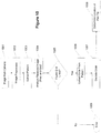
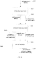
- Figure 10 gives more details about 903 and 904 and shows the approach to extract the bit stream within a captured image.
- an image is received from the camera in step 1001.
- the image then may optionally undergo image preprocessing in step 1002 (as shown by the broken outline of step 1002).
- the pattern is extracted in step 1003.
- pixels on the various lines may be extracted to find the orientation of the pattern and the angle ⁇ .
- step 1004 the received image is analyzed in step 1004 to determine the underlying grid lines. If grid lines are found in step 1005, then the code is extracted from the pattern in step 1006. The code is then decoded in step 1007 and the location of the pen tip is determined in step 1008. If no grid lines were found in step 1005, then an error is returned in step 1009.
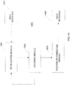
- FIG. 12 shows a flow diagram of process 1200 of this enhanced approach.
- Process 1200 comprises two components 1251 and 1253.
- the embodiment of the invention utilizes a discreet strategy to select bits, adjusts the number of loop iterations, and determines the X,Y position (location coordinates) in accordance with a local constraint, which is provided to process 1200.
- steps 1205 and 1219 (“Decode Once") utilize equation (4) to compute r.
- the difference between b and b ⁇ are the error bits associated with r.
- FIG. 12 shows a flow diagram of process 1200 for decoding extracted bits 1201 from a captured image in accordance with embodiments of the present invention.
- Process 1200 comprises components 1251 and 1253.
- Component 1251 obtains extracted bits 1201 (comprising K bits) associated with a captured image (corresponding to a captured array).
- n bits (where n is the order of the m -array) are randomly selected from extracted bits 1201.
- process 1200 decodes once and calculates r.
- process 1200 determines if error bits are detected for b. If step 1207 determines that there are no error bits, X,Y coordinates of the position of the captured array are determined in step 1209.
- step 1211 if the X,Y coordinates satisfy the local constraint, i.e., coordinates that are within the destination area, process 1200 provides the X,Y position (such as to another process or user interface) in step 1213. Otherwise, step 1215 provides a failure indication.
- step 1207 detects error bits in b
- component 1253 is executed in order to decode with error bits.
- Step 1217 selects another set of n bits (which differ by at least one bit from the n bits selected in step 1203) from extracted bits 1201.
- Steps 1221 and 1223 determine the number of iterations (loop times) that are necessary for decoding the extracted bits.
- Step 1225 determines the position of the captured array by testing which candidates obtained in step 1219 satisfy the local constraint. Steps 1217-1225 will be discussed in more details.
- Step 1203 randomly selects n bits from extracted bits 1201 (having K bits), and solves for r 1 .
- decoded bits can be calculated.
- I 1 ⁇ k ⁇ ⁇ 1,2, ⁇ , K ⁇
- b k ⁇ b ⁇ k ⁇ , where b ⁇ k is the k th bit of b ⁇ , B 1 ⁇ b k
- k ⁇ I 1 ⁇ and B ⁇ 1 ⁇ b k
- step 1217 selects the next n bits according to the following procedure:
- the error correction component 1253 With the error correction component 1253, the number of required iterations (loop times) is adjusted after each loop. The loop times is determined by the expected error rate.
- Adjusting the loop times may significantly reduce the number of iterations of process 1253 that are required for error correction.
- the decoded position should be within the destination area.
- the destination area is an input to the algorithm, and it may be of various sizes and places or simply the whole m -array depending on different applications. Usually it can be predicted by the application. For example, if the previous position is determined, considering the writing speed, the destination area of the current pen tip should be close to the previous position. However, if the pen is lifted, then its next position can be anywhere. Therefore, in this case, the destination area should be the whole m -array.
- the correct X,Y position is determined by the following steps.
- Step 1224 sorts r i in ascending order of the number of error bits. Steps 1225, 1211 and 1212 then finds the first r i in which the corresponding X,Y position is within the destination area. Steps 1225, 1211 and 1212 finally returns the X,Y position as the result (through step 1213), or an indication that the decoding procedure failed (through step 1215).
- An illustrative example demonstrates process 1200 as performed by components 1251 and 1253.
- A I 0 I 1 I 2 I 3 I 4 I 5 I 6 I 6 I 0 I 1 I 2 I 3 I 4 I 5 I 5 I 6 I 0 I 1 I 2 I 3 I 4
- M I 0 I 1 I 3 I 4 I 6 I 6 I 0 I 2 I 3 I 5 I 5 I 6 I 1 I 2 I 4 which consists of the 0 th , 1 st , 3 rd , 4 th , and 6 th columns of A.
- step 1209 determines the X,Y position and step 1211 determines whether the decoded position is inside the destination area. If so, the decoding is successful, and step 1213 is performed. Otherwise, the decoding fails as indicated by step 1215. If b ⁇ 1 , is different from b, then error bits in b are detected and component 1253 is performed.
- Step 1217 determines the set B 1 , say ⁇ b 0 b 1 b 2 b 3 ⁇ , where the decoded bits are the same as the original bits.
- B ⁇ 1 ⁇ b 4 ⁇ (corresponding to bit arrangement 1351 in Figure 13 ).
- Loop times ( lt ) is initialized to a constant, e.g., 100, which may be variable depending on the application. Note that the number of error bits corresponding to r 1 is equal to 1.
- B 2 e.g., ⁇ b 0 b 1 b 4 ⁇ , such that b ⁇ 2 and b are the same.
- B ⁇ 2 ⁇ b 2 b 3 ⁇ (corresponding to bit arrangement 1353 in Figure 13 ).
- the selected bits shall not all belong to either B 1 or B 2 . So step 1217 may select, for example, one bit ⁇ b 4 ⁇ from B ⁇ 1 , one bit ⁇ b 2 ⁇ from B ⁇ 2 , and the remaining one bit ⁇ b 0 ⁇ .
- Step 1224 selects r i 's, for example, r 1, r 2 ,r 4 ,r 5 , whose corresponding numbers of error bits are less than N e shown in (8).
- Step 1224 sorts the selected vectors r 1, r 2 ,r 4 ,r 5 in ascending order of their error bit numbers: r 1 ,r 2 ,r 5 ,r 4 . From the sorted candidate list, steps 1225, 1211 and 1212 find the first vector r , for example, r 5 , whose corresponding position is within the destination area. Step 1213 then outputs the corresponding position. If none of the positions is within the destination area, the decoding process fails as indicated by step 1215.
- Figure 14 shows an apparatus 1400 for decoding extracted bits 1201 from a captured array in accordance with embodiments of the present invention.
- Apparatus 1400 comprises bit selection module 1401, decoding module 1403, position determination module 1405, input interface 1407, and output interface 1409.
- interface 1407 may receive extracted bits 1201 from different sources, including a module that supports camera 203 (as shown in Figure 2A ).
- Bit selection module 1401 selects n bits from extracted bits 1201 in accordance with steps 1203 and 1217.
- Decoding module 1403 decodes the selected bits ( n bits selected from the K extracted bits as selected by bit selection module 1401) to determine detected bit errors and corresponding vectors r i in accordance with steps 1205 and 1219.
- Decoding module 1403 presents the determined vectors r i to position determination module 1405.
- Position determination module 1405 determines the X,Y coordinates of the captured array in accordance with steps 1209 and 1225.
- Position determination module 1405 presents the results, which includes the X,Y coordinates if successful and an error indication if not successful, to output interface 1409.
- Output interface 1409 may present the results to another module that may perform further processing or that may display the results.
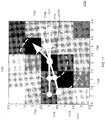
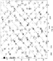
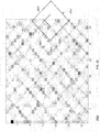
- FIG 15 shows an exemplary image of a maze pattern 1500 that illustrates maze pattern cell 1501 with an associated maze pattern bar 1503 in accordance with embodiments of the invention.
- Maze pattern 1500 contains maze pattern bars, e.g., 1503.
- Effective pixels (EPs) are pixels that are most likely to be located on the maze pattern bars as shown in Figure 15 .
- Figure 15 shows separated effective pixels of an example image corresponding to maze pattern 1500. If document content is captured, then the number of effective pixels is estimated as (32*32-n) ⁇ (1/3.2), where n is the number of pixels which lie on document content area.
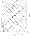
- Figure 16 shows an exemplary image of maze pattern 1600 that illustrates estimated directions for the effective pixels in accordance with embodiments of the invention.
- an estimated direction e.g., estimated directions 1601 or 1603
- a histogram of all estimated directions is formed. From the histogram, two directions that are about 90 degrees apart (for example, they may be 80, 90 or 100 degrees apart) and occurred the most often (sum of their frequencies is the maximum among all pairs of directions that are 80, 90, or 100 degrees apart) are chosen as the initial centers of two clusters of estimated directions. All effective pixels are clustered into the two clusters based on whether their estimated directions are closer to the center of the first cluster or to the center of the second cluster.
- the distance between the estimated direction and a center can be expressed as min(180 -
- x is the estimated direction of an effective pixel and center is the center of a cluster.
- Direction 1605 and direction 1607 correspond to the two principal directions of the grid lines.
- Figure 17 shows an exemplary image of a portion of maze pattern 1700 that illustrates estimating a direction for an effective pixel in accordance with embodiments of the invention.
- an effective pixel e.g., effective pixel 1701
- the direction 1723 with lowest mean gray level value is selected as the estimated direction of effective pixel 1701. In other embodiments, the sampling angle interval may be less than 10 degrees to obtain a more precise estimate of the direction.
- the length of radius PA + 0 1705 and radius PB + 0 1703 are selected as 1 pixel and 2 pixels, respectively.
- the x, y value of position of points used to estimate the direction may not be an integer, e.g., points A + 1 , B + 1 , A - 1 , and B - t .
- the gray level values of corresponding points may be obtained by bilinear sampling the gray level values of neighbor pixels.
- G x , y 1 ⁇ y d ⁇ [ 1 ⁇ x d ⁇ G x 1 , y 1 + x d ⁇ G x 1 + 1, y 1 + y d ⁇ 1 ⁇ x d ⁇ G x 1 , y 1 + 1 + x d ⁇ G x 1 + 1, y 1 + 1
- x 1 ,y 1 and x d ,y d are the integer parts and the decimal fraction parts of x, y, respectively.
- Figure 18 shows an exemplary image of maze pattern 1800 that illustrates calculating line parameters for a grid line that passes through representative effective pixel 1809 in accordance with embodiments of the invention.
- One selects a cluster with more effective pixels and computes the line parameters in this direction because there is typically a larger error when estimating the principal direction with less effective pixels.
- By calculating the line parameters in the direction with more effective pixels a more precise estimate of the principal direction with less effective pixels is obtained by using a perpendicular constraint of two directions.
- grid lines are associated with two nearly orthogonal sets of grid lines.
- the approach is typically effective in a maze pattern with a text area.
- a sector of interest area is determined based on the principal direction.
- the sector of interest is determined by vector 1805 and 1807, in which the angle between each vector and the principle direction 1801 is less than a constant angle, e.g., 10 degrees.
- a constant angle e.g. 10 degrees.
- Step 1 All effective pixels which are in the cluster, and located in the sector of interest of effective pixel 1809, are incorporated to calculate the line parameters by using a least squares regression algorithm.
- Step 2 The distance between each effective pixel used in regressing the line and the estimated line is calculated. If all these distances are less than a constant value, e.g. 0.5 pixels, the estimated line parameters are sufficiently good, and the regression process ends. Otherwise, the standard deviation of the distances is calculated.
- a constant value e.g. 0.5 pixels
- Step 3 Effective pixels used in regressing the line whose distance to the estimated line is less than the standard deviation multiplied by a constant (for example 1.2) are chosen to estimate the line parameters again to obtain another estimate of the line parameters.
- a constant for example 1.2
- Step 4 The estimated line parameters are compared with the estimated parameters from the last iteration. If the difference is sufficiently small, i.e.,
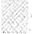
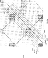
- Figure 19 shows all regressed lines of one example image in a first principal direction. Consequently, there exist error lines as illustrated in Figure 19 . In the subsequent stage of processing, estimated lines are pruned and used to obtain affine parameters of grids.
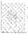
- Figure 21 shows an exemplary image of maze pattern 2100 that illustrates pruning estimated grid lines for a first principal direction in accordance with embodiments of the invention.
- the mean slope value ⁇ and the standard deviation ⁇ of all lines are calculated. If ⁇ ⁇ 0.05, lines are regarded as parallel and no pruning is needed. Otherwise, each line that has a slope k that differs significantly from the mean slope value ⁇ are pruned, namely if
- a line that passes the image center and is perpendicular to the mean slope of the lines is obtained.
- the intersection points between regressed lines and the perpendicular line are calculated. All intersection points are clustered with the condition that the center of any two clusters should be larger than a constant.
- the constant is the possible smallest scale of grid lines.
- the example shown in Figure 21 has six groupings of lines: 2101, 2103, 2105, 2107, 2109, and 2111.
- Figure 22 shows an exemplary image of maze pattern 2200 in which best fit lines (e.g., line 2201) are selected from the pruned grid lines in accordance with embodiments of the invention.
- the best fit line corresponds to a line having a regression error (obtained in the robust regression step) that is smaller than the other lines in the same group of lines.
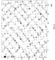
- Figure 20 shows an exemplary image of maze pattern 2000 that illustrates estimated grid lines associated with the remaining cluster in accordance with embodiments of the invention.
- grid lines are estimated using a perpendicular constraint for the remaining cluster, i.e., the direction that is perpendicular to the final estimate of the direction of the first cluster is used as the initial direction during line regression.
- the process is the same as illustrated in Figures 18-22 for the first principle direction.
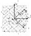
- Figure 23 shows an exemplary image of maze pattern 2300 with associated affine parameters in accordance with embodiments of the invention.
- the scale is obtained by averaging the distance of adjacent best fit lines as shown in Figure 22 .
- the distance between two adjacent lines in Figure 22 may be two or more times of the real scale. (For example, line 2203 and line 2205 may be two or more times of the real scale.) In other words, there is a line between 2203 and 2205 whose parameters are not obtained.
- a prior knowledge about the range of possible scales (given the size of the image sensor, size of maze pattern printed on paper, etc.) is used to estimate how many times a distance should be divided.
- the distance between line 2203 and 2205 is divided by 2 and then averaged with other distances.
- the offset is obtained from the distance between the image center and the nearest line to the image center. (The offset may be needed to obtain grid lines on which points are sampled to extract bits.) Assuming that the grid lines are evenly spaced and that grid lines are parallel, a group of affine parameters may be used to describe the grid lines.
- the result of maze pattern analysis as shown in Figure 23 includes the scale (S y 2301 and S x 2303), the rotation of the grid lines in two directions ⁇ x 2305 and ⁇ y 2307, and the nearest distance between grid lines in 2 directions (d y 2311 and d x 2309).
- Figure 24 shows an exemplary image of maze pattern 2400 that illustrates tuning a grid line in accordance with embodiments of the invention.
- a line that is parallel and near each obtained grid line L 2401 may be found, in which the line better approximates the actual grid line.
- scale is the grid scale (S x ).
- the selection of P k,i is shown in Figure 24 .
- P k,i are selected starting from one border of the image in equal distances, which may be a constant, for example, 1/3 of the scale of the direction of the line (s y ). In the embodiment, a smaller gray level value corresponds to a darker image element. However, other embodiments of the invention may associate a larger gray level value with a darker image element. (The "arg" function denotes that k optimal has a minimum gray level sum that corresponds to one of the lines having an index between -d and d.)
- Figure 25 shows an exemplary image of a maze pattern with grid lines after tuning in accordance with embodiments of the invention.
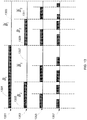
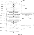
- Figure 26 shows process 2600 for determining grid lines for a maze pattern in accordance with embodiments of the invention.
- Process 2600 incorporates the processing as previously discussed.
- Process 2600 can be grouped into sub-processes 2651, 2653, 2655, and 2657.
- Sub-process 2651 includes step 2601, in which effective pixels are separated for an image of a maze pattern.
- sub-process 2653 lines are estimated for representative effective pixels.
- Sub-process 2653 comprises steps 2603-2611 and 2625.
- step 2603 the direction of the maze pattern bar is estimated for each effective pixel.
- step 2605 the estimated directions are grouped into two clusters.
- step 2607 the cluster with the greater number of effective pixels is selected and the principal direction is estimated from the directions of the effective pixels that are associated with the selected cluster in step 2609.
- step 2611 lines are estimated through selected effective pixels with regression techniques.
- Sub-process 2655 affine parameters of the grid lines are determined.
- Sub-process 2655 includes steps 2613-2621.
- the lines are pruned in step 2613 by slope variance analysis and the pruned lines are grouped by the projection distance in step 2615.
- the best fit line is selected in each group in step 2617.
- step 2619 determines that the remaining cluster has not been processed, the remaining cluster is selected in step 2627.
- the associated grid lines are estimated using a perpendicular constraint in step 2625. Consequently, steps 2611-2617 are repeated.
- step 2621 affine parameters are determined from the grouped lines.
- sub-process 2657 the grid lines are tuned in step 2623 as discussed with Figure 24 .
- Figure 27 shows an exemplary image of a maze pattern that illustrates determining a correct orientation of the maze pattern in accordance with embodiments of the invention.
- the correct orientation of the maze pattern has to be determined.
- the algorithm has three stages. As shown in Figure 27 , grid edges are separated into two groups, i.e., X and Y edges that are parallel with H axis and V axis respectively, and with corresponding scores are represented as ScoreX and ScoreY. Scores are calculated by bilinear sampling algorithm.
- the sampling point on each edge to calculate the score corresponds to the middle point of the edge.
- ScoreY is calculated by the same bilinear sampling algorithm as ScoreX except for using a different sampling point in the image as the bilinear input
- maze pattern cell 2709 is associated with corners 2701, 2703, 2705, and 2707.
- corners 2701, 2703, 2705, and 2707 correspond to corner 0, corner 1, corner 2, and corner 3, respectively.
- the associated number of a corner is referred to as the quadrant number as will be discussed.
- n i and n j are the total count of grid cells within the image in H axis and V axis direction respectively.
- N 0 is the number of grid cells in which both ScoreX(i, j) and ScoreY(i, j) are valid. (The validity of ScoreX(i,j) and ScoreY(i,j) is determined by bilinear sampling shown in Equation 19.)
- n i and n j are the total count of grids within the image in H axis and V axis direction respectively
- N 1 is the number of grid cells in which both ScoreX(i, j) and ScoreY(i+1,j) are valid.
- n i and n j are the total count of grids within the image in H axis and V axis direction respectively
- N 2 is the number of grid cells in which both ScoreX(i,j+1) and ScoreY(i+1,j) are valid.
- n i and n j are the total count of grids within the image in H axis and V axis direction respectively
- N 3 is the number of grid cells in which both ScoreX(i,j+1) and ScoreY(i, j) are valid.
- the correct orientation is i if Q [ i ] is maximum of Q, where i is the quadrant number.
- ScoreX and ScoreY are also rotated for the next stage of extracting bits from the maze pattern.
- maze pattern cells in captured images fall into two categories: completely visible cells and partially visible cells. Completely visible cells are maze pattern cells in which both ScoreX and ScoreY are valid. Partially visible cells are the maze pattern cells in which only one score of ScoreX and ScoreY is valid.
- Figure 28 shows an exemplary image of maze pattern 2800 in which a bit is extracted from partially visible maze pattern cell 2801 in accordance with embodiments of the invention.
- a partially visible maze pattern cell may occur at an edge of an image or in an area of an image where text or drawings obscure the maze pattern.
- a partially visible bits extraction algorithm is based on completely visible cells (corresponding to maze pattern cells 2803, 2805, and 2807) in the 8-neighbor cells of partially visible cell 2801.
- For extracting a bit from a cell that is partially visible e.g. maze pattern cell 2801), one may compare score values of the partially visible maze pattern cell with a function of mean scores along edges of neighboring maze pattern cells (e.g., maze pattern cells 2803, 2805, and 2807).
- Score ( i,j ) is the valid score of ScoreX ( i,j ) or ScoreY ( i,j )
- MaxDiff is a maximum score difference of all complete visible bits.
- extracted bits 1201 are decoded, and error correction is performed if needed.
- selected bits that have a confidence level greater than a predetermined level are used for error correction if the number of selected bits is sufficiently large.
- the extracted bits are rank ordered in accordance with associated confidence levels. Decoding of the extracted bits utilizes extracted bits according to the rank ordering.
- the degree of confidence associated with an extracted bit may be utilized when correcting for bit errors. For example, bits having a lowest degree of confidence are not processed when performing error correction.
- Figure 29 shows apparatus 2900 for extracting bits from a maze pattern in accordance with embodiments of the invention.
- Normalized image 2951 is first processed by grid lines analyzer 2901 in order to determine the grid lines of the image.
- grid line analyzer 2901 performs process 2600 as shown in Figure 26 .
- Grid line analyzer 2901 determines grid line parameters 2953 (e.g., S x , S y , ⁇ x , ⁇ y , d x , d y as shown in Figure 23 ).
- Orientation analyzer 2903 further processes normalized image 2951 using grid line parameters 2953 to determine correct orientation information 2955 of the maze pattern.
- Bit extractor 2905 processes normalized image 2951 using grid line parameters 2953 and correct orientation information 2955 to extract bit stream 2957.
- apparatus 2900 may incorporate an image normalizer (not shown) that reduces the effect of non-uniform illumination of the image.
- Non-uniform illumination may cause some pattern bars not to be as dark as they should be and some non-bar areas to be darker than they should be, which may affect the estimate of the direction of effective pixels and may result in error bits being extracted.
- Apparatuses 1400 and 2900 may assume different forms of implementation, including modules utilizing computer-readable media and modules utilizing specialized hardware such as an application specific integrated circuit (ASIC).
- ASIC application specific integrated circuit
- the computer system may include at least one computer such as a microprocessor, digital signal processor, and associated peripheral electronic circuitry.
Landscapes
- Engineering & Computer Science (AREA)
- Theoretical Computer Science (AREA)
- General Engineering & Computer Science (AREA)
- Physics & Mathematics (AREA)
- General Physics & Mathematics (AREA)
- Human Computer Interaction (AREA)
- Multimedia (AREA)
- Signal Processing (AREA)
- Computer Vision & Pattern Recognition (AREA)
- Image Processing (AREA)
- Image Analysis (AREA)
Claims (41)
- Procédé implémenté par ordinateur pour analyser une image capturée (601) ayant un motif de labyrinthe (1500) et un contenu de document et pour déterminer des bits associés d'une matrice-m (A) ayant une propriété de fenêtre, la matrice-m étant construite en pliant un séquence-m unidimensionnelle, à partir d'une représentation de document, la représentation de document étant filigranée par le motif de labyrinthe, le motif de labyrinthe étant obtenu en codant la matrice-m à l'aide de représentations binaires de couleurs contrastées, comprenant des pixels le long de rangées et de colonnes, formant un motif graphique comprenant des coins, avec une orientation de grille prédéfinie, le procédé comprenant de :(A) détecter (1005) une pluralité de lignes de grille (2401) pour le motif de labyrinthe à partir d'une pluralité de pixels effectifs (1701) et aligner le motif de labyrinthe, sur la base des lignes de grille détectées, sur l'orientation de grille prédéfinie ;(B) déterminer un type de coin manquant (5A - 5D) à partir du motif de labyrinthe aligné pour corriger l'orientation du motif de labyrinthe en faisant tourner le motif de labyrinthe, déterminer une orientation correcte (603) du motif de labyrinthe (1500) sur la base du type déterminé de coin manquant (5A - 5D), et faire tourner le motif de labyrinthe (602) en fonction du type déterminé de coin manquant (5A - 5D) ; et(C) extraire une pluralité de bits (1201) du motif de labyrinthe en traitant le motif de labyrinthe le long des lignes de grille détectées, la pluralité de bits contenant des informations de matrice-m associées lorsque codées par les représentations binaires.
- Procédé selon la revendication 1, comprenant en outre de :(D) déterminer un niveau de confiance qui est associé à un bit (401) du motif de labyrinthe (1500).
- Procédé selon la revendication 2, comprenant en outre de :(E) sélectionner (1224) un sous-ensemble parmi la pluralité de bits (1201), chaque bit du sous-ensemble ayant un niveau de confiance associé qui est supérieur à un niveau prédéterminé.
- Procédé selon la revendication 3, comprenant en outre de :(F) décoder une position (1225) dans la matrice-m à partir du sous-ensemble de bits (1224).
- Procédé selon la revendication 1, dans lequel la détection (1005) d'une pluralité de lignes de grille (2401) comprend en outre de :(i) séparer des pixels effectifs (1701) dans l'image capturée (601) du motif de labyrinthe (1500).
- Procédé selon la revendication 5, dans lequel la détection (1005) d'une pluralité de lignes de grille (2401) comprend en outre de :(ii) estimer une ligne estimée (1803) pour chaque pixel effectif séparé (1809).
- Procédé selon la revendication 6, dans lequel la détection (1005) d'une pluralité de lignes de grille (2401) comprend en outre de :(iii) déterminer (2611) des paramètres de ligne de grille pour la pluralité de lignes de grille (2401).
- Procédé selon la revendication 7, dans lequel la détection (1005) d'une pluralité de lignes de grille (2401) comprend en outre de :(iv) accorder (2623) la pluralité de lignes de grille (2401).
- Procédé selon la revendication 6, dans lequel l'estimation d'une ligne estimée comprend en outre de :(1) estimer (2603) une pluralité de directions, chaque direction correspondant à une barre de motif de labyrinthe (1503) traversant un pixel effectif (1701).
- Procédé selon la revendication 9, dans lequel l'estimation d'une ligne estimée comprend en outre de :(2) former (2605) deux groupes à partir de la pluralité de directions.
- Procédé selon la revendication 10, comprenant en outre de :(3) déterminer une direction estimée initiale pour chacun des deux groupes à partir d'un histogramme de toutes les directions estimées (2603).
- Procédé selon la revendication 10, dans lequel l'estimation d'une ligne estimée comprend en outre de :(3) sélectionner (2607) un premier des deux groupes qui est associé à un nombre plus grand de pixels effectifs.
- Procédé selon la revendication 12, dans lequel l'estimation d'une ligne estimée comprend en outre de :(4) estimer (2609) une direction principale à partir de directions associées dudit premier groupe.
- Procédé selon la revendication 13, dans lequel l'estimation d'une ligne estimée comprend en outre de :(5) déterminer (2611) un ensemble de paramètres de ligne correspondant pour chaque pixel effectif choisi (1701), chaque ensemble de paramètres de ligne correspondant correspondant à une ligne qui régresse.
- Procédé selon la revendication 14, dans lequel la détermination (2611) d'un ensemble de paramètres de ligne correspondant comprend l'exécution d'une analyse de régression pour une pluralité correspondante de pixels effectifs associés à chacun desdits pixels effectifs choisis (1701).
- Procédé selon la revendication 15, dans lequel l'estimation d'une ligne estimée comprend en outre de :(6) utiliser (2625) une contrainte perpendiculaire pour estimer une direction de ligne de grille d'un autre groupe.
- Procédé selon la revendication 7, dans lequel la détermination (2611) de paramètres de ligne de grille comprend en outre de :(1) réduire (2613) une pluralité de lignes qui régressent pour former un ensemble de lignes réduit.
- Procédé selon la revendication 17, dans lequel la réduction utilise une analyse de variance de pente.
- Procédé selon la revendication 17, dans lequel la détermination (2611) de paramètres de ligne de grille comprend en outre de :(2) regrouper (2615) l'ensemble de lignes réduit pour former une pluralité de groupes de lignes.
- Procédé selon la revendication 19, dans lequel le regroupement de l'ensemble réduit utilise des distances de projection associées entre des groupes de lignes adjacents.
- Procédé selon la revendication 19, dans lequel la détermination (2611) de paramètres de ligne de grille comprend en outre de :(3) sélectionner (2617) une ligne à meilleur ajustement (2201) pour chaque groupe de la pluralité de groupes de lignes.
- Procédé selon la revendication 21, dans lequel la détermination (2611) de paramètres de ligne de grille comprend en outre de :(4) déterminer (2621) au moins un paramètre affine à partir d'une pluralité de lignes à meilleur ajustement (2201).
- Procédé selon la revendication 22, dans lequel le au moins un paramètre affine est choisi parmi le groupe constitué d'une échelle horizontale (Sx), d'une échelle verticale (Sy), d'un décalage horizontal (dx), d'un décalage vertical (dy), d'une rotation horizontale (x) et d'une rotation verticale (Y).
- Procédé selon la revendication 8, dans lequel l'accord (2623) de la pluralité de lignes de grille comprend de :(1) déterminer au moins une première ligne (2403 - 2417) suffisamment proche d'une ligne à meilleur ajustement sélectionnée (2201), la au moins une ligne étant approximativement parallèle à la ligne à meilleur ajustement sélectionnée et à une distance prédéterminée de la ligne à meilleur ajustement.
- Procédé selon la revendication 24, dans lequel l'accord (2623) de la pluralité de lignes de grille comprend en outre de :(2) sélectionner une ligne parmi la au moins première ligne (2403 - 2417) et la ligne à meilleur ajustement (2201), la première ligne ayant une caractéristique la plus sombre.
- Procédé selon la revendication 24, dans lequel l'accord (2623) de la pluralité de lignes de grille comprend en outre de :(2) sélectionner une ligne parmi la au moins première ligne (2403 - 2417) et la ligne à meilleur ajustement (2201), laquelle ligne ayant une somme de niveaux de gris la plus petite.
- Procédé selon la revendication 1, dans lequel la détermination d'un type de coin manquant comprend de :(1) déterminer une différence de scores moyenne de chaque type de coin (5A - 5D) ; et(2) sélectionner le type de coin manquant correspondant à une différence de scores moyenne maximale.
- Procédé selon la revendication 27, dans lequel une valeur de score est basée sur un échantillonnage bilinéaire.
- Procédé selon la revendication 1, dans lequel l'extraction d'une pluralité de bits (1201) comprend de :(i) si une cellule de motif de labyrinthe (1501) est complètement visible, effectuer une comparaison de valeur de niveau de gris d'un score horizontal (ScoreX()) avec un score vertical (ScoreY()) pour extraire un bit correspondant ; et(ii) si la cellule de motif de labyrinthe est partiellement visible (2801), comparer une fonction de scores moyens de bord avec le score horizontal et le score vertical, les scores moyens de bord correspondant à des cellules voisines de motif de labyrinthe qui sont complètement visibles.
- Procédé selon la revendication 29, dans lequel la réalisation d'une comparaison de valeurs de niveau de gris (i) comprend de :(1) si le score horizontal est inférieur au score vertical, établir le bit correspondant à « 0 »;(2) si le score horizontal est supérieur au score vertical, établir le bit correspondant à « 1 » ; et(3) si le score horizontal est égal au score vertical, invalider le bit correspondant.
- Procédé selon la revendication 29, dans lequel la fonction est égale à une moyenne d'un score moyen de bord noir de référence (BMS) et d'un score moyen de bord blanc de référence (WMS) des cellules voisines de motif de labyrinthe (1501) qui sont complètement visibles.
- Procédé selon la revendication 2, dans lequel la détermination d'un niveau de confiance comprend de :(i) établir le niveau de confiance à une fonction d'un score horizontal (Score(X()) et d'un score vertical (Score(Y()).
- Procédé selon la revendication 32, dans lequel la fonction est proportionnelle à une valeur absolue d'une différence du score horizontal et du score vertical.
- Procédé selon la revendication 29, dans lequel une valeur de score est basée sur un échantillonnage bilinéaire.
- Procédé selon la revendication 4, dans lequel la séparation de pixels effectifs (1701) comprend de :(1) estimer un nombre des pixels effectifs.
- Procédé selon la revendication 35, dans lequel l'estimation d'un nombre des pixels effectifs utilise un rapport qui est approché par approximation par une zone de la barre de motif de labyrinthe (1503) divisée par une zone d'une cellule de motif de labyrinthe (1501).
- Support lisible par ordinateur ayant des instructions exécutables par ordinateur pour effectuer l'un quelconque des procédés des revendications 1 à 36.
- Appareil pour analyser une image capturée (601) ayant un motif de labyrinthe (1500) et un contenu d'un document et pour déterminer des bits associés d'une matrice-m (A) ayant une propriété de fenêtre, la matrice-m étant construite en pliant un séquence-m unidimensionnelle, à partir d'une représentation de document, la représentation de document étant filigranée par le motif de labyrinthe, le motif de labyrinthe étant obtenu en codant la matrice-m à l'aide de représentations binaires de couleurs contrastées, comprenant des pixels le long de rangées et de colonnes, formant un motif graphique comprenant des coins, avec une orientation de grille prédéfinie, comprenant :un analyseur de lignes de grille qui obtient une image capturée (601) et qui détermine une pluralité de lignes de grille (2401) de l'image à partir d'une pluralité de pixels effectifs (1701) et aligne l'image, sur la base des lignes de grille déterminées, sur l'orientation de grille prédéfinie ;un analyseur d'orientation qui traite en outre l'image alignée pour déterminer un type de coin manquant (5A - 5D) pour corriger l'orientation du motif de labyrinthe en faisant tourner le motif de labyrinthe, afin de déterminer une orientation correcte (603) du motif de labyrinthe (1500) sur la base du type déterminé de coin manquant (5A - 5D), et pour faire tourner l'image en fonction du type déterminé de coin manquant (5A - 5D); etun extracteur de bits qui traite le motif de labyrinthe le long des lignes de grille déterminées pour extraire une pluralité de bits (1201) à partir du motif de labyrinthe, la pluralité de bits contenant des informations de matrice-m associées lorsque codées par les représentations binaires.
- Appareil selon la revendication 38, dans lequel l'extracteur de bits détermine un niveau de confiance associé à un bit extrait (2401).
- Appareil selon la revendication 38, dans lequel l'obtention comprend en outre la séparation des pixels effectifs (1701) et l'estimation d'une ligne estimée (1803) pour chaque pixel effectif séparé (1809) et l'analyseur de lignes de grille accorde (2623) les lignes de grille (2401).
- Appareil selon la revendication 38, comprenant en outre :
un dispositif de normalisation d'image qui normalise les valeurs de niveau de gris qui sont associées à des pixels (1701) de l'image (601) pour compenser l'éclairage.
Applications Claiming Priority (1)
| Application Number | Priority Date | Filing Date | Title |
|---|---|---|---|
| US10/932,803 US7349554B2 (en) | 2004-09-02 | 2004-09-02 | Maze pattern analysis |
Publications (3)
| Publication Number | Publication Date |
|---|---|
| EP1632901A2 EP1632901A2 (fr) | 2006-03-08 |
| EP1632901A3 EP1632901A3 (fr) | 2012-01-04 |
| EP1632901B1 true EP1632901B1 (fr) | 2018-10-24 |
Family
ID=35335682
Family Applications (1)
| Application Number | Title | Priority Date | Filing Date |
|---|---|---|---|
| EP05107927.5A Not-in-force EP1632901B1 (fr) | 2004-09-02 | 2005-08-30 | Analyse d'une structure de labyrinthe pour l'utilisation d'un stylo numérique |
Country Status (3)
| Country | Link |
|---|---|
| US (1) | US7349554B2 (fr) |
| EP (1) | EP1632901B1 (fr) |
| JP (1) | JP4822775B2 (fr) |
Families Citing this family (2)
| Publication number | Priority date | Publication date | Assignee | Title |
|---|---|---|---|---|
| US20110181916A1 (en) * | 2010-01-27 | 2011-07-28 | Silverbrook Research Pty Ltd | Method of encoding coding pattern to minimize clustering of macrodots |
| KR101453467B1 (ko) * | 2012-06-05 | 2014-10-22 | (주)펜제너레이션스 | 광학필름 및 이를 이용한 전자펜 시스템 |
Family Cites Families (6)
| Publication number | Priority date | Publication date | Assignee | Title |
|---|---|---|---|---|
| US5091966A (en) * | 1990-07-31 | 1992-02-25 | Xerox Corporation | Adaptive scaling for decoding spatially periodic self-clocking glyph shape codes |
| US5168147A (en) * | 1990-07-31 | 1992-12-01 | Xerox Corporation | Binary image processing for decoding self-clocking glyph shape codes |
| US5128525A (en) * | 1990-07-31 | 1992-07-07 | Xerox Corporation | Convolution filtering for decoding self-clocking glyph shape codes |
| US7009594B2 (en) * | 2002-10-31 | 2006-03-07 | Microsoft Corporation | Universal computing device |
| US7502507B2 (en) * | 2002-10-31 | 2009-03-10 | Microsoft Corporation | Active embedded interaction code |
| US7263324B2 (en) * | 2005-03-14 | 2007-08-28 | Kabushiki Kaisha Toshiba | Heat roller, fixing apparatus |
-
2004
- 2004-09-02 US US10/932,803 patent/US7349554B2/en not_active Expired - Fee Related
-
2005
- 2005-08-30 EP EP05107927.5A patent/EP1632901B1/fr not_active Not-in-force
- 2005-09-02 JP JP2005255046A patent/JP4822775B2/ja not_active Expired - Fee Related
Non-Patent Citations (1)
| Title |
|---|
| None * |
Also Published As
| Publication number | Publication date |
|---|---|
| US7349554B2 (en) | 2008-03-25 |
| JP2006073011A (ja) | 2006-03-16 |
| EP1632901A3 (fr) | 2012-01-04 |
| EP1632901A2 (fr) | 2006-03-08 |
| JP4822775B2 (ja) | 2011-11-24 |
| US20060045307A1 (en) | 2006-03-02 |
Similar Documents
| Publication | Publication Date | Title |
|---|---|---|
| US7386191B2 (en) | Decoding and error correction in 2-D arrays | |
| US7599560B2 (en) | Embedded interaction code recognition | |
| US7570813B2 (en) | Strokes localization by m-array decoding and fast image matching | |
| EP1553485B1 (fr) | Analyse et marquage d'image de document avec encodage de position | |
| US8156153B2 (en) | Global metadata embedding and decoding | |
| US7583842B2 (en) | Enhanced approach of m-array decoding and error correction | |
| US7136054B2 (en) | Camera-pen-tip mapping and calibration | |
| US7817816B2 (en) | Embedded interaction code enabled surface type identification | |
| US7536051B2 (en) | Digital pen calibration by local linearization | |
| US7542976B2 (en) | Local metadata embedding and decoding | |
| US20060215913A1 (en) | Maze pattern analysis with image matching | |
| US20060242562A1 (en) | Embedded method for embedded interaction code array | |
| EP1632901B1 (fr) | Analyse d'une structure de labyrinthe pour l'utilisation d'un stylo numérique |
Legal Events
| Date | Code | Title | Description |
|---|---|---|---|
| PUAI | Public reference made under article 153(3) epc to a published international application that has entered the european phase |
Free format text: ORIGINAL CODE: 0009012 |
|
| AK | Designated contracting states |
Kind code of ref document: A2 Designated state(s): AT BE BG CH CY CZ DE DK EE ES FI FR GB GR HU IE IS IT LI LT LU LV MC NL PL PT RO SE SI SK TR |
|
| AX | Request for extension of the european patent |
Extension state: AL BA HR MK YU |
|
| PUAL | Search report despatched |
Free format text: ORIGINAL CODE: 0009013 |
|
| AK | Designated contracting states |
Kind code of ref document: A3 Designated state(s): AT BE BG CH CY CZ DE DK EE ES FI FR GB GR HU IE IS IT LI LT LU LV MC NL PL PT RO SE SI SK TR |
|
| AX | Request for extension of the european patent |
Extension state: AL BA HR MK YU |
|
| RIC1 | Information provided on ipc code assigned before grant |
Ipc: G06K 9/00 20060101ALI20111130BHEP Ipc: G06F 3/03 20060101ALI20111130BHEP Ipc: G06T 11/00 20060101ALI20111130BHEP Ipc: G06T 7/00 20060101AFI20111130BHEP Ipc: G06K 17/00 20060101ALI20111130BHEP Ipc: G06F 3/033 20060101ALI20111130BHEP |
|
| 17P | Request for examination filed |
Effective date: 20120703 |
|
| AKX | Designation fees paid |
Designated state(s): AT BE BG CH CY CZ DE DK EE ES FI FR GB GR HU IE IS IT LI LT LU LV MC NL PL PT RO SE SI SK TR |
|
| 17Q | First examination report despatched |
Effective date: 20140328 |
|
| RAP1 | Party data changed (applicant data changed or rights of an application transferred) |
Owner name: MICROSOFT TECHNOLOGY LICENSING, LLC |
|
| GRAP | Despatch of communication of intention to grant a patent |
Free format text: ORIGINAL CODE: EPIDOSNIGR1 |
|
| STAA | Information on the status of an ep patent application or granted ep patent |
Free format text: STATUS: GRANT OF PATENT IS INTENDED |
|
| INTG | Intention to grant announced |
Effective date: 20180528 |
|
| RIN1 | Information on inventor provided before grant (corrected) |
Inventor name: CHEN, LIYONG Inventor name: WANG, QIANG Inventor name: WANG, JIAN Inventor name: DANG, YINGNONG Inventor name: MA, XIAOXU |
|
| GRAS | Grant fee paid |
Free format text: ORIGINAL CODE: EPIDOSNIGR3 |
|
| GRAA | (expected) grant |
Free format text: ORIGINAL CODE: 0009210 |
|
| STAA | Information on the status of an ep patent application or granted ep patent |
Free format text: STATUS: THE PATENT HAS BEEN GRANTED |
|
| AK | Designated contracting states |
Kind code of ref document: B1 Designated state(s): AT BE BG CH CY CZ DE DK EE ES FI FR GB GR HU IE IS IT LI LT LU LV MC NL PL PT RO SE SI SK TR |
|
| REG | Reference to a national code |
Ref country code: GB Ref legal event code: FG4D |
|
| REG | Reference to a national code |
Ref country code: CH Ref legal event code: EP |
|
| REG | Reference to a national code |
Ref country code: IE Ref legal event code: FG4D |
|
| REG | Reference to a national code |
Ref country code: DE Ref legal event code: R096 Ref document number: 602005054830 Country of ref document: DE Ref country code: AT Ref legal event code: REF Ref document number: 1057572 Country of ref document: AT Kind code of ref document: T Effective date: 20181115 |
|
| REG | Reference to a national code |
Ref country code: NL Ref legal event code: MP Effective date: 20181024 |
|
| REG | Reference to a national code |
Ref country code: LT Ref legal event code: MG4D |
|
| REG | Reference to a national code |
Ref country code: AT Ref legal event code: MK05 Ref document number: 1057572 Country of ref document: AT Kind code of ref document: T Effective date: 20181024 |
|
| PG25 | Lapsed in a contracting state [announced via postgrant information from national office to epo] |
Ref country code: NL Free format text: LAPSE BECAUSE OF FAILURE TO SUBMIT A TRANSLATION OF THE DESCRIPTION OR TO PAY THE FEE WITHIN THE PRESCRIBED TIME-LIMIT Effective date: 20181024 |
|
| PG25 | Lapsed in a contracting state [announced via postgrant information from national office to epo] |
Ref country code: AT Free format text: LAPSE BECAUSE OF FAILURE TO SUBMIT A TRANSLATION OF THE DESCRIPTION OR TO PAY THE FEE WITHIN THE PRESCRIBED TIME-LIMIT Effective date: 20181024 Ref country code: LV Free format text: LAPSE BECAUSE OF FAILURE TO SUBMIT A TRANSLATION OF THE DESCRIPTION OR TO PAY THE FEE WITHIN THE PRESCRIBED TIME-LIMIT Effective date: 20181024 Ref country code: FI Free format text: LAPSE BECAUSE OF FAILURE TO SUBMIT A TRANSLATION OF THE DESCRIPTION OR TO PAY THE FEE WITHIN THE PRESCRIBED TIME-LIMIT Effective date: 20181024 Ref country code: BG Free format text: LAPSE BECAUSE OF FAILURE TO SUBMIT A TRANSLATION OF THE DESCRIPTION OR TO PAY THE FEE WITHIN THE PRESCRIBED TIME-LIMIT Effective date: 20190124 Ref country code: PL Free format text: LAPSE BECAUSE OF FAILURE TO SUBMIT A TRANSLATION OF THE DESCRIPTION OR TO PAY THE FEE WITHIN THE PRESCRIBED TIME-LIMIT Effective date: 20181024 Ref country code: LT Free format text: LAPSE BECAUSE OF FAILURE TO SUBMIT A TRANSLATION OF THE DESCRIPTION OR TO PAY THE FEE WITHIN THE PRESCRIBED TIME-LIMIT Effective date: 20181024 Ref country code: IS Free format text: LAPSE BECAUSE OF FAILURE TO SUBMIT A TRANSLATION OF THE DESCRIPTION OR TO PAY THE FEE WITHIN THE PRESCRIBED TIME-LIMIT Effective date: 20190224 Ref country code: ES Free format text: LAPSE BECAUSE OF FAILURE TO SUBMIT A TRANSLATION OF THE DESCRIPTION OR TO PAY THE FEE WITHIN THE PRESCRIBED TIME-LIMIT Effective date: 20181024 |
|
| PG25 | Lapsed in a contracting state [announced via postgrant information from national office to epo] |
Ref country code: SE Free format text: LAPSE BECAUSE OF FAILURE TO SUBMIT A TRANSLATION OF THE DESCRIPTION OR TO PAY THE FEE WITHIN THE PRESCRIBED TIME-LIMIT Effective date: 20181024 Ref country code: GR Free format text: LAPSE BECAUSE OF FAILURE TO SUBMIT A TRANSLATION OF THE DESCRIPTION OR TO PAY THE FEE WITHIN THE PRESCRIBED TIME-LIMIT Effective date: 20190125 Ref country code: PT Free format text: LAPSE BECAUSE OF FAILURE TO SUBMIT A TRANSLATION OF THE DESCRIPTION OR TO PAY THE FEE WITHIN THE PRESCRIBED TIME-LIMIT Effective date: 20190224 |
|
| REG | Reference to a national code |
Ref country code: DE Ref legal event code: R097 Ref document number: 602005054830 Country of ref document: DE |
|
| PG25 | Lapsed in a contracting state [announced via postgrant information from national office to epo] |
Ref country code: CZ Free format text: LAPSE BECAUSE OF FAILURE TO SUBMIT A TRANSLATION OF THE DESCRIPTION OR TO PAY THE FEE WITHIN THE PRESCRIBED TIME-LIMIT Effective date: 20181024 Ref country code: IT Free format text: LAPSE BECAUSE OF FAILURE TO SUBMIT A TRANSLATION OF THE DESCRIPTION OR TO PAY THE FEE WITHIN THE PRESCRIBED TIME-LIMIT Effective date: 20181024 Ref country code: DK Free format text: LAPSE BECAUSE OF FAILURE TO SUBMIT A TRANSLATION OF THE DESCRIPTION OR TO PAY THE FEE WITHIN THE PRESCRIBED TIME-LIMIT Effective date: 20181024 |
|
| PG25 | Lapsed in a contracting state [announced via postgrant information from national office to epo] |
Ref country code: SK Free format text: LAPSE BECAUSE OF FAILURE TO SUBMIT A TRANSLATION OF THE DESCRIPTION OR TO PAY THE FEE WITHIN THE PRESCRIBED TIME-LIMIT Effective date: 20181024 Ref country code: RO Free format text: LAPSE BECAUSE OF FAILURE TO SUBMIT A TRANSLATION OF THE DESCRIPTION OR TO PAY THE FEE WITHIN THE PRESCRIBED TIME-LIMIT Effective date: 20181024 Ref country code: EE Free format text: LAPSE BECAUSE OF FAILURE TO SUBMIT A TRANSLATION OF THE DESCRIPTION OR TO PAY THE FEE WITHIN THE PRESCRIBED TIME-LIMIT Effective date: 20181024 |
|
| PLBE | No opposition filed within time limit |
Free format text: ORIGINAL CODE: 0009261 |
|
| STAA | Information on the status of an ep patent application or granted ep patent |
Free format text: STATUS: NO OPPOSITION FILED WITHIN TIME LIMIT |
|
| 26N | No opposition filed |
Effective date: 20190725 |
|
| PG25 | Lapsed in a contracting state [announced via postgrant information from national office to epo] |
Ref country code: SI Free format text: LAPSE BECAUSE OF FAILURE TO SUBMIT A TRANSLATION OF THE DESCRIPTION OR TO PAY THE FEE WITHIN THE PRESCRIBED TIME-LIMIT Effective date: 20181024 |
|
| PGFP | Annual fee paid to national office [announced via postgrant information from national office to epo] |
Ref country code: DE Payment date: 20190820 Year of fee payment: 15 |
|
| PG25 | Lapsed in a contracting state [announced via postgrant information from national office to epo] |
Ref country code: TR Free format text: LAPSE BECAUSE OF FAILURE TO SUBMIT A TRANSLATION OF THE DESCRIPTION OR TO PAY THE FEE WITHIN THE PRESCRIBED TIME-LIMIT Effective date: 20181024 |
|
| GBPC | Gb: european patent ceased through non-payment of renewal fee |
Effective date: 20190830 |
|
| PG25 | Lapsed in a contracting state [announced via postgrant information from national office to epo] |
Ref country code: CH Free format text: LAPSE BECAUSE OF NON-PAYMENT OF DUE FEES Effective date: 20190831 Ref country code: LU Free format text: LAPSE BECAUSE OF NON-PAYMENT OF DUE FEES Effective date: 20190830 Ref country code: LI Free format text: LAPSE BECAUSE OF NON-PAYMENT OF DUE FEES Effective date: 20190831 Ref country code: MC Free format text: LAPSE BECAUSE OF FAILURE TO SUBMIT A TRANSLATION OF THE DESCRIPTION OR TO PAY THE FEE WITHIN THE PRESCRIBED TIME-LIMIT Effective date: 20181024 |
|
| REG | Reference to a national code |
Ref country code: BE Ref legal event code: MM Effective date: 20190831 |
|
| PG25 | Lapsed in a contracting state [announced via postgrant information from national office to epo] |
Ref country code: IE Free format text: LAPSE BECAUSE OF NON-PAYMENT OF DUE FEES Effective date: 20190830 Ref country code: FR Free format text: LAPSE BECAUSE OF NON-PAYMENT OF DUE FEES Effective date: 20190831 |
|
| PG25 | Lapsed in a contracting state [announced via postgrant information from national office to epo] |
Ref country code: GB Free format text: LAPSE BECAUSE OF NON-PAYMENT OF DUE FEES Effective date: 20190830 Ref country code: BE Free format text: LAPSE BECAUSE OF NON-PAYMENT OF DUE FEES Effective date: 20190831 |
|
| REG | Reference to a national code |
Ref country code: DE Ref legal event code: R119 Ref document number: 602005054830 Country of ref document: DE |
|
| PG25 | Lapsed in a contracting state [announced via postgrant information from national office to epo] |
Ref country code: CY Free format text: LAPSE BECAUSE OF FAILURE TO SUBMIT A TRANSLATION OF THE DESCRIPTION OR TO PAY THE FEE WITHIN THE PRESCRIBED TIME-LIMIT Effective date: 20181024 |
|
| PG25 | Lapsed in a contracting state [announced via postgrant information from national office to epo] |
Ref country code: DE Free format text: LAPSE BECAUSE OF NON-PAYMENT OF DUE FEES Effective date: 20210302 Ref country code: HU Free format text: LAPSE BECAUSE OF FAILURE TO SUBMIT A TRANSLATION OF THE DESCRIPTION OR TO PAY THE FEE WITHIN THE PRESCRIBED TIME-LIMIT; INVALID AB INITIO Effective date: 20050830 |