WO2025115552A1 - 複合材料、ヒートスプレッダ、および半導体パッケージ - Google Patents
複合材料、ヒートスプレッダ、および半導体パッケージ Download PDFInfo
- Publication number
- WO2025115552A1 WO2025115552A1 PCT/JP2024/039629 JP2024039629W WO2025115552A1 WO 2025115552 A1 WO2025115552 A1 WO 2025115552A1 JP 2024039629 W JP2024039629 W JP 2024039629W WO 2025115552 A1 WO2025115552 A1 WO 2025115552A1
- Authority
- WO
- WIPO (PCT)
- Prior art keywords
- composite material
- layer
- layers
- thickness
- holes
- Prior art date
- Legal status (The legal status is an assumption and is not a legal conclusion. Google has not performed a legal analysis and makes no representation as to the accuracy of the status listed.)
- Pending
Links
Images






Classifications
-
- H—ELECTRICITY
- H10—SEMICONDUCTOR DEVICES; ELECTRIC SOLID-STATE DEVICES NOT OTHERWISE PROVIDED FOR
- H10W—GENERIC PACKAGES, INTERCONNECTIONS, CONNECTORS OR OTHER CONSTRUCTIONAL DETAILS OF DEVICES COVERED BY CLASS H10
- H10W40/00—Arrangements for thermal protection or thermal control
- H10W40/10—Arrangements for heating
Definitions
- the present disclosure relates to composite materials, heat spreaders, and semiconductor packages. This application claims priority based on Japanese Patent Application No. 2023-203978 filed on December 1, 2023, the entire contents of which are incorporated herein by reference.
- Patent Document 1 discloses a composite material used in a heat spreader of a semiconductor package.
- the composite material is plate-shaped.
- the composite material has a first surface and a second surface.
- the composite material includes a plurality of first layers and a plurality of second layers.
- the first layers and the second layers are alternately laminated in a direction along the thickness of the composite material.
- the layer that constitutes the first surface and the second surface is the first layer.
- the first layer is formed of a metal material whose main component is copper.
- the second layer includes a molybdenum plate and a copper filler.
- the molybdenum plate has a plurality of openings that penetrate the molybdenum plate in a direction along the thickness.
- the copper filler is arranged so as to fill the inside of the openings.
- the composite material of the present disclosure is a plate-shaped composite material having a first surface and a second surface that is the opposite side of the first surface.
- the composite material includes at least one first layer and a plurality of second layers.
- the first layer and the second layer are alternately stacked in a direction along the thickness of the composite material.
- Each layer constituting the first surface and the second surface is the first layer or the second layer.
- the first layer is a layer made of a first metal material.
- Each of the second layers has a plate made of a second metal material and a filler made of the first metal material.
- the thermal conductivity of the first metal material is higher than the thermal conductivity of the second metal material.
- the linear expansion coefficient of the second metal material is lower than the linear expansion coefficient of the first metal material.
- the plate has a plurality of through holes penetrating the plate in a direction along the thickness of the composite material.
- the filler is disposed inside the through holes.
- the through holes provided in each of the plurality of second layers are offset from each other.
- FIG. 1 is a schematic perspective view of a composite material according to an embodiment.
- FIG. 2 is a partially enlarged view of the cross section taken along the line II-II of FIG.
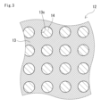
- FIG. 3 is a partially enlarged view of the cross section taken along line III-III of FIG.
- FIG. 4 is a diagram showing the positional relationship of the through holes in the second layer in the composite material according to the embodiment.
- FIG. 5 is a diagram showing another example of the positional relationship of the through holes in the second layer in the composite material according to the embodiment.
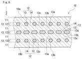
- FIG. 6 is a cross-sectional view of a composite material according to the first modification.
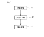
- FIG. 7 is a manufacturing process diagram of a composite material.
- FIG. 8 is an exploded perspective view of the semiconductor package according to the embodiment.
- FIG. 9 is a graph showing the linear expansion coefficient of the sample of Test Example 1.
- FIG. 10 is a graph showing the thermal conductivity of the sample of Test Example 1.
- Composite materials are required to have both high thermal conductivity and a low coefficient of linear expansion.
- One of the objectives of this disclosure is to provide a composite material that has high thermal conductivity while also being able to reduce the linear expansion coefficient.
- the composite material of the present disclosure can have a reduced linear expansion coefficient while having high thermal conductivity.
- the composite material of the present disclosure is a plate-shaped composite material having a first surface and a second surface that is the opposite side of the first surface.
- the composite material includes at least one first layer and a plurality of second layers.
- the first layer and the second layer are alternately stacked in a direction along the thickness of the composite material.
- Each layer constituting the first surface and the second surface is the first layer or the second layer.
- the first layer is a layer made of a first metal material.
- Each of the second layers has a plate made of a second metal material and a filler made of the first metal material.
- the thermal conductivity of the first metal material is higher than the thermal conductivity of the second metal material.
- the linear expansion coefficient of the second metal material is lower than the linear expansion coefficient of the first metal material.
- the plate has a plurality of through holes penetrating the plate in a direction along the thickness of the composite material.
- the filler is disposed inside the through holes.
- the through holes provided in each of the plurality of second layers are offset from each other.
- the composite material of (1) above has a high thermal conductivity and a low linear expansion coefficient. This is because it has a structure in which a first layer made of a first metallic material and a second layer having a plate made of a second metallic material and a filler made of the first metallic material are laminated.
- the term "consisting of” means that it is formed only of the material in question.
- “consisting of a first metallic material” means that it is formed only of the first metallic material.
- the composite material of (1) above can maintain the same level of thermal conductivity while reducing the linear expansion coefficient, because the through holes provided in each of the multiple second layers are offset from each other, compared to a composite material having the same configuration except that the through holes are not offset.
- the overlap rate of the through holes provided in each of the second layers may be 80% or less.
- Composite materials with an overlap rate of through holes of 80% or less tend to have a lower linear expansion coefficient.
- the opening ratio of each of the second layers may be 15% or more.
- Composite materials with an opening rate of 15% or more in the second layer tend to have high thermal conductivity.
- the opening edges of the through holes provided in at least two of the second layers may partially overlap each other.
- the composite material (4) above tends to have a low linear expansion coefficient.
- the opening edge of the through hole provided in one of the second layers among the plurality of second layers may include the opening edge of the through hole provided in another of the second layers.
- the composite material (5) above tends to have a low linear expansion coefficient.
- the volume ratio of the second metal material in the composite material may be 15% or more and 45% or less.
- the first metal material may be a metal material containing copper as a main component.
- Copper has a high thermal conductivity. If the first metal material is a metal material whose main component is copper, it is easy to increase the thermal conductivity of the composite material.
- the second metal material may be a metal material containing molybdenum as a main component.
- Molybdenum has a low coefficient of linear expansion. If the second metal material is a metal material whose main component is molybdenum, it is easy to reduce the coefficient of linear expansion of the composite material.
- the thickness of each of the second layers may be 0.05 mm or more and 35% or less of the thickness of the composite material.
- the second layer By having the thickness of the second layer be 0.05 mm or more, the second layer, which has a relatively low linear expansion coefficient, has an appropriate thickness. This makes it easier to achieve a low linear expansion coefficient for the composite material.
- the second layer By having the thickness of the second layer be 35% or less of the thickness of the composite material, the second layer, which has a relatively low thermal conductivity, does not become excessively thick. This makes it easier to achieve a high thermal conductivity for the composite material.
- the value obtained by dividing the average circular equivalent diameter of the through holes in each of the second layers by the thickness of each of the second layers may be 0.3 or more and 5.0 or less.
- Composite materials with the above value of 0.3 or more tend to have a high thermal conductivity.
- Composite materials with the above value of 5.0 or less tend to have a low linear expansion coefficient.
- the heat spreader of the present disclosure comprises any one of the composite materials described above in (1) to (10).
- the first surface forms a contact surface with a heat source.
- the heat spreader (11) above is made of a composite material that has both high thermal conductivity and a low linear expansion coefficient, making it suitable for dissipating heat from semiconductor elements.
- the semiconductor package of the present disclosure comprises any one of the composite materials (1) to (10) above and a semiconductor element.
- the semiconductor element is disposed on the first surface.
- the semiconductor package of (12) above tends to reduce the thermal stress generated at the interface between the semiconductor element and the composite material, making it difficult for the semiconductor element to be damaged and easier to dissipate heat.
- the semiconductor package of (12) above may further include a case member made of ceramics.
- the case member is disposed on the first surface so as to surround the semiconductor element.
- the semiconductor package of (13) above is less susceptible to thermal stress occurring at the interface between the case member and the composite material, making damage to the semiconductor element less likely to occur.
- a composite material 10 according to an embodiment will be described with reference to Figs. 1 to 4.
- the composite material 10 is in the form of a plate.
- the composite material 10 has a first surface 10a and a second surface 10b.
- the first surface 10a and the second surface 10b form faces of the composite material 10 that intersect in a direction along the thickness of the composite material 10.
- the second surface 10b is the opposite surface of the first surface 10a.
- the composite material 10 includes at least one first layer 11 and a plurality of second layers 12.
- the first layer 11 and the second layer 12 are alternately laminated in a direction along the thickness of the composite material 10.
- the first layer 11 is made of a first metal material.
- the second layer 12 includes a plate 13 made of a second metal material and a filler 14. As shown in Figs. 2 and 3, the plate 13 has a plurality of through holes 13c. The filler 14 is disposed inside the through holes 13c.
- One of the characteristics of the composite material 10 is that, when the composite material 10 is viewed through in the thickness direction, as shown in Figure 4, the through holes 13c provided in each of the multiple second layers 12 are offset from each other.
- the thickness of the composite material 10 is defined as thickness Tc.
- the thickness of the first layer 11 is defined as thickness T1.
- the thickness of the second layer 12 is defined as thickness T2.
- the direction along the thickness Tc of the composite material 10 is defined as the Z direction.
- the Z direction is the direction from the first surface 10a to the second surface 10b.
- the boundary between the first layer 11 and the second layer 12 is indicated by a two-dot chain line.
- the first metal material constituting the first layer 11 has a high thermal conductivity.
- the second metal material constituting the plate 13 of the second layer 12 has a low linear expansion coefficient.
- the composite material 10 has a laminated structure in which the first layer 11 and the second layer 12 are alternately laminated. The adjacent first layer 11 and the second layer 12 are in contact with each other. With such a laminated structure, the composite material 10 can achieve both a high thermal conductivity and a low linear expansion coefficient.
- the layers constituting the first surface 10a and the second surface 10b are the first layer 11 or the second layer 12. That is, the layer constituting the first surface 10a and the layer constituting the second surface 10b are layers of the same configuration. In the example shown in FIG.
- the first layer 11 and the second layer 12 are alternately laminated so that the first layer 11 is located on the first surface 10a and the second surface 10b. Unlike the example shown in FIG. 2, the first layers 11 and the second layers 12 may be alternately laminated such that the second layers 12 are located on the first surface 10a and the second surface 10b.
- the number of first layers 11 is 1 or more.
- the number of second layers 12 is 2 or more.
- the total number of stacked layers of the first layers 11 and the second layers 12 is an odd number of 3 or more.
- the number of first layers 11, the number of second layers 12, and the number of stacked layers in the composite material 10 are not particularly limited and can be appropriately selected. In the example shown in FIG. 2, the number of first layers 11 is 3, the number of second layers 12 is 2, and the total number of stacked layers is 5.
- the first layer 11 is a layer made of a first metal material.
- the thermal conductivity of the first metal material is higher than that of the second metal material described later.
- the thermal conductivity of the first metal material is, for example, twice or more of the thermal conductivity of the second metal material.
- the thermal conductivity of the first metal material is, for example, 300 W/m ⁇ K or more, and further 350 W/m ⁇ K or more.
- Thermal conductivity means thermal conductivity at room temperature.
- the first metal material is, for example, a metal material mainly composed of copper.
- Metal material mainly composed of copper means a metal material having a copper content of 50 mass% or more.
- the copper content in the first layer 11 is 50 mass% or more.
- the copper content may be 70 mass% or more.
- the first layer 11 is, for example, made of pure copper.
- "Pure copper” is a metal material made of copper and inevitable impurities constituting the remainder. Pure copper has a copper content of 99% by mass or more, particularly 99.9% by mass or more.
- the thermal conductivity of copper is 398 W/m ⁇ K at room temperature. "Room temperature” means 27°C.
- the thickness T1 of the first layer 11 is, for example, 0.025 mm or more and 30% or less of the thickness Tc of the composite material 10.
- the first layer 11, which has a relatively high thermal conductivity has an appropriate thickness. Therefore, the thermal conductivity of the composite material 10 is likely to be high.
- the thickness T1 is 30% or less of the thickness Tc, the first layer 11, which has a relatively high linear expansion coefficient, does not become excessively thick. Therefore, the linear expansion coefficient of the composite material 10 is likely to be low.
- the thickness T1 may be 0.035 mm or more and less than 30% of the thickness Tc, or 0.045 mm or more and less than 30% of the thickness Tc.
- the thickness T1 of all the first layers 11 may be the same, or the thickness T1 of some of the first layers 11 may be different.
- the thickness T1 of the first layer located at the center of the composite material 10 in the Z direction is thicker than the thicknesses T1 of the first layers located on the upper and lower sides of the composite material 10.
- the thickness Tc of the composite material 10 is determined as follows. The length in the Z direction between the first surface 10a and the second surface 10b is measured. The number of measurements is three or more. The average value of all the measured lengths is the thickness Tc.
- the thickness T1 of the first layer is determined as follows. A cross section is taken by cutting the composite material 10 in the Z direction with a cutting machine. In this cross section along the Z direction, the length in the Z direction of the first layer 11 is measured. The cross section along the Z direction is a plane that is substantially perpendicular to the first surface 10a and the second surface 10b. The number of measurements is three or more. The average value of all the measured lengths is the thickness T1.
- the second layer 12 includes a plate 13 made of a second metal material and a filler 14.
- the linear expansion coefficient of the second metal material is lower than the linear expansion coefficient of the first metal material constituting the first layer 11.
- the linear expansion coefficient of the second metal material is, for example, 0.5 times or less than the linear expansion coefficient of the first metal material.
- the linear expansion coefficient of the second metal material is, for example, 7.0 ⁇ 10 ⁇ 6 /K (7.0 ppm/K) or less, and further 6.0 ⁇ 10 ⁇ 6 /K (6.0 ppm/K) or less.
- the "linear expansion coefficient" refers to the linear expansion coefficient in a temperature range from room temperature to 800° C.
- the second metal material is, for example, a metal material containing molybdenum as a main component.
- the "metal material containing molybdenum as a main component” refers to a metal material containing 50% by mass or more of molybdenum. In other words, when the mass of the entire plate 13 is taken as 100% by mass, the molybdenum content in the plate 13 is 50% by mass or more. The molybdenum content may be 70 mass% or more.
- the plate 13 is made of, for example, pure molybdenum.
- "Pure molybdenum” is a metal material made of molybdenum and inevitable impurities constituting the remainder.
- Pure molybdenum has a molybdenum content of 99 mass% or more, particularly 99.9 mass% or more.
- the linear expansion coefficient of molybdenum is 5.7 ppm/K.
- the filler 14 is made of a first metal material. That is, the filler 14 is made of the same material as the first layer 11.
- the thickness T2 of the second layer 12 is, for example, 0.05 mm or more and 35% or less of the thickness Tc of the composite material 10.
- the second layer 12 which has a relatively low thermal conductivity, does not become excessively thick.
- the thermal conductivity of the composite material 10 tends to be high.
- the second layer 12 which has a relatively low linear expansion coefficient, has an appropriate thickness.
- the thickness T2 may be 0.10 mm or more and 35% or less of the thickness Tc, or 0.15 mm or more and 30% or less of the thickness Tc.
- the thicknesses T2 of all the second layers 12 may be the same, or the thicknesses T2 of some of the second layers 12 may be different. In the example shown in FIG. 2, the thicknesses T2 of the two second layers 12 are the same. When the thicknesses T2 of all the second layers 12 are the same, the composite material 10 is less likely to warp when the temperature of the composite material 10 rises.
- the thickness T2 of the second layer 12 is determined in the same manner as the thickness T1 of the first layer 11, as follows.
- the Z-direction length of the second layer 12 is measured in a cross section along the Z direction of the composite material 10.
- the Z-direction length of the second layer 12 is the thickness of the plate 13, i.e., the Z-direction length between the first surface 13a and the second surface 13b of the plate 13. Three or more measurements are taken. The average of all the measured lengths is the thickness T2.
- the plate 13 has a first surface 13a and a second surface 13b.
- the second surface 13b is the opposite surface to the first surface 13a.
- the first surface 13a and the second surface 13b are surfaces that intersect in the Z direction.
- the first surface 13a and the second surface 13b are surfaces that are substantially parallel to the first surface 10a and the second surface 10b.
- the multiple through holes 13c formed in the plate 13 penetrate the plate 13 in the Z direction.
- the multiple through holes 13c in the plate 13 are independent of each other. In other words, adjacent through holes 13c in the plate 13 are not connected to each other.
- the multiple through holes 13c in the plate 13 are not arranged in a three-dimensional mesh pattern, but are arranged in a regular pattern.
- the multiple through holes 13c in the plate 13 have the same shape and uniform size.
- the through hole 13c has a circular shape.
- the cross section perpendicular to the Z direction is a plane that is substantially parallel to the first surface 10a and the second surface 10b.
- the shape of the through hole 13c is not limited to a circular shape.
- the shape of the through hole 13c may be an ellipse, a polygon, or any other shape.
- the multiple through holes 13c are arranged in a lattice array. More specifically, in the cross section, the multiple through holes 13c are arranged in a square lattice pattern. In the cross section, the multiple through holes 13c may be arranged in a rectangular lattice pattern. In the cross section, the multiple through holes 13c may be arranged in a diagonal lattice pattern.
- the number of through holes 13c per mm2 is, for example, less than 3. If the number of through holes 13c is less than 3/ mm2 , the linear expansion coefficient of the composite material 10 tends to be low.
- the number of through holes 13c per mm2 is obtained by dividing the number of through holes 13c by the area of the second layer 12 in a cross section perpendicular to the Z direction.
- the area of the second layer 12 is the area of the plate 13 including the through holes 13c.
- the number of through holes 13c per mm2 may be less than 2. If the number of through holes 13c is less than 2/ mm2 , the linear expansion coefficient of the composite material 10 tends to be lower.
- the cross section of the second layer 12 perpendicular to the Z direction is exposed as follows.
- the composite material 10 is observed from the side using a digital microscope to measure the distance between the first surface 10a and the center of the plate 13 in the Z direction.
- the first surface 10a is polished using a flat polisher or an automatic rotary polisher.
- the amount of polishing is set so as to be equal to the distance between the first surface 10a and the center of the plate 13 in the Z direction measured as described above.
- the cross section of the second layer 12 perpendicular to the Z direction can also be observed using an X-ray CT (Computed Tomography) device.
- X-ray CT Computed Tomography
- the aperture ratio of the second layer 12 is, for example, 15% or more.
- the aperture ratio is obtained as follows. In a cross section passing through the center of the plate 13 in the Z direction and perpendicular to the Z direction, the sum of the aperture areas of all the through holes 13c is measured. The measured sum is divided by the area of the second layer 12 described above. The aperture area is measured using a digital microscope. The aperture area may be calculated by extracting the through holes 13c from an X-ray CT image. If the aperture ratio is 15% or more, the thermal conductivity of the composite material 10 is likely to be high. The aperture ratio may be 20% or more, 30% or more, or even 35% or more. The aperture ratio is, for example, 70% or less. The aperture ratio may be 60% or less.
- the aperture ratios of the multiple second layers 12 may be the same or different.
- the aperture ratio of the second layer 121 close to the first surface 10a and the aperture ratio of the second layer 122 close to the second surface 10b are substantially equal.
- the aperture ratios are substantially equal means that the difference in the aperture ratios of the second layers 12 is within 5%.
- the circle-equivalent diameter of the through hole 13c at any position in the Z direction is defined as the opening diameter D.
- the opening diameter D is obtained by calculating the square root of the opening area of the through hole 13c at any position in the Z direction divided by ⁇ /4.
- the opening diameter D is measured on a plane parallel to the first surface 13a.
- the opening diameter D in this example varies between the first surface 13a and the second surface 13b. That is, the opening diameter D in this example is not constant between the first surface 13a and the second surface 13b.
- the opening diameter D in this example becomes smaller from each of the first surface 13a and the second surface 13b toward the middle between the first surface 13a and the second surface 13b. That is, the opening diameter D in this example becomes smaller from the first surface 13a toward the middle between the first surface 13a and the second surface 13b, and becomes larger from the middle between the first surface 13a and the second surface 13b toward the second surface 13b.
- the opening diameter D may become smaller from the first surface 13a toward the second surface 13b, or may become smaller from the second surface 13b toward the first surface 13a.
- the opening diameter D may be constant between the first surface 13a and the second surface 13b.
- the maximum value of the opening diameter D between the first surface 13a and the second surface 13b of the plate 13 is the opening diameter Dmax.
- the opening diameter Dmax is calculated as follows.
- the shape of the through hole 13c is considered to be similar in the Z direction. If the shape of the through hole 13c in the first surface 13a is a perfect circle, the opening diameter Dmax is the maximum value of the diameter of the through hole 13c.
- the maximum value of the diameter of the through hole 13c is the maximum width of the through hole 13c in the Z direction parallel to the first surface 13a in a cross section cut in the Z direction through the diameter of the through hole 13c in the first surface 13a.
- the opening diameter Dmax is the maximum value of the equivalent diameter of a circle with an equal area of the through hole 13c.
- the maximum value of the equivalent circle diameter of the through hole 13c is the diameter of a perfect circle having the same area as the maximum area of the ellipse calculated from the maximum length of the long axis and the maximum length of the short axis of the through hole 13c in the Z direction parallel to the first surface 13a.
- the maximum length of the long axis is the maximum width of the through hole 13c parallel to the first surface 13a in the Z direction in a cross section cut in a direction along the thickness through the long axis of the through hole 13c on the first surface 13a.
- the maximum length of the short axis is calculated from the ratio of the long axis to the short axis of the through hole 13c on the first surface 13a and the maximum length of the long axis.
- the average value of the opening diameter Dmax is defined as the average equivalent circle diameter.
- the average value of the opening diameter Dmax is the sum of the opening diameters Dmax of all the through holes 13c divided by the total number of the through holes 13c.
- the value obtained by dividing the average equivalent circular diameter in the second layer 12 by the thickness T2 is, for example, 0.3 or more and 5.0 or less. If the value is 0.3 or more, the thermal conductivity of the composite material 10 is likely to be high. If the value is 5.0 or less, the linear expansion coefficient of the composite material 10 is likely to be low.
- the value obtained by dividing the average equivalent circular diameter in the second layer 12 by the thickness T2 may be 1.6 or more and less than 5.0. If the value is 1.6 or more, the thermal conductivity of the composite material 10 is likely to be higher. If the value is less than 5.0, the linear expansion coefficient of the composite material 10 is likely to be lower.
- FIG. 4 is a plan view of the composite material 10 seen through from the first surface 10a.
- FIG. 4 shows the positional relationship of the through holes 13c provided in each of the second layers 12 overlapping in the Z direction.
- the through holes 13c provided in each of the second layers 12 are offset from each other.
- the second layer 121 close to the first surface 10a is shown by a solid line
- the second layer 122 close to the second surface 10b is shown by a dashed line.
- the second layer 121 is hatched from the top to the right
- the second layer 122 is hatched from the bottom to the right.
- “Through holes are offset from each other” means that the contours of the through holes 13c provided in each of the multiple second layers 12 do not match, that is, the openings of the through holes 13c do not overlap each other.
- the opening of the through hole 13c in one second layer 12 here refers to the narrowest part of the through hole 13c when viewed through the through hole 13c in the Z direction, that is, the part with the smallest opening diameter D.
- a specific example of a state in which the through holes 13c are offset from each other is a form in which the opening edges of the through holes 13c partially overlap each other, as shown in Figure 4.
- the opening edge of the through hole 13c provided in one second layer 12 among the multiple second layers 12 partially overlaps the opening edge of the through hole 13c provided in another second layer 12. That is, it is sufficient that the opening edges of the through holes 13c provided in at least two second layers 12 partially overlap each other, and it is also possible that the opening edges of the through holes 13c provided in all of the second layers 12 partially overlap each other.
- Another specific example is a form in which the opening edge of the through hole 13c of a certain second layer 12 includes the opening edge of the through hole 13c of another second layer 12, as shown in FIG. 5.
- the opening edge of the through hole 13c provided in one second layer 12 includes the opening edge of the through hole 13c provided in another second layer 12, and it is also possible that the opening edges of the through holes 13c provided in all of the remaining second layers 12 are included.
- the through hole 13c of the second layer 121 and the through hole 13c of the second layer 122 have a part that partially overlaps.
- the shape and opening diameter Dmax of the through holes 13c of the second layer 121 and the second layer 122 are substantially the same.
- the through holes 13c of the second layer 122 are included in the through holes 13c of the second layer 121.
- the aperture diameter Dmax of the through holes 13c of the second layer 122 is smaller than the aperture diameter Dmax of the through holes 13c of the second layer 121, and the aperture ratio of the second layer 122 is smaller than the aperture ratio of the second layer 121.
- the first metal material that is continuous from the first surface 10a to the second surface 10b can be configured in a stepped shape, for example, this is included in "the through holes are offset from each other".
- the through holes 13c do not overlap at all, the interval between the adjacent through holes 13c of a certain second layer 12 is larger than the aperture diameter Dmax of the through holes 13c of another second layer 12. If the through holes 13c are offset from each other, the linear expansion coefficient of the composite material 10 is likely to be low.
- the through holes 13c of one second layer 12 are offset from the through holes 13c of any of the remaining second layers.
- the through holes 13c of all the second layers 12 may be offset from each other.
- the overlapping rate of the through holes 13c is, for example, 80% or less.
- the "overlap rate of the through holes” refers to the ratio of the through holes 13c provided in each of the second layers 12 that overlap with each other.
- the overlapping portion of the through holes 13c is the portion where all the through holes 13c of the second layer penetrate in the Z direction.
- the smaller the overlap rate of the through holes 13c the smaller the overlapping rate of the through holes 13c provided in each of the second layers 12. In other words, the ratio of the through holes 13c that are misaligned with each other is large.
- the overlap rate is 80% or less, the linear expansion coefficient of the composite material 10 is likely to be low.
- the overlap rate may be 70% or less, or even 60% or less. The smaller the overlap rate, the more likely the linear expansion coefficient of the composite material 10 is to be low.
- the overlap rate may be zero. In other words, the through holes 13c may not overlap at all.
- the overlap rate may be 5% or more, 10% or more, or even 15% or more.
- the overlapping ratio is obtained by dividing the aperture ratio of the overlapping portion of the through holes 13c when the composite material 10 is viewed in the Z direction by the average aperture ratio of all the second layers 12.
- the aperture ratio of the overlapping portion is obtained by dividing the area of the overlapping portion of the through holes 13c by the area of all the second layers 12 overlapping.
- the area of the overlapping portion of the through holes 13c is the area surrounded by a part of the opening edge of the through hole 13c of the second layer 121 and a part of the opening edge of the through hole 13c of the second layer 122.
- the overlapping portion of the through holes 13c is a spindle-shaped region where the through hole 13c of the second layer 121 and the through hole 13c of the second layer 122 overlap.
- the area of the overlapping portion of the through holes 13c is equal to the area of the through hole 13c of the second layer 122 included in the through hole 13c of the second layer 121.
- the overlapping area of the second layers 12 is the area of the region where the second layers 121 and 122 overlap.
- the area of the overlapping portion of the through holes 13c and the area of the overlapping second layers 12 can be obtained from an X-ray CT image.
- the through holes 13c When obtaining the area of the overlapping portion of the through holes 13c, some of the through holes 13c that fall outside the range where all of the second layers 12 overlap are ignored. The some of the through holes 13c that fall outside the range where the second layers 12 overlap are the through holes 13c of a certain second layer 12 that do not overlap with other second layers.
- the method for obtaining the aperture ratio of the second layer 12 is as described above.
- the volume ratio of the second metal material in the composite material 10 is, for example, 15% or more and 45% or less.
- the volume ratio is the proportion of the second metal material when the volume of the composite material 10 is 100% by volume.
- a composite material 10 having the volume ratio of 15% or more is likely to have a low linear expansion coefficient, which will be described later.
- a composite material 10 having the volume ratio of 45% or less is likely to have a high thermal conductivity, which will be described later.
- the volume ratio may be more than 15% and 40% or less, or 17% or more and 35% or less.
- the volume ratio of the second metallic material is obtained as follows.
- the weight ratio of the first metallic material to the second metallic material is obtained by inductively coupled plasma optical emission spectroscopy (ICP-OES).
- the volume ratio is calculated from the obtained weight ratio and the density of each substance.
- the first metallic material is, for example, copper.
- the density of copper is 8.96 g/ cm3 .
- the second metallic material is, for example, molybdenum.
- the density of molybdenum is 10.2 g/ cm3 .
- the linear expansion coefficient of the composite material 10 is, for example, 9.0 ppm/K or less.
- the linear expansion coefficient of the composite material 10 is the linear expansion coefficient in a direction perpendicular to the Z direction when the temperature changes from room temperature to 800° C.
- the linear expansion coefficient of the composite material 10 may be 8.8 ppm/K or less, or 8.6 ppm/K or less.
- the linear expansion coefficient of the composite material 10 is calculated by measuring the expansion displacement of the composite material 10 in a direction perpendicular to the Z direction in a temperature range from room temperature to 800°C using a TD5000SA manufactured by Bruker AXS.
- a sample used to measure the linear expansion coefficient of the composite material 10 is cut out from the composite material 10.
- the planar shape of the sample is rectangular.
- the size of the planar shape of the sample is 5 mm x 15 mm.
- the linear expansion coefficient of the composite material 10 is the average value of the linear expansion coefficients of the three samples.
- the thermal conductivity of the composite material 10 is, for example, 290 W/m ⁇ K or more.
- the thermal conductivity of the composite material 10 is the thermal conductivity of the composite material 10 in the Z direction at room temperature.
- the thermal conductivity of the composite material 10 may be 300 W/m ⁇ K or more, 320 W/m ⁇ K or more, or 350 W/m ⁇ K or more.
- the thermal conductivity of the composite material 10 is calculated based on the thermal diffusion coefficient of the composite material 10 and the volume ratio and specific heat of each of the constituent materials of the composite material 10.
- the thermal diffusion coefficient of the composite material 10 is measured using a laser flash method.
- a NETZSCH LFA457 MicroFlash is used as a measuring device for the thermal diffusion coefficient of the composite material 10.
- a sample used to measure the thermal diffusion coefficient of the composite material 10 is cut out from the composite material 10.
- the planar shape of the sample is circular.
- the diameter of the planar shape of the sample is 10 mm.
- the specific heat of each of the constituent materials of the composite material 10 is determined based on "Metal Data Book, 4th Edition" (2004, Maruzen Publishing), edited by the Japan Institute of Metals.
- the thermal conductivity of a pure copper sample of the same shape Prior to measuring the thermal conductivity of the composite material 10, the thermal conductivity of a pure copper sample of the same shape is measured under the same conditions, and the measurement result is corrected using the result as a reference.
- the thermal conductivity of the composite material 10 is the average value of the thermal conductivities of the three samples.
- the specific heat of copper is 386 J/(kg ⁇ K).
- the specific heat of molybdenum is 251 J/(kg ⁇ K).
- FIG. 6 shows a cross section of the composite material 10 cut in the Z direction, similarly to FIG. 2.
- the number of first layers 11 is 4, the number of second layers 12 is 3, and the total number of layers is 7.
- all the first layers 11 have the same thickness.
- the composite material 10 in the example shown in FIG. 6 has a symmetrical structure with the second layer 123 disposed at the center of the composite material 10 in the Z direction sandwiched therebetween. Specifically, the aperture ratios of the second layer 121 and the second layer 122 disposed on either side of the second layer 123 are substantially equal. In the example shown in FIG.
- the aperture ratio of the second layer 123 is different from the aperture ratios of the second layer 121 and the second layer 122. Specifically, the aperture ratio of the second layer 123 is smaller than the aperture ratios of the second layer 121 and the second layer 122. In the case of such a symmetrical structure, a difference in the linear expansion coefficient is unlikely to occur between an upper portion closer to the first surface 10a than the second layer 123 and a lower portion closer to the second surface 10b than the second layer 123. Therefore, when the temperature of the composite material 10 increases, the composite material 10 is unlikely to warp.
- the composite material 10 can be manufactured by a composite material manufacturing method including a preparation step S1, a hole drilling step S2, and a joining step S3 shown in FIG.
- the first plate material is a plate material made of a first metallic material.
- the first plate material is, for example, a plate material made of a metallic material whose main component is copper.
- the second plate material is a plate material made of a second metallic material.
- the second plate material is, for example, a plate material made of a metallic material whose main component is molybdenum.
- the thickness of each of the first plate material and the second plate material to be prepared is appropriately selected depending on the thickness of the composite material 10 to be produced, the volume ratio of the second metallic material in the composite material 10, and the respective numbers of the first layers 11 and second layers 12.
- the second plate material is drilled to produce a second processed plate material in which a plurality of through holes 13c are formed penetrating in a direction along the thickness of the second plate material.
- the second processed plate material becomes plate 13.
- the drilling process is performed, for example, by etching or laser irradiation.
- the drilling process may be performed from both the first and second surfaces of the second plate material, or may be performed only from the first or second surface. By drilling from both the first and second surfaces of the second plate material, through holes 13c as shown in FIG. 2 are formed.
- a second processed plate material is produced in which through holes 13c are formed in which the opening diameter D becomes smaller from each of the first surface 13a and the second surface 13b toward the middle between the first surface 13a and the second surface 13b.
- a second processed plate material is produced in which through holes 13c are formed, the opening diameter D of which decreases from the first surface 13a to the second surface 13b or from the second surface 13b to the first surface 13a (not shown).
- the laminate is heated and pressurized.
- the laminate is produced by alternately stacking the first plate material and the second processed plate material inside the mold.
- the first plate material and the second processed plate material are stacked so that the first plate material is disposed at the bottom layer and the top layer of the laminate, respectively, or the second processed plate material is disposed at the bottom layer and the top layer of the laminate, respectively.
- the mold is made of, for example, graphite.
- the heating temperature is a temperature that is lower than the melting point of the first plate material and at which the first plate material is sufficiently softened.
- the heating temperature is, for example, 1000°C.
- Pressurization is performed in a direction along the thickness of the laminate. Pressurization is performed at a pressure necessary to flow the first plate material softened by heating.
- the pressure is, for example, 50 MPa or more.
- the first plate material and the second processed plate material are joined to each other by the above heating and pressing.
- the above heating and pressure causes a portion of the first metal material constituting the first plate to flow, filling the through holes 13c of the second processed plate to become the filler 14.
- the filler 14 filled in the through holes 13c and the second processed plate become the second layer 12.
- the remaining portion of the first plate that is not filled in the through holes 13c becomes the first layer 11.
- the composite material 10 having the structure shown in FIG. 2 is manufactured.
- the semiconductor package of the embodiment will be described with reference to Fig. 8.
- the semiconductor package 100 includes a composite material 10, a semiconductor element 30, a case member 40, a lid 41, and terminals 50a and 50b.
- the composite material 10 constitutes the heat spreader of the semiconductor package 100.
- the semiconductor element 30 is a heat source during operation.
- the semiconductor element 30 is disposed on the first surface 10a.
- a heat transfer member may be interposed between the semiconductor element 30 and the first surface 10a.
- the heat transfer member is, for example, a bonding material such as solder or nano silver paste.
- the case member 40 is made of, for example, a ceramic material.
- the ceramic material is, for example, alumina (Al 2 O 3 ).
- the case member 40 has a rectangular frame shape.
- the case member 40 is disposed on the first surface 10a so as to surround the semiconductor element 30.
- the case member 40 and the first surface 10a are joined by, for example, brazing.
- the composite material 10 is exposed to high temperatures.
- the high temperature is, for example, about 800° C.
- the difference between the linear expansion coefficient of the composite material 10 itself and the linear expansion coefficient of the alumina constituting the case member 40 is small.
- Terminals 50a and 50b are inserted into case member 40. First ends of terminals 50a and 50b are located within a space defined by first surface 10a, case member 40, and lid 41. Second ends of terminals 50a and 50b are located outside the space. Terminals 50a and 50b are made of, for example, a metal material. The metal material is, for example, Kovar.
- terminals 50a and 50b are electrically connected to semiconductor element 30.
- the semiconductor package 100 is electrically connected to a device or circuit other than semiconductor package 100 by the second ends of terminals 50a and 50b.
- a heat dissipation member 60 is attached to the second surface 10b.
- the heat dissipation member 60 is, for example, a metal plate with a flow path formed inside through which a refrigerant flows.
- the heat dissipation member 60 is not limited to this.
- the heat dissipation member 60 may be, for example, a cooling fin.
- a heat transfer member (not shown) may be interposed between the heat dissipation member 60 and the second surface 10b.
- Each second plate material was drilled.
- a second processed plate material was produced in which a plurality of through holes 13c were formed by drilling in a direction along the thickness of each second plate material. The drilling was performed by irradiating the laser from both the first and second surfaces of each second plate material.
- the first plate material and the second processed plate material were arranged alternately in order inside a graphite mold. With this arrangement, a laminate was produced in which the first plate material, the second processed plate material, the first plate material, the second processed plate material, and the first plate material were arranged in order from the top layer to the bottom layer.
- Table 1 shows the thickness of each plate material prepared. The first to fifth layers in Table 1 correspond to the order in which the plates were stacked from the top layer.
- the first layer refers to the plate material arranged at the top of the laminate.
- the second layer refers to the plate material arranged second from the top layer.
- the "Material” column in Table 1 shows the material of the plate material constituting each layer of the laminate.
- the material of the plate is "Cu”
- the material of the plate is "Mo”
- the laminate was joined by hot pressing under conditions of a temperature of 1000°C, a time of 60 minutes, and a pressure of 50 MPa.
- the second processed plate of the second layer and the second processed plate of the fourth layer were arranged so as to be shifted from each other in a direction perpendicular to the Z direction.
- the composite material produced had the first layer 11 and the second layer 12 alternately stacked in the Z direction so that the first layer 11 was located on the first surface 10a and the second surface 10b.
- the composite material 10 has a layered structure in which the first layer 11, the second layer 12, the first layer 11, the second layer 12, and the first layer 11 are arranged in this order from the first surface 10a.
- the number of first layers 11 was 3, the number of second layers 12 was 2, and the total number of layers was 5.
- the thickness of the composite material after bonding was about 1 mm.
- the second layer 12 was composed of a plate 13 in which a plurality of through holes 13c were formed and a filler 14 arranged inside each through hole 13c.
- the shape of the through hole 13c was a perfect circle.
- Figure 9 is a graph showing the relationship between the overlap ratio of the through holes and the linear expansion coefficient for each sample.
- the horizontal axis of Figure 9 represents the overlap ratio, and the vertical axis represents the linear expansion coefficient.
- the dashed lines in Figure 9 are approximate straight lines showing the relationship between the overlap ratio and the linear expansion coefficient for Samples No. 1-1 to 1-6.
- Figure 10 is a graph showing the relationship between the overlap ratio of the through holes and the thermal conductivity for each sample.
- the horizontal axis of Figure 10 represents the overlap ratio
- the vertical axis represents the thermal conductivity.
Landscapes
- Cooling Or The Like Of Semiconductors Or Solid State Devices (AREA)
- Laminated Bodies (AREA)
Priority Applications (1)
| Application Number | Priority Date | Filing Date | Title |
|---|---|---|---|
| JP2025526777A JP7744553B1 (ja) | 2023-12-01 | 2024-11-07 | 複合材料、ヒートスプレッダ、および半導体パッケージ |
Applications Claiming Priority (2)
| Application Number | Priority Date | Filing Date | Title |
|---|---|---|---|
| JP2023203978 | 2023-12-01 | ||
| JP2023-203978 | 2023-12-01 |
Publications (1)
| Publication Number | Publication Date |
|---|---|
| WO2025115552A1 true WO2025115552A1 (ja) | 2025-06-05 |
Family
ID=95896788
Family Applications (1)
| Application Number | Title | Priority Date | Filing Date |
|---|---|---|---|
| PCT/JP2024/039629 Pending WO2025115552A1 (ja) | 2023-12-01 | 2024-11-07 | 複合材料、ヒートスプレッダ、および半導体パッケージ |
Country Status (2)
| Country | Link |
|---|---|
| JP (1) | JP7744553B1 (https=) |
| WO (1) | WO2025115552A1 (https=) |
Citations (7)
| Publication number | Priority date | Publication date | Assignee | Title |
|---|---|---|---|---|
| JPH0313331A (ja) * | 1989-06-10 | 1991-01-22 | Sumitomo Special Metals Co Ltd | 熱膨張係数及び熱伝導率可変複合材料 |
| JPH03227621A (ja) * | 1989-12-12 | 1991-10-08 | Sumitomo Special Metals Co Ltd | 熱伝導複合材料 |
| JPH09312364A (ja) * | 1996-05-22 | 1997-12-02 | Hitachi Metals Ltd | 電子部品用複合材料およびその製造方法 |
| JP2017152606A (ja) * | 2016-02-26 | 2017-08-31 | 京セラ株式会社 | 放熱基板およびそれを用いた半導体パッケージならびに半導体モジュール |
| JP2018182088A (ja) * | 2017-04-14 | 2018-11-15 | 株式会社半導体熱研究所 | 放熱基板、放熱基板電極、半導体パッケージ、及び半導体モジュール |
| JP2020198333A (ja) * | 2019-05-31 | 2020-12-10 | アイシン精機株式会社 | 熱伝導シート及び熱伝導シート製造方法 |
| WO2022030197A1 (ja) * | 2020-08-06 | 2022-02-10 | 住友電気工業株式会社 | 複合材料、ヒートスプレッダ及び半導体パッケージ |
-
2024
- 2024-11-07 WO PCT/JP2024/039629 patent/WO2025115552A1/ja active Pending
- 2024-11-07 JP JP2025526777A patent/JP7744553B1/ja active Active
Patent Citations (7)
| Publication number | Priority date | Publication date | Assignee | Title |
|---|---|---|---|---|
| JPH0313331A (ja) * | 1989-06-10 | 1991-01-22 | Sumitomo Special Metals Co Ltd | 熱膨張係数及び熱伝導率可変複合材料 |
| JPH03227621A (ja) * | 1989-12-12 | 1991-10-08 | Sumitomo Special Metals Co Ltd | 熱伝導複合材料 |
| JPH09312364A (ja) * | 1996-05-22 | 1997-12-02 | Hitachi Metals Ltd | 電子部品用複合材料およびその製造方法 |
| JP2017152606A (ja) * | 2016-02-26 | 2017-08-31 | 京セラ株式会社 | 放熱基板およびそれを用いた半導体パッケージならびに半導体モジュール |
| JP2018182088A (ja) * | 2017-04-14 | 2018-11-15 | 株式会社半導体熱研究所 | 放熱基板、放熱基板電極、半導体パッケージ、及び半導体モジュール |
| JP2020198333A (ja) * | 2019-05-31 | 2020-12-10 | アイシン精機株式会社 | 熱伝導シート及び熱伝導シート製造方法 |
| WO2022030197A1 (ja) * | 2020-08-06 | 2022-02-10 | 住友電気工業株式会社 | 複合材料、ヒートスプレッダ及び半導体パッケージ |
Also Published As
| Publication number | Publication date |
|---|---|
| JPWO2025115552A1 (https=) | 2025-06-05 |
| JP7744553B1 (ja) | 2025-09-25 |
Similar Documents
| Publication | Publication Date | Title |
|---|---|---|
| US6032362A (en) | Method for producing a heat spreader and semiconductor device with a heat spreader | |
| US7951467B2 (en) | Cladding material and its manufacturing method, press-forming method, and heat sink using cladding material | |
| US6129993A (en) | Heat spreader and method of making the same | |
| CN101160658A (zh) | 具有改善热导率的难熔金属衬底 | |
| WO2021040030A1 (ja) | 放熱板、半導体パッケージ及び半導体モジュール | |
| US12525503B2 (en) | Composite material, heat spreader and semiconductor package | |
| JP6754973B2 (ja) | グラファイト放熱板 | |
| US11373923B2 (en) | Heat sink with coiled metal-wire material | |
| JP7744553B1 (ja) | 複合材料、ヒートスプレッダ、および半導体パッケージ | |
| JP2022178275A (ja) | 放熱板および半導体パッケージ | |
| JP7658992B2 (ja) | 複合材料、半導体パッケージ及び複合材料の製造方法 | |
| JP2024114530A (ja) | 複合材料、ヒートスプレッダ、および半導体パッケージ | |
| JP2010056148A (ja) | クラッド材、クラッド材を用いた放熱基板 | |
| KR102945417B1 (ko) | 복합 재료, 히트 스프레더 및 반도체 패키지 | |
| JP7700510B2 (ja) | 放熱板および半導体パッケージ | |
| JP7630771B2 (ja) | 放熱板および半導体パッケージ | |
| JP2022517598A (ja) | 放熱板材 | |
| WO2025216198A1 (ja) | セラミックス銅接合体、セラミックス銅回路基板、およびセラミックス銅接合体の製造方法 | |
| WO2022172855A1 (ja) | 複合材料、ヒートスプレッダ及び半導体パッケージ | |
| JP7302446B2 (ja) | 放熱装置 | |
| JP4179055B2 (ja) | パワーモジュール用基板並びに放熱体及び放熱体の製造方法 | |
| JPH11297908A (ja) | ヒ―トスプレッダおよびこれを用いた半導体装置ならびにヒ―トスプレッダの製造方法 | |
| JP2022169059A (ja) | パッケージ | |
| JP2005019896A (ja) | 半導体素子収納用パッケージおよび半導体装置 |
Legal Events
| Date | Code | Title | Description |
|---|---|---|---|
| ENP | Entry into the national phase |
Ref document number: 2025526777 Country of ref document: JP Kind code of ref document: A |
|
| WWE | Wipo information: entry into national phase |
Ref document number: 2025526777 Country of ref document: JP |
|
| 121 | Ep: the epo has been informed by wipo that ep was designated in this application |
Ref document number: 24897239 Country of ref document: EP Kind code of ref document: A1 |