WO2025105078A1 - 熱媒体供給装置 - Google Patents
熱媒体供給装置 Download PDFInfo
- Publication number
- WO2025105078A1 WO2025105078A1 PCT/JP2024/036011 JP2024036011W WO2025105078A1 WO 2025105078 A1 WO2025105078 A1 WO 2025105078A1 JP 2024036011 W JP2024036011 W JP 2024036011W WO 2025105078 A1 WO2025105078 A1 WO 2025105078A1
- Authority
- WO
- WIPO (PCT)
- Prior art keywords
- cooling
- heat medium
- heating
- return pipe
- temperature
- Prior art date
- Legal status (The legal status is an assumption and is not a legal conclusion. Google has not performed a legal analysis and makes no representation as to the accuracy of the status listed.)
- Pending
Links
Images




Classifications
-
- G—PHYSICS
- G05—CONTROLLING; REGULATING
- G05D—SYSTEMS FOR CONTROLLING OR REGULATING NON-ELECTRIC VARIABLES
- G05D23/00—Control of temperature
- G05D23/01—Control of temperature without auxiliary power
- G05D23/13—Control of temperature without auxiliary power by varying the mixing ratio of two fluids having different temperatures
-
- H—ELECTRICITY
- H10—SEMICONDUCTOR DEVICES; ELECTRIC SOLID-STATE DEVICES NOT OTHERWISE PROVIDED FOR
- H10P—GENERIC PROCESSES OR APPARATUS FOR THE MANUFACTURE OR TREATMENT OF DEVICES COVERED BY CLASS H10
- H10P95/00—Generic processes or apparatus for manufacture or treatments not covered by the other groups of this subclass
Definitions
- the present invention relates to a heat medium supplying device that supplies a heat medium to semiconductor manufacturing equipment, such as an etching device, a CVD device, or a PVD device, to adjust the temperature of the semiconductor manufacturing equipment.
- semiconductor manufacturing equipment such as an etching device, a CVD device, or a PVD device
- Semiconductor manufacturing equipment e.g., etching equipment, CVD equipment, PVD equipment
- etching equipment for manufacturing semiconductor devices is configured to carry out the manufacturing process while controlling the processing temperature.
- the processing temperature of the wafer is adjusted by flowing a temperature-regulated liquid as a heat medium through a flow path formed in a susceptor that supports the wafer.
- FIG. 5 is a schematic diagram showing a conventional example of a heat medium supplying device that supplies a heat medium to a semiconductor manufacturing device.
- the heat medium supplying device 500 includes a heating device 501 that heats the heat medium, and a cooling device 502 that cools the heat medium.
- the heat medium is stored in a heating side tank 504 and a cooling side tank 505.
- the heat medium heated by the heating device 501 is transferred to the heating side tank 504, and is further transferred from the heating side tank 504 into the heat medium mixer 507.
- the heat medium stored in the cooling side tank 505 is transferred to the cooling device 502, where it is cooled.
- the cooled heat medium is transferred to the heat medium mixer 507.
- the heated heat medium and cooled heat medium are mixed in heat medium mixer 507 and adjusted to the temperature required for semiconductor manufacturing equipment 510.
- the temperature-adjusted heat medium is sent to semiconductor manufacturing equipment 510, which maintains the semiconductor manufacturing equipment 510 at the target temperature.
- the heat medium that has passed through semiconductor manufacturing equipment 510 is returned to heat medium mixer 507, where it is diverted and transferred to heating side tank 504 and cooling side tank 505. In this way, the heat medium circulates between heat medium supply device 500 and semiconductor manufacturing equipment 510.
- the target temperature for wafer processing in semiconductor manufacturing equipment 510 can fluctuate significantly during wafer processing. Such fluctuations in the target temperature can cause a sudden change in the temperature of the heat medium returning from semiconductor manufacturing equipment 510 to heating side tank 504 and cooling side tank 505 via heat medium mixer 507. As a result, a high load is temporarily placed on heating device 501 and cooling device 502, and it can take a long time for the temperature of the heat medium supplied to heat medium mixer 507 to stabilize.
- the present invention provides a heat medium supplying device that can prevent a high load on the cooling device and supply a heat medium at a stable temperature when the temperature of the heat medium returning from the semiconductor manufacturing equipment changes suddenly.
- the present invention also provides a heat medium supplying device that can prevent a high load on the heating device and supply a heat medium at a stable temperature when the temperature of the heat medium returning from the semiconductor manufacturing equipment changes suddenly.
- a heat medium supplying device for supplying a heat medium for adjusting the temperature of a semiconductor manufacturing equipment includes a heating device for heating the heat medium, a cooling device for cooling the heat medium, a heating medium transfer pipe for sending the heated heat medium to the semiconductor manufacturing equipment, a cooling medium transfer pipe for sending the cooled heat medium to the semiconductor manufacturing equipment, a heating side tank and a cooling side tank for holding the heat medium, a heating side return pipe for returning the heat medium that has passed through the semiconductor manufacturing equipment to the heating side tank, a cooling side return pipe for returning the heat medium that has passed through the semiconductor manufacturing equipment to the cooling side tank, a cooling side temperature measuring device provided in the cooling side return pipe for measuring the temperature of the heat medium in the cooling side return pipe, and a cooling side temperature measuring device for measuring the temperature of the heat medium in the cooling side return pipe from the cooling side tank.
- a heat medium supply device includes a cooling side outlet pipe that transfers the heat medium to the cooling device, a cooling side bypass pipe that extends from the cooling side return pipe to the cooling side outlet pipe, bypassing the cooling side tank, a cooling side bypass valve provided in the cooling side bypass pipe, and an operation control unit that controls the operation of the cooling side bypass valve, and the operation control unit is configured to open the cooling side bypass valve when the temperature of the heat medium in the cooling side return pipe measured by the cooling side temperature measuring device is within a preset allowable low temperature range, and to close the cooling side bypass valve when the temperature of the heat medium in the cooling side return pipe measured by the cooling side temperature measuring device is outside the allowable low temperature range.
- the cooling side bypass valve When the temperature of the heat medium in the cooling side return pipe is outside the allowable low temperature range, the cooling side bypass valve is closed and the heat medium in the cooling side return pipe is transferred into the cooling side tank. More specifically, when the temperature of the heat medium in the cooling side return pipe is lower than the lower limit of the allowable low temperature range, the low temperature heat medium flows into the cooling side tank and is stored in the cooling side tank. During the operation of the semiconductor manufacturing equipment, a relatively high temperature heat medium may temporarily return through the cooling side return pipe. When the temperature of the heat medium in the cooling side return pipe is higher than the upper limit of the allowable low temperature range, the high temperature heat medium flows into the cooling side tank.
- the cooling-side bypass valve operates based on whether the temperature of the heat medium in the cooling-side return pipe is within the allowable low-temperature range, thereby stabilizing the load on the cooling device.
- the heat medium supplying device further includes a heating side temperature measuring device provided in the heating side return pipe for measuring the temperature of the heat medium in the heating side return pipe, a heating side outlet pipe for transporting the heat medium from the heating side tank to the heating device, a heating side bypass pipe that bypasses the heating side tank and extends from the heating side return pipe to the heating side outlet pipe, and a heating side bypass valve provided in the heating side bypass pipe, and the operation control unit is configured to open the heating side bypass valve when the temperature of the heat medium in the heating side return pipe measured by the heating side temperature measuring device is within a preset allowable high temperature range, and close the heating side bypass valve when the temperature of the heat medium in the heating side return pipe measured by the heating side temperature measuring device is outside the allowable high temperature range.
- a heating side temperature measuring device provided in the heating side return pipe for measuring the temperature of the heat medium in the heating side return pipe
- a heating side outlet pipe for transporting the heat medium from the heating side tank to the heating device
- a heating side bypass pipe that bypasses the
- the heating side bypass valve is closed, and the heat medium in the heating side return pipe is transferred to the heating side tank. More specifically, when the temperature of the heat medium in the heating side return pipe is higher than the upper limit of the allowable high temperature range, the high temperature heat medium flows into the heating side tank and is stored in the heating side tank. When the temperature of the heat medium in the heating side return pipe is lower than the lower limit of the allowable high temperature range, the low temperature heat medium also flows into the heating side tank. The low temperature heat medium is mixed with the heat medium in the heating side tank, and the heat medium that is lower than the lower limit of the allowable high temperature range that flows into the heating side tank is heated.
- the temperature of the heat medium flowing from the heating side tank through the heating side outlet pipe to the heating device is higher than the temperature of the heat medium in the heating side return pipe, and the load on the heating device can be reduced compared to when the low temperature heat medium is directly supplied to the heating device.
- the load on the heating device is not large. In this way, the heating side bypass valve operates based on whether the temperature of the heat medium in the heating side return pipe is within the allowable high temperature range, thereby stabilizing the load on the heating device.
- the semiconductor manufacturing equipment is a plurality of semiconductor manufacturing equipment, and the heating medium transfer pipe, the cooling medium transfer pipe, the heating side return pipe, and the cooling side return pipe are each connected to the plurality of semiconductor manufacturing equipment.
- a heat medium supplying device for supplying a heat medium for adjusting the temperature of a semiconductor manufacturing equipment includes a heating device for heating the heat medium, a cooling device for cooling the heat medium, a heating medium transfer pipe for sending the heated heat medium to the semiconductor manufacturing equipment, a cooling medium transfer pipe for sending the cooled heat medium to the semiconductor manufacturing equipment, a heating side tank and a cooling side tank for holding the heat medium, a heating side return pipe for returning the heat medium that has passed through the semiconductor manufacturing equipment to the heating side tank, a cooling side return pipe for returning the heat medium that has passed through the semiconductor manufacturing equipment to the cooling side tank, a heating side temperature measuring device provided in the heating side return pipe for measuring the temperature of the heat medium in the heating side return pipe, and a cooling side tank for transferring the heat medium from the heating side tank to the cooling side tank.
- the heat medium supply device includes a heating side outlet pipe that transfers the heat medium to the heating device, a heating side bypass pipe that extends from the heating side return pipe to the heating side outlet pipe, bypassing the heating side tank, a heating side bypass valve provided in the heating side bypass pipe, and an operation control unit that controls the operation of the cooling side bypass valve, and the operation control unit is configured to open the heating side bypass valve when the temperature of the heat medium in the heating side return pipe measured by the heating side temperature measuring device is within a preset allowable high temperature range, and to close the heating side bypass valve when the temperature of the heat medium in the heating side return pipe measured by the heating side temperature measuring device is outside the allowable high temperature range.
- the heating side bypass valve is closed, and the heat medium in the heating side return pipe is transferred to the heating side tank. More specifically, when the temperature of the heat medium in the heating side return pipe is higher than the upper limit of the allowable high temperature range, the high temperature heat medium flows into the heating side tank and is stored in the heating side tank. When the temperature of the heat medium in the heating side return pipe is lower than the lower limit of the allowable high temperature range, the low temperature heat medium also flows into the heating side tank. The low temperature heat medium is mixed with the heat medium in the heating side tank, and the heat medium that is lower than the lower limit of the allowable high temperature range that flows into the heating side tank is heated.
- the temperature of the heat medium flowing from the heating side tank through the heating side outlet pipe to the heating device is higher than the temperature of the heat medium in the heating side return pipe, and the load on the heating device can be reduced compared to when the low temperature heat medium is directly supplied to the heating device.
- the load on the heating device is not large. In this way, the heating side bypass valve operates based on whether the temperature of the heat medium in the heating side return pipe is within the allowable high temperature range, thereby stabilizing the load on the heating device.
- the heat medium supply device further includes a cooling side temperature measuring device provided in the cooling side return pipe for measuring the temperature of the heat medium in the cooling side return pipe, a cooling side outlet pipe for transporting the heat medium from the cooling side tank to the cooling device, a cooling side bypass pipe that bypasses the cooling side tank from the cooling side return pipe to the cooling side outlet pipe, and a cooling side bypass valve provided in the cooling side bypass pipe, and the operation control unit is configured to open the cooling side bypass valve when the temperature of the heat medium in the cooling side return pipe measured by the cooling side temperature measuring device is within a preset allowable low temperature range, and close the cooling side bypass valve when the temperature of the heat medium in the cooling side return pipe measured by the cooling side temperature measuring device is outside the allowable low temperature range.
- a cooling side temperature measuring device provided in the cooling side return pipe for measuring the temperature of the heat medium in the cooling side return pipe
- a cooling side outlet pipe for transporting the heat medium from the cooling side tank to the cooling device
- a cooling side bypass pipe that bypasses the cooling side tank from
- the cooling side bypass valve When the temperature of the heat medium in the cooling side return pipe is outside the allowable low temperature range, the cooling side bypass valve is closed and the heat medium in the cooling side return pipe is transferred into the cooling side tank. More specifically, when the temperature of the heat medium in the cooling side return pipe is lower than the lower limit of the allowable low temperature range, the low temperature heat medium flows into the cooling side tank and is stored in the cooling side tank. During the operation of the semiconductor manufacturing equipment, a relatively high temperature heat medium may temporarily return through the cooling side return pipe. When the temperature of the heat medium in the cooling side return pipe is higher than the upper limit of the allowable low temperature range, the high temperature heat medium flows into the cooling side tank.
- the cooling-side bypass valve operates based on whether the temperature of the heat medium in the cooling-side return pipe is within the allowable low-temperature range, thereby stabilizing the load on the cooling device.
- the semiconductor manufacturing equipment is a plurality of semiconductor manufacturing equipment, and the heating medium transfer pipe, the cooling medium transfer pipe, the heating side return pipe, and the cooling side return pipe are each connected to the plurality of semiconductor manufacturing equipment.
- the cooling side bypass valve operates based on whether the temperature of the heat medium in the cooling side return pipe is within an allowable low temperature range, thereby stabilizing the load on the cooling device.
- the heating side bypass valve operates based on whether the temperature of the heat medium in the heating side return pipe is within the allowable high temperature range, thereby stabilizing the load on the heating device.
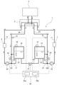
- FIG. 1 is a schematic diagram illustrating an embodiment of a semiconductor manufacturing system including a heat medium supply device and a semiconductor manufacturing device.
- FIG. 11 is a schematic diagram showing another embodiment of the heat medium supplying device.
- FIG. 11 is a schematic diagram showing still another embodiment of the heat medium supplying device.
- 1 is a schematic diagram illustrating an embodiment of a semiconductor manufacturing system including a heat medium supply device and a plurality of semiconductor manufacturing devices;
- FIG. 1 is a schematic diagram showing a conventional example of a heat medium supplying device.
- FIG. 1 is a schematic diagram showing one embodiment of a semiconductor manufacturing system including a heat medium supplying device 1 and a semiconductor manufacturing device 2.
- the heat medium supplying device 1 is configured to supply a heat medium to the semiconductor manufacturing device 2 (e.g., an etching device, a CVD device, a PVD device, etc.) to adjust the temperature of the semiconductor manufacturing device 2.
- the semiconductor manufacturing device 2 e.g., an etching device, a CVD device, a PVD device, etc.
- the semiconductor manufacturing system includes a heat medium supplying device 1, a heat medium mixing device 5 connected to the heat medium supplying device 1, and a semiconductor manufacturing device 2 connected to the heat medium mixing device 5.
- the heat medium supplying device 1 is connected to the semiconductor manufacturing device 2 via the heat medium mixing device 5.
- an etching device that performs a dry etching process on a wafer is used as the semiconductor manufacturing device 2, but the semiconductor manufacturing device 2 is not limited to this embodiment.
- the heat medium supplying device 1 includes a heating device 7 that heats the heat medium, a cooling device 8 that cools the heat medium, a heating medium transfer pipe 11 that sends the heated heat medium to the semiconductor manufacturing equipment 2, a cooling medium transfer pipe 12 that sends the cooled heat medium to the semiconductor manufacturing equipment 2, and a heating side tank 15 and a cooling side tank 16 that hold the heat medium.
- the heat medium supplying device 1 has a heat insulating material 18 that covers the entire outer surface of the heating side tank 15, and a heat insulating material 19 that covers the entire outer surface of the cooling side tank 16.
- the heat insulating materials 18, 19 are configured to maintain the temperature of the heat medium held in the heating side tank 15 and the cooling side tank 16.
- the heating medium transfer pipe 11 extends from the heating side tank 15 to the heating medium mixer 5, and the cooling medium transfer pipe 12 extends from the cooling device 8 to the heating medium mixer 5.
- the heating medium supply device 1 further includes a cooling side outlet pipe 17 that transfers the heating medium from the cooling side tank 16 to the cooling device 8.
- the cooling side outlet pipe 17 extends from the cooling side tank 16 to the cooling device 8.
- the cooling side outlet pipe 17 is located upstream of the cooling medium transfer pipe 12.
- the heating medium transfer pipe 11 and the cooling medium transfer pipe 12 are connected to the heating medium mixer 5 and communicate with the semiconductor manufacturing equipment 2 via the heating medium mixer 5.
- the heating medium mixer 5 is equipped with a plurality of flow control valves (not shown) that communicate with the heating medium transfer pipe 11 and the cooling medium transfer pipe 12, respectively.
- the heating medium mixer 5 is configured to adjust the temperature required for the semiconductor manufacturing equipment 2 by mixing the heated and cooled heat medium while adjusting the flow rates of the heated and cooled heat medium.
- a fluorine-based inert liquid is used as the heat medium.
- An example of the heating device 7 is an electric heater.
- An example of the cooling device 8 is a vapor compression refrigerator, an absorption refrigerator, etc.
- Vapor compression refrigerators include turbo refrigerators, screw refrigerators, rotary refrigerators, scroll refrigerators, etc., and any of these can be used. There are no particular limitations on the configuration of the heating device 7 and the cooling device 8 as long as they can heat and cool the heat medium.
- the heat medium supplying device 1 further includes a tank connecting pipe 20 that connects the heating side tank 15 and the cooling side tank 16, a connecting valve 21 provided in the tank connecting pipe 20, a heating side return pipe 25 that returns the heat medium that has passed through the semiconductor manufacturing equipment 2 to the heating side tank 15, and a cooling side return pipe 26 that returns the heat medium that has passed through the semiconductor manufacturing equipment 2 to the cooling side tank 16.
- the heating side return pipe 25 extends from the heat medium mixer 5 to the heating side tank 15.
- the cooling side return pipe 26 extends from the heat medium mixer 5 to the cooling side tank 16.
- the heating device 7 is provided in the heating side return pipe 25 and is configured to heat the heat medium flowing through the heating side return pipe 25.
- the heating device 7 is disposed upstream of the heating side tank 15.
- the heat medium heated by the heating device 7 is transferred to the heating side tank 15 through the heating side return pipe 25 and stored in the heating side tank 15.
- the heat medium supply device 1 is equipped with a heating side liquid level detection device 31 that detects the liquid level of the heat medium in the heating side tank 15, and a cooling side liquid level detection device 32 that detects the liquid level of the heat medium in the cooling side tank 16.
- the heat medium supplying device 1 is equipped with a heating side pump 33 connected to a heating medium transfer pipe 11.
- the heating side pump 33 When the heating side pump 33 is operated, the heat medium (heated heat medium) in the heating side tank 15 is sent through the heating medium transfer pipe 11 to the heat medium mixer 5, and then sent from the heat medium mixer 5 to the semiconductor manufacturing device 2.
- the cooling device 8 is disposed downstream of the cooling side tank 16. More specifically, the cooling device 8 is connected to the cooling medium transfer pipe 12 and the cooling side outlet pipe 17.
- the heat medium supplying device 1 includes a cooling side pump 34 connected to the cooling side outlet pipe 17. When the cooling side pump 34 is operated, the heat medium is sent from the cooling side tank 16 through the cooling side outlet pipe 17 to the cooling device 8 and cooled by the cooling device 8. The cooled heat medium is sent to the heat medium mixer 5 through the cooling medium transfer pipe 12, and further sent from the heat medium mixer 5 to the semiconductor manufacturing device 2.
- the heated heat medium and the cooled heat medium are mixed by the heat medium mixer 5 to generate a heat medium having a preset temperature.
- the heat medium at the preset temperature is transferred from the heat medium mixer 5 to the semiconductor manufacturing equipment 2, and while passing through the semiconductor manufacturing equipment 2, heats or cools the wafers (not shown) in the semiconductor manufacturing equipment 2.
- the heat medium that has passed through the semiconductor manufacturing equipment 2 is returned to the heat medium mixer 5 and is divided into two flows. One of the two flows flows into the heating side return pipe 25, and the other flows into the cooling side return pipe 26.
- the heat medium that flows into the heating side return pipe 25 is heated by the heating device 7 and then flows into the heating side tank 15.
- the heat medium that flows into the cooling side return pipe 26 flows through the cooling side return pipe 26 into the cooling side tank 16 or the cooling side outlet pipe 17.
- the heat medium supplying device 1 of this embodiment is configured to open the communication valve 21 provided in the tank communication pipe 20 when the difference between the liquid level of the heat medium in the heating side tank 15 and the liquid level of the heat medium in the cooling side tank 16 exceeds a threshold value.
- the heat medium supplying device 1 includes an operation control unit 35 that controls the operation of the communication valve 21.
- the operation control unit 35 includes at least one computer.
- the operation control unit 35 includes a storage device 35a in which programs and the like are stored, and a calculation device 35b that executes calculations according to instructions included in the programs.
- the storage device 35a includes a main storage device such as a random access memory (RAM), and an auxiliary storage device such as a hard disk drive (HDD) or a solid state drive (SSD).
- Examples of the calculation device 35b include a CPU (central processing unit) and a GPU (graphic processing unit). However, the specific configuration of the operation control unit 35 is not limited to these examples.
- the heat medium supply device 1 includes a cooling-side temperature measuring device 41 provided in the cooling-side return pipe 26, a cooling-side bypass pipe 44 that extends from the cooling-side return pipe 26 to the cooling-side outlet pipe 17, bypassing the cooling-side tank 16, and a cooling-side bypass valve 45 provided in the cooling-side bypass pipe 44.
- One end of the cooling-side bypass pipe 44 is connected to the cooling-side return pipe 26, and the other end of the cooling-side bypass pipe 44 is connected to the cooling-side outlet pipe 17.
- the connection point B1 between the cooling-side bypass pipe 44 and the cooling-side outlet pipe 17 is located upstream of the cooling-side pump 34.
- the cooling side temperature measuring device 41 is configured to measure the temperature of the heat medium in the cooling side return pipe 26.
- the cooling side temperature measuring device 41 is electrically connected to the operation control unit 35, and the measured value of the temperature of the heat medium in the cooling side return pipe 26 is sent to the operation control unit 35.
- the cooling side bypass valve 45 is electrically connected to the operation control unit 35, and the operation of the cooling side bypass valve 45 is controlled by the operation control unit 35.
- the operation control unit 35 is configured to open the cooling side bypass valve 45 when the temperature of the heat medium in the cooling side return pipe 26 measured by the cooling side temperature measuring device 41 is within a preset allowable low temperature range, and to close the cooling side bypass valve 45 when the temperature of the heat medium in the cooling side return pipe 26 measured by the cooling side temperature measuring device 41 is outside the allowable low temperature range.
- the lower limit of the allowable low temperature range is equal to or lower than the minimum operable refrigeration capacity of the cooling device 8, and the upper limit of the allowable low temperature range is equal to or higher than the rated refrigeration capacity of the cooling device 8.
- the minimum operable refrigeration capacity of the cooling device 8 is a refrigeration capacity that is 10% to 20% of the rated refrigeration capacity of the cooling device 8.
- the cooling device 8 cannot ensure the target temperature (i.e., the temperature of the load is lower than the target temperature).
- the load exceeds the rated refrigeration capacity of the cooling device 8
- the cooling device 8 cannot sufficiently cool and cannot ensure the target temperature (i.e., the temperature of the load is higher than the target temperature).
- the lower limit of the allowable low temperature range is equal to or lower than the minimum operable refrigeration capacity of the cooling device 8, and the upper limit of the allowable low temperature range is equal to or higher than the rated refrigeration capacity of the cooling device 8.
- the cooling side bypass valve 45 When the temperature of the heat medium in the cooling side return pipe 26 is outside the allowable low temperature range, the cooling side bypass valve 45 is closed and the heat medium in the cooling side return pipe 26 is transferred into the cooling side tank 16. More specifically, when the temperature of the heat medium in the cooling side return pipe 26 is lower than the lower limit of the allowable low temperature range, the low-temperature heat medium flows into the cooling side tank 16 and is stored in the cooling side tank 16.
- a relatively high-temperature heat medium may temporarily return through the cooling-side return pipe 26.
- the high-temperature heat medium flows into the cooling-side tank 16. Since low-temperature heat medium is already present in the cooling-side tank 16, the high-temperature heat medium is mixed with the low-temperature heat medium, and the heat medium that is higher in temperature than the upper limit of the allowable low-temperature range and that has flowed into the cooling-side tank 16 is cooled.
- the temperature of the heat medium that flows from the cooling-side tank 16 through the cooling-side outlet pipe 17 to the cooling device 8 is lower than the temperature of the heat medium in the cooling-side return pipe 26, and the load on the cooling device 8 can be reduced compared to when the high-temperature heat medium is directly supplied to the cooling device 8.
- the cooling side bypass valve 45 is opened, and most of the heat medium flowing through the cooling side return pipe 26 flows to the cooling side outlet pipe 17, and very little of it flows into the cooling side tank 16. While the cooling side bypass valve 45 is open, the cooling side tank 16 is thermally isolated. Normally, the temperature inside the cooling side tank 16 is significantly different from the temperature around the cooling side tank 16. Since the entire outer surface of the cooling side tank 16 is covered with insulation 19, the temperature inside the cooling side tank 16 can be maintained even when the cooling side tank 16 is thermally isolated.
- the cooling side bypass valve 45 operates based on whether the temperature of the heat medium in the cooling side return pipe 26 is within the allowable low temperature range, thereby stabilizing the load on the cooling device 8.
- a first lower limit and a second lower limit lower than the first lower limit may be set as the lower limit of the allowable low temperature range.
- the operation control unit 35 may gradually (for example, stepwise or steplessly) close the cooling side bypass valve 45 as the temperature of the heat medium in the cooling side return pipe 26 drops from the first lower limit to the second lower limit. That is, when the temperature of the heat medium in the cooling side return pipe 26 drops and reaches the first lower limit, the operation control unit 35 starts to close the cooling side bypass valve 45 and sends a part of the heat medium flowing through the cooling side return pipe 26 to the cooling side tank 16. Then, when the temperature of the heat medium in the cooling side return pipe 26 further drops and reaches the second lower limit, the operation control unit 35 fully closes the cooling side bypass valve 45. As a result, all of the heat medium flowing through the cooling side return pipe 26 flows into the cooling side tank 16.
- FIG. 2 is a schematic diagram showing another embodiment of the heat medium supplying device 1.
- the configuration and operation of this embodiment that are not specifically described are the same as those of the embodiment described with reference to FIG. 1, and therefore the duplicated description will be omitted.
- the heat medium supplying device 1 of the embodiment shown in FIG. 2 includes a heating side bypass pipe 54 and a heating side bypass valve 55 instead of the cooling side bypass pipe 44 and the cooling side bypass valve 45.
- the cooling medium transfer pipe 12 extends from the cooling side tank 16 to the heat medium mixer 5.
- the cooling device 8 is attached to the cooling medium transfer pipe 12 and is configured to cool the heat medium flowing through the cooling medium transfer pipe 12.
- the heating medium transfer pipe 11 extends from the heating device 7 to the heat medium mixer 5.
- the heat medium supplying device 1 further includes a heating side outlet pipe 57 that transfers the heat medium from the heating side tank 15 to the heating device 7.
- the heating side outlet pipe 57 extends from the heating side tank 15 to the heating device 7.
- the heating side outlet pipe 57 is located upstream of the heating medium transfer pipe 11.
- the heating device 7 is disposed downstream of the heating side tank 15. More specifically, the heating device 7 is connected to the heating medium transfer pipe 11 and the heating side outlet pipe 57.
- the heat medium supplying device 1 includes a heating side pump 33 connected to the heating side outlet pipe 57. When the heating side pump 33 is operated, the heat medium is sent from the heating side tank 15 through the heating side outlet pipe 57 to the heating device 7 and heated by the heating device 7. The heated heat medium is sent to the heat medium mixer 5 through the heating medium transfer pipe 11, and further sent from the heat medium mixer 5 to the semiconductor manufacturing device 2.
- the heated heat medium and the cooled heat medium are mixed by the heat medium mixer 5 to generate a heat medium having a preset temperature.
- the heat medium at the preset temperature is transferred from the heat medium mixer 5 to the semiconductor manufacturing equipment 2, and while passing through the semiconductor manufacturing equipment 2, heats or cools the wafers (not shown) in the semiconductor manufacturing equipment 2.
- the heat medium that has passed through the semiconductor manufacturing equipment 2 is returned to the heat medium mixer 5 and splits into two flows. One of the two flows flows into the cooling side return pipe 26, and the other flows into the heating side return pipe 25.
- the heat medium that flows into the cooling side return pipe 26 flows into the cooling side tank 16.
- the heat medium that flows into the heating side return pipe 25 flows through the heating side return pipe 25 into the heating side tank 15 or the heating side outlet pipe 57.
- the heat medium supplying device 1 includes a heating side temperature measuring device 51 provided in the heating side return pipe 25, a heating side bypass pipe 54 that extends from the heating side return pipe 25 to the heating side outlet pipe 57, bypassing the heating side tank 15, and a heating side bypass valve 55 provided in the heating side bypass pipe 54.
- One end of the heating side bypass pipe 54 is connected to the heating side return pipe 25, and the other end of the heating side bypass pipe 54 is connected to the heating side outlet pipe 57.
- the connection point B2 between the heating side bypass pipe 54 and the heating side outlet pipe 57 is located upstream of the heating side pump 33.
- the heating side temperature measuring device 51 is configured to measure the temperature of the heat medium in the heating side return pipe 25.
- the heating side temperature measuring device 51 is electrically connected to the operation control device 35, and the measured value of the temperature of the heat medium in the heating side return pipe 25 is sent to the operation control device 35.
- the heating side bypass valve 55 is electrically connected to the operation control device 35, and the operation of the heating side bypass valve 55 is controlled by the operation control device 35.
- the operation control unit 35 is configured to open the heating side bypass valve 55 when the temperature of the heat medium in the heating side return pipe measured by the heating side temperature measuring device 51 is within a preset allowable high temperature range, and to close the heating side bypass valve 55 when the temperature of the heat medium in the heating side return pipe 25 measured by the heating side temperature measuring device 51 is outside the allowable high temperature range.
- the upper limit of the allowable high temperature range is equal to or lower than the minimum operable heating capacity of the heating device 7, and the lower limit of the allowable high temperature range is equal to or higher than the rated heating capacity of the heating device 7.
- the minimum operable heating capacity of the heating device 7 is a heating capacity that is 10% to 20% of the rated heating capacity of the heating device 7.
- the heating device 7 cannot ensure the target temperature (i.e., the temperature of the load is higher than the target temperature).
- the load exceeds the rated heating capacity of the heating device 7 the heating device 7 cannot heat sufficiently and cannot ensure the target temperature (i.e., the temperature of the load is lower than the target temperature).
- the upper limit of the allowable high temperature range is equal to or lower than the minimum operable heating capacity of the heating device 7, and the lower limit of the allowable high temperature range is equal to or higher than the rated heating capacity of the heating device 7.
- the heating side bypass valve 55 is closed and the heat medium in the heating side return pipe 25 is transferred into the heating side tank 15. More specifically, when the temperature of the heat medium in the heating side return pipe 25 is higher than the upper limit of the allowable high temperature range, the high-temperature heat medium flows into the heating side tank 15 and is stored in the heating side tank 15.
- the low-temperature heat medium flows into the heating side tank 15. Because high-temperature heat medium is already present in the heating side tank 15, the low-temperature heat medium is mixed with the heat medium in the heating side tank 15, and the heat medium that is lower in temperature than the lower limit of the allowable high temperature range that has flowed into the heating side tank 15 is heated. As a result, the temperature of the heat medium that flows from the heating side tank 15 through the heating side outlet pipe 57 to the heating device 7 is higher than the temperature of the heat medium in the heating side return pipe 25, and the load on the heating device 7 can be reduced compared to when the low-temperature heat medium is supplied directly to the heating device 7.
- the heating side bypass valve 55 is opened, and most of the heat medium flowing through the heating side return pipe 25 flows to the heating side outlet pipe 57, and very little of it flows into the heating side tank 15. While the heating side bypass valve 55 is open, the heating side tank 15 is thermally isolated. Normally, the temperature inside the heating side tank 15 is significantly different from the temperature around the heating side tank 15. Since the entire outer surface of the heating side tank 15 is covered with insulation 18, the temperature inside the heating side tank 15 can be maintained even when the heating side tank 15 is thermally isolated.
- the heating side bypass valve 55 operates based on whether the temperature of the heat medium in the heating side return pipe 25 is within the allowable high temperature range, thereby stabilizing the load on the heating device 7.
- a first upper limit value and a second upper limit value higher than the first upper limit value may be set as the upper limit value of the allowable high temperature range.
- the operation control unit 35 may gradually (for example, stepwise or steplessly) close the heating side bypass valve 55 as the temperature of the heat medium in the heating side return pipe 25 rises from the first upper limit value to the second upper limit value. That is, when the temperature of the heat medium in the heating side return pipe 25 rises and reaches the first upper limit value, the operation control unit 35 begins to close the heating side bypass valve 55 and sends a part of the heat medium flowing through the heating side return pipe 25 to the heating side tank 15.
- the operation control unit 35 fully closes the heating side bypass valve 55. As a result, all of the heat medium flowing through the heating side return pipe 25 flows into the heating side tank 15.
- FIG. 3 is a schematic diagram showing yet another embodiment of the heat medium supplying device 1.
- the embodiment shown in FIG. 3 is a combination of the embodiment described with reference to FIG. 1 and the embodiment described with reference to FIG. 2. That is, the heat medium supplying device 1 of the embodiment shown in FIG. 3 includes a cooling side bypass pipe 44, a cooling side bypass valve 45, a heating side bypass pipe 54, and a heating side bypass valve 55.
- the configuration and operation of this embodiment that are not specifically described are the same as the embodiment described with reference to FIG. 1 and FIG. 2, and therefore will not be described again.
- the cooling medium transfer pipe 12 extends from the cooling device 8 to the heat medium mixer 5, and the cooling side outlet pipe 17 extends from the cooling side tank 16 to the cooling device 8.
- the heating medium transfer pipe 11 extends from the heating device 7 to the heat medium mixer 5, and the heating side outlet pipe 57 extends from the heating side tank 15 to the heating device 7.
- the heating device 7 is disposed downstream of the heating side tank 15 and is connected to the heating medium transfer pipe 11 and the heating side outlet pipe 57.
- the cooling device 8 is disposed downstream of the cooling side tank 16 and is connected to the cooling medium transfer pipe 12 and the cooling side outlet pipe 17.
- the heat medium supply device 1 includes a cooling side temperature measuring device 41 provided in the cooling side return pipe 26, a cooling side bypass pipe 44 that extends from the cooling side return pipe 26 to the cooling side outlet pipe 17, bypassing the cooling side tank 16, a cooling side bypass valve 45 provided in the cooling side bypass pipe 44, a heating side temperature measuring device 51 provided in the heating side return pipe 25, a heating side bypass pipe 54 that extends from the heating side return pipe 25 to the heating side outlet pipe 57, bypassing the heating side tank 15, and a heating side bypass valve 55 provided in the heating side bypass pipe 54.
- the operation control unit 35 is configured to open the cooling side bypass valve 45 when the temperature of the heat medium in the cooling side return pipe 26 measured by the cooling side temperature measuring device 41 is within a preset allowable low temperature range, and to close the cooling side bypass valve 45 when the temperature of the heat medium in the cooling side return pipe 26 measured by the cooling side temperature measuring device 41 is outside the allowable low temperature range.
- the operation control unit 35 is configured to open the heating side bypass valve 55 when the temperature of the heat medium in the heating side return pipe 25 measured by the heating side temperature measuring device 51 is within a preset allowable high temperature range, and to close the heating side bypass valve 55 when the temperature of the heat medium in the heating side return pipe 25 measured by the heating side temperature measuring device 51 is outside the allowable high temperature range.
- the cooling side bypass valve 45 operates based on whether the temperature of the heat medium in the cooling side return pipe 26 is within the allowable low temperature range
- the heating side bypass valve 55 operates based on whether the temperature of the heat medium in the heating side return pipe 25 is within the allowable high temperature range.
- FIG. 4 is a schematic diagram showing another embodiment of a semiconductor manufacturing system including a heat medium supplying device 1 and a plurality of semiconductor manufacturing devices 2.
- the heat medium supplying device 1 is the heat medium supplying device 1 of any of the embodiments described with reference to FIG. 1 to FIG. 3.
- the heat medium supplying device 1 is connected to a plurality of semiconductor manufacturing devices 2 via a plurality of heat medium mixers 5. More specifically, the heating medium transfer pipe 11, the cooling medium transfer pipe 12, the heating side return pipe 25, and the cooling side return pipe 26 of the heat medium supplying device 1 are each connected to a plurality of semiconductor manufacturing devices 2 via a plurality of heat medium mixers 5.
- the heat medium supplying device 1 of this embodiment can adjust the processing temperature of the plurality of semiconductor manufacturing devices 2.
- the present invention can be used in a heat medium supplying device that supplies a heat medium to semiconductor manufacturing equipment, such as an etching device, a CVD device, or a PVD device, to adjust the temperature of the semiconductor manufacturing equipment.
- semiconductor manufacturing equipment such as an etching device, a CVD device, or a PVD device
- Heat medium supply device 2 Semiconductor manufacturing device 5 Heat medium mixer 7 Heating device 8 Cooling device 11 Heating medium transfer pipe 12 Cooling medium transfer pipe 15 Heating side tank 16 Cooling side tank 17 Cooling side outlet pipe 18, 19 Insulating material 20 Tank connecting pipe 21 Connecting valve 25 Heating side return pipe 26 Cooling side return pipe 31 Heating side liquid level detection device 32 Cooling side liquid level detection device 33 Heating side pump 34 Cooling side pump 35 Operation control unit 41 Cooling side temperature measuring device 44 Cooling side bypass pipe 45 Cooling side bypass valve 51 Heating side temperature measuring device 54 Heating side bypass pipe 55 Heating side bypass valve 57 Heating side outlet pipe
Landscapes
- Physics & Mathematics (AREA)
- General Physics & Mathematics (AREA)
- Engineering & Computer Science (AREA)
- Automation & Control Theory (AREA)
- Control Of Temperature (AREA)
- Heating, Cooling, Or Curing Plastics Or The Like In General (AREA)
- Moulds For Moulding Plastics Or The Like (AREA)
Applications Claiming Priority (2)
| Application Number | Priority Date | Filing Date | Title |
|---|---|---|---|
| JP2023195146A JP7864678B2 (ja) | 2023-11-16 | 2023-11-16 | 熱媒体供給装置 |
| JP2023-195146 | 2023-11-16 |
Publications (1)
| Publication Number | Publication Date |
|---|---|
| WO2025105078A1 true WO2025105078A1 (ja) | 2025-05-22 |
Family
ID=95742486
Family Applications (1)
| Application Number | Title | Priority Date | Filing Date |
|---|---|---|---|
| PCT/JP2024/036011 Pending WO2025105078A1 (ja) | 2023-11-16 | 2024-10-08 | 熱媒体供給装置 |
Country Status (3)
| Country | Link |
|---|---|
| JP (1) | JP7864678B2 (enExample) |
| TW (1) | TW202527111A (enExample) |
| WO (1) | WO2025105078A1 (enExample) |
Families Citing this family (1)
| Publication number | Priority date | Publication date | Assignee | Title |
|---|---|---|---|---|
| JP7707119B2 (ja) * | 2022-03-31 | 2025-07-14 | 株式会社荏原製作所 | 半導体製造装置のための温度調節装置、および半導体製造システム |
Citations (3)
| Publication number | Priority date | Publication date | Assignee | Title |
|---|---|---|---|---|
| WO2020217800A1 (ja) * | 2019-04-23 | 2020-10-29 | Ckd株式会社 | 熱交換システム |
| JP2023028844A (ja) * | 2021-08-20 | 2023-03-03 | Ckd株式会社 | 温度制御システム |
| JP2023149554A (ja) * | 2022-03-31 | 2023-10-13 | 荏原冷熱システム株式会社 | 半導体製造装置のための温度調節装置、および半導体製造システム |
-
2023
- 2023-11-16 JP JP2023195146A patent/JP7864678B2/ja active Active
-
2024
- 2024-10-08 WO PCT/JP2024/036011 patent/WO2025105078A1/ja active Pending
- 2024-11-06 TW TW113142460A patent/TW202527111A/zh unknown
Patent Citations (3)
| Publication number | Priority date | Publication date | Assignee | Title |
|---|---|---|---|---|
| WO2020217800A1 (ja) * | 2019-04-23 | 2020-10-29 | Ckd株式会社 | 熱交換システム |
| JP2023028844A (ja) * | 2021-08-20 | 2023-03-03 | Ckd株式会社 | 温度制御システム |
| JP2023149554A (ja) * | 2022-03-31 | 2023-10-13 | 荏原冷熱システム株式会社 | 半導体製造装置のための温度調節装置、および半導体製造システム |
Also Published As
| Publication number | Publication date |
|---|---|
| JP2025081992A (ja) | 2025-05-28 |
| JP7864678B2 (ja) | 2026-05-25 |
| TW202527111A (zh) | 2025-07-01 |
Similar Documents
| Publication | Publication Date | Title |
|---|---|---|
| JP7707119B2 (ja) | 半導体製造装置のための温度調節装置、および半導体製造システム | |
| US9885747B2 (en) | Substrate inspection apparatus and substrate temperature control method | |
| TWI404178B (zh) | 電子元件之熱控制器與溫度控制方法 | |
| JP6063895B2 (ja) | 半導体製造設備のための温度制御システム | |
| JP3095377B2 (ja) | チラー装置 | |
| KR101739369B1 (ko) | 반도체 공정 설비용 온도 제어시스템 | |
| JP5382593B2 (ja) | 液体循環供給装置 | |
| WO2005064659A1 (ja) | 基板処理システムのための温度調節方法および基板処理システム | |
| JP7631092B2 (ja) | 基板処理システム | |
| KR102946564B1 (ko) | 반도체 웨이퍼 및/또는 하이브리드용 프로버 테이블의 온도를 제어하기 위한 온도 제어 장치, 시스템 및 방법 | |
| JP6714696B2 (ja) | 半導体検査装置用の冷却装置 | |
| JP2025081992A (ja) | 熱媒体供給装置 | |
| CN1942979B (zh) | 低温电缆的循环冷却系统 | |
| CN101801519B (zh) | 载热体加热冷却装置以及载热体温度控制方法 | |
| JP2013205955A (ja) | 温度制御システム及び温度制御方法 | |
| JP3921913B2 (ja) | ウエハ処理装置およびウエハ製造方法 | |
| WO2023136010A1 (ja) | チラーシステム | |
| JP7649835B1 (ja) | 熱媒体供給装置 | |
| JP7665067B1 (ja) | 熱媒体供給装置 | |
| JP2022062430A (ja) | 冷却装置 | |
| JP2025081992A5 (enExample) | ||
| JP7681749B1 (ja) | 温度制御システム | |
| JP7762749B2 (ja) | 温度制御システム |
Legal Events
| Date | Code | Title | Description |
|---|---|---|---|
| 121 | Ep: the epo has been informed by wipo that ep was designated in this application |
Ref document number: 24891120 Country of ref document: EP Kind code of ref document: A1 |
|
| NENP | Non-entry into the national phase |
Ref country code: DE |