WO2025104866A1 - 接点開閉器 - Google Patents
接点開閉器 Download PDFInfo
- Publication number
- WO2025104866A1 WO2025104866A1 PCT/JP2023/041240 JP2023041240W WO2025104866A1 WO 2025104866 A1 WO2025104866 A1 WO 2025104866A1 JP 2023041240 W JP2023041240 W JP 2023041240W WO 2025104866 A1 WO2025104866 A1 WO 2025104866A1
- Authority
- WO
- WIPO (PCT)
- Prior art keywords
- contact
- grid
- movable
- arc
- fixed contact
- Prior art date
- Legal status (The legal status is an assumption and is not a legal conclusion. Google has not performed a legal analysis and makes no representation as to the accuracy of the status listed.)
- Pending
Links
Images







Classifications
-
- H—ELECTRICITY
- H01—ELECTRIC ELEMENTS
- H01H—ELECTRIC SWITCHES; RELAYS; SELECTORS; EMERGENCY PROTECTIVE DEVICES
- H01H33/00—High-tension or heavy-current switches with arc-extinguishing or arc-preventing means
- H01H33/70—Switches with separate means for directing, obtaining, or increasing flow of arc-extinguishing fluid
- H01H33/88—Switches with separate means for directing, obtaining, or increasing flow of arc-extinguishing fluid the flow of arc-extinguishing fluid being produced or increased by movement of pistons or other pressure-producing parts
- H01H33/94—Switches with separate means for directing, obtaining, or increasing flow of arc-extinguishing fluid the flow of arc-extinguishing fluid being produced or increased by movement of pistons or other pressure-producing parts this movement being effected solely due to the pressure caused by the arc itself or by an auxiliary arc
-
- H—ELECTRICITY
- H01—ELECTRIC ELEMENTS
- H01H—ELECTRIC SWITCHES; RELAYS; SELECTORS; EMERGENCY PROTECTIVE DEVICES
- H01H9/00—Details of switching devices, not covered by groups H01H1/00 - H01H7/00
- H01H9/30—Means for extinguishing or preventing arc between current-carrying parts
- H01H9/34—Stationary parts for restricting or subdividing the arc, e.g. barrier plate
Definitions
- This disclosure relates to a contact switch that is placed between a power source and a load.
- a metal grid is placed above the movable contacts, facing the movable and fixed contacts. This causes an electromagnetic force to act on the arc that occurs between the movable and fixed contacts when the contacts are opened, and the arc is attracted from above these contacts to the grid, where it is stretched and broken. In this way, the arc that occurs when the contacts are opened can be quickly interrupted.
- conventional contact switches are arranged with a grid block made of an insulating material that supports the grid, and a block with a sidewall spacing greater than the width of the grid block. This allows the arc to pass through the inside of the grid block and be introduced into the grid, while hot gas generated between the contacts is returned from the side of the grid through a return passage formed by the grid block and a block with a width greater than that, thereby improving the arc interruption performance (see, for example, Patent Document 1).
- Hot gas is generated as the arc occurs, but by controlling the flow path of the hot gas, the arc can be further attracted from above the contacts to the grid, stretched and more easily moved to the grid by using the hot gas as a driving force.
- the hot gas is sufficiently lower in temperature than the arc and has an arc-cooling effect, so by returning the hot gas to the arc generation area, it is possible to promote the extinguishing of the arc between the contacts.
- the direction of the electromagnetic force generated by the arc differs from the direction of the arc driving force caused by the flow path control of the hot gas, so the arc may not move and may remain between the contacts.
- the arc may not move to the grid, so there is room for improvement in the performance of interrupting the arc that occurs when the contacts open.
- the present disclosure has been made in consideration of the above, and aims to obtain a contact switch that can improve the performance of interrupting the arc that occurs when the contacts are opened.
- the contact switch comprises a fixed contactor having a fixed contact on its upper surface, a movable contactor having a movable contact on its lower surface that contacts the fixed contact, a grid formed of a magnetic material and facing the movable contactor in the longitudinal direction of the movable contactor when the fixed contact and movable contact are in contact with each other, formed above the upper surface of the movable contactor and below the contact surface of the movable contact with the fixed contact, a case cover located outside the fixed contactor, the movable contactor and the grid, and an insulator located on the side of the movable contactor and forming a return path through which gas generated when the contact is in contact with the case cover flows in the gap between the movable contactor and the case cover.
- the contact switch disclosed herein has the effect of improving the ability to interrupt the arc that occurs when the contacts are opened.
- FIG. 1 is a schematic diagram of a contact switch according to a first embodiment of the present invention
- FIG. 3 is a cross-sectional view showing a schematic cross-sectional structure of the contact switch according to the first embodiment
- FIG. 1 is a first schematic diagram showing a contact portion of a contact switch according to a first embodiment
- FIG. 2 is a second schematic diagram showing a contact portion of the contact switch according to the first embodiment
- FIG. 3 is a third schematic diagram showing a contact portion of the contact switch according to the first embodiment
- FIG. 1 is a perspective view showing a schematic configuration of a contact portion of a contact switch according to a first embodiment
- FIG. 2 is a cross-sectional view showing a schematic cross-sectional structure of a contact portion of the contact switch according to the first embodiment
- FIG. 2 is a diagram showing a schematic configuration of a contact section of a contact switch according to the first embodiment and a flow of operation thereof
- FIG. 2 is a cross-sectional view showing a schematic configuration of a contact portion of the contact switch according to the first embodiment
- FIG. 13 is a diagram showing a schematic configuration of a contact portion of a contact switch according to a second embodiment
- FIG. 13 is a schematic configuration diagram of a contact portion of a contact switch according to a third embodiment
- FIG. 11 is a cross-sectional view showing a schematic cross-sectional structure of a contact portion of a contact switch according to a third embodiment
- FIG. 13 is a schematic diagram showing a gas flow in a contact portion of a contact switch according to a fourth embodiment.
- FIG. 13 is a schematic configuration diagram of a contact portion of a contact switch according to a fifth embodiment
- FIG. 13 is a cross-sectional view showing a cross-sectional structure of a contact portion of a contact switch according to a fifth embodiment.
- FIG. 13 is a first schematic diagram showing a first example of a grid included in a contact switch according to a sixth embodiment
- FIG. 23 is a second schematic diagram showing a first example of a grid included in a contact switch according to a sixth embodiment;
- FIG. 13 is a first schematic diagram showing a second example of a grid included in a contact switch according to a sixth embodiment
- FIG. 23 is a second schematic diagram showing a second example of a grid included in the contact switch according to the sixth embodiment
- FIG. 13 is a schematic diagram showing a first example of a grid formed by a connection structure of a contact switch according to a sixth embodiment
- FIG. 13 is a schematic diagram showing a second example of a grid formed by a connection structure of a contact switch according to a sixth embodiment
- FIG. 1 is a schematic diagram of a contact switch 1 according to the first embodiment.
- FIG. 2 is a cross-sectional view showing a cross-sectional structure of the contact switch 1 according to the first embodiment.
- FIG. 2 shows a cross-sectional structure along line II-II in FIG. 1.
- the up-down direction, the front-rear direction, and the left-right direction are defined as directions perpendicular to each other.
- the up-down direction is a moving direction of a moving contact, which is a direction in which a moving contact and a fixed contact, which will be described later, come into contact or are not in contact with each other.
- the front-rear direction is a transverse direction that crosses the up-down direction and is a direction along the longitudinal direction of the moving contact.
- An example of a moving contact is the moving contact 3b.
- the left-right direction is a transverse direction that crosses the up-down direction and is a direction along the short side direction of the moving contact.
- the up-down direction is a general term for the upward direction and the downward direction that indicate opposite directions
- the front-rear direction is a general term for the forward direction and the backward direction that indicate opposite directions
- the left-right direction is a general term for the left direction and the right direction that indicate opposite directions.
- the contact switch 1 is, for example, a contact switch configured for a three-phase power supply, and is disposed between the power supply and the load. As shown in FIG. 2, the contact switch 1 has a contact section 100 and a switching mechanism section 110. As shown in FIG. 1, the contact section 100 has three arc extinguishing chambers, a first phase arc extinguishing chamber 10a, a second phase arc extinguishing chamber 10b, and a third phase arc extinguishing chamber 10c. The second phase arc extinguishing chamber 10b is located between the first phase arc extinguishing chamber 10a and the third phase arc extinguishing chamber 10c.
- the first-phase arc-extinguishing chamber 10a has a fixed contact 2a and a power supply side terminal 21a corresponding to the fixed contact 2a.
- the second-phase arc-extinguishing chamber 10b has a fixed contact 2b and a power supply side terminal 21b corresponding to the fixed contact 2b.
- the third-phase arc-extinguishing chamber 10c has a fixed contact 2c and a power supply side terminal 21c corresponding to the fixed contact 2c.
- Each of the fixed contacts 2a, 2b, and 2c is connected to one phase of wiring of a three-phase power supply (not shown) via a corresponding one of the power supply side terminals 21a, 21b, and 21c.
- the first-phase arc-extinguishing chamber 10a further has a fixed contact 2d and a load-side terminal 21d corresponding to the fixed contact 2d.
- the second-phase arc-extinguishing chamber 10b further has a fixed contact 2e and a load-side terminal 21e corresponding to the fixed contact 2e.
- the third-phase arc-extinguishing chamber 10c further has a fixed contact 2f and a load-side terminal 21f corresponding to the fixed contact 2f.
- Each of the fixed contacts 2d, 2e, and 2f is connected to a load wiring (not shown) via a corresponding one of the load-side terminals 21d, 21e, and 21f.
- the contact switch 1 further has a case cover 9 that covers the first-phase arc-extinguishing chamber 10a, the second-phase arc-extinguishing chamber 10b, and the third-phase arc-extinguishing chamber 10c.
- FIG. 2 is a diagram showing the inside of the second phase arc extinguishing chamber 10b, since it is a schematic diagram of the cross-sectional structure at line II-II in FIG. 1, but the structures of the first phase arc extinguishing chamber 10a and the third phase arc extinguishing chamber 10c are also the same as the structure of the second phase arc extinguishing chamber 10b. Therefore, the following mainly describes the structure of the second phase arc extinguishing chamber 10b, and redundant descriptions of the structures of the first phase arc extinguishing chamber 10a and the third phase arc extinguishing chamber 10c will be omitted.
- the second phase arc extinguishing chamber 10b has a contact section 100 and an opening/closing mechanism section 110.
- the contact section 100 houses the movable contactor 3b, and the opening/closing mechanism section 110 moves the movable contactor 3b housed in the contact section 100.
- the contact switch 1 has the same structure for each phase.
- the contact section 100 constituting the second phase arc extinguishing chamber 10b has a fixed contactor 2b provided with a fixed contact 22b, a movable contactor 3b provided with two movable contacts 31b, 31e, a fixed contactor 2e provided with a fixed contact 22e, a grid 11b provided near the fixed contact 22b and the movable contact 31b, and a grid 11e provided near the fixed contact 22e and the movable contact 31e.
- An example of the shape of each of the grids 11b and 11e is a plate shape.
- the second-phase arc-extinguishing chamber 10b further has two insulators 121b, 122b provided near the grid 11b, and two insulators provided near the grid 11e.
- One of the two insulators provided near the grid 11e is insulator 121e.
- the other of the two insulators provided near the grid 11e has the same configuration as insulator 122b, and is therefore not shown.
- the other insulator is a different insulator from insulator 121e, one of the two insulators provided near the grid 11e.
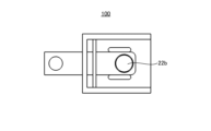
- FIG. 3 is a first schematic diagram showing the contact section 100 of the contact switch 1 according to the first embodiment.
- FIG. 4 is a second schematic diagram showing the contact section 100 of the contact switch 1 according to the first embodiment.
- FIG. 5 is a third schematic diagram showing the contact section 100 of the contact switch 1 according to the first embodiment.
- FIG. 6 is a perspective view showing the schematic configuration of the contact section 100 of the contact switch 1 according to the first embodiment.
- FIGS. 3, 4, 5, and 6 each show a schematic structure of the case cover 9, the movable contact 3b, the fixed contact 2b, the grid 11b, and the two insulators 121b, 122b.
- FIG. 4 is a schematic diagram of only the movable contact 3b, and in FIG. 4, the N direction is the longitudinal direction and the M direction is the lateral direction.
- FIG. 5 is a diagram of FIG. 3 without the movable contact 3b.
- FIG. 6 is a perspective view showing the state of FIG. 3 as viewed from the upper left.
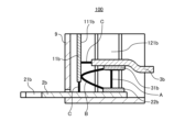
- FIG. 7 is a cross-sectional view showing a schematic cross-sectional structure of the contact section 100 of the contact switch 1 according to embodiment 1.
- FIG. 7 shows a schematic cross-sectional structure taken along line VII-VII in FIG. 3.
- FIG. 8 is a diagram showing the schematic configuration and operation flow of the contact section 100 of the contact switch 1 according to embodiment 1.
- the grid 11b is formed of a magnetic material such as iron.
- the grid 11b When the movable contact 31b and the fixed contact 22b come into contact with or separate from each other during energization, the grid 11b is characterized in that it forms a flow path that directs a portion of the hot gas flowing forward from the movable contact 31b or the fixed contact 22b to the side or rear of the movable contact 31b or the fixed contact 22b together with an arc that is generated between the movable contact 31b and the fixed contact 22b.
- the grid 11b has the function of changing the direction of flow of a portion of the hot gas and returning the hot gas to the fixed contact 22b and the movable contact 31b.
- the grid 11b is arranged on the longitudinal extension of the movable contactor 3b so that the front surface 111b of the grid 11b faces the movable contact 31b or the fixed contact 22b on most of its surface, and is characterized by having a length extending from above the upper surface of the movable contactor 3b to below the contact surface of the movable contact 31b with the fixed contact 22b at least when the movable contact 31b and the fixed contact 22b come into contact with or separate from each other.
- the front surface 111b of the grid 11b can change or reverse its direction of travel to the left or right when the generated hot gas collides with it.
- each of the grids 11b and 11e is a plate shape.
- the grid 11b does not necessarily have to be a single sheet, and even if multiple grids 11b are stacked in the longitudinal direction of the movable contactor 3b, i.e., in the front-to-rear direction, the same effect as that obtained when only one grid 11b is present can be obtained.
- the same effect as that obtained when only one grid 11b is present can be obtained as long as even one grid 11b is arranged so that the front surface 111b of the grid 11b faces the movable contact 31b or the fixed contact 22b on the longitudinal extension line of the movable contactor 3b and has a length from above the upper surface of the movable contactor 3b to below the contact surface of the movable contact 31b with the fixed contact 22b when the movable contact 31b and the fixed contact 22b come into contact with each other and are separated from each other.
- the present invention is not limited to this.
- the grid 11b is arranged so that the front surface 111b of the grid 11b faces the movable contact 31b or the fixed contact 22b over most of its surface, the grid 11b may have an inclination or a curved surface.
- Figure 9 is a cross-sectional view showing a schematic configuration of the contact portion 100 of the contact switch 1 according to the first embodiment.
- the grid 11b may have a structure in which the angle ⁇ is formed in the middle toward the movable contact 3b.
- the hot gas circulating through the return path X1 is more likely to return upward, which further enhances the arc cooling effect and the arc driving force, and the arc is quickly stretched toward the grid 11b, thereby quickly dividing the arc, and as a result, the arc interruption can be completed more quickly.
- the return path X1 will be described in detail later.
- the return path X1 is a hot gas flow path in the space having the movable contact 31b and the fixed contact 22b sandwiched between the two insulators 121b, 122b.
- the return path X1 is indicated by an arrow. Note that the return path X1 has been described as the space having the movable contact 31b and the fixed contact 22b sandwiched between the two insulators 121b, 122b, but is not limited to this. If there is a space at a position lower than the height of the side portion of the insulator 121b or insulator 122b on the side 91b or side 92b side of the case cover 9, that space may also be included in the return path X1.
- the insulator 121b is arranged between the movable contact 31b or the fixed contact 22b and the side surface 91b of the case cover 9 to form a return path X2 for returning hot gas generated when the movable contact 31b and the fixed contact 22b come into contact with and separate from each other to the fixed contact 22b and the movable contact 31b.
- the insulator 122b is arranged between the movable contact 31b or the fixed contact 22b and the side surface 92b of the case cover 9 to form a return path X3 for returning hot gas generated when the movable contact 31b and the fixed contact 22b come into contact with and separate from each other to the fixed contact 22b and the movable contact 31b.
- the return path X2 and the return path X3 are indicated by arrows. Both the return path X2 and the return path X3 are hot gas paths.
- the contact portion 100 constituting the second-phase arc-extinguishing chamber 10b further has a crossbar 8, as shown in FIG. 2.
- the opening/closing mechanism portion 110 constituting the second-phase arc-extinguishing chamber 10b further has a movable iron core 4, a fixed iron core 5, an operating coil 6, and a tripping spring 7, as shown in FIG. 2.
- the contact portion 100 and the opening/closing mechanism portion 110 are fixed with a screw 200.
- FIG. 7 is also a diagram showing the schematic configuration and operation flow of the contact section 100 of the contact switch 1 according to the first embodiment. Immediately after the movable contact 31b and the fixed contact 22b come into contact with each other, an arc A is generated that connects the movable contact 31b and the fixed contact 22b.
- the grid 11b can apply an electromagnetic force to the arc A in a direction from the movable contact 31b or the fixed contact 22b toward the front surface 111b of the grid 11b, and the arc A moves toward the front surface 111b of the grid 11b, and the shape of the arc A becomes a pulled shape like the arc B.
- the arc B attracted to the grid 11b comes into contact with the front surface 111b of the grid 11b, a current flows inside the grid 11b, and the arc B can be divided like the arc C.
- the arc interruption is completed.
- a portion of the hot gas flows into the return path X1, which is the direction from the movable contact 31b or the fixed contact 22b toward the grid 11b.
- the hot gas that collides with the front surface 111b of the grid 11b branches to the left and right.
- the hatched arrows in FIG. 8 indicate the left and right flows of the hot gas that collides with the front surface 111b of the grid 11b.
- the hot gas flows along the front surface 111b of the grid 11b, and eventually flows through the return path X2 and the return path X3 in the opposite direction to the hot gas in the return path X1.
- the hot gas does not necessarily have to branch at the front surface 111b of the grid 11b. Therefore, even if the hot gas is returned to at least one of the return paths X2 and X3, the same effect as that obtained when the hot gas branches at the front surface 111b of the grid 11b can be obtained.
- a part of the hot gas flowing through the return path X1 may reverse its direction of travel and return to the fixed contact 22b (not shown).
- the return path X1 uses the front surface 111b of the grid 11b as part of the return path, the return of the hot gas acts as a driving force to make the arc more likely to come into contact with the grid 11b, and the arc can be quickly stretched and broken, resulting in faster arc interruption.
- the hot gas returning through the return paths X2 and X3 flows into the fixed contact 22b from the rear after passing through the return paths. Therefore, by returning the hot gas, it is expected that the arc driving force will increase in the same direction as the electromagnetic force acting on the arc, and that the arc will be cooled.
- the contact switch 1 Focusing on the contact portion 100 constituting the second phase arc extinguishing chamber 10b, the contact switch 1 has a fixed contact 2b having a fixed contact 22b on its upper surface, and a movable contact 3b having a movable contact 31b that contacts the fixed contact 22b on its lower surface.
- the contact switch 1 is formed of a magnetic material, and further has a grid 11b that faces the movable contact 3b in the longitudinal direction of the movable contact 3b when the fixed contact 22b and the movable contact 31b are opened, is formed above the upper surface of the movable contact 3b, and is formed below the contact surface of the movable contact 31b with the fixed contact 22b.
- the contact switch 1 further has a case cover 9 located outside the fixed contact 2b, the movable contact 3b, and the grid 11b, and two insulators 121b, 122b located on the side of the movable contact 3b and that form a return path through which gas generated when the contact is opened flows in the gap between the case cover 9.
- the contact switch 1 may have only one of the two insulators 121b, 122b.
- the arc generated between the contacts can be moved in the direction of the grid 11b by electromagnetic force, and by circulating the hot gas generated together with the arc, the arc driving force can be increased in the same direction as the electromagnetic force acting on the arc, and a cooling effect on the arc can be expected. Furthermore, by using the front surface 111b of the grid 11b as part of the circulation path, the circulation of the hot gas serves as a driving force to make the arc more likely to come into contact with the grid 11b, and the arc can be quickly stretched and broken, and as a result, arc interruption can be completed more quickly. In other words, the contact switch 1 according to the first embodiment can improve the performance of interrupting the arc generated when the contacts are opened.
- FIG. 10 is a diagram showing a schematic configuration of a contact portion 100 of a contact switch according to a second embodiment.
- FIG. 10 shows the flow of gas in the contact portion 100 according to the second embodiment.
- the second embodiment is characterized in that the gas outflow surface d of the return path is smaller than the gas inflow surface e of the return path.
- the return paths are the return paths X2 and X3.
- the insulators 121b and 122b are arranged so that the insulator 121b is inclined with respect to the side surface 91b of the case cover 9 and the insulator 122b is inclined with respect to the side surface 92b of the case cover 9.
- the gas outflow surface d is smaller than the gas inflow surface e.
- the hatched arrows in FIG. 10 indicate the leftward and rightward flows of the hot gas that has collided with the front surface 111b of the grid 11b.
- the insulators 121b, 122b are inclined relative to the side surfaces 91b, 92b of the case cover 9 as a structure in which the gas outflow surface d is smaller than the gas inflow surface e, but this is not limited thereto, and the insulators 121b, 122b may be structured such that the gas outflow surface d is smaller than the gas inflow surface e.
- the insulators 121b, 122b may be structured to have an inclination in the vertical direction, and the height from the gas inflow surface e to the gas outflow surface d may gradually decrease so that the gas outflow surface d is smaller than the gas inflow surface e.
- the size of the gas outflow surface d of the return flow path X2 and the size of the gas outflow surface d of the return flow path X3 do not necessarily need to be the same, and the size of the gas inflow surface e of the return flow path X2 and the gas inflow surface e of the return flow path X3 do not need to be the same either.
- the return flow path X2 or the return flow path X3 may be formed so that at least the upper or lower direction is covered with an insulator, and may be structured to prevent hot gas from flowing out in the upward or downward direction, and may include a structure in which the insulator covering the return flow path X2 or the return flow path X3 is inclined in the vertical direction so that the gas outflow surface d is smaller than the gas inflow surface e.
- the gas outlet surface d of the return flow path is smaller than the gas inlet surface e of the return flow path, so that it is possible to prevent backflow of hot gas inside the return flow path and to increase the flow rate of hot gas from the gas outlet surface d.
- the return flow efficiency is increased, the flow rate at which hot gas is blown onto the movable contact 31b and the fixed contact 22b is increased, the arc cooling effect and the arc driving force are further increased, and the arc can be quickly stretched and cut off to the grid 11b, so that the arc interruption can be completed more quickly.
- the return paths are the return path X2 and the return path X3. Note that the gas outlet surface d may be smaller than the gas inlet surface e in one of the return paths X2 and X3.
- Fig. 11 is a schematic diagram of a contact section 100 of a contact switch according to embodiment 3.
- Fig. 12 is a cross-sectional view showing a cross-sectional structure of a contact section 100 of a contact switch according to embodiment 3.
- Fig. 12 shows a cross-sectional structure and a gas flow taken along line XII-XII in Fig. 11.
- embodiment 3 is characterized in that an insulator 123b is disposed in a position in the moving direction of the movable contactor 3b, more specifically, in an upward position, so as to face the grid 11b.
- the insulator 123b is disposed on the movable contact 31b side as viewed from the grid 11b, and is disposed in a position above the upper surface of the movable contactor 3b in the moving direction of the movable contactor 3b, so as to face the grid 11b.
- part of the hot gas that is generated along with the arc between the movable contact 31b and the fixed contact 22b flows in the direction from the movable contact 31b or the fixed contact 22b toward the grid 11b.
- the hot gas that collides with the front surface 111b of the grid 11b branches in the left and right directions, but as shown in Figure 12, part of the hot gas that collides with the front surface 111b of the grid 11b does not branch in the left and right directions, but instead turns around toward the movable contact 31b and the fixed contact 22b and flows further up the return path X4 of the movable contactor 3b.
- the return path X4 is indicated by an arrow.
- the contact unit 100 can divert the hot gas flowing through the return path X4 to the return path X5 in the left-right direction of the movable contact 3b.
- the return path X5 is indicated by an arrow.
- the insulators 121b and 122b have a stepped shape with the grid 11b side lower so that the hot gas branched by the insulator 123b can easily flow into the return paths X2 and X3.
- the return path X4 is a path surrounded by the grid 11b, the insulators 121b and 122b, the case cover 9, and the upper surface of the movable contact 3b.
- the return path X5 is a path that branches the hot gas by the insulator 123b in the direction of the return path X2 and the return path X3.
- the hot gas does not necessarily have to be branched at the insulator 123b. Therefore, even if the flow direction of the hot gas is changed by the insulator 123b and the hot gas is returned to at least one of the return paths X2 and X3, the same effect can be obtained as when the hot gas is branched at the insulator 123b and returned to both the return paths X2 and X3.
- the insulator 123b has a linear shape parallel to the grid 11b, but is not limited to this.
- the shape of the insulator 123b may be inclined in the direction of the return path X2 or the return path X3, or may have a convex portion in the direction of the grid 11b.
- Gas blowing port 131b is provided on the gas outlet side of return flow path X2, and gas blowing port 132b is provided on the gas outlet side of return flow path X3, so that return flow path X6 is added to the space between insulator 121b and gas blowing port 131b, and return flow path X7 is added to the space between insulator 122b and gas blowing port 132b.
- Return flow path X6 and return flow path X7 are indicated by arrows.
- the fourth embodiment can efficiently spray hot gas onto the movable contact 31b and the fixed contact 22b, improving the arc cooling effect and more reliably completing the arc interruption.
- Grid 11b may be configured with a connection structure of a plurality of separately arranged members.
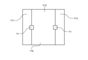
- FIG. 20 is a schematic diagram showing a first example of grid 11b configured with a connection structure of a contact switch according to embodiment 6. As shown in FIG. 20, grid 11b of the first example having through hole Y1 is configured with three members Y11, Y12, and Y13.
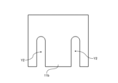
- FIG. 21 is a schematic diagram showing a second example of grid 11b configured with a connection structure of a contact switch according to embodiment 6. As shown in FIG. 21, grid 11b of the second example having slit Y2 is configured with three members Y21, Y22, and Y23.
Landscapes
- Arc-Extinguishing Devices That Are Switches (AREA)
Priority Applications (2)
| Application Number | Priority Date | Filing Date | Title |
|---|---|---|---|
| PCT/JP2023/041240 WO2025104866A1 (ja) | 2023-11-16 | 2023-11-16 | 接点開閉器 |
| JP2024519442A JP7774721B2 (ja) | 2023-11-16 | 2023-11-16 | 接点開閉器 |
Applications Claiming Priority (1)
| Application Number | Priority Date | Filing Date | Title |
|---|---|---|---|
| PCT/JP2023/041240 WO2025104866A1 (ja) | 2023-11-16 | 2023-11-16 | 接点開閉器 |
Publications (1)
| Publication Number | Publication Date |
|---|---|
| WO2025104866A1 true WO2025104866A1 (ja) | 2025-05-22 |
Family
ID=95742340
Family Applications (1)
| Application Number | Title | Priority Date | Filing Date |
|---|---|---|---|
| PCT/JP2023/041240 Pending WO2025104866A1 (ja) | 2023-11-16 | 2023-11-16 | 接点開閉器 |
Country Status (2)
| Country | Link |
|---|---|
| JP (1) | JP7774721B2 (https=) |
| WO (1) | WO2025104866A1 (https=) |
Citations (5)
| Publication number | Priority date | Publication date | Assignee | Title |
|---|---|---|---|---|
| JPS6064545U (ja) * | 1983-10-11 | 1985-05-08 | 松下電工株式会社 | 消弧装置 |
| JPH0527935U (ja) * | 1991-09-18 | 1993-04-09 | 三菱電機株式会社 | 消弧装置 |
| JPH05135680A (ja) * | 1991-11-11 | 1993-06-01 | Matsushita Electric Works Ltd | 消弧装置 |
| JPH07272597A (ja) * | 1994-03-31 | 1995-10-20 | Mitsubishi Electric Corp | 開閉器 |
| JPH11353967A (ja) * | 1998-06-09 | 1999-12-24 | Mitsubishi Electric Corp | 開閉器 |
Family Cites Families (3)
| Publication number | Priority date | Publication date | Assignee | Title |
|---|---|---|---|---|
| JPH0745870Y2 (ja) * | 1989-09-26 | 1995-10-18 | 松下電工株式会社 | 消弧装置 |
| JPH0485552U (https=) * | 1990-11-29 | 1992-07-24 | ||
| JPH0643992U (ja) * | 1992-11-24 | 1994-06-10 | 松下電工株式会社 | 回路遮断器 |
-
2023
- 2023-11-16 WO PCT/JP2023/041240 patent/WO2025104866A1/ja active Pending
- 2023-11-16 JP JP2024519442A patent/JP7774721B2/ja active Active
Patent Citations (5)
| Publication number | Priority date | Publication date | Assignee | Title |
|---|---|---|---|---|
| JPS6064545U (ja) * | 1983-10-11 | 1985-05-08 | 松下電工株式会社 | 消弧装置 |
| JPH0527935U (ja) * | 1991-09-18 | 1993-04-09 | 三菱電機株式会社 | 消弧装置 |
| JPH05135680A (ja) * | 1991-11-11 | 1993-06-01 | Matsushita Electric Works Ltd | 消弧装置 |
| JPH07272597A (ja) * | 1994-03-31 | 1995-10-20 | Mitsubishi Electric Corp | 開閉器 |
| JPH11353967A (ja) * | 1998-06-09 | 1999-12-24 | Mitsubishi Electric Corp | 開閉器 |
Also Published As
| Publication number | Publication date |
|---|---|
| JPWO2025104866A1 (https=) | 2025-05-22 |
| JP7774721B2 (ja) | 2025-11-21 |
Similar Documents
| Publication | Publication Date | Title |
|---|---|---|
| KR100963738B1 (ko) | 회로 차단기 | |
| EP2980821B1 (en) | Switchgear | |
| JP6516078B1 (ja) | 回路遮断器及び回路遮断方法 | |
| WO2001027950A1 (en) | Contactor | |
| KR101670567B1 (ko) | 전자 개폐기 | |
| KR20220147380A (ko) | 아크 소호부 및 이를 포함하는 기중 차단기 | |
| KR910000071B1 (ko) | 개폐기 | |
| CN101625934A (zh) | 电路断路器 | |
| JP7774721B2 (ja) | 接点開閉器 | |
| JPWO2012157057A1 (ja) | 開閉器 | |
| JP2010251299A (ja) | 回路遮断器 | |
| TW200409160A (en) | Electromagnetic contactor | |
| JP2011014350A (ja) | 回路遮断器 | |
| CN112840429B (zh) | 触点开闭器 | |
| JP6574618B2 (ja) | 回路遮断器 | |
| JP2008226632A (ja) | 回路遮断器 | |
| WO2024218863A1 (ja) | 開閉器 | |
| JP2006059758A (ja) | 回路遮断器の消弧装置 | |
| JP5054052B2 (ja) | 開閉器 | |
| CN116130313A (zh) | 一种灭弧结构及断路器 | |
| JP2009070601A (ja) | 回路遮断器 | |
| CN114600219A (zh) | 能够有效地消灭电弧的电磁接触器 | |
| CN102856135A (zh) | 双断保护开关设备 | |
| JP6345369B2 (ja) | 開閉器 | |
| JP7616100B2 (ja) | 開閉器 |
Legal Events
| Date | Code | Title | Description |
|---|---|---|---|
| ENP | Entry into the national phase |
Ref document number: 2024519442 Country of ref document: JP Kind code of ref document: A |
|
| WWE | Wipo information: entry into national phase |
Ref document number: 2024519442 Country of ref document: JP |
|
| 121 | Ep: the epo has been informed by wipo that ep was designated in this application |
Ref document number: 23958872 Country of ref document: EP Kind code of ref document: A1 |