WO2025100461A1 - ルーパー設備、熱延板酸洗設備および熱延板酸洗方法 - Google Patents
ルーパー設備、熱延板酸洗設備および熱延板酸洗方法 Download PDFInfo
- Publication number
- WO2025100461A1 WO2025100461A1 PCT/JP2024/039518 JP2024039518W WO2025100461A1 WO 2025100461 A1 WO2025100461 A1 WO 2025100461A1 JP 2024039518 W JP2024039518 W JP 2024039518W WO 2025100461 A1 WO2025100461 A1 WO 2025100461A1
- Authority
- WO
- WIPO (PCT)
- Prior art keywords
- looper
- hot
- steel plate
- pickling
- rolled sheet
- Prior art date
- Legal status (The legal status is an assumption and is not a legal conclusion. Google has not performed a legal analysis and makes no representation as to the accuracy of the status listed.)
- Pending
Links
Images






Classifications
-
- B—PERFORMING OPERATIONS; TRANSPORTING
- B21—MECHANICAL METAL-WORKING WITHOUT ESSENTIALLY REMOVING MATERIAL; PUNCHING METAL
- B21B—ROLLING OF METAL
- B21B45/00—Devices for surface or other treatment of work, specially combined with or arranged in, or specially adapted for use in connection with, metal-rolling mills
- B21B45/02—Devices for surface or other treatment of work, specially combined with or arranged in, or specially adapted for use in connection with, metal-rolling mills for lubricating, cooling, or cleaning
-
- B—PERFORMING OPERATIONS; TRANSPORTING
- B21—MECHANICAL METAL-WORKING WITHOUT ESSENTIALLY REMOVING MATERIAL; PUNCHING METAL
- B21C—MANUFACTURE OF METAL SHEETS, WIRE, RODS, TUBES, PROFILES OR LIKE SEMI-MANUFACTURED PRODUCTS OTHERWISE THAN BY ROLLING; AUXILIARY OPERATIONS USED IN CONNECTION WITH METAL-WORKING WITHOUT ESSENTIALLY REMOVING MATERIAL
- B21C49/00—Devices for temporarily accumulating material
-
- C—CHEMISTRY; METALLURGY
- C23—COATING METALLIC MATERIAL; COATING MATERIAL WITH METALLIC MATERIAL; CHEMICAL SURFACE TREATMENT; DIFFUSION TREATMENT OF METALLIC MATERIAL; COATING BY VACUUM EVAPORATION, BY SPUTTERING, BY ION IMPLANTATION OR BY CHEMICAL VAPOUR DEPOSITION, IN GENERAL; INHIBITING CORROSION OF METALLIC MATERIAL OR INCRUSTATION IN GENERAL
- C23G—CLEANING OR DE-GREASING OF METALLIC MATERIAL BY CHEMICAL METHODS OTHER THAN ELECTROLYSIS
- C23G1/00—Cleaning or pickling metallic material with solutions or molten salts
- C23G1/02—Cleaning or pickling metallic material with solutions or molten salts with acid solutions
- C23G1/08—Iron or steel
-
- C—CHEMISTRY; METALLURGY
- C23—COATING METALLIC MATERIAL; COATING MATERIAL WITH METALLIC MATERIAL; CHEMICAL SURFACE TREATMENT; DIFFUSION TREATMENT OF METALLIC MATERIAL; COATING BY VACUUM EVAPORATION, BY SPUTTERING, BY ION IMPLANTATION OR BY CHEMICAL VAPOUR DEPOSITION, IN GENERAL; INHIBITING CORROSION OF METALLIC MATERIAL OR INCRUSTATION IN GENERAL
- C23G—CLEANING OR DE-GREASING OF METALLIC MATERIAL BY CHEMICAL METHODS OTHER THAN ELECTROLYSIS
- C23G3/00—Apparatus for cleaning or pickling metallic material
Definitions
- the present invention relates to a looper system, and a hot-rolled strip pickling system and a hot-rolled strip pickling method using such a looper system.
- looper equipment In order to continuously perform various treatments on steel sheets, looper equipment is used to transport the steel sheets while storing them at an appropriate length. For example, when performing pickling treatment on thin steel sheets with a thickness of a few mm or less on a continuous line, the tail end of the preceding steel sheet and the front end of the following steel sheet are first welded by a welding device, and then the steel sheets are fed to the pickling device via an annealing furnace and a cooling zone, and pickling treatment is continuously performed on the steel sheets. In this case, the steel sheet is stopped from passing during welding, but is passed through during pickling for continuous treatment, so the amount of steel sheet (passing length) between the welding device on the upstream side of the line and the pickling device on the downstream side changes from time to time. Therefore, a looper equipment that can adjust the amount of steel sheet stored is installed between such an upstream device and a downstream device, which makes it possible to continuously treat the steel sheets.
- the platform 5 on one side in the width direction of the steel plate 2 and the platform 5 on the other side each rotatably support one end and the other end of a conveying roll 3 having a rotation axis extending in the width direction of the steel plate 2.
- the steel plate 2 advances into the depths of the paper in Fig. 1A while being fed by the multiple conveying rolls 3 within the concave conveying area and below the looper car.
- Patent Document 1 discloses a technology that reduces tension deviation and prevents meandering of the metal strip by adjusting the roll drive control inside the looper.
- Patent Document 2 discloses a technique for correcting the shape of hot-rolled steel sheet by pressing it with a roll after pickling.
- Patent document 3 discloses a technology that prevents the steel strip from meandering by adjusting the control unit of the steering roll.
- Patent document 4 discloses a technology for preventing meandering in a metal strip winding device by installing side guides on the sides and pressing the metal strip from above with rolls.
- the above-mentioned conventional techniques are intended to straighten the shape of a steel sheet or suppress meandering of the steel sheet.
- the above-mentioned conventional techniques have some concerns, such as a small tension adjustment margin for preventing breakage of the steel sheet, the possibility of deformation or breakage of the steel sheet due to excessive straightening of the shape, and the difficulty of pressing down the steel sheet over the entire length of the looper.
- a limit to straightening the shape of the steel sheet and suppressing meandering and there are cases where the steel sheet still significantly meanders even with the above-mentioned conventional techniques.
- the side of the steel plate transported through the looper equipment may come into contact with the wall of the equipment, etc., causing a defect (guide defect) similar to rubbing on the side of the steel plate, resulting in a loss of yield.
- these guide scratches are one of the main causes of production defects, for example in continuous pickling lines for steel sheets, and can even lead to the breakage of the steel sheet during the pickling line. Furthermore, if a steel sheet with guide scratches is directly supplied to the next processing step, for example a cold rolling machine, the steel sheet can break at high speed during the cold rolling line, causing severe damage. Therefore, when continuously applying the desired processing to steel sheets, it is important to store and transport the steel sheets while suppressing guide scratches.
- the present invention has been made in consideration of the above-mentioned circumstances, and has an object to provide a looper equipment that can suppress the occurrence of defects in a steel sheet even when the steel sheet being transported on a continuous processing line significantly meanders to the extent that it comes into contact with the looper equipment.
- Another object of the present invention is to provide a hot-rolled sheet pickling facility and a hot-rolled sheet pickling method that use such looper equipment to continuously pickle a hot-rolled sheet while suppressing the occurrence of defects in the hot-rolled sheet.
- the present inventors have thoroughly studied the causes of defects occurring in a steel sheet due to contact of the steel sheet with the looper equipment during transportation.
- a part of the steel sheet 2 transported in the looper equipment 1 has a defective shape
- the transport direction of the steel sheet 2 starts to locally deviate from the longitudinal direction, and as the transport continues, the deviation gradually increases, causing a noticeable meandering of the steel sheet 2.
- the inventors have found that the contact of the meandering steel sheet 2 with the stand 5, particularly with the stand leg 51, causes guide defects in the steel sheet 2.
- the inventors further investigated a structure capable of preventing a steel plate from coming into contact with the rack even if the steel plate is meandering while being transported within the looper equipment, and completed the present invention.
- a looper facility capable of storing and transporting steel plates in a longitudinal direction, A plurality of conveying rolls are provided at intervals in the longitudinal direction so that their rotation axes extend in the width direction of the steel plate, and support one side of the steel plate; At least one fixed roll provided at one end in the longitudinal direction; A stand is provided on both sides of the steel plate in the width direction and extending in the longitudinal direction; At least one looper parker is provided at the other end in the longitudinal direction and is capable of adjusting the amount of the steel plate stored by moving along the frame, a pair of vertical rolls each having a rotation axis extending in the thickness direction of the steel plate and rotatable along the conveying direction of the steel plate, the pair of vertical rolls being provided at a position sandwiching the steel plate in the width direction and at a position where the distance from the steel plate is smaller than the distance between the steel plate and the frame, the pair of vertical rolls having a rotation axis extending in the thickness direction of
- the vertical roll is supported by a bearing
- the looper equipment according to the above-mentioned [1] further comprises a guard for covering a gap between a bottom surface of the vertical roll and the bearing.
- the steel sheet is a hot-rolled sheet for an electromagnetic steel sheet
- a pickling device capable of pickling the hot-rolled sheet is provided downstream in the conveying direction of the looper facility according to any one of [1] to [3] above,
- the hot-rolled sheet pickling facility is configured so that the hot-rolled sheet can be supplied to the pickling device via the looper facility.
- the steel sheet is a hot-rolled sheet for manufacturing an electromagnetic steel sheet
- a hot-rolled sheet pickling method comprising the steps of: supplying the hot-rolled sheet through the looper facility according to any one of the above items [1] to [3] to a pickling device provided downstream of the looper facility in the conveying direction, thereby subjecting the hot-rolled sheet to a pickling treatment.
- the present invention it is possible to provide a looper equipment that can effectively reduce the occurrence of defects in a steel sheet even if the transported steel sheet meanders to the extent that it comes into contact with the looper equipment. Furthermore, according to the present invention, it is possible to provide a hot-rolled sheet pickling system and a hot-rolled sheet pickling method capable of continuously pickling a hot-rolled sheet while effectively reducing the occurrence of defects in the hot-rolled sheet.
- the present invention is particularly useful for thin steel plates having a thickness of 2.7 mm or less.
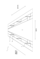
- FIG. 1 is a schematic perspective view showing a part of a typical looper system when a steel sheet is being normally transported.
- FIG. 1 is a schematic perspective view showing a part of a general looper installation in which a steel sheet meanders.
- FIG. 1 is a schematic side view showing a typical looper system.
- FIG. 2 is a side schematic view showing an example of the looper equipment of the present invention.
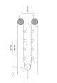
- FIG. 2 is a plan view showing the position of vertical rolls in one embodiment of the present invention.
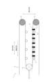
- FIG. 11 is a schematic plan view showing the position of vertical rolls in another embodiment of the present invention.
- FIG. 11 is a schematic plan view showing the position of vertical rolls in another embodiment of the present invention.
- FIG. 2 is a side view schematic diagram showing a vertical roll in one embodiment of the present invention.
- FIG. 2 is a front schematic view showing a vertical roll in one embodiment of the present invention.
- FIG. 2 is a schematic plan view showing a vertical roll in one embodiment of the present invention.
- FIG. 1 is a side schematic view showing an example of a hot-rolled strip pickling facility of the present invention.
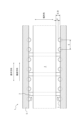
- FIG. 2 is a schematic plan view showing various changes in the installation interval between vertical rolls in the examples. 1 is a graph showing the results of Example 2.
- the looper equipment of the present invention is capable of storing and transporting a steel sheet in a longitudinal direction, and includes a plurality of transport rolls, at least one fixed roll, a frame, at least one looper car, and one or more pairs of vertical rolls provided at specific positions.
- the looper equipment of the present invention may have any other configuration in addition to the above configuration. Since the looper equipment of the present invention has the above-mentioned configuration, particularly the vertical rolls, it is possible to continuously apply a desired processing to a steel sheet while effectively suppressing the occurrence of guide scratches on the steel sheet, regardless of, for example, fluctuations in the amount of steel sheet accumulated (passing length), conveying direction, and conveying speed between the welding device and the processing device.
- FIGS 1A and 1B are perspective views of a general looper apparatus as seen from the front and diagonally above, i.e., the front side in the conveying direction
- Figure 2 is a side view of the general looper apparatus as seen from one side in the width direction of the steel sheet.
- the looper equipment 1 has an arbitrary number of conveying rolls (also called table rolls, or called horizontal rolls when the steel plate is conveyed horizontally) 3.
- Each conveying roll 3 is provided so that its rotation axis extends in the width direction of the steel plate 2.
- the conveying rolls 3 are provided at an arbitrary interval in the longitudinal direction, for example, about 3 m apart.
- the conveying rolls 3 support one side of the steel plate 2, or the lower side when the steel plate is conveyed horizontally, while rotating along the conveying direction of the steel plate 2, thereby conveying the steel plate 2.
- the looper equipment 1 also has at least one fixed roll (also called a steering roll) 4 provided at one end in the longitudinal direction, and at least one looper (the figure mainly shows a looper roll) 6 provided at the other end in the longitudinal direction.
- the pedestals 5 are provided on both sides of the width of the steel plate 2, extending in the longitudinal direction. Referring also to Fig. 4, the pedestals 5 are usually provided so as to sandwich the steel plate 2, which is normally transported, in the width direction at an arbitrary distance D.
- the greater the distance D the less likely the meandering steel plate will collide with the pedestals, so the distance D is preferably 150 mm or more. If the distance D is too large, the width of the steel plate will be narrowed, resulting in a decrease in production capacity per unit time, so the distance D is preferably 370 mm or less.
- the frame 5 may be supported by frame legs 51 arranged at any interval in the longitudinal direction, so that the rail portion of the frame 5 can be arranged at a height equal to the height of the frame legs 51 above the bottom surface of the looper equipment.
- the arbitrary distance D1 between the frame legs 51 and the steel plate 2 is usually the same as the above-mentioned distance D between the frame 5 and the steel plate 2, and the preferred range of distance D1 is also the same as that for the distance D of the frame 5.
- the steel plate 2 is usually transported at a height between the height of the transport rolls 3 and the height of the frame 5 or the frame legs 51.
- the looper equipment further has one or more pairs of vertical rolls at positions sandwiching the width direction of the steel sheet.
- a pair of vertical rolls 7 can be provided on one side of a stand 5 in the width direction of the steel sheet 2 and on the other side of a stand 5 so as to face each other in the width direction of the steel sheet 2.
- the vertical rolls 7 may be paired at positions sandwiching the width direction of the steel sheet 2 with an arbitrary distance shifted in the longitudinal direction, for example, as shown in Fig. 5.
- the vertical rolls 7 are also provided at a position where the distance d from the steel plate 2 is smaller than the distance D between the steel plate 2 and the frame 5, that is, so as to satisfy the relationship D>d.
- the vertical rolls 7 are also provided at a position where the distance D1 from the steel plate 2 to the frame leg 51 satisfies the relationship D1>d.
- the distance D (or D1) refers to the distance between the normally transported steel plate 2 and the stand 5 (or stand leg 51) in the width direction (horizontal) of the steel plate as viewed from one side in the thickness direction of the steel plate (see FIG. 4).
- the distance d refers to the distance between the normally transported steel plate 2 and the vertical rolls 7 in the width direction (horizontal) of the steel plate as viewed from one side in the thickness direction of the steel plate (see FIG. 4).
- the vertical rolls 7 are provided so that the outer circumferential surface of the vertical rolls is located inside the transport area further inside than the stand 5 including the stand leg 51.
- the penetration length (D-d) of the vertical rolls into the inside of the conveying region is preferably 10 mm or more, more preferably 30 mm or more. If the penetration length of the vertical rolls is shorter than the above lower limit, the possibility that the steel sheet will come into contact with the frame when the steel sheet meanders increases.
- the penetration length is preferably (width of conveying region-maximum width of steel sheet) x (1/20) or less.
- the width of the transport area is the distance between one stand in the width direction of the steel plate and the other stand in the width direction.
- the recessed length is preferably D ⁇ (1/10) or less.
- the intrusion length (D1-d) of the vertical rolls into the conveying area of the frame legs 51 is preferably 10 mm or more, and more preferably 30 mm or more.
- the vertical rolls may be provided with different penetration lengths in the longitudinal and/or width directions, as shown in FIG. 6, for example.
- the penetration length of the vertical roll at that location it is preferable to set the penetration length of the vertical roll at that location to be longer than the penetration length at other locations. From this perspective, it is preferable to set the penetration length of the vertical roll at that location (D-d) to 30 mm or more, and it is even more preferable to set (D1-d) to 30 mm or more.
- the vertical rolls 7 have a rotation axis extending in the thickness direction of the steel sheet 2 and are rotatable along the conveying direction of the steel sheet.
- the vertical rolls 7 rotate to help the steel sheet 2 continue to be conveyed. This reliably reduces the frictional force on the steel sheet when it comes into contact with the looper equipment, and suppresses the occurrence of defects on the steel sheet.
- the shape of the vertical roll is preferably cylindrical.
- the vertical rolls 7 are preferably supported by the frame 5. By supporting the vertical rolls on each of the frames on both sides of the width of the steel plate, the vertical rolls can be fixed well and contact of the steel plate with the frame can be more effectively suppressed.
- the vertical rolls 7 can be installed in two or more pairs at any interval S along the longitudinal direction (conveying direction) of the steel sheet 2.
- the installation interval S of the vertical rolls 7 is not particularly limited as long as the adjacent vertical rolls do not come into contact with each other and their rotation is not hindered. Therefore, the lower limit of the installation interval S of the vertical rolls 7 can be set to be greater than the diameter of the vertical rolls (i.e., the gap between the adjacent vertical rolls is greater than 0 m) when the diameters of the adjacent vertical rolls are equal, for example.
- the installation interval S of the vertical rolls 7 is preferably 2.0 m or more, and more preferably greater than 2.5 m.
- the installation interval S of the vertical rolls refers to the distance in the longitudinal direction between the rotation axes of one vertical roll and the other vertical roll adjacent to each other in the longitudinal direction (see Figs. 4 and 5).
- the installation interval S of the vertical rolls 7 is widened, the possibility of the meandering steel sheet 2 coming into contact with the frame 5 increases. According to the inventors' study, meandering of the steel sheet is relatively likely to occur at the longitudinal ends. If this steel sheet end comes into contact with the frame and a flaw occurs, the defective end can be cut off prior to the next process (e.g., the cold rolling process). In this way, the upper limit of the installation interval S of the vertical rolls 7 can be determined from the length that is allowable in each process for the occurrence of flaws in the steel sheet and the amount of cutting caused by them. From this perspective, the installation interval S of the vertical rolls 7 is preferably 10 m or less, more preferably less than 7.5 m, and even more preferably 5 m or less.
- meandering of the steel sheet is relatively likely to occur at the longitudinal end portion. More specifically, according to the findings by the inventors, meandering of the steel sheet is likely to start between the exit side of the fixed roll and the first transport roll. In addition, when a welding device is provided upstream of the looper system, the steel sheet is likely to meander near the welding device.
- the pair of vertical rolls 7 located at the most upstream in the conveying direction are preferably provided between the fixed roll 4 and the conveying roll 3 located at the most upstream, as exemplified in Fig. 3, and more preferably provided at a position closer to the conveying roll 3 than the fixed roll 4. This makes it possible to efficiently suppress the occurrence of meandering at the inlet side of the looper facility.
- the vertical roll is preferably supported by a bearing.
- one end of the vertical roll 7 in the direction of the rotation axis is rotatably supported by a bearing 71, and the bearing 71 can be installed, for example, on the floor surface of the conveying area in the looper equipment.
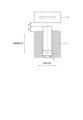
- FIG. 7A shows a side view of the vertical roll 7 and the bearing 71 as seen from one side in the width direction of the steel plate.
- FIG. 7B shows a front view of these as seen from the front side in the conveying direction of the steel plate, and a stand can be located on the right side of the paper in FIG. 7B, and a steel plate can be located on the left side of the paper.
- FIG. 7A shows a side view of the vertical roll 7 and the bearing 71 as seen from one side in the width direction of the steel plate.
- FIG. 7B shows a front view of these as seen from the front side in the conveying direction of the steel plate, and a stand can be located on the right side of the paper in FIG. 7B,
- FIG. 7C shows a plan view of these as seen from one side of the surface of the steel plate, and a stand can be located on the right side of the paper in FIG. 7C, and a steel plate can be located on the left side of the paper.
- the rotation axis of the vertical roll 7 and the center line of the bearing 71 are usually on the same line, and therefore the suitable installation position of the bearing 71 can follow the suitable installation position for the vertical roll 7 described above. This allows the vertical roll to be firmly fixed at a predetermined position in the looper equipment, and the occurrence of guide scratches in the steel plate conveyed in the looper equipment can be effectively prevented.
- the material of the vertical roll is preferably a material that is not easily worn when in contact with the steel sheet and is not easily scratched when in contact, and more preferably a metal having heat resistance and wear resistance. From the viewpoint of excellent wear resistance, chrome steel is more preferable.
- An example of a composition of the vertical roll that is preferably used contains Cr: 1.30% to 1.60%. It is more preferable to further contain one or two of C: 0.95% to 1.10% and Si: 0.15% to 0.35%. It is more preferable to further contain one or more selected from the group consisting of Mn: more than 0% and 0.50% or less, P: more than 0% and 0.025% or less, and S: more than 0% and 0.025% or less. There is no particular limitation, and the balance can be Fe and unavoidable impurities. Here, the above percentages are mass percentages.
- the suitable material for the bearing can also follow the vertical roll.
- the size of the vertical roll is preferably such that it does not interfere with the looper car; the stand including the stand legs and looper rails; and the steel plate being transported normally.
- the diameter of the vertical roll is preferably 50 mm or more and 150 mm or less.
- the height of the vertical rolls is preferably a height that can sufficiently cover the expected range of heights at which the steel sheet may meander, for example, the range of heights at which interference marks with the steel sheet have been confirmed in a preliminary study.
- the height of the vertical rolls is preferably 170 mm or more and 300 mm or less.
- looper cars usually move along the frame. Therefore, it is preferable to set the upper limit of the height of the vertical rolls in the rotation axis direction to a position lower than the lower limit of the height of the looper car moving on the frame rail in the rotation axis direction.
- the downward separation distance d2 of the vertical rolls 7 from the looper car 6 is arbitrary, but from the viewpoint of more reliably avoiding the interference of the looper car 6 with the vertical rolls 7, it is preferable to set d2 in the range of more than 0 mm and not more than 100 mm.
- the vertical roll 7A for example, when the vertical roll 7 is supported by the frame 5 (i.e., the frame is the support member), it is preferable to set the upward separation distance d3 of the vertical roll 7 from the frame 5 to more than 0 mm, and more preferably to 3 mm or more. Therefore, the preferred range of the height of the vertical roll in the direction of the rotation axis of the vertical roll can be above the upper limit of the height of the stand 5 and below the lower limit of the height of the looper car (both d2 and d3 are greater than 0 mm).
- a gap may be generated between the vertical rolls 7 and the bearings 71 due to the structure.
- the meandering steel sheet may enter the gap, causing serious defects in the steel sheet.
- the above problem may occur when using a thin steel sheet having a thickness of 2.7 mm or less and/or a steel sheet having a so-called edge stretch, in which a wavy shape defect occurs at the width direction end of the steel sheet.
- the guard preferably has a height and thickness sufficient to cover the gap.
- the shape of the guard is not particularly limited, and may be formed on a plate-like side surface of a rectangular prism such as a square prism as exemplified in Fig. 7C, or may be formed on a side surface of a cylinder having an arc-shaped cross section along the outer periphery of the vertical roll 7.
- the method of installing the guard is not particularly limited as long as it does not hinder the rotation of the vertical roll, and for example, the guard can be supported by the wall surface of the frame.
- the vertical roll 7 and the bearing 71 are provided in the space of the guard 72 toward the steel plate (not shown) being transported on the left side of the drawing so that the guard 72 is supported by the wall surface (not shown) of the frame on the right side of the drawing. In this way, by providing the looper equipment with an additional guard, it is possible to avoid or reduce serious defects caused by the steel sheet getting stuck in the gap between the vertical roll and the bearing.
- the side of the steel plate comes into contact with the vertical rolls instead of interfering with equipment such as a frame or a wall.
- the vertical rolls rotate in the same direction as the conveying direction, mitigating the impact on the side of the steel plate. In this way, it is possible to effectively prevent defects (guide scratches) from occurring on the side.
- the looper equipment may have other components in addition to the components described above, as long as the effects of the present invention are not impaired.
- the other components are not particularly limited, and examples thereof include a surveillance camera, various control devices, and detectors.
- the steel sheet is a hot-rolled sheet for an electromagnetic steel sheet
- a pickling device capable of pickling the hot-rolled sheet is further provided downstream in the conveying direction of the above-mentioned looper equipment, and the hot-rolled sheet is supplied to the pickling device via the above-mentioned looper equipment.
- the steel sheet is a hot-rolled sheet for manufacturing an electromagnetic steel sheet
- the hot-rolled sheet is subjected to pickling treatment by supplying the hot-rolled sheet via the above-mentioned looper equipment to a pickling device provided downstream of the looper equipment in the conveying direction.
- the hot-rolled strip pickling equipment and the hot-rolled strip pickling method of the present invention may further include other devices and other steps, respectively.
- the hot-rolled strip pickling plant and the hot-rolled strip pickling method of the present invention utilize the above-mentioned looper plant, and therefore can obtain the same effects as those obtained by the looper plant of the present invention. Therefore, the defect rate in the looper plant can be reduced, and the hot-rolled strip can be pickled continuously and satisfactorily with a high yield.
- Hot-rolled sheet pickling equipment and hot-rolled sheet pickling method of the present invention are intended for hot-rolled sheets for manufacturing electromagnetic steel sheets.
- Hot-rolled sheets for electromagnetic steel sheets are brittle materials that are difficult to shape and are prone to meandering due to lateral bending and shape defects, so the effects of the present invention can be obtained efficiently.
- the hot-rolled sheet pickling equipment and hot-rolled sheet pickling method according to one embodiment of the present invention will be described with reference to the example of Figure 8.
- the hot-rolled sheet pickling equipment 10 further includes a pickling device 13 capable of pickling the hot-rolled sheet 2, located downstream in the conveying direction of the above-mentioned specified looper equipment.
- the hot-rolled sheet 2 is supplied to the pickling device 13 via the above-mentioned specified looper equipment. This allows for continuous pickling treatment with good yield to be performed on the hot-rolled sheet 2, which has a good shape and has suppressed guide defects.
- an annealing furnace (annealing device) 11, or an annealing furnace 11 and a cooling zone (cooling device) 12 may be further provided as other devices downstream in the conveying direction of the above-mentioned predetermined looper equipment and upstream of the pickling device 13, in that order from the upstream side.
- an annealing treatment, or an annealing treatment and a cooling treatment may be further performed in this order from the upstream side, as another process downstream of the above-mentioned specific looper equipment in the conveying direction and prior to the pickling treatment (upstream of the pickling treatment).
- a shearing device (not shown) and a welding device (not shown) may be further provided as other devices on the upstream side in the conveying direction of the above-mentioned predetermined looper equipment.
- a preferred hot-rolled strip pickling equipment includes, in order from the upstream side in the conveying direction, a shearing device, a welding device, the above-mentioned looper equipment, an annealing device, a cooling device and a pickling device.
- a shearing process and a welding process may be further performed as other processes on the upstream side in the conveying direction from the above-mentioned predetermined looper facility.
- a shearing process, a welding process, a process of storing and conveying the steel sheet by the above-mentioned looper facility, a annealing process, a cooling process and a pickling process are performed in this order from the upstream side in the conveying direction.
- steel sheets have a tendency to meander at the welded portions.
- continuous processing can be performed with a higher yield and in a satisfactory manner.
- a cold rolling device (not shown) may be further provided as another device downstream in the conveying direction from the above-mentioned pickling device.
- a cold rolling process may be further carried out as another process downstream in the conveying direction from the above-mentioned pickling process.
- any items not described in this specification can use the configuration (devices) of known hot-rolled strip pickling equipment and conventional methods for pickling hot-rolled strip.
- Example 1 As illustrated in FIG. 9 , in the looper equipment 1, the installation interval S in the longitudinal direction of the vertical rolls 7 was variously changed to transport a hot-rolled sheet for manufacturing an electrical steel sheet having a thickness of 2 mm and a length of 900 m as the steel sheet 2.
- the material of the vertical roll 7 used was chrome steel (C: 1.0%, Si: 0.2%, Mn: 0.3%, P: 0.02%, S: 0.02%, Cr: 1.4%, the balance being Fe and unavoidable impurities).
- the vertical roll 7 was cylindrical, with a diameter of 110 mm and a height of 230 mm.
- the vertical roll 7 was supported by a bearing 71 fixed to the floor surface, and further supported by a frame 5 on both sides in the longitudinal direction and on the back side (the side in the width direction that does not face the steel sheet) so as to be rotatable, as shown in FIG. 7A. In this example, no guard was attached to the vertical roll 7.
- the pair of vertical rolls 7 located at the most upstream position in the transport direction are provided between the fixed roll and the most upstream transport roll, and are closer to the transport roll than the fixed roll. Specifically, the distance from the pair of vertical rolls 7 located at the most upstream position in the transport direction to the fixed roll is 10 m, and the distance from the pair of vertical rolls 7 located at the most upstream position in the transport direction to the most upstream transport roll is 1 m.
- the distance D between the steel plate 2 and the stand 5 was set to 156 mm, and the distance D1 between the steel plate 2 and the stand leg 51 was set to 156 mm, and the distance d between the vertical rolls 7 and the steel plate 2 was set to 141 mm. Therefore, the intrusion lengths (D-d) and (D1-d) of the vertical rolls 7 into the conveying region were both 15 mm.
- the width of the conveying region was 1.6 m, and the maximum width of the steel plate was 1.3 m. 7A, the downward separation distance d2 of the vertical roll 7 from the looper car 6 was set to 100 mm.
- the upward separation distance d3 of the vertical roll 7 from the frame 5 was set to 30 mm.
- this looper equipment 1 also has a number of conveying rolls that are arranged at 3m intervals in the longitudinal direction so that their rotation axes extend in the width direction of the steel plate 2 and support the underside of the steel plate 2; three fixed rolls arranged at one end in the longitudinal direction; and two looper parkers that are arranged at the other end in the longitudinal direction and can move along the frame 5 to adjust the amount of steel plate 2 stored.
- the vertical rolls 7 paired in the width direction of the steel sheet 2 were disposed facing each other without being shifted in the longitudinal direction with respect to the width direction, as shown in Fig. 9.
- the vertical rolls were disposed in a frame section having a total length of 150 m.
- the installation intervals S of the vertical rolls 7 in the longitudinal direction were changed to 2.5 m, 5.0 m, 7.5 m, and 10 m, respectively.
- the installation intervals S: 2.5 m, 5.0 m, 7.5 m, and 10 m are shown on one line in order from the left side of the figure.
- the installation intervals S 2.5 m (total of 60 pairs), 5.0 m (total of 30 pairs), 7.5 m (total of 20 pairs), and 10 m (total of 15 pairs) were each arranged on a different line, and the steel sheet 2 of the above length was transported by one roll for each of these installation intervals.
- a case before the installation of the vertical rolls i.e., a case without the vertical rolls, was also considered.
- Other conditions such as the conveying speed were the same as in the conventional methods.
- defect occurrence rate (%) number of coils with confirmed guide defects / total number of coils threaded ⁇ 100. The results are shown in Table 1.
- Example 2 The installation interval S of the vertical rolls 7 in the longitudinal direction was set to 2.5 m.
- guards as outlined in Figures 7A to 7C were further attached to all of the installed 60 pairs of vertical rolls. Except for the above, the defect occurrence rate of the hot-rolled sheet was obtained in the same manner as in Experiment 1.
- the guard was in the form of a plate constituting the side surface of a rectangular prism as exemplified in Fig. 7, with a height of 100 mm in the thickness direction of the steel sheet and a length of 200 mm in the longitudinal direction, and had a shape that covered the gap between the lower surface of the vertical roll and the bearing.
- the guard was installed by being supported by the wall surface of the frame at a distance of at least 10 mm from the vertical roll so as not to interfere with the rotation of the vertical roll.
- Fig. 10 shows the defect rate of the hot rolled sheet conveyed through the looper equipment before and after the installation of the vertical rolls and the guard. It was confirmed that the defect rate was further reduced after the installation compared to before the installation. Specifically, the defect rate was reduced by more than 60% compared to the defect rate before the installation. In this way, it was confirmed that the defect occurrence rate of steel sheets can be further reduced by providing a predetermined guard to the vertical rolls.
- Example 3 the guard was effective in preventing further guide defects on the steel sheet, and thus guarded vertical rolls were used, in which the same guards as those in Example 2 were provided on the vertical rolls. Moreover, the guards were installed at intervals S of 2.5 m, 5.0 m, 7.5 m, and 10 m, respectively, as in Example 1. Then, the defect occurrence rate in the hot-rolled sheet was obtained by the same method as in Example 1. The results are shown in Table 2.
- Example 4 The installation interval S of the vertical rolls in the longitudinal direction was 2.5 m (total 60 pairs).
- the size of the vertical rolls was 110 mm in diameter and 170 mm in height.
- the hot-rolled sheet was supplied to a pickling device via a looper facility and subjected to pickling treatment.
- the defect occurrence rate of the hot-rolled sheet was obtained in the same manner as in Experiment 1 except for the above.
- the defect rate of the hot-rolled sheet after pickling was reduced from 0.52% before the installation of the vertical rolls to 0.24%. In this way, even when the vertical rolls having different heights were installed without providing guards to the vertical rolls, the effect of reducing the defect rate was confirmed. Furthermore, the effect of reducing the defect rate was confirmed for the hot-rolled sheet after pickling.
- Looper equipment 10 Hot-rolled sheet pickling equipment 11 Annealing furnace (annealing device) 12 Cooling zone (cooling device) 13 Pickling equipment 2 Steel plate (hot rolled plate) 3 Transport roll 4 Fixed roll 5 Stand 51 Stand leg 6 Looper (looper roll) 7 Vertical roll 71 Bearing 72 Guard D Distance between steel plate and stand D1 Distance between steel plate and stand leg d Distance between steel plate and vertical roll d2 Distance between looper parker and vertical roll d3 Distance between support member (stand) and vertical roll S Installation interval of vertical roll
Landscapes
- Engineering & Computer Science (AREA)
- Mechanical Engineering (AREA)
- Heat Treatment Of Strip Materials And Filament Materials (AREA)
Abstract
鋼板がルーパー設備と接触する程度の蛇行が生じても、鋼板の欠陥を抑制可能なルーパー設備を提供する。本発明のルーパー設備は、複数の搬送ロールと、少なくとも一つの固定ロールと、架台と、少なくとも一つのルーパーカーと、特定の位置に設けられた1対以上の縦ロールとを有する。
Description
本発明は、ルーパー設備、ならびに、かかるルーパー設備を用いた熱延板酸洗設備および熱延板酸洗方法に関する。
鋼板に種々の処理を連続して施すために、鋼板を適度な長さに貯留しながら搬送するルーパー設備が用いられている。例えば、厚みが数mm程度以下の薄い鋼板に連続ラインで酸洗処理を施す場合は、まず溶接装置によって先行する鋼板の尾端と後行する鋼板の先端とを溶接した後、焼鈍炉、冷却帯を経て酸洗装置に供給し、鋼板への酸洗を連続的に行うことがある。このとき、溶接時には鋼板の通板を停止する一方、酸洗時には鋼板を通板して連続処理を行うので、ライン上流側にある溶接装置と下流側にある酸洗装置との間の鋼板量(通板長さ)は随時変化する。そこで、このような上流側の装置と下流側の装置との間に鋼板の貯留量を調整可能なルーパー設備を設け、これにより鋼板への連続処理を可能としている。
一般的なルーパー設備を正面斜め上から見た斜視図を図1Aに例示する。通常、ルーパー設備1は、床面から任意の高さ分の架台脚51に支持されたレール状の架台5を長手方向に沿って有し、この架台5に沿ってルーパーカー(図示せず)が搬送方向またはこれと反対方向に移動して、鋼板の貯留量を調整する。この架台5および架台脚51がルーパー設備1における側壁となり、床面とともに略凹状に囲んだ搬送領域を区画する。この搬送領域内において、鋼板2の幅方向一方の架台5と他方の架台5とはそれぞれ、鋼板2の幅方向に延びる回転軸を有する搬送ロール3の一端および他端を回転可能に支持している。鋼板2は、凹状の搬送領域内かつルーパーカーの下を、複数の搬送ロール3に送られながら図1Aの紙面奥へと進む。
かようなルーパー設備においては、鋼板の貯留量であるルーパー長の変化、鋼板にかかる張力偏差、または、鋼板の形状ムラ等の種々の要因によって、図1Bに例示するように、搬送中の鋼板2が蛇行することがある。このように搬送中の鋼板2が蛇行すると、側壁を構成する架台5、特には架台脚51と鋼板2とが干渉して、鋼板2の幅方向エッジ部が形状不良となるいわゆるガイド疵が生じたり、鋼板2を巻き取った際にコイル外周部のガイド疵に起因してロールアウトしたりすることがある。
これに対し、特許文献1では、ルーパー内のロール駆動制御を調整することで、張力偏差を抑え、金属帯の蛇行を抑止する技術が開示されている。
特許文献2では、酸洗後の熱延鋼板にロールを圧下して、形状矯正を図る技術が開示されている。
特許文献3では、ステアリングロールにおける制御部の調整により、鋼帯の蛇行抑止を図る技術が開示されている。
特許文献4では、金属帯の巻取設備において、側面部にサイドガイドを設置するとともに金属帯を上からロールで押さえつけることで蛇行抑止を図る技術が開示されている。
上記の従来技術は、鋼板の形状矯正または鋼板の蛇行を抑制することを目的とする技術である。しかしながら、上記の従来技術には、鋼板の破断を防止するために張力調整代が少ないこと、過度な形状矯正による鋼板の形状崩れまたは破断のおそれがあること、さらにはルーパー全長にわたって鋼板を押さえつけることが困難であること等の懸念がある。これらの理由により、鋼板の形状矯正および蛇行抑制には限界があり、上記の従来技術をもってしてもなお鋼板に顕著な蛇行が生じる場合がある。
そして、その場合、ルーパー設備内を搬送される鋼板の側面が設備の壁等と接触することで、かかる鋼板の側面に擦れたような欠陥(ガイド疵)が生じ、歩留の損失が発生してしまうという問題があった。
そして、その場合、ルーパー設備内を搬送される鋼板の側面が設備の壁等と接触することで、かかる鋼板の側面に擦れたような欠陥(ガイド疵)が生じ、歩留の損失が発生してしまうという問題があった。
特にこのガイド疵は、例えば鋼板の連続酸洗ラインにおいては製造不良の主な原因の一つであり、酸洗ライン中の鋼板の破断につながる場合もある。また、ガイド疵が生じた鋼板をそのまま次の処理工程、例えば冷間圧延装置に供給すると、冷間圧延ライン中に鋼板が高速破断する場合もあり、その被害は甚大である。したがって、鋼板に所望の処理を連続的に施すにあたり、いかにガイド疵を抑えながら鋼板を貯留および搬送するかが重要である。
本発明は、上記の事情に鑑みなされたものであって、連続処理ラインを搬送される鋼板がルーパー設備と接触する程度の顕著な蛇行が生じた場合であっても、鋼板への欠陥の発生を抑制することができるルーパー設備を提供することを目的とする。
また、かようなルーパー設備を用いて、熱延板への欠陥の発生を抑制しつつ該熱延板を連続的に酸洗することができる熱延板酸洗設備および熱延板酸洗方法を提供することを目的とする。
また、かようなルーパー設備を用いて、熱延板への欠陥の発生を抑制しつつ該熱延板を連続的に酸洗することができる熱延板酸洗設備および熱延板酸洗方法を提供することを目的とする。
本発明者らは、搬送中の鋼板がルーパー設備と接触して鋼板に欠陥が生じる要因について鋭意検討した。その結果、図1Bの例も参照して、例えば、ルーパー設備1内を搬送される鋼板2の一部に形状不良があった場合に、鋼板2の搬送方向が局所的に長手方向からずれ始め、搬送を続けるにつれて徐々にその程度が大きくなり、鋼板2の顕著な蛇行が生じた。そして、蛇行した鋼板2が架台5、とりわけ架台脚51と接触することにより、鋼板2にガイド疵が生じることを突き止めた。
この知見を基に、本発明者らは、ルーパー設備内を搬送される鋼板が蛇行したとしても、架台との接触を回避し得る構造についてさらに検討し、本発明を完成させた。
この知見を基に、本発明者らは、ルーパー設備内を搬送される鋼板が蛇行したとしても、架台との接触を回避し得る構造についてさらに検討し、本発明を完成させた。
すなわち、本発明の要旨は次のとおりである。
[1]鋼板を貯留しながら長手方向に搬送可能なルーパー設備であって、
回転軸が前記鋼板の幅方向に延びるように前記長手方向に間隔をおいて設けられ、前記鋼板の片面を支持する、複数の搬送ロールと、
前記長手方向の一端部に設けられた少なくとも一つの固定ロールと、
前記鋼板の幅方向の両側に、前記長手方向に延びて設けられた架台と、
前記長手方向の他端部に設けられ、前記架台に沿って移動することにより前記鋼板の貯留量を調整可能な少なくとも一つのルーパーカーと、を有し、
前記鋼板の幅方向を挟む位置、かつ、前記鋼板に対する距離が、前記鋼板と前記架台とがなす距離よりも小さい位置に設けられ、回転軸が前記鋼板の厚み方向に延びるとともに前記鋼板の搬送方向に沿って回転可能な1対以上の縦ロールをさらに有することを特徴とする、ルーパー設備。
[1]鋼板を貯留しながら長手方向に搬送可能なルーパー設備であって、
回転軸が前記鋼板の幅方向に延びるように前記長手方向に間隔をおいて設けられ、前記鋼板の片面を支持する、複数の搬送ロールと、
前記長手方向の一端部に設けられた少なくとも一つの固定ロールと、
前記鋼板の幅方向の両側に、前記長手方向に延びて設けられた架台と、
前記長手方向の他端部に設けられ、前記架台に沿って移動することにより前記鋼板の貯留量を調整可能な少なくとも一つのルーパーカーと、を有し、
前記鋼板の幅方向を挟む位置、かつ、前記鋼板に対する距離が、前記鋼板と前記架台とがなす距離よりも小さい位置に設けられ、回転軸が前記鋼板の厚み方向に延びるとともに前記鋼板の搬送方向に沿って回転可能な1対以上の縦ロールをさらに有することを特徴とする、ルーパー設備。
[2]前記縦ロールが軸受けによって支持され、
前記縦ロールの底面と前記軸受けとの間にある隙間を覆うガードをさらに備える、上記[1]に記載のルーパー設備。
前記縦ロールの底面と前記軸受けとの間にある隙間を覆うガードをさらに備える、上記[1]に記載のルーパー設備。
[3]前記縦ロールが2対以上設けられ、該縦ロールの前記長手方向における設置間隔が10m以下である、上記[1]または[2]に記載のルーパー設備。
[4]前記鋼板が電磁鋼板用の熱延板であり、
上記[1]~[3]のいずれかに記載のルーパー設備の前記搬送方向下流側に、前記熱延板を酸洗可能な酸洗装置をさらに備え、
前記熱延板が、前記ルーパー設備を介して前記酸洗装置に供給可能に構成される、熱延板酸洗設備。
上記[1]~[3]のいずれかに記載のルーパー設備の前記搬送方向下流側に、前記熱延板を酸洗可能な酸洗装置をさらに備え、
前記熱延板が、前記ルーパー設備を介して前記酸洗装置に供給可能に構成される、熱延板酸洗設備。
[5]前記鋼板が電磁鋼板製造用の熱延板であり、
前記熱延板を、上記[1]~[3]のいずれかに記載のルーパー設備を介して、該ルーパー設備よりも前記搬送方向下流側に備えられた酸洗装置に供給することにより、前記熱延板に酸洗処理を施す、熱延板酸洗方法。
前記熱延板を、上記[1]~[3]のいずれかに記載のルーパー設備を介して、該ルーパー設備よりも前記搬送方向下流側に備えられた酸洗装置に供給することにより、前記熱延板に酸洗処理を施す、熱延板酸洗方法。
本発明によれば、搬送される鋼板がルーパー設備と接触する程度の蛇行が生じた場合であっても、鋼板への欠陥の発生を効果的に低減可能なルーパー設備を提供することができる。
また、本発明によれば、熱延板への欠陥の発生を効果的に低減しつつ該熱延板を連続的に酸洗することができる熱延板酸洗設備および熱延板酸洗方法を提供することができる。
本発明は、板厚2.7mm以下の薄い鋼板に対して特に有用である。
また、本発明によれば、熱延板への欠陥の発生を効果的に低減しつつ該熱延板を連続的に酸洗することができる熱延板酸洗設備および熱延板酸洗方法を提供することができる。
本発明は、板厚2.7mm以下の薄い鋼板に対して特に有用である。
(ルーパー設備)
本発明のルーパー設備は、鋼板を貯留しながら長手方向に搬送可能であり、複数の搬送ロールと、少なくとも一つの固定ロールと、架台と、少なくとも一つのルーパーカーと、さらに、特定の位置に設けられた1対以上の縦ロールを有する。本発明のルーパー設備は、上記の構成に加えて他の構成を任意に有することができる。
本発明のルーパー設備が上記構成、とりわけ縦ロールを有することにより、例えば、溶接装置と処理装置との間における鋼板の貯留量(通板長さ)、搬送方向、搬送速度の変動に関わらず、鋼板にガイド疵が生じることを良好に抑えながら、鋼板に所望の処理を連続的に施すことができる。
以下、図を参照しながら本発明の一実施形態にかかるルーパー設備について説明する。本明細書において図で示す設備構成は全て概略であり、したがって本発明が図に例示された構成および寸法に制限されることはない。
本発明のルーパー設備は、鋼板を貯留しながら長手方向に搬送可能であり、複数の搬送ロールと、少なくとも一つの固定ロールと、架台と、少なくとも一つのルーパーカーと、さらに、特定の位置に設けられた1対以上の縦ロールを有する。本発明のルーパー設備は、上記の構成に加えて他の構成を任意に有することができる。
本発明のルーパー設備が上記構成、とりわけ縦ロールを有することにより、例えば、溶接装置と処理装置との間における鋼板の貯留量(通板長さ)、搬送方向、搬送速度の変動に関わらず、鋼板にガイド疵が生じることを良好に抑えながら、鋼板に所望の処理を連続的に施すことができる。
以下、図を参照しながら本発明の一実施形態にかかるルーパー設備について説明する。本明細書において図で示す設備構成は全て概略であり、したがって本発明が図に例示された構成および寸法に制限されることはない。
[搬送ロール]
図1AおよびBは上述のとおり、一般的なルーパー設備を搬送方向手前である正面かつ斜め上から見た斜視図である。図2は一般的なルーパー設備を鋼板の幅方向一方側である側面から見た側面図である。
ルーパー設備1は、任意の本数の複数の搬送ロール(テーブルロールともいい、また、鋼板が水平に搬送される場合は水平ロールともいう)3を有する。それぞれの搬送ロール3は、その回転軸が鋼板2の幅方向に延びるように設けられる。また、搬送ロール3同士は、長手方向に任意の間隔をおいて、例えば、3m程度離間して設けられる。この搬送ロール3が鋼板2の片面、鋼板が水平に搬送される場合は下面を支持しながら、鋼板2の搬送方向に沿って回転することにより、鋼板2を搬送することができる。
図1AおよびBは上述のとおり、一般的なルーパー設備を搬送方向手前である正面かつ斜め上から見た斜視図である。図2は一般的なルーパー設備を鋼板の幅方向一方側である側面から見た側面図である。
ルーパー設備1は、任意の本数の複数の搬送ロール(テーブルロールともいい、また、鋼板が水平に搬送される場合は水平ロールともいう)3を有する。それぞれの搬送ロール3は、その回転軸が鋼板2の幅方向に延びるように設けられる。また、搬送ロール3同士は、長手方向に任意の間隔をおいて、例えば、3m程度離間して設けられる。この搬送ロール3が鋼板2の片面、鋼板が水平に搬送される場合は下面を支持しながら、鋼板2の搬送方向に沿って回転することにより、鋼板2を搬送することができる。
[固定ロールおよびルーパーカー]
ルーパー設備1はまた、長手方向の一端部に設けられる少なくとも一つの固定ロール(ステアリングロールともいう)4と、長手方向の他端部に設けられる少なくとも一つのルーパーカー(図では主にルーパーカーロールを示す)6とを有する。
ルーパーの長さが長いほど鋼板の貯蔵量の調整代が広がる。一方、固定ロール4からルーパーカー6までの距離が長いほど鋼板2が蛇行する可能性が高まる。よって、長手方向に100mから150m程度の距離に固定ロール4を1個以上設けることが好ましい。
ルーパーカー6は、ルーパー設備1の出口における鋼板2の進行方向に応じて、固定ロール4の合計数-1個、または、固定ロール4の合計数と同数設けることが好ましい。
ルーパー設備1はまた、長手方向の一端部に設けられる少なくとも一つの固定ロール(ステアリングロールともいう)4と、長手方向の他端部に設けられる少なくとも一つのルーパーカー(図では主にルーパーカーロールを示す)6とを有する。
ルーパーの長さが長いほど鋼板の貯蔵量の調整代が広がる。一方、固定ロール4からルーパーカー6までの距離が長いほど鋼板2が蛇行する可能性が高まる。よって、長手方向に100mから150m程度の距離に固定ロール4を1個以上設けることが好ましい。
ルーパーカー6は、ルーパー設備1の出口における鋼板2の進行方向に応じて、固定ロール4の合計数-1個、または、固定ロール4の合計数と同数設けることが好ましい。
[架台]
ルーパーカー6が架台5に沿って移動することにより、つまりルーパーカー6が搬送方向と平行に移動することにより、固定ロール4とルーパーカー6との間を長手方向に搬送される鋼板2の貯留量を随時所望の量に調整することができる。
架台5は、鋼板2の幅方向の両側に、長手方向に延びて設けられる。図4も参照して、架台5は通常、正常に搬送される鋼板2と任意の距離Dを隔てて幅方向から挟むように設けられる。距離Dが大きいほど蛇行した鋼板が架台と衝突しづらくなるので、距離Dは150mm以上であることが好ましい。また、距離Dが大きすぎると鋼板が狭幅となり単位時間あたりの生産能力が下がることになるので、距離Dは370mm以下であることが好ましい。
ルーパーカー6が架台5に沿って移動することにより、つまりルーパーカー6が搬送方向と平行に移動することにより、固定ロール4とルーパーカー6との間を長手方向に搬送される鋼板2の貯留量を随時所望の量に調整することができる。
架台5は、鋼板2の幅方向の両側に、長手方向に延びて設けられる。図4も参照して、架台5は通常、正常に搬送される鋼板2と任意の距離Dを隔てて幅方向から挟むように設けられる。距離Dが大きいほど蛇行した鋼板が架台と衝突しづらくなるので、距離Dは150mm以上であることが好ましい。また、距離Dが大きすぎると鋼板が狭幅となり単位時間あたりの生産能力が下がることになるので、距離Dは370mm以下であることが好ましい。
また架台5は、上述のとおり、長手方向に任意の間隔をおいて設けられた架台脚51により支持されることがあり、これにより、架台5のレール部分をルーパー設備の底面よりも架台脚51の高さ分の高さをもって設けることができる。図4も参照して、架台脚51と鋼板2とがなす任意の距離D1は通常、架台5と鋼板2とがなす上述の距離Dと同様であり、距離D1の好適範囲についても架台5の距離Dについてと同様である。鋼板2は通常、搬送ロール3の高さと架台5または架台脚51の高さとの間の高さを搬送される。
[縦ロール]
ルーパー設備はさらに、鋼板の幅方向を挟む位置に1対以上の縦ロールを有する。図4の例も参照して、1対の縦ロール7は、鋼板2の幅方向一方にある架台5側および他方の架台5側に、鋼板2の幅方向で向かい合うように設けることができる。縦ロール7は、例えば図5のように、鋼板2の幅方向を挟む位置に、長手方向に任意の距離ずれて対をなしてもよい。
ルーパー設備はさらに、鋼板の幅方向を挟む位置に1対以上の縦ロールを有する。図4の例も参照して、1対の縦ロール7は、鋼板2の幅方向一方にある架台5側および他方の架台5側に、鋼板2の幅方向で向かい合うように設けることができる。縦ロール7は、例えば図5のように、鋼板2の幅方向を挟む位置に、長手方向に任意の距離ずれて対をなしてもよい。
図4の例に戻り、縦ロール7はまた、鋼板2に対する距離dが、鋼板2と架台5とがなす距離Dよりも小さい位置に、つまり、D>dの関係を満たして設けられる。同様に、鋼板2と架台脚51とがなす距離D1に対しても、D1>dの関係を満たして設けられる。
ここで、距離D(またはD1)は、正常に搬送される鋼板2と架台5(または架台脚51)とが、鋼板の厚み方向一方側から見て鋼板の幅方向(水平)になす距離をいう(図4を参照)。また、距離dは、正常に搬送される鋼板2と縦ロール7とが、鋼板の厚み方向一方側から見て鋼板の幅方向(水平)になす距離をいう(図4を参照)。換言すれば、縦ロール7は、縦ロールの外周面が、架台脚51を含めた架台5よりも搬送領域内側に入り込むように設けられる。
ここで、距離D(またはD1)は、正常に搬送される鋼板2と架台5(または架台脚51)とが、鋼板の厚み方向一方側から見て鋼板の幅方向(水平)になす距離をいう(図4を参照)。また、距離dは、正常に搬送される鋼板2と縦ロール7とが、鋼板の厚み方向一方側から見て鋼板の幅方向(水平)になす距離をいう(図4を参照)。換言すれば、縦ロール7は、縦ロールの外周面が、架台脚51を含めた架台5よりも搬送領域内側に入り込むように設けられる。
縦ロールが上記所定の関係を満たして設けられることにより、搬送される鋼板が大きく蛇行した際に、鋼板が架台および架台脚と接触する代わりに縦ロールと接触する。これにより、鋼板がルーパー設備と接触した際の摩擦力を低減し、鋼板に生じる疵を抑制できる。
縦ロールの搬送領域内側への入り込み長さ(D-d)は、10mm以上が好ましく、30mm以上がより好ましい。縦ロールの入り込み長さが上記下限より短いと、鋼板が蛇行した際に鋼板が架台に接触する可能性が高くなるからである。一方、入り込み長さが大きすぎると、鋼板が正常搬送されている、または、蛇行の程度が小さくても鋼板が縦ロールと接触する頻度が高まる。鋼板が縦ロールと高頻度で接触すると縦ロールの摩耗が進む可能性があるため、入り込み長さは、(搬送領域の幅-鋼板の最大幅)×(1/20)以下が好ましい。
ここで、搬送領域の幅とは、鋼板の幅方向一方の架台と他方の架台とが幅方向になす距離である。換言すれば、入り込み長さはD×(1/10)以下が好ましい。
架台脚51に対しては、鋼板との接触を回避するため、縦ロールの搬送領域内側への入り込み長さ(D1-d)は10mm以上が好ましく、30mm以上がより好ましい。
縦ロールの搬送領域内側への入り込み長さ(D-d)は、10mm以上が好ましく、30mm以上がより好ましい。縦ロールの入り込み長さが上記下限より短いと、鋼板が蛇行した際に鋼板が架台に接触する可能性が高くなるからである。一方、入り込み長さが大きすぎると、鋼板が正常搬送されている、または、蛇行の程度が小さくても鋼板が縦ロールと接触する頻度が高まる。鋼板が縦ロールと高頻度で接触すると縦ロールの摩耗が進む可能性があるため、入り込み長さは、(搬送領域の幅-鋼板の最大幅)×(1/20)以下が好ましい。
ここで、搬送領域の幅とは、鋼板の幅方向一方の架台と他方の架台とが幅方向になす距離である。換言すれば、入り込み長さはD×(1/10)以下が好ましい。
架台脚51に対しては、鋼板との接触を回避するため、縦ロールの搬送領域内側への入り込み長さ(D1-d)は10mm以上が好ましく、30mm以上がより好ましい。
縦ロールがD>dの関係を満たして設けられる限り、例えば図6に示すように、長手方向および/または幅方向に異なる入り込み長さをもって縦ロールが設けられてもよい。例えば、縦ロール付近に架台脚があり鋼板との接触リスクが比較的大きい箇所については、該箇所における縦ロールの入り込み長さを他箇所における入り込み長さよりも大きく設定することが好ましい。この観点から、該箇所における縦ロールの入り込み長さ(D-d)を30mm以上とすることが好ましく、加えて(D1-d)も30mm以上とすることがより好ましい。
縦ロール7はさらに、図3,4の例も参照し、回転軸が鋼板2の厚み方向に延びるとともに、鋼板の搬送方向に沿って回転可能である。これにより、搬送される鋼板2が蛇行して縦ロール7と接触した際に、かかる縦ロール7が鋼板2の搬送継続を助けるように回転する。したがって、ルーパー設備との接触時の鋼板への摩擦力を確実に低減し、鋼板への疵の発生を抑制する。また、鋼板が大きく蛇行したとしてもガイド疵を抑制しつつ搬送継続が可能となるので、連続ライン設備における歩留を大幅に改善することができる。
上記の観点から、縦ロールの形状は円柱状であることが好ましい。
上記の観点から、縦ロールの形状は円柱状であることが好ましい。
縦ロール7は、架台5に支持されて設けられることが好ましい。縦ロールが鋼板の幅方向両側にある架台のそれぞれに支持されることにより、縦ロールを良好に固定でき、鋼板の架台への接触をより効果的に抑制できる。
図4,5の例を再び参照して、縦ロール7は、鋼板2の長手方向(搬送方向)に沿って任意の間隔Sをもって2対以上設置することができる。縦ロール7の設置間隔Sは、隣り合う縦ロール同士が接触してその回転が妨げられない限り、特に限定されない。したがって、縦ロール7の設置間隔Sの下限は、例えば隣り合う縦ロール同士の直径が等しい場合、該縦ロールの直径超(つまり、隣り合う縦ロール間の隙間が0m超)とすることができる。ただし、設置間隔Sが小さいほど縦ロールの本数が増し、設置の手間及びコストが増大するので、縦ロール7の設置間隔Sは2.0m以上が好ましく、2.5m超がより好ましい。
なお、縦ロールの設置間隔Sとは、長手方向に隣り合う一方の縦ロールの回転軸と他方の縦ロールの回転軸とが長手方向になす距離をいう(図4,5を参照)。
なお、縦ロールの設置間隔Sとは、長手方向に隣り合う一方の縦ロールの回転軸と他方の縦ロールの回転軸とが長手方向になす距離をいう(図4,5を参照)。
一方、縦ロール7の設置間隔Sが広がると、蛇行した鋼板2が架台5と接触する可能性が高まる。本発明者らの検討によれば、鋼板の蛇行は長手方向端部において比較的発生しやすい。仮にこの鋼板端部が架台と接触して疵が生じた際は、欠陥部分である端部を次工程(例えば冷間圧延工程)に先立って切り落とすこともできる。このように、縦ロール7の設置間隔Sの上限については、鋼板への疵の発生およびそれに起因した切断量が各工程で許容できる長さから決定することができる。この観点から、縦ロール7の設置間隔Sは10m以下が好ましく、7.5m未満がより好ましく、5m以下がさらに好ましい。
上述のとおり、本発明者らの検討によれば、鋼板の蛇行は長手方向端部において比較的発生しやすい。より具体的には、本発明者らの知見によれば、固定ロールの出側から最初の搬送ロールに至るまでの間において鋼板の蛇行が始まりやすい。また、ルーパー設備の上流側に溶接装置を備える場合は、溶接装置の付近において鋼板が蛇行しやすい。
これらの観点から、搬送方向最上流に位置する一対の縦ロール7は、図3に例示されるように、固定ロール4と最上流に位置する搬送ロール3との間に設けることが好ましく、さらには上記固定ロール4よりも上記搬送ロール3に近い位置に設けることがより好ましい。これにより、ルーパー設備入側における蛇行の発生を効率的に抑制することができる。
これらの観点から、搬送方向最上流に位置する一対の縦ロール7は、図3に例示されるように、固定ロール4と最上流に位置する搬送ロール3との間に設けることが好ましく、さらには上記固定ロール4よりも上記搬送ロール3に近い位置に設けることがより好ましい。これにより、ルーパー設備入側における蛇行の発生を効率的に抑制することができる。
縦ロールは軸受けによって支持されることが好ましい。図7の例を参照して、縦ロール7の回転軸方向一端が軸受け71により回転可能に支持され、該軸受け71は例えばルーパー設備における搬送領域の床面に設置されることができる。図7Aには縦ロール7および軸受け71を鋼板の幅方向一方から見た側面図を示す。図7Bにはこれらを鋼板の搬送方向手前から見た正面図を示し、図7Bの紙面右側には架台が、紙面左側には鋼板が位置することができる。そして図7Cにはこれらを鋼板の表面一方から見た平面図を示し、図7Cの紙面右側には架台が、紙面左側には鋼板が位置することができる。縦ロール7の回転軸と軸受け71の中心線とは通常同一線上にあり、したがって、軸受け71の好適な設置位置は、上述した縦ロール7についての好適な設置位置に従うことができる。これにより、縦ロールをルーパー設備内の所定の位置に堅牢に固定でき、ルーパー設備内を搬送される鋼板にガイド疵が生じることを良好に防ぐことができる。
縦ロールの材質は、鋼板と接触した際に摩耗しにくく、かつ、接触時に鋼板を疵付けにくい素材であることが好ましく、耐熱性および耐摩耗性を有する金属であることがより好ましい。耐摩耗性に優れる観点からは、クローム鋼がさらに好ましい。好適に用いられる縦ロールの成分組成の一例は、Cr:1.30%以上1.60%以下を含有する。C:0.95%以上1.10%以下、Si:0.15%以上0.35%以下の1種または2種をさらに含有することがより好ましい。Mn:0%超0.50%以下、P:0%超0.025%以下、S:0%超0.025%以下からなる群から選択される1種以上をさらに含有することがさらに好ましい。特に制限されることなく、残部はFeおよび不可避的不純物とすることができる。
ここで、上記%は質量%である。軸受けの好適な材質も、縦ロールに従うことができる。
ここで、上記%は質量%である。軸受けの好適な材質も、縦ロールに従うことができる。
縦ロールの大きさは、ルーパーカー;架台脚およびルーパーカーレールを含めた架台;ならびに正常搬送される鋼板;と干渉しない程度の大きさであることが好ましい。具体的に、縦ロールの直径は50mm以上が好ましく、150mm以下が好ましい。
また縦ロールの高さは、鋼板が蛇行し得る高さの想定範囲、例えば事前検討において鋼板との干渉跡が確認された高さの範囲を十分カバーできる高さであることが好ましい。具体的に、縦ロールの高さは170mm以上が好ましく、300mm以下が好ましい。
縦ロールの上方では通常、架台に沿ってルーパーカーが移動する。したがって、縦ロールの回転軸方向高さの上限は、架台レール上を移動するルーパーカーの上記回転軸方向高さの下限よりも下方となる位置に設定することが好ましい。図7Aの例も参照し、縦ロール7のルーパーカー6に対する下方への離間距離d2は任意であるが、縦ロール7へのルーパーカー6の干渉をより確実に回避する観点からは、d2を例えば0mm超100mm以下の範囲とすることが好ましい。
また、蛇行した鋼板の架台への接触をより良好に防ぐ観点からは、縦ロールの回転軸方向高さの上限を、縦ロールの支持部材の上記回転軸方向高さの上限よりも上方となる位置に設定することが好ましい。図7Aの例も参照し、例えば縦ロール7が架台5に支持されている(つまり、架台が支持部材である)場合は、縦ロール7の架台5に対する上方への離間距離d3を0mm超とすることが好ましく、3mm以上とすることがより好ましい。
したがって、縦ロールの回転軸方向における、縦ロールの高さの好適範囲は、架台5の高さ上限よりも上方かつルーパーカーの高さ下限よりも下方(d2およびd3がともに0mm超)とすることができる。
縦ロールの上方では通常、架台に沿ってルーパーカーが移動する。したがって、縦ロールの回転軸方向高さの上限は、架台レール上を移動するルーパーカーの上記回転軸方向高さの下限よりも下方となる位置に設定することが好ましい。図7Aの例も参照し、縦ロール7のルーパーカー6に対する下方への離間距離d2は任意であるが、縦ロール7へのルーパーカー6の干渉をより確実に回避する観点からは、d2を例えば0mm超100mm以下の範囲とすることが好ましい。
また、蛇行した鋼板の架台への接触をより良好に防ぐ観点からは、縦ロールの回転軸方向高さの上限を、縦ロールの支持部材の上記回転軸方向高さの上限よりも上方となる位置に設定することが好ましい。図7Aの例も参照し、例えば縦ロール7が架台5に支持されている(つまり、架台が支持部材である)場合は、縦ロール7の架台5に対する上方への離間距離d3を0mm超とすることが好ましく、3mm以上とすることがより好ましい。
したがって、縦ロールの回転軸方向における、縦ロールの高さの好適範囲は、架台5の高さ上限よりも上方かつルーパーカーの高さ下限よりも下方(d2およびd3がともに0mm超)とすることができる。
[ガード]
本発明者らがさらに検討したところ、図7に例示するとおり、縦ロール7と軸受け71との間には、構造上、隙間が生じることがある。そして、その隙間の位置によっては、蛇行した鋼板が該隙間に入り込み、鋼板に大きな疵をもたらすことがある。とくに、板厚2.7mm以下の薄い鋼板、および/または、鋼板の幅方向端部に波状の形状不良が生じたいわゆる耳伸びのある鋼板を用いた場合、上記の問題が起こり得ることが判明した。そこで、当該隙間に鋼板が入り込む可能性がある場合には、縦ロール7の底面と軸受け71の上面との間にある隙間を覆うようにガード72をさらに設けることが好ましいとの更なる知見を得た。
ガードは、上述した隙間を覆い得る高さおよび厚みを有することが好ましい。ガードの形状は特に制限されることなく、例えば図7Cに例示するような四角柱などの角柱の板状側面に構成されてもよいし、縦ロール7の外周に沿った円弧状断面を有する円柱の側面に構成されてもよい。
本発明者らがさらに検討したところ、図7に例示するとおり、縦ロール7と軸受け71との間には、構造上、隙間が生じることがある。そして、その隙間の位置によっては、蛇行した鋼板が該隙間に入り込み、鋼板に大きな疵をもたらすことがある。とくに、板厚2.7mm以下の薄い鋼板、および/または、鋼板の幅方向端部に波状の形状不良が生じたいわゆる耳伸びのある鋼板を用いた場合、上記の問題が起こり得ることが判明した。そこで、当該隙間に鋼板が入り込む可能性がある場合には、縦ロール7の底面と軸受け71の上面との間にある隙間を覆うようにガード72をさらに設けることが好ましいとの更なる知見を得た。
ガードは、上述した隙間を覆い得る高さおよび厚みを有することが好ましい。ガードの形状は特に制限されることなく、例えば図7Cに例示するような四角柱などの角柱の板状側面に構成されてもよいし、縦ロール7の外周に沿った円弧状断面を有する円柱の側面に構成されてもよい。
ガードの設置方法は、縦ロールの回転を妨げない限り特に制限されることなく、例えば架台の壁面により支持させることができる。図7BおよびCに示された例では、ガード72が図の紙面右側にある架台の壁面(図示せず)に支持されるよう、ガード72の空間内において、縦ロール7および軸受け71が図の紙面左側を搬送される鋼板(図示せず)側に寄って設けられている。
このように、ルーパー設備がさらにガードを有することにより、縦ロールと軸受けの隙間に鋼板がはまり込んで生じる甚大な疵を回避または軽減することができる。
このように、ルーパー設備がさらにガードを有することにより、縦ロールと軸受けの隙間に鋼板がはまり込んで生じる甚大な疵を回避または軽減することができる。
以上述べた所定の縦ロールを採用することで、鋼板が蛇行した際、該鋼板の側面が、架台に代表される設備や壁等と干渉する代わりに、縦ロールと接触することになる。そして、この接触に呼応してかかる縦ロールが搬送方向と同じ方向に回転することで、鋼板の側面に対する衝撃を緩和する。こうして、かかる側面に欠陥(ガイド疵)が生じることを効果的に抑止することができる。
[他の構成]
ルーパー設備は、本発明の効果を損なわない限り、上述した構成のほかにさらに他の構成を有してもよい。他の構成としては、特に制限されることなく、例えば、監視カメラ、各種制御装置、検出器などが挙げられる。
ルーパー設備は、本発明の効果を損なわない限り、上述した構成のほかにさらに他の構成を有してもよい。他の構成としては、特に制限されることなく、例えば、監視カメラ、各種制御装置、検出器などが挙げられる。
(熱延板酸洗設備および熱延板酸洗方法)
本発明の熱延板酸洗設備では、鋼板が電磁鋼板用の熱延板であり、上述したルーパー設備の搬送方向下流側に熱延板を酸洗可能な酸洗装置がさらに備えられ、熱延板が上記ルーパー設備を介して酸洗装置に供給される。
また、本発明の熱延板酸洗方法では、鋼板が電磁鋼板製造用の熱延板であり、該熱延板を、上述したルーパー設備を介して、該ルーパー設備よりも搬送方向下流側に備えられた酸洗装置に供給することにより、熱延板に酸洗処理を施す。
本発明の熱延板酸洗設備および熱延板酸洗方法は、それぞれ他の装置および他の工程をさらに有することができる。
本発明の熱延板酸洗設備および熱延板酸洗方法では上述した所定のルーパー設備を活用しているので、本発明のルーパー設備について得られる効果と同様の効果を得ることができる。したがって、ルーパー設備における欠陥発生率を低減し、熱延板の酸洗を良好かつ歩留まりよく連続的に行うことができる。
本発明の熱延板酸洗設備では、鋼板が電磁鋼板用の熱延板であり、上述したルーパー設備の搬送方向下流側に熱延板を酸洗可能な酸洗装置がさらに備えられ、熱延板が上記ルーパー設備を介して酸洗装置に供給される。
また、本発明の熱延板酸洗方法では、鋼板が電磁鋼板製造用の熱延板であり、該熱延板を、上述したルーパー設備を介して、該ルーパー設備よりも搬送方向下流側に備えられた酸洗装置に供給することにより、熱延板に酸洗処理を施す。
本発明の熱延板酸洗設備および熱延板酸洗方法は、それぞれ他の装置および他の工程をさらに有することができる。
本発明の熱延板酸洗設備および熱延板酸洗方法では上述した所定のルーパー設備を活用しているので、本発明のルーパー設備について得られる効果と同様の効果を得ることができる。したがって、ルーパー設備における欠陥発生率を低減し、熱延板の酸洗を良好かつ歩留まりよく連続的に行うことができる。
本発明の熱延板酸洗設備および熱延板酸洗方法は、電磁鋼板を製造するための熱延板を対象とする。電磁鋼板用熱延板は脆性素材で形状出しが困難であり、横曲がりや形状不良を起因として蛇行しやすいため、本発明の効果が効率的に得られるからである。
本発明の一実施形態にかかる熱延板酸洗設備および熱延板酸洗方法について、図8の例も参照して説明する。熱延板酸洗設備10は、上述した所定のルーパー設備の搬送方向下流側に、熱延板2を酸洗可能な酸洗装置13をさらに備える。熱延板2は、上記所定のルーパー設備を介して酸洗装置13に供給される。これにより、ガイド疵が抑制された形状良好な熱延板2に対して、歩留まりよく良好な酸洗処理を連続的に施すことができる。
酸洗は、焼鈍を行わずに連続酸洗のみを施してもよいし、焼鈍を行った後に連続酸洗を施してもよい。図8の例も参照して、酸洗前に焼鈍を行う場合は、上述した所定のルーパー設備の搬送方向下流側かつ酸洗装置13よりも上流側に、他の装置として、焼鈍炉(焼鈍装置)11、あるいは、上流側から順に焼鈍炉11および冷却帯(冷却装置)12をさらに設けてもよい。
同様に、上述した所定のルーパー設備よりも搬送方向下流側かつ酸洗処理に先立って(酸洗処理よりも上流側において)、他の工程として、焼鈍処理、あるいは、上流側から順に焼鈍処理および冷却処理をさらに施してもよい。
同様に、上述した所定のルーパー設備よりも搬送方向下流側かつ酸洗処理に先立って(酸洗処理よりも上流側において)、他の工程として、焼鈍処理、あるいは、上流側から順に焼鈍処理および冷却処理をさらに施してもよい。
また、上述した所定のルーパー設備の搬送方向上流側に、他の装置として、剪断装置(図示せず)、溶接装置(図示せず)をさらに設けてもよい。好ましい熱延板酸洗設備は、搬送方向上流側から順に、剪断装置、溶接装置、上述したルーパー設備、焼鈍装置、冷却装置および酸洗装置を備える。
同様に、上述した所定のルーパー設備よりも搬送方向上流側において、他の工程として、剪断処理、溶接処理をさらに施してもよい。好ましい熱延板酸洗方法では、搬送方向上流側から順に、剪断処理、溶接処理、上述したルーパー設備による鋼板の貯留および搬送処理、焼鈍処理、冷却処理および酸洗処理を施す。
上述のとおり、溶接箇所において鋼板が蛇行しやすい傾向があるところ、所定のルーパー設備を介して溶接を行えば、さらに歩留まりよく良好に連続処理を施すことができる。
同様に、上述した所定のルーパー設備よりも搬送方向上流側において、他の工程として、剪断処理、溶接処理をさらに施してもよい。好ましい熱延板酸洗方法では、搬送方向上流側から順に、剪断処理、溶接処理、上述したルーパー設備による鋼板の貯留および搬送処理、焼鈍処理、冷却処理および酸洗処理を施す。
上述のとおり、溶接箇所において鋼板が蛇行しやすい傾向があるところ、所定のルーパー設備を介して溶接を行えば、さらに歩留まりよく良好に連続処理を施すことができる。
さらには、上述した酸洗装置よりもさらに搬送方向下流側に、他の装置として、冷間圧延装置(図示せず)をさらに設けてもよい。
同様に、上述した酸洗処理よりもさらに搬送方向下流側において、他の工程として、冷間圧延処理をさらに施してもよい。
上述のとおり、ガイド疵に起因した冷間圧延工程中の熱延板の高速破断は、その被害が甚大であるところ、所定のルーパー設備を介して熱延板が冷間圧延まで至れば、さらに歩留まりよく良好に連続処理を施すことができる。
同様に、上述した酸洗処理よりもさらに搬送方向下流側において、他の工程として、冷間圧延処理をさらに施してもよい。
上述のとおり、ガイド疵に起因した冷間圧延工程中の熱延板の高速破断は、その被害が甚大であるところ、所定のルーパー設備を介して熱延板が冷間圧延まで至れば、さらに歩留まりよく良好に連続処理を施すことができる。
本発明に従う熱延板酸洗設備および熱延板酸洗方法において、本明細書に記載のない項目は、いずれも公知の熱延板酸洗設備にかかる構成(装置)および熱延板の酸洗にかかる常法を用いることができる。
以下、本発明を実施例に基づいてさらに具体的に説明する。ただし、本発明はこれらの実施例に限定されるものではない。
(実施例1)
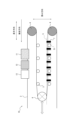
図9に例示するように、ルーパー設備1において、縦ロール7の長手方向における設置間隔Sを種々変更して、板厚2mm、長さ900mの鋼板2としての電磁鋼板製造用熱延板を搬送した。
用いた縦ロール7の材質は、クローム鋼(C:1.0%、Si:0.2%、Mn:0.3%、P:0.02%、S:0.02%、Cr:1.4%、残部はFeおよび不可避的不純物)とした。縦ロール7は円柱状であり、その大きさは、直径を110mm、高さを230mmとした。縦ロール7は、床面に固定された軸受け71により支持され、図7Aのようにさらにその長手方向両側および背面側(幅方向のうち鋼板と向かい合わない一方)を、架台5によって回転可能に支持した。本実施例では、縦ロール7にはガードを付けなかった。
(実施例1)
図9に例示するように、ルーパー設備1において、縦ロール7の長手方向における設置間隔Sを種々変更して、板厚2mm、長さ900mの鋼板2としての電磁鋼板製造用熱延板を搬送した。
用いた縦ロール7の材質は、クローム鋼(C:1.0%、Si:0.2%、Mn:0.3%、P:0.02%、S:0.02%、Cr:1.4%、残部はFeおよび不可避的不純物)とした。縦ロール7は円柱状であり、その大きさは、直径を110mm、高さを230mmとした。縦ロール7は、床面に固定された軸受け71により支持され、図7Aのようにさらにその長手方向両側および背面側(幅方向のうち鋼板と向かい合わない一方)を、架台5によって回転可能に支持した。本実施例では、縦ロール7にはガードを付けなかった。
図9には図示しないが、搬送方向最上流に位置する一対の縦ロール7は、固定ロールと最上流に位置する搬送ロールとの間に、該固定ロールよりも該搬送ロールに近い位置に設けた。具体的には、搬送方向最上流に位置する一対の縦ロール7の、固定ロールまでの距離を10mとし、最上流に位置する搬送ロールまでの距離を1mとした。
鋼板2と架台5とがなす距離Dを156mmとし、同様に鋼板2と架台脚51とがなす距離D1を156mmとし、縦ロール7の鋼板2に対する距離dを141mmに設定した。したがって、縦ロール7の搬送領域内側への入り込み長さ(D-d)および(D1-d)はともに15mmであった。また、搬送領域の幅は1.6mであり、鋼板の最大幅は1.3mであった。
図7Aも参照し、縦ロール7のルーパーカー6に対する下方への離間距離d2は100mmとした。また、縦ロール7の架台5に対する上方への離間距離d3は30mmとした。
図7Aも参照し、縦ロール7のルーパーカー6に対する下方への離間距離d2は100mmとした。また、縦ロール7の架台5に対する上方への離間距離d3は30mmとした。
なお、図9には示さないが、このルーパー設備1は、回転軸が鋼板2の幅方向に延びるように長手方向に3m間隔で設けられ、鋼板2の下面を支持する、複数の搬送ロールと;長手方向の一端部に設けられた3個の固定ロールと;長手方向の他端部に設けられ、架台5に沿って移動して鋼板2の貯留量を調整可能な2個のルーパーカーと;も有する。
鋼板2の幅方向に対をなす縦ロール7同士は、図9のように、該幅方向に対して長手方向にずれることなく向かい合って設置した。縦ロールは、全長150mの架台区間に対して設置した。
ここで、縦ロール7の長手方向における設置間隔Sを、それぞれ2.5m、5.0m、7.5m、10mと変更した。図9の例では、便宜上、図の左側から順に設置間隔S:2.5m、5.0m、7.5m、10mとした様子を一つのライン上に並べて示している。しかし実際には、設置間隔S:2.5m(計60対)、5.0m(計30対)、7.5m(計20対)および10m(計15対)のそれぞれを異なるライン上に並べ、これら設置間隔ごとに上記長さの鋼板2を一巻分搬送させた。また、比較として、縦ロールを設置する前、したがって縦ロールを有さない場合についても検討した。
なお、搬送速度などのその他の条件は、常法にしたがった。
ここで、縦ロール7の長手方向における設置間隔Sを、それぞれ2.5m、5.0m、7.5m、10mと変更した。図9の例では、便宜上、図の左側から順に設置間隔S:2.5m、5.0m、7.5m、10mとした様子を一つのライン上に並べて示している。しかし実際には、設置間隔S:2.5m(計60対)、5.0m(計30対)、7.5m(計20対)および10m(計15対)のそれぞれを異なるライン上に並べ、これら設置間隔ごとに上記長さの鋼板2を一巻分搬送させた。また、比較として、縦ロールを設置する前、したがって縦ロールを有さない場合についても検討した。
なお、搬送速度などのその他の条件は、常法にしたがった。
ルーパー設備内を搬送させてコイル状に巻き取った熱延板について、1個のコイル全長の側面を目視点検し、ガイド疵が一つでも確認されれば欠陥が発生したと判断した。そして、同様の実験を3000個のコイル分行うことにより、欠陥発生率(%)=ガイド疵が確認されたコイル数/通板させたコイル総数×100の式に従い、欠陥(ガイド疵)の発生率を求めた。
結果を、表1に示す。
結果を、表1に示す。

表1に示したとおり、ルーパー設備に所定の縦ロールを設けることによる、鋼板の欠陥発生率の低減効果が確認できた。また、縦ロールの設置間隔Sを調整することにより、設置前の欠陥発生率と比較して40%超、さらには50%超も欠陥発生率を低減することができた。
(実施例2)
縦ロール7の長手方向における設置間隔Sを2.5m間隔とした。また設置した60対全ての縦ロールに、図7A~Cに概略を示すガードをさらにつけた。上記以外は実験1と同様にして、熱延板の欠陥発生率を求めた。
ここで、ガードは、図7に例示する四角柱側面を構成する板状であり、鋼板厚み方向の高さが100mm、長手方向の長さが200mmの寸法で、縦ロール下面と軸受けとの隙間を覆う形状とした。ガードは、縦ロールの回転を妨げることのない程度の距離で該縦ロールから少なくとも10mm離間して、架台の壁面で支持して設置した。
縦ロール7の長手方向における設置間隔Sを2.5m間隔とした。また設置した60対全ての縦ロールに、図7A~Cに概略を示すガードをさらにつけた。上記以外は実験1と同様にして、熱延板の欠陥発生率を求めた。
ここで、ガードは、図7に例示する四角柱側面を構成する板状であり、鋼板厚み方向の高さが100mm、長手方向の長さが200mmの寸法で、縦ロール下面と軸受けとの隙間を覆う形状とした。ガードは、縦ロールの回転を妨げることのない程度の距離で該縦ロールから少なくとも10mm離間して、架台の壁面で支持して設置した。
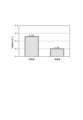
図10に、縦ロールの設置前と、縦ロールおよびガードを設置した後との、ルーパー設備を搬送させた熱延板に対する欠陥発生率を示す。設置前と比較して、設置後では、欠陥発生率がさらに減少していることが確認できた。具体的には、設置前の欠陥発生率と比較して60%超も欠陥発生率を低減することができた。
このように、縦ロールにさらに所定のガードをつけることにより、鋼板の欠陥発生率が一段と低減できることが確認できた。
このように、縦ロールにさらに所定のガードをつけることにより、鋼板の欠陥発生率が一段と低減できることが確認できた。
(実施例3)
実施例2でガードが鋼板の更なるガイド疵防止に効果的であったことを受け、実施例2と同様のガードを縦ロールに設けた、ガード付き縦ロールを用いた。また、実施例1と同様に設置間隔Sを2.5m、5.0m、7.5mおよび10m間隔となるようにそれぞれ設置した。そして、実施例1と同様の手法で熱延板への欠陥発生率を求めた。
結果を、表2に示す。
実施例2でガードが鋼板の更なるガイド疵防止に効果的であったことを受け、実施例2と同様のガードを縦ロールに設けた、ガード付き縦ロールを用いた。また、実施例1と同様に設置間隔Sを2.5m、5.0m、7.5mおよび10m間隔となるようにそれぞれ設置した。そして、実施例1と同様の手法で熱延板への欠陥発生率を求めた。
結果を、表2に示す。
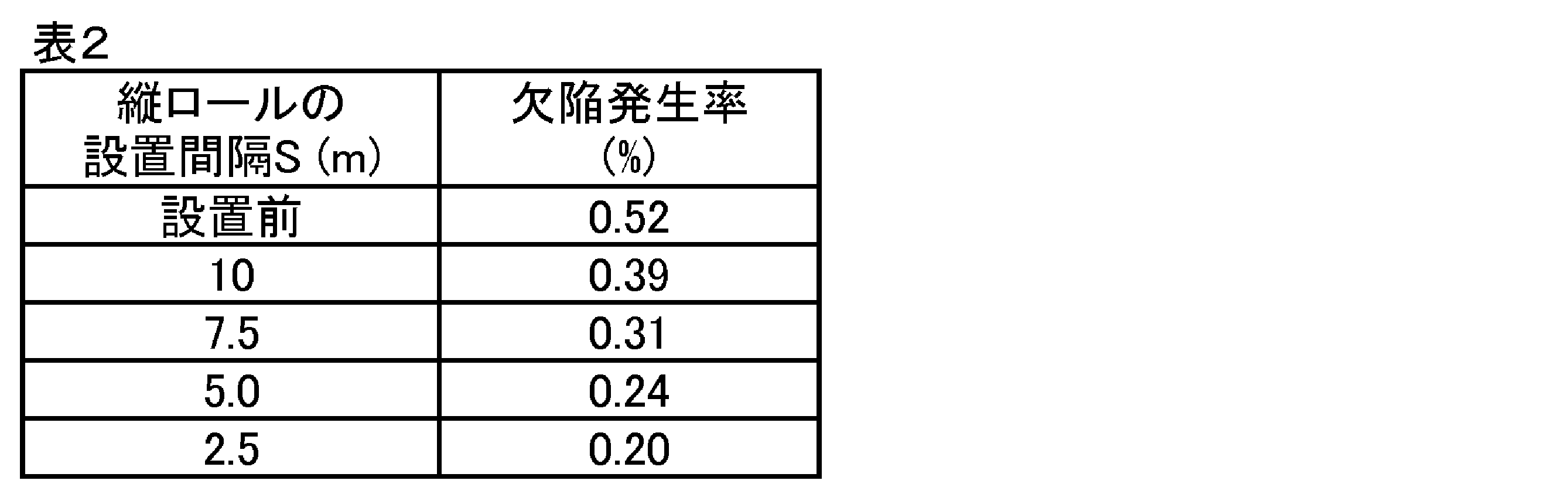
表2に示したとおり、縦ロールにさらに所定のガードをつけることにより、鋼板の欠陥発生率が一層低減できていることが確認できた。また、縦ロールの設置間隔Sを調整することにより、設置前の欠陥発生率と比較して40%超、さらには50%超、さらには60%超も欠陥発生率を低減することができた。
(実施例4)
縦ロールの長手方向における設置間隔Sを2.5m間隔(全60対)とした。また、縦ロールの大きさを、直径を110mm、高さを170mmとした。さらに、ルーパー設備を介して熱延板を酸洗装置に供給し、該熱延板に酸洗処理を行った。上記以外は実験1と同様にして、熱延板の欠陥発生率を求めた。
その結果、酸洗後の熱延板について、縦ロールの設置前における欠陥発生率0.52%から、その欠陥発生率が0.24%にまで抑えられた。このように、縦ロールにガードを付けることなく、異なる高さを有する縦ロールを設置した場合であっても、欠陥発生率の低減効果が確認できた。さらには、酸洗後の熱延板に対しても、欠陥発生率の低減効果が確認できた。
縦ロールの長手方向における設置間隔Sを2.5m間隔(全60対)とした。また、縦ロールの大きさを、直径を110mm、高さを170mmとした。さらに、ルーパー設備を介して熱延板を酸洗装置に供給し、該熱延板に酸洗処理を行った。上記以外は実験1と同様にして、熱延板の欠陥発生率を求めた。
その結果、酸洗後の熱延板について、縦ロールの設置前における欠陥発生率0.52%から、その欠陥発生率が0.24%にまで抑えられた。このように、縦ロールにガードを付けることなく、異なる高さを有する縦ロールを設置した場合であっても、欠陥発生率の低減効果が確認できた。さらには、酸洗後の熱延板に対しても、欠陥発生率の低減効果が確認できた。
1 ルーパー設備
10 熱延板酸洗設備
11 焼鈍炉(焼鈍装置)
12 冷却帯(冷却装置)
13 酸洗装置
2 鋼板(熱延板)
3 搬送ロール
4 固定ロール
5 架台
51 架台脚
6 ルーパーカー(ルーパーカーロール)
7 縦ロール
71 軸受け
72 ガード
D 鋼板と架台とがなす距離
D1 鋼板と架台脚とがなす距離
d 鋼板と縦ロールとがなす距離
d2 ルーパーカーと縦ロールとがなす距離
d3 支持部材(架台)と縦ロールとがなす距離
S 縦ロールの設置間隔
10 熱延板酸洗設備
11 焼鈍炉(焼鈍装置)
12 冷却帯(冷却装置)
13 酸洗装置
2 鋼板(熱延板)
3 搬送ロール
4 固定ロール
5 架台
51 架台脚
6 ルーパーカー(ルーパーカーロール)
7 縦ロール
71 軸受け
72 ガード
D 鋼板と架台とがなす距離
D1 鋼板と架台脚とがなす距離
d 鋼板と縦ロールとがなす距離
d2 ルーパーカーと縦ロールとがなす距離
d3 支持部材(架台)と縦ロールとがなす距離
S 縦ロールの設置間隔
Claims (6)
- 鋼板を貯留しながら長手方向に搬送可能なルーパー設備であって、
回転軸が前記鋼板の幅方向に延びるように前記長手方向に間隔をおいて設けられ、前記鋼板の片面を支持する、複数の搬送ロールと、
前記長手方向の一端部に設けられた少なくとも一つの固定ロールと、
前記鋼板の幅方向の両側に、前記長手方向に延びて設けられた架台と、
前記長手方向の他端部に設けられ、前記架台に沿って移動することにより前記鋼板の貯留量を調整可能な少なくとも一つのルーパーカーと、を有し、
前記鋼板の幅方向を挟む位置、かつ、前記鋼板に対する距離が、前記鋼板と前記架台とがなす距離よりも小さい位置に設けられ、回転軸が前記鋼板の厚み方向に延びるとともに前記鋼板の搬送方向に沿って回転可能な1対以上の縦ロールをさらに有することを特徴とする、ルーパー設備。 - 前記縦ロールが軸受けによって支持され、
前記縦ロールの底面と前記軸受けとの間にある隙間を覆うガードをさらに備える、請求項1に記載のルーパー設備。 - 前記縦ロールが2対以上設けられ、該縦ロールの前記長手方向における設置間隔が10m以下である、請求項1に記載のルーパー設備。
- 前記縦ロールが2対以上設けられ、該縦ロールの前記長手方向における設置間隔が10m以下である、請求項2に記載のルーパー設備。
- 前記鋼板が電磁鋼板用の熱延板であり、
請求項1~4のいずれか一項に記載のルーパー設備の前記搬送方向下流側に、前記熱延板を酸洗可能な酸洗装置をさらに備え、
前記熱延板が、前記ルーパー設備を介して前記酸洗装置に供給可能に構成される、熱延板酸洗設備。 - 前記鋼板が電磁鋼板製造用の熱延板であり、
前記熱延板を、請求項1~4のいずれか一項に記載のルーパー設備を介して、該ルーパー設備よりも前記搬送方向下流側に備えられた酸洗装置に供給することにより、前記熱延板に酸洗処理を施す、熱延板酸洗方法。
Priority Applications (1)
| Application Number | Priority Date | Filing Date | Title |
|---|---|---|---|
| JP2025504870A JP7662116B1 (ja) | 2023-11-07 | 2024-11-06 | ルーパー設備、熱延板酸洗設備および熱延板酸洗方法 |
Applications Claiming Priority (2)
| Application Number | Priority Date | Filing Date | Title |
|---|---|---|---|
| JP2023-190284 | 2023-11-07 | ||
| JP2023190284 | 2023-11-07 |
Publications (1)
| Publication Number | Publication Date |
|---|---|
| WO2025100461A1 true WO2025100461A1 (ja) | 2025-05-15 |
Family
ID=95695318
Family Applications (1)
| Application Number | Title | Priority Date | Filing Date |
|---|---|---|---|
| PCT/JP2024/039518 Pending WO2025100461A1 (ja) | 2023-11-07 | 2024-11-06 | ルーパー設備、熱延板酸洗設備および熱延板酸洗方法 |
Country Status (1)
| Country | Link |
|---|---|
| WO (1) | WO2025100461A1 (ja) |
Citations (3)
| Publication number | Priority date | Publication date | Assignee | Title |
|---|---|---|---|---|
| JPS5841602A (ja) * | 1981-09-03 | 1983-03-10 | Sumitomo Metal Ind Ltd | 冷間圧延方法 |
| JPH07116725A (ja) * | 1993-10-22 | 1995-05-09 | Nkk Corp | ルーパーにおけるストリップの蛇行制御方法 |
| JP2005334949A (ja) * | 2004-05-28 | 2005-12-08 | Jfe Steel Kk | 鋼板の蛇行防止方法およびルーパ設備 |
-
2024
- 2024-11-06 WO PCT/JP2024/039518 patent/WO2025100461A1/ja active Pending
Patent Citations (3)
| Publication number | Priority date | Publication date | Assignee | Title |
|---|---|---|---|---|
| JPS5841602A (ja) * | 1981-09-03 | 1983-03-10 | Sumitomo Metal Ind Ltd | 冷間圧延方法 |
| JPH07116725A (ja) * | 1993-10-22 | 1995-05-09 | Nkk Corp | ルーパーにおけるストリップの蛇行制御方法 |
| JP2005334949A (ja) * | 2004-05-28 | 2005-12-08 | Jfe Steel Kk | 鋼板の蛇行防止方法およびルーパ設備 |
Similar Documents
| Publication | Publication Date | Title |
|---|---|---|
| US4074555A (en) | Method of and apparatus for improving hot-rolled sheet-metal strips | |
| JP7192378B2 (ja) | 圧延設備及び鋼板の圧延方法 | |
| WO2004000476A1 (en) | Hot rolling method and apparatus for hot steel sheet | |
| JP2023530544A (ja) | 熱間圧延極薄鋼帯の連続生産のためのプラントおよび方法 | |
| JP4091910B2 (ja) | レールの製造方法および製造設備 | |
| US5412966A (en) | Push-pull pickle line | |
| JP7662116B1 (ja) | ルーパー設備、熱延板酸洗設備および熱延板酸洗方法 | |
| JP5353260B2 (ja) | 高強度厚肉熱延鋼板の巻き取り設備および巻き取り方法 | |
| JP6922873B2 (ja) | 調質圧延方法、調質圧延装置および鋼板の製造方法 | |
| KR101311115B1 (ko) | 스트립 이송용 루프 구조체 | |
| JP3927536B2 (ja) | 連続熱間圧延ラインにおける搬送制御方法 | |
| TWI799028B (zh) | 冷軋鋼板的製造方法及製造設備 | |
| JP6922668B2 (ja) | 熱間圧延方法、及び熱間圧延機列 | |
| JP6337853B2 (ja) | 鋼板の調質圧延方法 | |
| JPH0318416A (ja) | 熱間仕上圧延機出側のラン・アウト・テーブル | |
| JP5487803B2 (ja) | 金属帯の蛇行防止方法ならびに金属帯連続処理設備 | |
| TWI797912B (zh) | 冷軋鋼板的製造方法及製造設備 | |
| JPH1080701A (ja) | 走間溶接設備の加熱型クランプ装置およびこのクランプ装置を用いたクランプ方法 | |
| EP0040653B1 (en) | Method for preventing wandering of strip under roller leveling in hot rolling line | |
| JP4352700B2 (ja) | 鋼帯の形状矯正方法 | |
| JP3788323B2 (ja) | 熱間圧延ライン及び熱間圧延方法 | |
| KR101443083B1 (ko) | 소재 권취장치 | |
| JPH0688063B2 (ja) | 帯鋼のスキンパスミル | |
| JP3353713B2 (ja) | 熱延鋼帯を有するホットランテーブル及び熱延鋼帯の製造方法 | |
| KR20250091966A (ko) | 강판의 코일링 안내장치 및 이를 이용한 강판의 코일링 안내방법 |
Legal Events
| Date | Code | Title | Description |
|---|---|---|---|
| ENP | Entry into the national phase |
Ref document number: 2025504870 Country of ref document: JP Kind code of ref document: A |
|
| WWE | Wipo information: entry into national phase |
Ref document number: 2025504870 Country of ref document: JP |
|
| 121 | Ep: the epo has been informed by wipo that ep was designated in this application |
Ref document number: 24888754 Country of ref document: EP Kind code of ref document: A1 |