WO2025100225A1 - 流体圧シリンダユニット - Google Patents
流体圧シリンダユニット Download PDFInfo
- Publication number
- WO2025100225A1 WO2025100225A1 PCT/JP2024/037589 JP2024037589W WO2025100225A1 WO 2025100225 A1 WO2025100225 A1 WO 2025100225A1 JP 2024037589 W JP2024037589 W JP 2024037589W WO 2025100225 A1 WO2025100225 A1 WO 2025100225A1
- Authority
- WO
- WIPO (PCT)
- Prior art keywords
- cylinder
- pressure chamber
- chamber
- pressure
- piston
- Prior art date
- Legal status (The legal status is an assumption and is not a legal conclusion. Google has not performed a legal analysis and makes no representation as to the accuracy of the status listed.)
- Pending
Links
Images


Classifications
-
- B—PERFORMING OPERATIONS; TRANSPORTING
- B66—HOISTING; LIFTING; HAULING
- B66F—HOISTING, LIFTING, HAULING OR PUSHING, NOT OTHERWISE PROVIDED FOR, e.g. DEVICES WHICH APPLY A LIFTING OR PUSHING FORCE DIRECTLY TO THE SURFACE OF A LOAD
- B66F9/00—Devices for lifting or lowering bulky or heavy goods for loading or unloading purposes
- B66F9/06—Devices for lifting or lowering bulky or heavy goods for loading or unloading purposes movable, with their loads, on wheels or the like, e.g. fork-lift trucks
- B66F9/075—Constructional features or details
- B66F9/20—Means for actuating or controlling masts, platforms, or forks
- B66F9/22—Hydraulic devices or systems
-
- F—MECHANICAL ENGINEERING; LIGHTING; HEATING; WEAPONS; BLASTING
- F15—FLUID-PRESSURE ACTUATORS; HYDRAULICS OR PNEUMATICS IN GENERAL
- F15B—SYSTEMS ACTING BY MEANS OF FLUIDS IN GENERAL; FLUID-PRESSURE ACTUATORS, e.g. SERVOMOTORS; DETAILS OF FLUID-PRESSURE SYSTEMS, NOT OTHERWISE PROVIDED FOR
- F15B15/00—Fluid-actuated devices for displacing a member from one position to another; Gearing associated therewith
- F15B15/08—Characterised by the construction of the motor unit
- F15B15/14—Characterised by the construction of the motor unit of the straight-cylinder type
-
- F—MECHANICAL ENGINEERING; LIGHTING; HEATING; WEAPONS; BLASTING
- F15—FLUID-PRESSURE ACTUATORS; HYDRAULICS OR PNEUMATICS IN GENERAL
- F15B—SYSTEMS ACTING BY MEANS OF FLUIDS IN GENERAL; FLUID-PRESSURE ACTUATORS, e.g. SERVOMOTORS; DETAILS OF FLUID-PRESSURE SYSTEMS, NOT OTHERWISE PROVIDED FOR
- F15B15/00—Fluid-actuated devices for displacing a member from one position to another; Gearing associated therewith
- F15B15/18—Combined units comprising both motor and pump
-
- F—MECHANICAL ENGINEERING; LIGHTING; HEATING; WEAPONS; BLASTING
- F15—FLUID-PRESSURE ACTUATORS; HYDRAULICS OR PNEUMATICS IN GENERAL
- F15B—SYSTEMS ACTING BY MEANS OF FLUIDS IN GENERAL; FLUID-PRESSURE ACTUATORS, e.g. SERVOMOTORS; DETAILS OF FLUID-PRESSURE SYSTEMS, NOT OTHERWISE PROVIDED FOR
- F15B15/00—Fluid-actuated devices for displacing a member from one position to another; Gearing associated therewith
- F15B15/20—Other details, e.g. assembly with regulating devices
- F15B15/22—Other details, e.g. assembly with regulating devices for accelerating or decelerating the stroke
Definitions
- the present invention relates to a fluid pressure cylinder unit.
- JP2021-172516A discloses a vehicle (forklift) equipped with a vehicle body, a loading section supported by the vehicle body and capable of loading cargo, a lift cylinder for raising and lowering the loading section, and an accumulator that can communicate with the lift cylinder.
- the accumulator suppresses fluctuations in pressure in the chamber by introducing fluid to accumulate pressure when pressure in the lift cylinder increases and releasing the accumulated fluid when pressure in the chamber decreases. In this way, sudden pressure changes in the chamber are suppressed, thereby suppressing vertical vibration of cargo loaded on the loading section.
- the present invention aims to make it easier to handle fluid pressure cylinder units.
- a fluid pressure cylinder unit comprising: a fluid pressure cylinder having a cylinder tube, a piston rod reciprocatably disposed within the cylinder tube and dividing the interior of the cylinder tube into a rod chamber and a bottom chamber, for driving a driven object; a supply and exhaust passage connected to the bottom chamber and supplying a working fluid to the bottom chamber or discharging a working fluid from the bottom chamber; and a shock absorber connected to the supply and exhaust passage, the shock absorber having a cylinder, a piston reciprocably disposed within the cylinder and dividing the interior of the cylinder into a first pressure chamber and a second pressure chamber, a communication passage connecting the first pressure chamber and the second pressure chamber, and a biasing member biasing the piston in a direction in which the first pressure chamber contracts, and the bottom chamber is connected to the first pressure chamber or the second pressure chamber through the supply and exhaust passage.
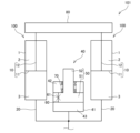
- FIG. 1 is a circuit diagram of a fluid pressure cylinder unit according to an embodiment of the present invention.
- FIG. 2 is a front view of the fluid pressure cylinder unit according to the embodiment of the present invention.
- FIG. 3 is a schematic diagram showing how a shock is absorbed by a shock absorber.
- FIG. 4 is a circuit diagram of a fluid pressure cylinder unit according to a first modified example of the embodiment of the present invention.
- FIG. 5 is a circuit diagram of a fluid pressure cylinder unit according to a second modified example of the embodiment of the present invention.
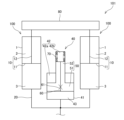
- FIG. 6 is a circuit diagram of a fluid pressure cylinder unit according to a third modified example of the embodiment of the present invention.
- FIG. 7 is a circuit diagram of a fluid pressure cylinder unit according to a fourth modified example of the embodiment of the present invention.
- the fluid pressure cylinder unit 101 includes a fluid pressure cylinder.
- the fluid pressure cylinder is a lift cylinder 100 that drives (raises and lowers) the forks 80 that are the driving objects of the forklift, and a case will be described in which a pair of lift cylinders 100 are provided.
- the lift cylinder 100 is a single-acting hydraulic cylinder. As shown in FIG. 1, the lift cylinder 100 has a cylinder tube 1 and a piston rod 10 that is reciprocally movable within the cylinder tube 1 and divides the cylinder tube 1 into a rod chamber 2 and a bottom chamber 3.
- the piston rod 10 has a piston 11 that is slidably mounted along the inner circumferential surface of the cylinder tube 1, and a rod 12 that has one end connected to the piston 11 and the other end extending outward from the cylinder tube 1 and reciprocates.
- the rod chamber 2 is filled with a gas such as air. Gas enters and leaves the rod chamber 2, or is compressed or expanded, according to the movement of the piston rod 10. Hydraulic oil is supplied to and discharged from the bottom chamber 3 as a working fluid through a supply and discharge passage 20, which will be described later. Note that fluids other than hydraulic oil, such as water or a water-soluble substitute liquid, may also be used as the working fluid.
- the fluid pressure cylinder unit 101 includes a supply/discharge passage 20 connected to the bottom chamber 3, and a shock absorber 40 connected to the supply/discharge passage 20.
- a shock absorber 40 is intended to absorb the impact applied to the forks 80 from the road surface.
- the supply and discharge passage 20 is connected to both bottom chambers 3 of the pair of lift cylinders 100.
- the supply and discharge passage 20 has a hydraulic hose 21 (see FIG. 2) and a joint 22 (see FIG. 2), and is connected to a pump (not shown) or a tank (not shown) by a switching valve (not shown).
- the supply and discharge passage 20 supplies hydraulic oil to the bottom chamber 3 or discharges hydraulic oil from the bottom chamber 3.
- the piston rod 10 reciprocates as hydraulic oil is supplied to and discharged from the bottom chamber 3 through the supply and discharge passage 20. Specifically, when hydraulic oil is supplied from the pump to the bottom chamber 3, the piston rod 10 moves upward (upward in FIG.
- the shock absorber 40 is provided between a pair of lift cylinders 100 (see FIG. 2).
- the shock absorber 40 has a cylinder 41, a piston rod 50 that is provided reciprocally within the cylinder 41 and divides the cylinder 41 into a first pressure chamber 43 and a second pressure chamber 42, a communication passage 60 that connects the first pressure chamber 43 and the second pressure chamber 42, and a spring 70 as a biasing member that biases the piston rod 50 in the direction in which the first pressure chamber 43 contracts.
- the shock absorber 40 is formed separately from the lift cylinder 100, and as shown in FIG. 2, the shock absorber 40 and the lift cylinder 100 are connected to the supply and exhaust passage 20 and provided adjacent to each other side by side.
- the piston rod 50 has a piston 51 that is reciprocally movable within the cylinder 41 and divides the cylinder 41 into a first pressure chamber 43 and a second pressure chamber 42, and a rod 52 that is reciprocally movable within the cylinder 41 and has the piston 51 connected to its tip.
- the rod 52 is provided in the second pressure chamber 42 and extends outside the cylinder 41, and the second pressure chamber 42 is located above the first pressure chamber 43.
- the second pressure chamber 42 is provided on the rod 52 side.
- the supply and discharge passage 20 communicates with the first pressure chamber 43.
- the bottom chamber 3 of the lift cylinder 100 communicates with the first pressure chamber 43 through the supply and discharge passage 20.
- the communication passage 60 is provided axially through the piston 51 and communicates between the first pressure chamber 43 and the second pressure chamber 42.
- the communication passage 60 has an orifice 61 as a throttling section that provides resistance to the flow of hydraulic oil. Therefore, the orifice 61 applies resistance to the hydraulic oil moving between the first pressure chamber 43 and the second pressure chamber 42 through the communication passage 60.
- the spring 70 is provided in the second pressure chamber 42 so as to surround the rod 52 in the second pressure chamber 42.
- FIG. 3 is a schematic diagram showing the operation of the shock absorber 40 to absorb the shock applied to the fork 80.
- Figure 3(a) shows the state in which the lift cylinder 100 is lifting the forks 80 while traveling and before an impact is applied to the forks 80.
- pressure acts on the bottom chamber 3 of the lift cylinder 100 via the piston rod 10 due to the weight of the forks 80 and the luggage.
- the bottom chamber 3 is connected to the first pressure chamber 43 of the shock absorber 40 through the supply and discharge passage 20, the piston 51 of the shock absorber 40 moves upward and floats above the bottom surface of the cylinder 41.
- the load due to the pressure in the first pressure chamber 43 is balanced by the combined force of the load due to the pressure in the second pressure chamber 42 and the biasing force of the spring 70.
- the spring 70 has a compression margin.
- the shock absorber 40 when the pressure in the first pressure chamber 43 rises and the load due to the pressure in the first pressure chamber 43 exceeds the combined force of the load due to the pressure in the second pressure chamber 42 and the biasing force of the spring 70, the hydraulic oil in the second pressure chamber 42 moves to the first pressure chamber 43 through the communication passage 60 and the orifice 61, as shown by arrow A in FIG. 3(c), and the piston rod 50 moves upward and the shock absorber 40 extends.
- the first pressure chamber 43 expands and the pressure decreases, so that hydraulic oil is guided from the bottom chamber 3 of the lift cylinder 100 to the first pressure chamber 43 through the supply and discharge passage 20, and the piston rod 10 moves downward as shown by arrow B in FIG.
- the amount of movement of the piston rod 10 corresponds to the amount of movement of the piston rod 50. Specifically, the bottom chamber 3 shrinks by the amount of the piston rod 50 withdrawn from the cylinder 41, and the piston rod 10 moves. In other words, the greater the amount of movement of the piston rod 50, the greater the amount of movement of the piston rod 10, and the easier it is to absorb the impact on the fork 80.
- the hydraulic oil in the second pressure chamber 42 moves through the orifice 61 to the first pressure chamber 43, and the orifice 61 exerts a damping force, so the impact on the fork 80 is absorbed while being damped.
- the fluid pressure cylinder unit 101 it is also possible to use an accumulator filled with high-pressure gas instead of the shock absorber 40 to absorb the impact applied to the fork 80.
- high-pressure gas is subject to legal restrictions, it is not easy to transport an accumulator filled with high-pressure gas, and it is also not easy to transport and use a gas cylinder containing the high-pressure gas to be sealed in the accumulator, and there is also the problem that government approval is required. Therefore, such a fluid pressure cylinder unit 101 is difficult to handle.
- the shock absorber 40 absorbs the impact on the fork 80, rather than an accumulator filled with high-pressure gas. This makes the fluid pressure cylinder unit 101 easier to handle.
- the communication passage 60 has an orifice 61 that provides resistance to the flow of hydraulic oil, and the orifice 61 exerts a damping force.
- the orifice 61 provides resistance to the hydraulic oil moving from the second pressure chamber 42 to the first pressure chamber 43 through the communication passage 60, thereby damping the impact.
- the orifice 61 can absorb the impact on the fork 80 while damping it, so that the impact on the fork 80 is absorbed more effectively.
- the shock absorber 40 absorbs the impact on the fork 80
- the shock absorber 40 repeatedly expands and contracts, causing the piston rod 50 to repeatedly reciprocate, and the piston rod 10 of the lift cylinder 100 also repeatedly reciprocates, which may cause the fork 80 to vibrate.
- the reciprocating motion of the piston rod 50 is damped by the orifice 61, so the vibration of the fork 80 is suppressed.
- the pressure receiving area of the piston 51 facing the first pressure chamber 43 and the second pressure chamber 42 is different. Specifically, the pressure receiving area of the piston 51 facing the first pressure chamber 43 is larger than the pressure receiving area facing the second pressure chamber 42 by the cross-sectional area of the rod 52. This makes it easier for the piston 51 to move due to pressure changes in the first pressure chamber 43 and the second pressure chamber 42, and the amount of movement of the piston 51 increases. Therefore, the amount of movement of the piston rod 10 of the lift cylinder 100 increases, and the impact applied to the fork 80 is absorbed more effectively.
- shock absorber 40 is connected to the supply and exhaust passage 20, it can be attached to an existing lift cylinder 100 as an attachment. This allows it to be easily replaced with an accumulator, making it easy to handle.
- the shock absorber 40 is also arranged alongside the lift cylinder 100 in the supply and discharge passage 20. This allows the fluid pressure cylinder unit 101 to be made compact.
- the strength (spring constant) of the spring 70 is set, for example, so that when an impact is applied to the fork 80, the bottom chamber 3 of the lift cylinder 100 contracts to ensure the amount of movement of the piston 51 that can absorb the impact.
- the bottom chamber 3 becomes high pressure
- the first pressure chamber 43 that communicates with the bottom chamber 3 becomes high pressure.
- This causes hydraulic oil to move between the first pressure chamber 43 and the second pressure chamber 42 through the communication passage 60, and the piston 51 of the shock absorber 40 moves, causing the bottom chamber 3 to shrink.
- This absorbs the impact applied to the fork 80.
- the impact applied to the fork 80 is absorbed by the shock absorber 40 rather than by an accumulator in which high-pressure gas is sealed, making it easier to handle.
- the bottom chamber 3 of the lift cylinder 100 communicates with the first pressure chamber 43 through the supply and discharge passage 20.
- the bottom chamber 3 may communicate with the second pressure chamber 42 through the supply and discharge passage 20.
- the rod 52 is provided to extend in the direction in which the piston 51 moves first when an impact is applied to the fork 80 (upward in Figs. 1 and 4).
- the rod 52 is provided so that the pressure-receiving area of the piston 51 in the direction in which the piston 51 moves first when an impact is applied to the fork 80 (towards the second pressure chamber 42) is reduced, making it easier for the piston 51 to move.
- the inside of the cylinder 41 of the shock absorber 40 is divided into a first pressure chamber 43 and a second pressure chamber 42 by the piston 51.
- the second pressure chamber 42 may be divided into a third pressure chamber 42a and a fourth pressure chamber 42b by the rod 52.
- the third pressure chamber 42a is divided by the piston 51, the outer circumferential surface of the rod 52, and the cylinder 41, and communicates with a tank (not shown in the figure) or the atmosphere through a passage (not shown in the figure).
- the fourth pressure chamber 42b is divided by the end surface of the rod 52 and the cylinder 41.
- the communication passage 60 communicates the first pressure chamber 43 and the fourth pressure chamber 42b, and the spring 70 is provided in the fourth pressure chamber 42b and biases the piston 51 in a direction in which the first pressure chamber 43 contracts.
- the piston 51 is formed in a disk shape.
- the piston 51 may be formed in a concave shape as shown in Fig. 6.
- the rod 52 has a base end (upper end in Fig. 6) fixed to an instrument or the like, and a tip end (lower end in Fig. 6) provided in the concave portion of the piston 51.
- the second pressure chamber 42 is defined by the concave portion of the piston 51 and the tip end of the rod 52.
- the shock absorber 40 is provided separately from the lift cylinder 100.
- the shock absorber 40 is provided in the piston rod 310 of the lift cylinder 400.
- the cylinder 41 of the shock absorber 40 is provided as a space in the piston rod 310, and the piston rod 50 and the spring 70 are provided in the cylinder 41.
- the supply and discharge passage 20 has a first supply and discharge passage 20a connected to the bottom chamber 3 of the lift cylinder 100, and a second supply and discharge passage 20b connecting the bottom chamber 3 with the first pressure chamber 43 of the shock absorber 40.
- the supply and discharge passage 20 supplies hydraulic oil to the bottom chamber 3 or discharges hydraulic oil from the bottom chamber 3.
- the shock absorber 40 may also be provided in the cylinder tube 1 of the lift cylinder 100. Specifically, the shock absorber 40 may be provided on the bottom chamber 3 side in the cylinder tube 1 of the lift cylinder 100. The shock absorber 40 is provided upside down from the orientation shown in Figs. 1 and 7, so that the first pressure chamber 43 communicates with the bottom chamber 3.
- the supply and discharge passage 20 has a first supply and discharge passage 20a connected to the bottom chamber 3 of the lift cylinder 100 and a second supply and discharge passage 20b communicating the bottom chamber 3 with the first pressure chamber 43, and the supply and discharge passage 20 supplies hydraulic oil to the bottom chamber 3 or discharges hydraulic oil from the bottom chamber 3. Even with this configuration, the fluid pressure cylinder unit 401 can be made compact.
- the communication passage 60 has the orifice 61 that provides resistance to the flow of hydraulic oil, and a damping force is exerted by the orifice 61.
- the orifice 61 is not an essential component, and the communication passage 60 does not need to have the orifice 61 as long as the shock absorber 40 can absorb the impact.
- a relief valve may be provided instead of the orifice 61.
- the communication passage 60 is provided in the piston 51, and the spring 70 is provided in the second pressure chamber 42.
- the present invention is not limited to this, and the communication passage 60 may be provided in the cylinder 41 or outside the cylinder 41 as long as it communicates between the first pressure chamber 43 and the second pressure chamber 42.
- the spring 70 may be provided in a location other than the second pressure chamber 42 or outside the cylinder 41 as long as it biases the piston 51 in a direction in which the first pressure chamber 43 contracts.
- the spring 70 may be provided in the first pressure chamber 43 in a state extended longer than its natural length.
- the piston 51 is provided with the communication passage 60 having the orifice 61.
- the piston 51 may be provided with a passage having a check valve that allows only the flow of hydraulic oil from the first pressure chamber 43 to the second pressure chamber 42.
- the fluid pressure cylinder is the lift cylinder 100 that raises and lowers the forks 80 of a forklift.
- the fluid pressure cylinder is not limited to this, and may be a cylinder mounted on an industrial machine other than a forklift.
- the fluid pressure cylinder may be a double rod type cylinder.
- one or more than two fluid pressure cylinders may be provided in the fluid pressure cylinder unit 101.
- the fluid pressure cylinder unit 101, 401 comprises a cylinder tube 1, a piston rod 10, 310 which is reciprocatably provided within the cylinder tube 1 and divides the interior of the cylinder tube 1 into a rod chamber 2 and a bottom chamber 3, a lift cylinder 100, 400 which serves as a fluid pressure cylinder for driving a fork 80 which serves as a driven object, a supply and exhaust passage 20 which is connected to the bottom chamber 3 and supplies working fluid to the bottom chamber 3 or exhausts working fluid from the bottom chamber 3, and a shock absorber 40 which is connected to the supply and exhaust passage 20, the shock absorber 40 having a cylinder 41, a piston 51 which is reciprocatably provided within the cylinder 41 and divides the interior of the cylinder 41 into a first pressure chamber 43 and a second pressure chamber 42, a communication passage 60 which communicates between the first pressure chamber 43 and the second pressure chamber 42, and a spring 70 which serves as a biasing member which biases the piston 51 in a direction which causes the first pressure chamber 43 to contract, and the bottom chamber 3
- the communication passage 60 has an orifice 61 that acts as a throttle section that provides resistance to the flow of the working fluid.
- the orifice 61 exerts a damping force, so that the shock applied to the fork 80 is absorbed more effectively.
- the shock absorber 40 has a rod 52 that is connected to a piston 51 at its tip and is arranged so as to be able to reciprocate within the cylinder 41, and the rod 52 is arranged in the second pressure chamber 42.
- the rod 52 causes the pressure-receiving area of the piston 51 facing the first pressure chamber 43 and the second pressure chamber 42 to differ. This makes it easier for the piston 51 to move due to pressure changes in the first pressure chamber 43 and the second pressure chamber 42, and shocks applied to the fork 80 are absorbed more effectively.
- the shock absorber 40 is provided inside the lift cylinder 400.
- This configuration allows the fluid pressure cylinder unit 401 to be made compact.
Landscapes
- Engineering & Computer Science (AREA)
- Mechanical Engineering (AREA)
- Physics & Mathematics (AREA)
- Fluid Mechanics (AREA)
- General Engineering & Computer Science (AREA)
- Structural Engineering (AREA)
- Transportation (AREA)
- Combustion & Propulsion (AREA)
- Civil Engineering (AREA)
- Chemical & Material Sciences (AREA)
- Life Sciences & Earth Sciences (AREA)
- Geology (AREA)
- Forklifts And Lifting Vehicles (AREA)
- Actuator (AREA)
Applications Claiming Priority (2)
| Application Number | Priority Date | Filing Date | Title |
|---|---|---|---|
| JP2023189152A JP7801292B2 (ja) | 2023-11-06 | 2023-11-06 | 流体圧シリンダユニット |
| JP2023-189152 | 2023-11-06 |
Publications (1)
| Publication Number | Publication Date |
|---|---|
| WO2025100225A1 true WO2025100225A1 (ja) | 2025-05-15 |
Family
ID=95695433
Family Applications (1)
| Application Number | Title | Priority Date | Filing Date |
|---|---|---|---|
| PCT/JP2024/037589 Pending WO2025100225A1 (ja) | 2023-11-06 | 2024-10-22 | 流体圧シリンダユニット |
Country Status (2)
| Country | Link |
|---|---|
| JP (1) | JP7801292B2 (https=) |
| WO (1) | WO2025100225A1 (https=) |
Citations (4)
| Publication number | Priority date | Publication date | Assignee | Title |
|---|---|---|---|---|
| JPH0312897U (https=) * | 1989-06-23 | 1991-02-08 | ||
| DE4019075A1 (de) * | 1989-11-10 | 1991-12-19 | Jungheinrich Ag | Stapelfahrzeug mit einem beweglich an ihm angeordneten hubgeruest |
| JP2002160894A (ja) * | 2000-09-21 | 2002-06-04 | Anders Fransson | 低吊り上げフォークリフト |
| JP2006292057A (ja) * | 2005-04-11 | 2006-10-26 | Kayaba Ind Co Ltd | フロントフォーク |
Family Cites Families (5)
| Publication number | Priority date | Publication date | Assignee | Title |
|---|---|---|---|---|
| JPS61282610A (ja) * | 1985-06-07 | 1986-12-12 | Smc Corp | 速度制御機構を有するシリンダ装置 |
| DE3710776A1 (de) * | 1987-03-31 | 1988-10-20 | Jungheinrich Kg | Gabelhubwagen mit einem lenkbaren antriebsteil und einem an diesem gefuehrten hoehenbeweglichen lastteil |
| DE3937404A1 (de) * | 1989-11-10 | 1991-05-16 | Jungheinrich Kg | Stapelfahrzeug mit einem beweglich an ihm angeordneten hubgeruest |
| JP3843303B2 (ja) * | 1998-04-13 | 2006-11-08 | カヤバ工業株式会社 | サスペンション装置 |
| JPH11336824A (ja) * | 1998-05-28 | 1999-12-07 | Nissan Motor Co Ltd | 多段式流体圧シリンダ |
-
2023
- 2023-11-06 JP JP2023189152A patent/JP7801292B2/ja active Active
-
2024
- 2024-10-22 WO PCT/JP2024/037589 patent/WO2025100225A1/ja active Pending
Patent Citations (4)
| Publication number | Priority date | Publication date | Assignee | Title |
|---|---|---|---|---|
| JPH0312897U (https=) * | 1989-06-23 | 1991-02-08 | ||
| DE4019075A1 (de) * | 1989-11-10 | 1991-12-19 | Jungheinrich Ag | Stapelfahrzeug mit einem beweglich an ihm angeordneten hubgeruest |
| JP2002160894A (ja) * | 2000-09-21 | 2002-06-04 | Anders Fransson | 低吊り上げフォークリフト |
| JP2006292057A (ja) * | 2005-04-11 | 2006-10-26 | Kayaba Ind Co Ltd | フロントフォーク |
Also Published As
| Publication number | Publication date |
|---|---|
| JP2025077162A (ja) | 2025-05-19 |
| JP7801292B2 (ja) | 2026-01-16 |
Similar Documents
| Publication | Publication Date | Title |
|---|---|---|
| US8561767B2 (en) | Shock absorber having self pumping unit | |
| JP5936271B2 (ja) | 懸架装置 | |
| CA2535174C (en) | Shock absorber assembly | |
| EP1937995B1 (en) | Arrangement for telescopic fork leg with parallel damping | |
| JP6595831B2 (ja) | サスペンション装置およびアキュムレータ | |
| CN112243413B (zh) | 用于带水平调节的车辆底盘的减振器单元 | |
| CN105443636A (zh) | 混合连通式油气减震装置 | |
| JP6128636B2 (ja) | 緩衝器 | |
| JP6692686B2 (ja) | フォークリフト | |
| CN101857039B (zh) | 铁道车辆用线性减震器 | |
| WO2025100225A1 (ja) | 流体圧シリンダユニット | |
| RU2426921C2 (ru) | Амортизатор | |
| JP3088552B2 (ja) | 車高調整装置 | |
| KR20050040739A (ko) | 유압 실린더 | |
| CN205064675U (zh) | 单活塞杆双缸筒油气弹簧缸 | |
| JP4415410B2 (ja) | サスペンション | |
| CN205064674U (zh) | 双活塞杆油气弹簧缸 | |
| KR102486887B1 (ko) | 유압 액추에이터 및 이를 포함하는 차량용 액티브 서스펜션 장치 | |
| CN210290574U (zh) | 一种双缸筒双气室油气弹簧 | |
| WO2010125856A1 (ja) | 複筒型液圧緩衝器 | |
| JP2024067462A (ja) | 流体圧シリンダユニット | |
| CN222894552U (zh) | 一种自适应变刚度的油气弹簧总成结构及其车身安装结构 | |
| RU2089406C1 (ru) | Пневмогидравлическая рессора | |
| CN206802173U (zh) | 一种用于汽车的液压式减震器 | |
| JP2000074120A (ja) | 二段伸縮式油圧緩衝器 |
Legal Events
| Date | Code | Title | Description |
|---|---|---|---|
| 121 | Ep: the epo has been informed by wipo that ep was designated in this application |
Ref document number: 24888523 Country of ref document: EP Kind code of ref document: A1 |
|
| DPE1 | Request for preliminary examination filed after expiration of 19th month from priority date (pct application filed from 20040101) |