WO2025095083A1 - 高湿度保管庫 - Google Patents
高湿度保管庫 Download PDFInfo
- Publication number
- WO2025095083A1 WO2025095083A1 PCT/JP2024/038959 JP2024038959W WO2025095083A1 WO 2025095083 A1 WO2025095083 A1 WO 2025095083A1 JP 2024038959 W JP2024038959 W JP 2024038959W WO 2025095083 A1 WO2025095083 A1 WO 2025095083A1
- Authority
- WO
- WIPO (PCT)
- Prior art keywords
- space
- air
- temperature
- humidity
- cooling device
- Prior art date
- Legal status (The legal status is an assumption and is not a legal conclusion. Google has not performed a legal analysis and makes no representation as to the accuracy of the status listed.)
- Pending
Links
Images






Classifications
-
- F—MECHANICAL ENGINEERING; LIGHTING; HEATING; WEAPONS; BLASTING
- F25—REFRIGERATION OR COOLING; COMBINED HEATING AND REFRIGERATION SYSTEMS; HEAT PUMP SYSTEMS; MANUFACTURE OR STORAGE OF ICE; LIQUEFACTION SOLIDIFICATION OF GASES
- F25D—REFRIGERATORS; COLD ROOMS; ICE-BOXES; COOLING OR FREEZING APPARATUS NOT OTHERWISE PROVIDED FOR
- F25D11/00—Self-contained movable devices, e.g. domestic refrigerators
-
- F—MECHANICAL ENGINEERING; LIGHTING; HEATING; WEAPONS; BLASTING
- F25—REFRIGERATION OR COOLING; COMBINED HEATING AND REFRIGERATION SYSTEMS; HEAT PUMP SYSTEMS; MANUFACTURE OR STORAGE OF ICE; LIQUEFACTION SOLIDIFICATION OF GASES
- F25D—REFRIGERATORS; COLD ROOMS; ICE-BOXES; COOLING OR FREEZING APPARATUS NOT OTHERWISE PROVIDED FOR
- F25D23/00—General constructional features
Definitions
- This embodiment relates to a storage facility, a refrigerated goods transport vehicle equipped with the storage facility, and a logistics system.
- Patent Document 1 discloses a refrigerator that can promote aging of foods such as meat or fish while suppressing the growth of putrefactive bacteria and preventing excessive drying.
- the refrigerator includes a storage chamber for storing foods such as meat or fish, an airflow supply unit that is provided with a cooler, a heater, and an evaporator and circulates gas at a temperature of -2°C or higher and 5°C or lower and an average relative humidity of 60% to 80% within the storage chamber, and a first light source that irradiates the food stored in the storage chamber with light in a wavelength range of 370 nm to 420 nm at an intensity of 5 ⁇ W/ cm2 to 20 ⁇ W/ cm2 .
- Patent Document 2 discloses a refrigerator in which an insulated box made up of an inner box, an outer box, and insulating material filled between the inner box and the outer box is partitioned into low-humidity, medium-humidity, and high-humidity storage compartments, which are independently cooled by a cooling device, and in which the temperatures of the low-humidity, medium-humidity, and high-humidity compartments are controlled to be higher than the refrigeration temperature, and the humidity of the low-humidity, medium-humidity, and high-humidity compartments are controlled to different humidities.
- the refrigerator described in Patent Document 1 is configured to blow humidified air generated by the evaporator into the storage chamber, where the humidified air mixes with the air in the storage chamber, increasing the humidity in the storage chamber. Because the air blown into the storage chamber rapidly cools the mixture of humidified air and air in the storage chamber, the supersaturated water vapor in the storage chamber may frost on the cooling fins, or water droplets may adhere to the stored food. In addition, the relative humidity decreases while the cooler is operating, and humidity variations become large, making it difficult to keep the relative humidity constant within a narrow range.
- condensation and frost are unavoidable on the inner wall surfaces of a double-walled high-humidity storage cabinet, and leaving the door closed for a long period of time prevents outside air from entering for a long period of time, causing condensation and frost on the low-temperature wall surfaces to decrease the relative humidity.
- Patent Document 2 The temperatures of the low, medium and high humidity chambers described in Patent Document 2 are controlled to above refrigeration temperatures (10-15°C), making them unsuitable for long-term food storage due to the proliferation of bacteria. Furthermore, Patent Document 2 does not provide a means for humidification, so high relative humidity is essentially achieved by taking in outside air when the door is open and cooling it. If the frequency with which the door is opened decreases and the supply of high absolute humidity air from outside the cabinet is cut off, the humidity in the low, medium and high humidity chambers will decrease. Furthermore, it is difficult to maintain a stable relative humidity because it depends on the amount of water vapor in the outside air depending on the season and installation location in addition to the frequency with which the door is opened.
- Humidification and cooling are in a trade-off relationship. Since the amount of saturated water vapor is small, especially in low temperature ranges, even a small amount of frost on cooling means such as cooling fins or refrigerant pipes will cause a significant drop in relative humidity. If the interior of the storage unit is forcibly humidified using a forced humidification device such as a sprayer, a high relative humidity can be achieved at low temperatures, but in environments with a relative humidity of 90% or more, the sprayed water droplets will remain suspended in the air for a long time without evaporating, causing stored items to become soiled with water droplets and frost.
- a forced humidification device such as a sprayer
- the inventors have conducted extensive research to resolve the above problem.
- air from space A which has a higher temperature (e.g. +10°C) and a higher absolute humidity (e.g. 95% rH)
- air from space B which has an average humidity of 95% rH at -2°C
- the low temperature, high humidity air in space B may be mixed with the high temperature, high humidity air in space A.
- the mixing method may involve finding the maximum mixing ratio within a mixing duct where the air from both spaces does not generate fog or frost.
- the storage facility of this embodiment is a storage facility with a first space and a second space inside, the first space and the second space are capable of communicating with each other via a communication mechanism, and the second space is equipped with a cooling device that cools the second space temperature to a designated temperature lower than the first space temperature, and the air at the first space temperature and the air cooled to the designated temperature of the second space are mixed in the communication mechanism, and the partially supersaturated air is mixed in a mixer at an appropriate mixing ratio, thereby suppressing the generation of fog and frost.
- the humidified first space air is mixed in the communication mechanism with the second space air cooled in the second space
- the first space air is mixed with the cooler second space air, and if the absolute humidity of the first space air exceeds the saturated relative humidity of the second space temperature, the communication mechanism is closed to stop communication, thereby preventing the products stored in the second space from being contaminated with water droplets and frost.
- the first space may be installed vertically above the second space.
- the storage facility of this embodiment may include a first temperature detection unit, a first humidity detection unit, and a first cooling device in the first space, and a second temperature detection unit, a second humidity detection unit, and a second cooling device in the second space.
- the temperature detected by the first temperature detection unit may be the first temperature t1
- the temperature detected by the second temperature detection unit may be the second temperature t2
- the relative humidity detected by the first humidity detection unit may be the first relative humidity rh1
- the relative humidity detected by the second humidity detection unit may be the second relative humidity rh2.
- the control device of the storage facility of this embodiment may control the operation of at least one of the first and second cooling devices so that the first temperature t1 is higher than the second temperature t2.
- the storage facility of this embodiment is equipped with a humidifier, and the control device may control the operation of the cooling device and/or humidifier so that the absolute humidity ah1 of the first space is greater than the saturated water vapor amount w2 of the second space.
- the control device may calculate the absolute humidity ah1, which is the absolute humidity of the first space, based on the first relative humidity rh1, calculate the saturated water vapor amount w2 of the second space based on the second temperature t2, and control the operation of the humidifier so that the absolute humidity ah1 of the first space is greater than the saturated water vapor amount w2 of the second space.
- the control device of the storage facility in this embodiment may open the communication mechanism when the cooling device in the second space is stopped, and close the communication mechanism when the cooling device is operating. This prevents the cooling capacity from decreasing due to frost formation on the cooling device caused by air being sent while the cooling device is operating, and suppresses the consumption of cooling energy for the latent heat of solidification.
- the humidification device of the storage unit of this embodiment may be located in the first space and/or the second space.
- the air in the first space and the air in the second space are mixed in the communication mechanism, and the water vapor that has been cooled by the low-temperature air in the second space and become partially supersaturated is diluted by the unsaturated air in the second space at an appropriate mixing ratio, eliminating the supersaturation and preventing the generation of fog or frost.
- the first space is installed above the second space, and the operation of at least one of the first and second cooling devices is controlled so that the first temperature t1 is higher than the second temperature t2, and the operation of the humidifier is controlled so that the absolute humidity ah1 is greater than the saturated water vapor amount w2.
- the air in the first space which is high in humidity and temperature, has a smaller specific gravity than the air in the second space, which is low in humidity and low in temperature. Therefore, by positioning the first space below the second space, the rising of the air in the first space and the falling of the air in the second space are promoted, and convection of the air in the second space, and therefore humidification of the second space, can be promoted via the communication mechanism.
- the cooling device of the storage facility of this embodiment may have a bare coil without cooling fins. This reduces the heat transfer area between the cooling part of the cooling device and the air, and prevents condensation and frost on the cooling fins, allowing the temperature to be lowered without lowering the relative humidity.
- the cooling device of the storage facility of this embodiment may have a cooling coil.
- a cooling coil is a part of the device used in the cooling process, and refers to a metal tube through which the liquid or gas to be cooled passes and which removes heat.
- the cooling device may include a cooling coil that functions as a heat exchanger with the space, and a compressor that supplies refrigerant to the cooling coil.
- the storage facility of this embodiment may be equipped with a blower device in the communication mechanism that mixes or circulates the air in the first space and the air in the second space.
- a device that forcibly mixes the air in the first and second spaces can be provided, making it possible to create a low-temperature, high-humidity environment in the second space even if the conditions are not as in the example described above.
- the air in the first space can be blown into the second space by a blower. Also, the air in the second space can be blown into the first space.
- the storage cabinet of this embodiment may control the operation of the cooling device and/or humidifying device so that the second temperature t2 is -3 to +3°C and the second relative humidity rh2 in the second space is 90% or higher.
- the second temperature t2 may be the average temperature or the temperature of the spot for each measurement.
- the second relative humidity rh2 may be the average humidity or the humidity of the spot for each measurement.
- the average temperature or average humidity may be an average value over one hour.
- the storage cabinet of this embodiment may also be equipped with a second humidity detection unit that detects the second relative humidity rh2.
- the above storage facility can maintain conditions suitable for long-term aging of fresh foods for a long period of time. For long-term aging of fresh foods, it is effective to store them at a relative humidity close to or higher than the water activity of the food being stored. On the other hand, most fresh foods have a water activity of 0.85 to 0.98, and when stored at a high humidity of 90% or more, mold and bacteria will grow and the food will lose its commercial value at normal refrigeration temperatures. However, if the temperature is between -1°C and +3°C and the relative humidity is 90% or more, the food can be stored without freezing, while suppressing the growth of mold and bacteria at a low temperature in the second space and preventing drying at a high humidity. In addition, by providing a control device that controls the operation of the second humidity detection unit and at least one of the first and second cooling devices and the operation of the humidifier, the conditions necessary for long-term aging of fresh foods can be constantly maintained.
- Another aspect of this embodiment is a refrigerated goods transport device equipped with the above-mentioned storage unit.
- the above refrigerated transport device allows the stored items to be delivered while maintaining the storage conditions of the warehouse.
- Another aspect of this embodiment is a delivery system that preserves items in a storage facility, maintains the storage facility in a preservation state, and delivers the items using a refrigerated transport device.
- the items to be stored can be delivered to the user while maintaining the same storage conditions as in the storage facility.
- low-temperature storage cabinets are cooled by cooling equipment, which causes fluctuations in the temperature inside the cabinet, and in order to constantly maintain the saturated humidity inside the cabinet, it is necessary to fill the cabinet with mist-like water droplets, as in spray humidification, but this poses the problem of contaminating the stored items with the water droplets, making it difficult to always store the stored items at near-saturated humidity without contaminating the items with water droplets.
- this embodiment by mixing the air from the first space, which has a high water vapor content, into the second space at an appropriate mixture ratio, a high relative humidity environment can be maintained in the second space, which is used to store foods that do not like dryness, without condensation or frost on the walls or food.
- FIG. 2 is an explanatory top plan view of a storage facility 1 according to one embodiment of the present invention.
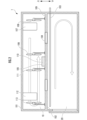
- 1 is an explanatory side plan view of a storage facility 1 according to one embodiment of the present invention.
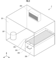
- FIG. 2 is an oblique view of a storage facility 2 according to one embodiment of the present invention.
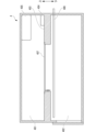
- 1 is an explanatory side plan view of a storage facility 3 according to an embodiment of the present invention.
- FIG. 1 is an explanatory side plan view of a storage facility 4 according to an embodiment of the present invention.
- FIG. 1 is an explanatory side plan view of a storage facility 5 according to an embodiment of the present invention.
- FIG. FIG. 2 is an explanatory side plan view of a refrigerated car 6 according to one embodiment of the present invention.
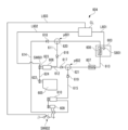
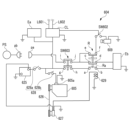
- FIG. 2 is a circuit diagram of a refrigerated car 6 according to an embodiment of the present invention.
- FIG. 2 is a circuit diagram of a refrigerated car 6 according to an embodiment of the present invention.
- FIG. 2 is a schematic diagram of a storage facility according to one embodiment of the present invention, viewed from above.
- FIG. 4 is a schematic diagram illustrating another example of an air mixer according to an embodiment of the present invention.
- Storage Figure 10A shows a schematic diagram of the storage 1 of this embodiment seen from above.
- the storage 1 of this embodiment includes a first chamber 13a having a first space 10 and a second chamber 13b having a second space 20, and the first space 10 and the second space 20 are mutually communicated via a communication mechanism 23 that mixes the air of the first space 10 and the air of the second space 20 at an arbitrary mixing ratio.
- the storage 1 includes a cooling device that is installed in the second space 20 and cools the second temperature t2 of the second space 20 to a temperature lower than the first temperature t1 of the first space 10, and a control device 12 that controls the cooling device.
- the water vapor-containing air that is partially supersaturated by cooling the high-temperature high absolute humidity air with the low-temperature low absolute humidity air is mixed at a mixing ratio on the side where fog or frost does not occur in the mixed air, near the boundary between whether or not fog or frost occurs.
- the high-temperature, high-absolute-humidity air is cooled by the low-temperature, low-absolute-humidity air, resulting in partially supersaturated water vapor-containing air.
- the air in the first space 10 and the air in the second space 20 are mixed to a mixture ratio that does not generate fog or frost. This makes it possible to humidify the second space 20 while suppressing condensation and frost in the cooling device 20 of the second space 20.
- the first space 10 is a space that supplies high-temperature, high-absolute-humidity air to the second space 20, and may have a humidifier 28.
- the first space 10 may be installed at the top of the second space 20 in the vertical direction, or at the bottom of the second space 20 in the vertical direction, or on the side of the second space 20 in the horizontal direction. Among these, the first space 10 may be installed at the top of the second space 20 in the vertical direction.
- the storage facility 1 of this embodiment may be provided with a humidifier 28 in the first space 10 and/or the second space 20. Of these, it is preferable to have a humidifier 28 in the first space 10 from the viewpoint of suppressing frost and condensation in the second space 20. This allows high-temperature, high-absolute-humidity air to be stably generated in the first space 10.
- the humidifier 28 is not particularly limited, but examples include a steam type that heats and evaporates water, an ultrasonic type that uses ultrasonic vibrations to turn water into a fine mist and supply it into the air, and an evaporation type that blows air over an absorbent that has absorbed water and humidifies the air by evaporation.
- the second space 20 may be a space in which objects to be stored are stored, and is a space in which it is desirable to maintain a low-temperature, high-humidity environment.
- objects to be stored include food such as agricultural products, livestock products, and marine products, flowers, and medical products.
- the second space 20 may have a cooling device 20, and the cooling device may cool the second temperature t2 of the second space 20 to a temperature lower than the first temperature t1 of the first space 10.
- the cooling device may have a cooling coil through which a refrigerant passes.
- the cooling coil may have fins, or may be a bare coil without cooling fins.
- the cooling coil and fins to be cooled by the refrigerant cool the inside of the storage facility 1 by exchanging heat with the gas in the storage facility 1.
- a bare coil without cooling fins is preferable. This reduces the heat transfer area of the cooling device, but minimizes the occurrence of condensation and frost on the cooling fins, thereby suppressing dehumidification from the second space 20. Therefore, the temperature can be lowered while minimizing the decrease in relative humidity.
- the cooling device 20 may have an outdoor unit that sends refrigerant to the cooling coil.
- the refrigerant adjusted to a desired temperature by the outdoor unit may circulate between the cooling coil and the outdoor unit, thereby adjusting the cooling coil to a desired temperature.
- a cooling device 20 will be referred to as a low-humidification cooling device.
- the cooling device 20 may be a dehumidifying cooling device.
- the dehumidifying cooling device has a drain mechanism that discharges water vapor that condenses on the surface of the cooling coil below the dew point outside the second chamber 13b.
- the drain mechanism There are no particular limitations on the drain mechanism, but examples include a drain mechanism that has a drain pan that collects water droplets that drip from the cooling coil and a drain hose that discharges water that accumulates in the drain pan.
- a dehumidifying cooling device is one that has a mechanism that actively discharges condensed water vapor outside the second chamber 13b.
- the cooling device 20 is a low-dehumidification cooling device. This allows the humidity in the second space 20 to be maintained at a higher level.
- the second space 20 is cooled, and as a trade-off, it is easily dehumidified, and the air therein tends to become low-temperature and relative humidity.
- the high-temperature, high-absolute-humidity air supplied from the first space 10 is mixed with the low-temperature, low-absolute-humidity air that may be held in the second space 20, and is humidified.
- the mixing ratio of high-temperature, high-absolute-humidity air and low-temperature, low-absolute-humidity air is adjusted to prevent fog or frost from forming. This makes it possible to humidify the second space 20 at the second temperature t2 of the second space 20 while suppressing condensation or frost from forming on the cooling device.
- the second space 20 (second chamber 13b) and the first space 10 (first chamber 13a) may be separated by a wall 21a and a middle door 21b, and the first chamber 13a may further have an outer door 22 that leads to the outside.
- the first chamber 13a may be an antechamber for entering the second chamber 13b.
- the wall 21a separating the second chamber 13b and the first chamber 13a may have a first ventilation hole 23a and a second ventilation hole 23b as a communication mechanism 23.
- the first ventilation hole 23a is shown as having a main function of taking in air from the first space 10 to the second space 20
- the second ventilation hole 23b is shown as having a main function of exhausting air from the second space 20 to the first space 10, but this is not limited to this.
- the first ventilation hole 23a may have both intake and exhaust functions as long as it has a function of mixing the air in the first space 10 and the air in the second space 20 at an arbitrary mixing ratio.
- the communication mechanism 23 connects the first space 10 and the second space 20 to each other, and mixes the air in the first space 10 with the air in the second space 20 at an arbitrary mixing ratio. More specifically, the high-temperature, high-absolute-humidity air that flows from the first space 10 to the second space 20 via the communication mechanism 23 is mixed with the low-temperature, low-absolute-humidity air in the second space 20, producing water vapor-containing air (mixed air).
- the form of the communication mechanism 23 is not particularly limited, but may be, for example, one or more small diameter ducts provided on the wall of the storage facility 1.
- the diameter of the small diameter duct is preferably 0.1 cm or more, 0.3 cm or more, 0.5 cm or more, 0.7 cm or more, or may be 1.0 cm or more.
- the diameter of the small diameter duct is preferably 5 cm or less, 4 cm or less, 3 cm or less, 2 cm or less, or may be 1 cm or less.
- the small diameter duct may be provided with an insect screen, dust screen, or the like to prevent the intrusion of artifacts from outside the storage facility.
- the communication mechanism 23 may be a large diameter duct of 5 cm or more.
- a second air vent 23b that connects the first space 10 and the second space 20 to each other and exhausts the air in the second space 20 to the first space 10 may be provided. This may allow gas to circulate between the first space 10 and the second space 20 by the first air vent 23a and the second air vent 23b.
- the second air vent 23b may be connected to the outside of the second space 20. This may allow gas to be supplied to the second space 20 from the first space 10 via the first air vent 23a and exhausted to the outside via the second air vent 23b.
- the control device 12 may control the cooling device to cool the second temperature t2 of the second space 20 to a temperature lower than the first temperature t1 of the first space 10, and may also control the communication mechanism 23 to mix the air of the first space 10 and the air of the second space 20 at any mixing ratio.
- the control device 12 may also adjust the humidity contained in the high-temperature, high-absolute-humidity air by controlling the humidifier.
- the communication mechanism 23 may have a shutter 29 that controls the cross-sectional area of the flow path, thereby adjusting the mixing ratio of the air in the first space 10 and the air in the second space 20.
- a control unit which will be described later, may control the shutter 29 to control the cross-sectional area of the flow path.
- the control device 12 may open the communication mechanism 23 when the cooling device in the second space 20 is stopped, and close the communication mechanism 23 when the cooling device is operating. This makes it possible to avoid a decrease in cooling capacity due to frost formation on the cooling device by supplying air while the cooling device is operating, and to suppress the consumption of cooling energy for latent heat of solidification.
- the communication mechanism 23 may also adjust the mixture ratio of the air in the first space 10 and the air in the second space 20 in conjunction with a control mechanism for the air pressure difference between the first space 10 and the second space 20.
- the control mechanism for the air pressure difference may be an exhaust mechanism and an intake mechanism provided in the first space 10 and the second space 20.
- the communication mechanism 23 may include a blower (first fan 24, second fan 26) that mixes or circulates the air in the first space 10 and the air in the second space 20. This allows the communication mechanism 23 to adjust the mixing ratio of the air in the first space 10 and the air in the second space 20 in conjunction with the blower mechanism that blows air from the first space 10 to the second space 20.
- the installation position of the blower mechanism is not particularly limited, but examples include the first fan 24 on the first space 10 side and the second fan 26 on the second space 20 side.
- the communication mechanism 23 may have an air mixer 25 on the second space 20 side. This allows the air in the first space 10 and the air in the second space 20 to be mixed in the air mixer 25, and the mixed air can be supplied from the air mixer 25 to the second space 20.
- the air in the first chamber 13a is sent to the second chamber 13b side through the first ventilation port 23a by the first fan 24.
- the air in the first chamber 13a thus sent flows into the air mixer 25 from the first ventilation port 23a.
- the air in the second chamber 13b is sent to the air mixer 25 by the second fan 26.
- the air mixer 25 the air in the second chamber 13b and the air in the first chamber 13a are mixed, and the mixed gas is sent to the second chamber 13b.
- the amount of air from the second chamber 13b supplied to the air mixer 25 can be adjusted by the second fan 26. Also, the amount of air from the first chamber 13a supplied to the air mixer 25 can be adjusted by the first fan 24. By adjusting the airflow rates of the first fan 24 and the second fan 26, the mixing ratio of the air from the second chamber 13b and the air from the first chamber 13a can be adjusted, and the humidity and temperature of the air released from the air mixer 25 can be adjusted as desired. Also, this makes it possible to humidify the inside of the second chamber 13b without causing frost, even if the temperature of the second chamber 13b is below freezing point.
- the airflow rate of the first fan 24 and the second fan 26 to adjust the mixing ratio of the air in the second chamber 13b and the air in the first chamber 13a so as to prevent fog from generating.
- the humidity difference and temperature difference can be adjusted, and the generation of fog tends to be suppressed.
- the air pressure in the second chamber 13b rises, and as a result, the efficiency of air intake into the first chamber 13a gradually decreases, making it impossible to maintain a high humidity environment.
- the air from the second chamber 13b may be sent to the first chamber 13a through the second air vent 23b. This avoids an increase in air pressure and maintains the efficiency of air intake into the first chamber 13a by the air mixer 25, and therefore the humidification efficiency.
- the second air vent 23b allows the relatively low-temperature air from the second chamber 13b to be sent to the first chamber 13a, thereby reducing the operating load of the cooling device 11 for the first chamber 13a.
- FIG. 10B shows another embodiment of the air mixer 25.
- a shutter 29 may be provided on the first chamber 13a side of the first air vent 23a.
- the shutter 29 may be either manual or electric.
- the second fan 26 may be located downstream of the air mixer 25. This allows the air in the second chamber 13b and the air in the first chamber 13a to be mixed more homogeneously by the rotation of the second fan 26.
- the internal structure of the air mixer 25 is not particularly limited as long as it is cylindrical as shown in Figs. 10A and 10B, but may have protrusions or fins, for example. This tends to generate turbulence in the air mixer 25 and promote mixing of the gases.
- the internal structure of the air mixer 25 may be configured so that the flow path through which the gas passes toward the outlet is narrowed or widened. By configuring the internal structure of the air mixer 25 so that the cross-sectional area of the flow path through which the gas passes toward the outlet is narrowed, the pressure on the mixed gas increases, and mist tends to be less likely to occur in the air mixer 25.
- the internal structure of the air mixer 25 By configuring the internal structure of the air mixer 25 so that the cross-sectional area of the flow path through which the gas passes toward the outlet is widened, the pressure on the mixed gas decreases, and the mixed air supplied from the air mixer 25 to the first chamber 13a becomes lower, so that humidification can be achieved while suppressing the temperature increase in the first chamber 13a.
- the mixing ratio of the air in the first chamber 13a and the air in the second chamber 13b is adjusted to prevent mist from occurring.
- the control device 12 may also appropriately adjust the airflow rate of the first fan 24 and the second fan 26, or the opening and closing degree of the shutter 29.
- the airflow rate of the first fan 24 may be reduced or the shutter 29 may be slightly closed to reduce the mixing ratio of the air of the first chamber 13a, or the airflow rate of the second fan 26 may be increased to increase the mixing ratio of the air of the second chamber 13b.
- a relative humidity sensor calibrated with a dew point thermometer is also installed in the second chamber 13b, and mixing by the air mixer and humidification by the humidifier are stopped when the humidity sensor indicates that the average relative humidity of the interior space is 99%.
- the relative humidity sensor value reaches the target average relative humidity of the interior space (e.g. 98% rH)
- the occurrence of fog or mist is visually confirmed through a window in the air mixer while adjusting the shutter 29, gradually reducing the intake of first chamber air and outside air from the mixture ratio at which fog occurs, and fixing the shutter 29 at a position where fog or frost no longer occurs, allowing air to be taken in from the first chamber 13a and the outside while suppressing the generation of fog.
- the operation of the cooling device and/or humidifier may be controlled so that the absolute humidity ah1 in the first space 10 is greater than the saturated water vapor amount w2 in the second space 20.
- the control device 12 may control the cooling device 11 and humidifier 28 in the second chamber 13b to adjust the temperature and humidity of the air in the first chamber 13a so that the temperature and humidity of the mixed gas do not fall below the dew point.
- the control device 12 may control the cooling device 11 in the second chamber 13b to adjust the temperature and humidity of the air in the second chamber 13b so that the temperature and humidity of the mixed gas do not fall below the dew point.
- control device 12 may control the operation of the cooling device and/or the humidifying device so that the second temperature t2 is set to any temperature in the temperature range of -3 to +3°C, and the second relative humidity rh2 is set to 90% or higher.
- the communication mechanism refers to the part that communicates between the first space 10 and the second space 20.
- partition plates 102, 104, and 109 are arranged in a row with a predetermined gap between them from approximately the center of the side wall surface of storage facility 1 in the vertical direction, and wire mesh (not shown) is installed in the gaps between partition plates 102 and 104 and between partition plates 104 and 109.
- wire mesh (not shown) is installed in the gaps between partition plates 102 and 104 and between partition plates 104 and 109.
- the first space and the second space may each be a space separated by a wall
- the storage facility of this embodiment may include a first chamber having a first space and a second chamber having a second space, which may be separated by a wall having an opening (communication mechanism).
- the wire mesh and partition plates 102, 104, 109 correspond to the communication mechanism of this embodiment.
- the contact area between the first space 10 and the second space 20 in the communication mechanism can be adjusted by the volume ratio of the first space 10 and the second space 20. For example, it is preferable that the contact area between the first space 10 and the second space 20, i.e., the opening area of the communication mechanism, corresponds to 20 to 30% of the floor area inside the storage facility.
- the communication mechanism in this embodiment may be a lattice-shaped partition plate, a communication path connecting the first space and the second space, a valve configured to compress the outside air with a compressor when the first space is outside the cabinet and send it to the second space by opening and closing the valve, or an air duct configured to send the outside air from the air duct to the second space.
- the communication mechanism may have a shielding section that can be opened and closed manually or under the control of a control device or the like depending on conditions such as the humidity inside the cabinet.
- the first space 10 is equipped with a water tank 105, air blowers 106, 108, 111, 113, and cooling devices 107, 112. Water is stored in the water tank 105, and when air is blown into the water tank 105, humidified air is generated upon contact with the water.
- the water tank 105 and air blowers 106, 111 are disposed above the partition plate 104, the air blower 113 and cooling device 112 are disposed above the partition plate 102, and the air blower 108 and cooling device 107 are disposed above the partition plate 109.
- the water tank 105, cooling devices 107, 112, and air blowers 106, 108, 111, 113 allow cooled and humidified air to circulate in the first space 10.
- the air in the first space 10 and the air in the second space 20 mix, and air convection due to the temperature difference can occur in the first space 10 and the second space 20.
- the air currents generated by the air blowers 106, 108, 111, and 113 have a higher wind speed than the convection currents, so air convection due to the temperature difference occurs only in the second space 20.
- a cooling coil 103 is installed in the upper part of the second space 20 as part of the cooling device, and cools the second space 20.
- the first space 10 may function as a humidity source for the second space 20. From this perspective, the first temperature t1 of the first space 10 may be relatively higher than the second temperature t2 of the second space 20, and the first absolute humidity ah1 of the first space 10 may be relatively higher than the second absolute humidity ah2 of the second space 20.
- the first space 10 may be in communication with the outside of the storage facility 1.
- the second space 20 may function as a space for storing the items to be stored.
- the second space 20 is cooled so that the second temperature t2 is lower than the first temperature t1, while being humidified by the air supplied from the first space 10.
- the excess water vapor contained in the air supplied from the first space 10, which becomes supersaturated, is condensed in the cooling device as frost and/or condensation. This makes it possible to prevent water droplets from adhering to the stored items while achieving cooling and humidification of the second space 20. Therefore, saturated humidity storage in the low temperature range can be achieved without concerns about contamination by water droplets, etc.
- the second space 20 may be located above the first space 10, or the first space 10 may be located on a side of the second space 20.
- the first space 10 may be provided with a first temperature detector (not shown) for detecting a first temperature t1 and a first humidity detector (not shown) for detecting a first humidity rh1.
- the second space 20 may be provided with a second temperature detector (not shown) for detecting a second temperature t2 and a second humidity detector (not shown) for detecting a second humidity rh2.
- a control device 110 is installed in the first space 10 to control the operation of the cooling devices 107 and 112, which are the first cooling device, and the cooling coil 103, which is the second cooling device, and to control the operation of the air blowers 106 and 108 to the water tank 105.
- the control device 110 is installed at the bottom of the water tank 105.
- the control device 110 may control cooling devices such as the first cooling device and the second cooling device, control a humidifier, or control a blower. As a result, the control device 110 may cool the second temperature t2 of the second space to a temperature lower than the first temperature t1 of the first space, cool the absolute humidity ah1 of the first space to a temperature lower than the absolute humidity ah2 of the second space, or control the operation of the cooling device and/or humidifier so that the absolute humidity ah1 of the first space is greater than the saturated water vapor amount w2.
- the operation of the cooling devices 107, 112 and the cooling coil 103 may be controlled to switch between on and off simultaneously, or the cooling devices 107, 112 and the cooling coil 103 may be controlled to operate independently depending on the behavior of the temperature change in the storage unit due to, for example, the volume of the storage unit.
- cooling device and the air blowing device installed in the first space 10 may be one or three or more, depending on the behavior of the temperature change of the storage facility.
- the control device 110 controls the first temperature t1 to 3 to 5°C, the second temperature t2 to -3 to +3°C, the first relative humidity rh1 to 87 to 97% RH, and the second relative humidity rh2 to 90 to 100% RH.
- the absolute humidity ah1 of the first space 10 at the first temperature t1 (3 to 5°C) is calculated to be 5.17 to 6.69 g/ m3 .
- the table below shows the temperature and the amount of saturated water vapor in the low temperature zone. As shown in the table below, the amount of saturated water vapor w2 of the second space at the second temperature t2 (-3 to +3°C) is calculated to be 4.69 to 5.02 g/ m3 .
- the storage facility 1 of this embodiment is controlled to a state in which the absolute humidity ah1 is constantly greater than the saturated water vapor amount w2, i.e., the first space 10 is constantly controlled to a state in which it contains an amount of water vapor that is greater than the saturated water vapor amount in the second space 20.
- Fruits and vegetables breathe during storage and transportation, so it is difficult to completely block water vapor with packaging.
- sea transportation takes a long time, and drying reduces the product value, especially when transported refrigerated.
- Fruits with skin can withstand low humidity for a short period of time because they secrete oils such as wax on the surface, but if stored in a low humidity environment for a long period of time, they will gradually dry out from the stem, so for long-term storage, they need to be stored at a relative humidity higher than the water activity of the flesh.
- the water activity is often 0.90 to 0.98, and in order to store them at a water activity level higher than that, it is desirable to always keep the relative humidity at saturated humidity.
- the supersaturated water that cannot be completely removed floats in the air as mist or frost inside the storage unit, but by driving the blower installed in the second space, water adhesion to the bare coil can be promoted and water adhesion to the stored items can be prevented.
- a sensor that detects the generation of mist can be installed in the second space and the operation of the blower can be controlled.
- the storage unit can be constantly maintained at saturated humidity by intermittently or continuously drawing in small amounts of outside air into the second space and periodically defrosting the bare coil with a timer.
- the storage cabinet 2 of this embodiment includes a refrigerator 201 and a low-temperature, high-humidity box 203 inside the refrigerator 201.
- the refrigerator 201 corresponds to a first space
- the low-temperature, high-humidity box 203 corresponds to a second space.
- the refrigerator 201 includes a cold air outlet 202 and a humidifier 207 inside.
- the cold air outlet 202 cools the refrigerator 201 so that the temperature of the refrigerator 201 is between 8 and 10°C.
- the humidification mechanism of the humidifier 207 is not particularly limited, but examples include ultrasonic, hybrid, and steam heating devices.
- the humidifier 207 may be equipped with a filter containing water therein and a blower that blows air to the filter, and may humidify the interior of the refrigerator 201 to a relative humidity of 80% RH to 90% RH.
- the low-temperature, high-humidity box 203 has an open top (open surface 204), and the air in the refrigerator 201 and the air in the low-temperature, high-humidity box 203 mix at the open surface 204, causing air convection due to the temperature difference in the low-temperature, high-humidity box 203.
- the open surface 204 corresponds to the communication mechanism.
- the area of the open surface 204 is 50% of the floor area of the refrigerator 201.
- a cooling coil 205 is placed on top of the low-temperature, high-humidity box 203, and the cooling coil 205 cools the low-temperature, high-humidity box 203 so that the temperature of the low-temperature, high-humidity box 203 is between -3 and +3°C.
- gas refrigerant is compressed to become high-temperature, high-pressure gas refrigerant.
- the high-temperature, high-pressure gas refrigerant sent from the compressor is cooled and condensed into medium-temperature, high-pressure liquid refrigerant.
- the medium-temperature, high-pressure liquid refrigerant sent from the condenser is decompressed, expanding and lowering its temperature, changing into low-temperature, low-pressure liquid refrigerant.
- the low-temperature, low-pressure liquid refrigerant sent from the expansion valve evaporates to become low-temperature, low-pressure gas refrigerant, and during this evaporation, the surrounding air is cooled by removing the heat of evaporation from it.
- the evaporated low-temperature, low-pressure gas refrigerant is sent to the compressor, where it is compressed again.
- first space 10 constantly contains an amount of water vapor greater than the amount of saturated water vapor in second space 20.
- Raw tuna fillets are stored at around 0°C in a low-temperature, high-humidity box 203 to consume as much ATP as possible and allow for maturation, while fresh raw fish such as wild sea bream and wild flounder can be stored in a refrigerator 201 at 9°C ⁇ 1°C to improve quality by slowing down the decomposition of ATP.
- fresh raw fish such as wild sea bream and wild flounder can be stored in a refrigerator 201 at 9°C ⁇ 1°C to improve quality by slowing down the decomposition of ATP.
- the storage 3 of this embodiment includes, from the top, a second space 302, a communication mechanism 303, and a first space 301.
- the first space 301 is provided with a humidifier 304, and the first space 301 is humidified to have a relative humidity of 80% RH to 90% RH.
- a cooling coil 305 is disposed at the top of the second space 302, and the second space 302 is cooled to have a temperature of -3 to +3°C.
- the humidifier 304 is similar to the humidifier 207 of the second embodiment, and the cooling coil 305 is similar to the cooling coil 205 of the second embodiment.
- the communication mechanism 303 is a communication passage having an opening 306 to the first space 301 and an opening 307 to the second space 302, and a blower 308 is disposed in the internal space of the communication passage.
- a wire mesh is provided in the openings 306 and 307, and the first space 301, the second space 302, and the communication mechanism 303 may be partitioned by the wire mesh and the wall of the storage facility 3.
- the air blower 308 generates an air current that circulates the air in the internal space of the communication mechanism 303.
- This air current mixes the humidified air in the first space 301 with a portion of the cooled air in the second space 302 in the open sections 306 and 307 to generate mixed air.
- the second space 302 is constantly humidified. This allows the second space 302 to be maintained in a high humidity state.
- the temperature of the first space 301 is not specifically controlled. Therefore, depending on the temperature and humidification conditions in the first space 301, an amount of water vapor exceeding the amount of saturated water vapor at -3 to +3°C may be supplied to the second space 302. In such a case, cooling occurs near the cooling coil 305, which has the lowest temperature in the second space 302, preventing frost from forming on the cooling coil 305 and causing contamination of the products by water droplets.
- a drain pan (not shown) is provided below the cooling coil 305 to melt the frost and drain the condensation.
- the first space 301 is not provided with a temperature control device including a cooling device, but depending on the overall size of the storage facility of this embodiment, the volume ratio between the first space and the second space, and the installation environment of the storage facility of this embodiment (for example, when the storage facility is installed in a cold region where the outside temperature is significantly below freezing, or in a tropical region where the outside temperature exceeds 30°C for a long period of time), the temperature difference between the first space 301 and the second space 302 may be large and the effect of this embodiment may not be fully obtained. In such cases, a temperature control device that reduces the temperature difference between the first space 301 and the second space 302 may be installed in the first space 301 as appropriate.
- the storage 4 of the fourth embodiment includes, from the top, a first space 401, a communication mechanism 403, and a second space 402.
- the first space 401 is provided with a humidifier 404, and the first space 401 is humidified to have a relative humidity of 80% RH to 90% RH.
- a cooling device 405 is arranged in the first space 401, and the first space 401 is cooled to a temperature of 14 to 16° C.
- a cooling coil 406 is arranged in the upper part of the second space 402, and the second space 402 is cooled to a temperature of 8 to 12° C.
- the humidifier 404 has a configuration similar to that of the humidifier 207 of the second embodiment, and the cooling coil 406 has a configuration similar to that of the cooling coil 205 of the second embodiment.
- the humidified air in the first space 401 is mixed with a part of the cooled air in the second space 402 to generate mixed air.
- a part of the mixed air flows into the second space 402, so the second space is humidified.
- the temperature of the second space 402 is controlled to 8 to 12°C, if an amount of water vapor exceeding the amount of saturated water vapor in that temperature range is supplied to the second space 402, condensation may occur on the cooling coil 406 instead of frost.
- a water tray (not shown) is arranged below the cooling coil 406 along the cooling coil 406, so that the condensation can be prevented from adhering to the product.
- the water tray drains the water droplets that condense to the outside of the storage 4 through the water path.
- a blower that generates air toward the cooling coil 406 may be arranged to prevent condensation from occurring on the cooling coil 406.
- the communication mechanism 403 is provided with a roof device 407 having a sliding panel that separates the first space 401 and the second space 402, a drive device (not shown) that drives the sliding panel to open and close, which opens and closes the openings of the first space 401 and the second space 402, and an operation unit (not shown) for the drive device. If excessive air flows from the first space 401 into the second space 402, the operation unit controls the sliding panel of the roof device 407 to close, thereby preventing condensation from occurring on the floor and walls of the second space 402.
- the quality of fresh raw fish such as wild sea bream and wild flounder can be improved by slowing down the decomposition of ATP, so they can be appropriately stored in the second space 402, where the interior temperature is maintained at 8 to 12°C and high humidity.
- the storage 5 of the fifth embodiment includes, from the top, a first space 501, a communication mechanism 503, and a second space 502.
- the first space 501 is provided with a humidifier 504, and the first space 501 is humidified to have a relative humidity of 80% RH to 90% RH.
- a heating device 505 is disposed in the first space 501, and the first space 501 is heated to a temperature of 58 to 62° C.
- a cooling coil 506 is disposed in the upper portion of the second space 502, and the second space 502 is cooled to a temperature of 53 to 57° C.
- the communication mechanism 503 has the same configuration as the communication mechanism 303 of the third embodiment.
- the humidified air in the first space 501 is mixed with a portion of the cooled air in the second space 502 to generate mixed air.
- a portion of the mixed air flows into the second space 502, thereby humidifying the second space 502.
- mist since the temperature of the second space 502 is controlled to 53-57°C, if an amount of water vapor exceeding the amount of saturated water vapor in that temperature range is supplied to the second space 502, the water vapor condenses and fine water droplets float in the second space 502 (hereinafter referred to as mist).
- the second discharge pipe 615 is provided with a check valve 619 between the connection p602 between the second discharge pipe 615 and the first discharge pipe 612 and the second compressor 610 to allow the refrigerant to flow from the second compressor 610 to the condenser 607.
- the switch SW602 supplies or stops power to the motor 609.
- the control box CL and the switch SW602 are connected by a signal line L603, and the switch SW602 is switched between the on and off states by a signal from the control box CL.
- FIG. 9 is an electrical circuit diagram that shows the general configuration of the electrical circuit for operating the cooling device 604.
- the cooling device 604 is equipped with an ignition switch 628, which includes a power switch 628a that turns on the main battery 625, and a starter motor drive switch 628b that drives the starting motor (starter motor (cell motor) 605a) for a predetermined time.
- an ignition switch 628 which includes a power switch 628a that turns on the main battery 625, and a starter motor drive switch 628b that drives the starting motor (starter motor (cell motor) 605a) for a predetermined time.
- the power switch 628a When the power switch 628a is turned on, the electrical system Ea and control box CL of the refrigerated car 6 are turned on.
- the starting motor (starter motor) 625a runs for a predetermined time, and the running engine 605 runs.
- the cooling device 604 includes a switch SW603 that switches the operation of the cooling device 604 between an operating state and a stopped state.
- switch SW603 When switch SW603 is turned on, it brings terminals g and h, and terminals i and j into an electrically conductive state. When switch SW603 is turned off, it brings terminals g and h, and terminals i and j into an electrically disconnected state.
- each of the component devices such as pa and pb shown in FIG. 9 represents a plug.
- plug pa When plug pa is connected to plug pb of the commercial power source PS, plug pa and plug pb are electrically connected.
- the cooling device 604 is equipped with a switching relay R that switches the electrical connection between the main battery 625 (vehicle battery) and the commercial power source PS and the motor 609 when the running engine 605 is stopped.
- the refrigerated car 6 of this embodiment is configured such that when the power switch 628a and the starting motor drive switch 628b of the ignition switch 628 are turned on, the starting motor (starter motor (cell motor)) 625a is driven for a predetermined period of time, thereby driving the running engine 605.
- the electrical system Ea and the control box CL of the cooling device 604 are controlled to be in an operational state. Therefore, the set temperature (Tth) in the luggage compartment 603 can be set by the control box CL.
- the switch SW603 when the switch SW603 is turned on after the power switch 628a of the ignition switch 628 is turned on, the induction coil 629 is energized by the power transmitted from the DC alternator 627 driven by the running engine 605 to the induction coil 629, and the contact Ra of the changeover relay R is in contact only between terminals a and b.
- the electrical system Eb of the cooling device 604 is energized, and the temperature sensor S601 is controlled to be in an operating state.
- a temperature signal (T) in the luggage compartment 603 measured by the temperature sensor S601 is sent to the control box CL via the signal line L601.
- the control box CL compares the temperature signal (T) in the luggage compartment 603 measured by the temperature sensor S601 with the set temperature (Tth) set by the control box CL, and if the temperature (T) in the luggage compartment 603 measured by the temperature sensor S601 is equal to or higher than the set temperature (Tth) set by the control box CL (T ⁇ Tth), the electromagnetic clutch 623 is connected by the switch SW601, and the first compressor 606, the condenser 607, and the evaporator 608 are driven to make the temperature in the luggage compartment 603 the set temperature (Tth) set by the control box CL.
- a temperature signal (T) in the luggage compartment 603 measured by the temperature sensor S601 is sent to the control box CL via the signal line L601.
- the control box CL compares the temperature signal (T) in the luggage compartment 603 measured by the temperature sensor S601 with the set temperature (Tth) set by the control box CL.
- the switch SW601 turns off the electromagnetic clutch 623, and the first compressor 606 is stopped, so that the condenser 607 and the evaporator 608 are controlled to be in the stopped state.
- the temperature (T) inside the luggage compartment 603 is substantially maintained at the set temperature (Tth) set by the control box CL.
- the electrical system E and control box CL of the refrigerated car 6 are controlled to be in an operational state. This allows the control box CL to set the set temperature (Tth) in the luggage compartment 603.
- the temperature signal (T) is compared with the set temperature (Tth) set by the control box CL, and if the temperature (T) inside the luggage compartment 603 measured by the temperature sensor S601 is equal to or higher than the set temperature (Tth) set by the control box CL (T ⁇ Tth), the switch SW602 is turned on, the first compressor 606, the condenser 607, and the evaporator 608 are driven, and the temperature inside the luggage compartment 603 is controlled to the set temperature (Tth) set by the control box CL.
- this cooling device 604 even if the refrigerated car 6 of this embodiment is stopped or parked, when the power switch 628a of the ignition switch 628 is on, the plug pa is connected to the plug pb of the commercial power source PS, and the switch SW603 is on, a temperature signal (T) in the luggage compartment 603 measured by the temperature sensor S601 is sent to the control box CL via the signal line L601, and the control box CL detects the temperature in the luggage compartment 603 measured by the temperature sensor S601. The temperature signal (T) is compared with the set temperature (Tth) set by the control box CL.
- the switch SW602 turns off, the first compressor 606, the condenser 607, and the evaporator 608 are stopped, and the temperature inside the luggage compartment 603 is controlled to the set temperature (Tth) set by the control box CL.
- the temperature (T) inside the luggage compartment 603 is substantially maintained at the set temperature (Tth) set by the control box CL.
- the cooling device 604 when it is desired to stop the cooling device 604 while the refrigerated vehicle 6 of this embodiment is stopped or parked (i.e., while the driving engine 605 is stopped), by disconnecting the plug pa from the plug pb of the commercial power source PS, the power transmission from the commercial power source PS to the cooling device 604 and the motor 609 is cut off, and the cooling device 604 is stopped.
- the cooling device 604 when it is desired to stop the cooling device 604 while the refrigerated vehicle 6 of this embodiment is stopped or parked (the driving engine 605 is stopped), by turning off the switch SW603, the power transmission from the commercial power source PS to the cooling device 604 and the motor 609 is cut off, even if the plug pa is connected to the plug pb of the commercial power source PS, and the cooling device 604 is stopped.
- the vehicle may be provided with a secondary battery 630 that is configured to be charged by the DC alternator 627 when the driving engine 605 is operating.
- the secondary battery, the second compressor 610, etc. drive the cooling device 604, and the interior of the luggage compartment 603 is controlled to a predetermined temperature.
- the power transmission form of the cooling device 604 is the same as that of the humidifier (air blowers 106, 108 to the water tank 105 in the first embodiment) and the control device (control device 110 in the first embodiment).
- tubular objects such as food for long periods in the storage facility 1 of the first embodiment in a cool transport container or the like and then transporting them in the refrigerated vehicle 6 of the sixth embodiment, the tubular objects can be stored and transported while maintaining the appropriate temperature and humidity for storing the objects.
- a transport cool container may be used that is equipped with a generator as an auxiliary power source for operating the cooling circuit and that auxiliary maintains the appropriate temperature and humidity for preserving the stored goods.
- the container may be a water-resistant paper container with a vent hole for allowing cool air into the container and for packaging the items to be cooled inside the container, and may also be provided with a water-absorbent sheet or the like inside the container to absorb and retain moisture generated inside the container.
- the first space may be an intake duct for taking in outside air into the second space, or the first space may not be provided as an internal space, with only the second space being the internal space, and high absolute humidity outside air may be taken into the second space.
- the cabinet may be configured to heat, cool, humidify, or dehumidify the air taken into the internal space from the external space depending on the temperature and humidity conditions of the external space.
- the cooling device installed in the second space in this embodiment is preferably a metal coil.
- Metal coils have a large surface area in contact with the air, which makes frosting efficient and easy to defrost.
- the humidifier installed in the first space in this embodiment may be controlled to stop the humidification operation if there is a lot of frost and/or condensation on the cooling device in the second space.
- a mass sensor module is placed on the cooling coil 103 to measure the amount of frost on the cooling coil 103.
- a possible configuration is that when the amount of frost exceeds a predetermined amount, the operation of the air blower 106 and the air blower 111 are controlled to stop.
- the storage facility and delivery system of this embodiment can be used for long-term storage of agricultural produce and dry-aging of meat, and can suppress deterioration of food quality.
- an internal temperature of 0-4°C and an internal relative humidity of 70-90% are suitable, while for dry-aging meat, which has a higher water activity than agricultural produce, an internal temperature of 0-4°C and an internal relative humidity of 80-90% are suitable.
- the delivery system of this embodiment can maintain low temperature and high humidity conditions appropriate for the food in both storage and delivery states, making a meaningful contribution to long-term storage of agricultural produce and dry-aging of meat.
Landscapes
- Engineering & Computer Science (AREA)
- Chemical & Material Sciences (AREA)
- Combustion & Propulsion (AREA)
- Physics & Mathematics (AREA)
- Mechanical Engineering (AREA)
- Thermal Sciences (AREA)
- General Engineering & Computer Science (AREA)
- Cold Air Circulating Systems And Constructional Details In Refrigerators (AREA)
Priority Applications (1)
| Application Number | Priority Date | Filing Date | Title |
|---|---|---|---|
| JP2025555061A JPWO2025095083A1 (https=) | 2023-11-02 | 2024-10-31 |
Applications Claiming Priority (2)
| Application Number | Priority Date | Filing Date | Title |
|---|---|---|---|
| JP2023188144 | 2023-11-02 | ||
| JP2023-188144 | 2023-11-02 |
Publications (1)
| Publication Number | Publication Date |
|---|---|
| WO2025095083A1 true WO2025095083A1 (ja) | 2025-05-08 |
Family
ID=95580846
Family Applications (1)
| Application Number | Title | Priority Date | Filing Date |
|---|---|---|---|
| PCT/JP2024/038959 Pending WO2025095083A1 (ja) | 2023-11-02 | 2024-10-31 | 高湿度保管庫 |
Country Status (2)
| Country | Link |
|---|---|
| JP (1) | JPWO2025095083A1 (https=) |
| WO (1) | WO2025095083A1 (https=) |
Citations (6)
| Publication number | Priority date | Publication date | Assignee | Title |
|---|---|---|---|---|
| JPS6163624U (https=) * | 1984-09-28 | 1986-04-30 | ||
| JP2000346535A (ja) * | 1999-06-09 | 2000-12-15 | Ke Corporation:Kk | 冷蔵車 |
| JP2004299800A (ja) * | 2003-03-28 | 2004-10-28 | Jfe Steel Kk | 低温倉庫およびそこに保管された物資の出庫方法 |
| JP2009008326A (ja) * | 2007-06-28 | 2009-01-15 | Sharp Corp | 冷蔵庫および冷蔵庫の加湿方法 |
| JP3236249U (ja) * | 2021-12-08 | 2022-02-07 | フーズテック株式会社 | 恒温恒湿コンテナ |
| JP2023125868A (ja) * | 2022-02-28 | 2023-09-07 | 株式会社Zero Food | 前室構造体及び保管庫とその制御システム |
-
2024
- 2024-10-31 JP JP2025555061A patent/JPWO2025095083A1/ja active Pending
- 2024-10-31 WO PCT/JP2024/038959 patent/WO2025095083A1/ja active Pending
Patent Citations (6)
| Publication number | Priority date | Publication date | Assignee | Title |
|---|---|---|---|---|
| JPS6163624U (https=) * | 1984-09-28 | 1986-04-30 | ||
| JP2000346535A (ja) * | 1999-06-09 | 2000-12-15 | Ke Corporation:Kk | 冷蔵車 |
| JP2004299800A (ja) * | 2003-03-28 | 2004-10-28 | Jfe Steel Kk | 低温倉庫およびそこに保管された物資の出庫方法 |
| JP2009008326A (ja) * | 2007-06-28 | 2009-01-15 | Sharp Corp | 冷蔵庫および冷蔵庫の加湿方法 |
| JP3236249U (ja) * | 2021-12-08 | 2022-02-07 | フーズテック株式会社 | 恒温恒湿コンテナ |
| JP2023125868A (ja) * | 2022-02-28 | 2023-09-07 | 株式会社Zero Food | 前室構造体及び保管庫とその制御システム |
Also Published As
| Publication number | Publication date |
|---|---|
| JPWO2025095083A1 (https=) | 2025-05-08 |
Similar Documents
| Publication | Publication Date | Title |
|---|---|---|
| US7966842B2 (en) | Refrigerator, and electric device | |
| JP4619379B2 (ja) | 冷蔵庫 | |
| JP2009121803A (ja) | 冷蔵庫 | |
| JP2004360948A (ja) | 冷蔵庫 | |
| CN205536801U (zh) | 冷冻冷藏箱 | |
| WO2015176581A1 (zh) | 冰箱 | |
| KR20150098339A (ko) | 저온저장고 및 그 제어방법 | |
| WO2015172610A1 (zh) | 冰箱 | |
| JP2000346524A (ja) | 貯蔵庫 | |
| CN102287998A (zh) | 冰箱 | |
| WO2025095083A1 (ja) | 高湿度保管庫 | |
| CN116045578A (zh) | 冰箱 | |
| JP7573302B2 (ja) | 冷蔵室 | |
| CN210441512U (zh) | 一种风冷冰箱精确增湿装置 | |
| JPH09126623A (ja) | 食品貯蔵庫 | |
| JP2582994B2 (ja) | 高鮮度冷蔵システム | |
| JP4641684B2 (ja) | 解凍装置 | |
| KR101775274B1 (ko) | 절전형 저온저장고 | |
| CN210463715U (zh) | 一种风冷冰箱化霜增湿装置 | |
| JPH10311649A (ja) | 食品用冷凍庫およびその運転制御方法 | |
| WO2025105202A1 (ja) | 加湿冷却システム | |
| JP6683648B2 (ja) | 庫内環境調節装置及び食物熟成装置 | |
| JP5320794B2 (ja) | 冷蔵庫 | |
| JPH0541344Y2 (https=) | ||
| CN208765345U (zh) | 气调冷库 |
Legal Events
| Date | Code | Title | Description |
|---|---|---|---|
| 121 | Ep: the epo has been informed by wipo that ep was designated in this application |
Ref document number: 24885849 Country of ref document: EP Kind code of ref document: A1 |
|
| ENP | Entry into the national phase |
Ref document number: 2025555061 Country of ref document: JP Kind code of ref document: A |
|
| WWE | Wipo information: entry into national phase |
Ref document number: 2025555061 Country of ref document: JP |