WO2025083774A1 - エジェクタ及びこれを用いた熱分解炭化処理装置 - Google Patents
エジェクタ及びこれを用いた熱分解炭化処理装置 Download PDFInfo
- Publication number
- WO2025083774A1 WO2025083774A1 PCT/JP2023/037518 JP2023037518W WO2025083774A1 WO 2025083774 A1 WO2025083774 A1 WO 2025083774A1 JP 2023037518 W JP2023037518 W JP 2023037518W WO 2025083774 A1 WO2025083774 A1 WO 2025083774A1
- Authority
- WO
- WIPO (PCT)
- Prior art keywords
- carbonization
- section
- chamber
- combustion chamber
- air
- Prior art date
- Legal status (The legal status is an assumption and is not a legal conclusion. Google has not performed a legal analysis and makes no representation as to the accuracy of the status listed.)
- Pending
Links
Images






Classifications
-
- F—MECHANICAL ENGINEERING; LIGHTING; HEATING; WEAPONS; BLASTING
- F04—POSITIVE - DISPLACEMENT MACHINES FOR LIQUIDS; PUMPS FOR LIQUIDS OR ELASTIC FLUIDS
- F04F—PUMPING OF FLUID BY DIRECT CONTACT OF ANOTHER FLUID OR BY USING INERTIA OF FLUID TO BE PUMPED; SIPHONS
- F04F5/00—Jet pumps, i.e. devices in which flow is induced by pressure drop caused by velocity of another fluid flow
- F04F5/14—Jet pumps, i.e. devices in which flow is induced by pressure drop caused by velocity of another fluid flow the inducing fluid being elastic fluid
- F04F5/16—Jet pumps, i.e. devices in which flow is induced by pressure drop caused by velocity of another fluid flow the inducing fluid being elastic fluid displacing elastic fluids
-
- C—CHEMISTRY; METALLURGY
- C10—PETROLEUM, GAS OR COKE INDUSTRIES; TECHNICAL GASES CONTAINING CARBON MONOXIDE; FUELS; LUBRICANTS; PEAT
- C10B—DESTRUCTIVE DISTILLATION OF CARBONACEOUS MATERIALS FOR PRODUCTION OF GAS, COKE, TAR, OR SIMILAR MATERIALS
- C10B53/00—Destructive distillation, specially adapted for particular solid raw materials or solid raw materials in special form
- C10B53/02—Destructive distillation, specially adapted for particular solid raw materials or solid raw materials in special form of cellulose-containing material
-
- C—CHEMISTRY; METALLURGY
- C10—PETROLEUM, GAS OR COKE INDUSTRIES; TECHNICAL GASES CONTAINING CARBON MONOXIDE; FUELS; LUBRICANTS; PEAT
- C10L—FUELS NOT OTHERWISE PROVIDED FOR; NATURAL GAS; SYNTHETIC NATURAL GAS OBTAINED BY PROCESSES NOT COVERED BY SUBCLASSES C10G OR C10K; LIQUIFIED PETROLEUM GAS; USE OF ADDITIVES TO FUELS OR FIRES; FIRE-LIGHTERS
- C10L5/00—Solid fuels
- C10L5/40—Solid fuels essentially based on materials of non-mineral origin
- C10L5/44—Solid fuels essentially based on materials of non-mineral origin on vegetable substances
-
- F—MECHANICAL ENGINEERING; LIGHTING; HEATING; WEAPONS; BLASTING
- F04—POSITIVE - DISPLACEMENT MACHINES FOR LIQUIDS; PUMPS FOR LIQUIDS OR ELASTIC FLUIDS
- F04F—PUMPING OF FLUID BY DIRECT CONTACT OF ANOTHER FLUID OR BY USING INERTIA OF FLUID TO BE PUMPED; SIPHONS
- F04F5/00—Jet pumps, i.e. devices in which flow is induced by pressure drop caused by velocity of another fluid flow
- F04F5/02—Jet pumps, i.e. devices in which flow is induced by pressure drop caused by velocity of another fluid flow the inducing fluid being liquid
- F04F5/04—Jet pumps, i.e. devices in which flow is induced by pressure drop caused by velocity of another fluid flow the inducing fluid being liquid displacing elastic fluids
-
- F—MECHANICAL ENGINEERING; LIGHTING; HEATING; WEAPONS; BLASTING
- F04—POSITIVE - DISPLACEMENT MACHINES FOR LIQUIDS; PUMPS FOR LIQUIDS OR ELASTIC FLUIDS
- F04F—PUMPING OF FLUID BY DIRECT CONTACT OF ANOTHER FLUID OR BY USING INERTIA OF FLUID TO BE PUMPED; SIPHONS
- F04F5/00—Jet pumps, i.e. devices in which flow is induced by pressure drop caused by velocity of another fluid flow
- F04F5/44—Component parts, details, or accessories not provided for in, or of interest apart from, groups F04F5/02 - F04F5/42
- F04F5/48—Control
-
- F—MECHANICAL ENGINEERING; LIGHTING; HEATING; WEAPONS; BLASTING
- F23—COMBUSTION APPARATUS; COMBUSTION PROCESSES
- F23G—CREMATION FURNACES; CONSUMING WASTE PRODUCTS BY COMBUSTION
- F23G5/00—Incineration of waste; Incinerator constructions; Details, accessories or control therefor
- F23G5/44—Details; Accessories
-
- Y—GENERAL TAGGING OF NEW TECHNOLOGICAL DEVELOPMENTS; GENERAL TAGGING OF CROSS-SECTIONAL TECHNOLOGIES SPANNING OVER SEVERAL SECTIONS OF THE IPC; TECHNICAL SUBJECTS COVERED BY FORMER USPC CROSS-REFERENCE ART COLLECTIONS [XRACs] AND DIGESTS
- Y02—TECHNOLOGIES OR APPLICATIONS FOR MITIGATION OR ADAPTATION AGAINST CLIMATE CHANGE
- Y02E—REDUCTION OF GREENHOUSE GAS [GHG] EMISSIONS, RELATED TO ENERGY GENERATION, TRANSMISSION OR DISTRIBUTION
- Y02E50/00—Technologies for the production of fuel of non-fossil origin
- Y02E50/10—Biofuels, e.g. bio-diesel
Definitions
- the present invention relates to an ejector that can increase the suction force relative to the blowing capacity with a simple configuration, and a pyrolysis carbonization treatment device that uses the ejector.
- organic waste (hereinafter referred to simply as "materials to be carbonized”) is generated daily by various industries, including various manufacturing sectors, the livestock industry, sewage treatment plants, and medical institutions.
- the treatment must be done in accordance with certain standards while taking into consideration the environment, which has placed a heavy burden on these industries.
- This type of carbonization processing device is equipped with a combustion chamber that generates hot air, and a box-shaped carbonization chamber that is surrounded on five sides, excluding the door section, by a snake-shaped heat flow path through which the hot air flows.
- the hot air is circulated throughout the entire heat flow path, and the objects to be carbonized placed in the carbonization chamber are indirectly heated from outside the carbonization chamber to carbonize them.
- the vaporized water vapor and distillation gases that are decomposed in the carbonization chamber are supplied to the combustion chamber and burned, preventing the release of harmful distillation gases into the atmosphere and also performing deodorization processing.
- an ejector was installed in the carbonized gas transfer pipe connecting the carbonization chamber and the combustion chamber, and the air supplied by the blower was used as the driving flow to suck in the vaporized material containing the carbonized gas in the carbonization chamber and discharge it into the combustion chamber.
- this ejector discharges air supplied from a blower with normal blowing capacity as a driving flow through a nozzle, and sucks in the dry distillation gas sent to the outer periphery of the nozzle.
- the suction force of the dry distillation gas is small compared to the blowing capacity of the air, and it takes a long time to exhaust the dry distillation gas, which results in a long pyrolysis carbonization process time.
- the ejector according to the present invention includes an introduction section whose inner cross-sectional area gradually increases toward the downstream side to introduce driving-flow air, a curved section which is a curved circular tube connected to the downstream end of the introduction section, an acceleration section which is connected to the downstream end of the curved section and whose inner cross-sectional area gradually decreases to accelerate the driving-flow air, a junction section which is a circular tube connected to the downstream end of the acceleration section, and a suction tube which is a circular tube that coincides with the central axis of the junction section and has a smaller diameter than the diameter of the downstream end of the acceleration section, penetrates from the outside of the outer wall of the curved section, which has a larger diameter, into the inside of the curved section, and has a tip opening located upstream of the downstream end of the acceleration section, and is characterized in that the driving-flow air is accelerated in the acceleration section between the inner wall of the acceleration section and the outer wall of the tip of the suction tube, the
- the pyrolysis carbonization treatment apparatus includes a combustion chamber which generates hot air, a carbonization chamber which is housed in a carbonization furnace case and inside which an object to be carbonized is housed, a heat flow path is formed in a heat flow path layer between the inner surface of the carbonization furnace case and the outer peripheral side surface of the carbonization chamber, the object to be carbonized is indirectly heated by hot air introduced from the combustion chamber through a hot air supply passage which is connected to the combustion chamber, and pyrolyzed into vaporized and non-vaporized material, the hot air is discharged to the outside air, and the vaporized material is suctioned through a dry distillation gas transfer pipe which connects the carbonization chamber and the combustion chamber.
- a pyrolysis carbonization treatment device equipped with a carbonization treatment device main body capable of discharging into the combustion chamber, the ejector described in claim 1 is disposed in the middle of the dry distillation gas transfer pipe, the downstream side of the dry distillation gas transfer pipe on the carbonization chamber side is the suction pipe, driving flow air supplied from an air blower is introduced into the introduction section, automatic opening and closing valves whose opening degree can be adjusted are provided on the upstream side of the suction pipe and the upstream side of the introduction section, and the vaporized material containing the dry distillation gas is sucked in, and a fluid in which the driving flow air and the vaporized material are mixed can be supplied to the combustion chamber.
- the pyrolysis treatment device according to the present invention is characterized in that, in the above invention, a bellows is interposed at least in the piping of the hot air supply passage connected to the carbonization treatment device main body.
- the heat flow path is formed in a heat flow path layer between the inner surface of the carbonization furnace case and the five outer peripheral sides excluding the entrance/exit side of the carbonization chamber for the object to be carbonized
- the carbonization furnace case has an opening and a door section at the entrance/exit side for the object to be carbonized
- a top shaft that is operated vertically and horizontally by a hydraulic cylinder is arranged on the peripheral surface of the opening of the carbonization furnace case, and tapered tops are arranged discretely on the top shaft
- a door section top is arranged in a position corresponding to the tapered top, with a sloping surface formed in the opposite direction to the sloping surface of the tapered top, and when the door section is closed, the sloping surface of the tapered top and the sloping surface of the door section top slide in the opposing direction due to the pressure of the top shaft by the hydraulic cylinder, so that the door section is in
- the pyrolysis treatment device in the above invention, has a combustion chamber temperature control mode for controlling the temperature of the carbonization chamber by controlling the amount of fuel supplied to the combustion chamber, and a carbonization gas control mode for fixing the amount of fuel supplied to the combustion chamber to a minimum amount to serve as a pilot light for the combustion chamber, and for controlling the temperature of the carbonization chamber by adjusting the amount of air and carbonization gas supplied from the ejector to the combustion chamber, and is characterized in that it is equipped with a control device that controls the temperature of the carbonization chamber in the carbonization gas control mode when the carbonization gas is generated in the carbonization chamber, and controls the temperature of the carbonization chamber in the combustion chamber temperature control mode when the carbonization gas is not generated.
- the present invention makes it possible to increase the suction force relative to the air blowing capacity with a simple configuration.
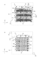
- FIG. 1 is a schematic diagram showing the overall configuration of a pyrolysis carbonization treatment apparatus according to the present embodiment.
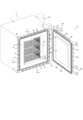
- FIG. 2 is a front view showing the appearance of the pyrolysis carbonization treatment apparatus.
- FIG. 3 is a cross-sectional plan view of the pyrolysis carbonization treatment apparatus.
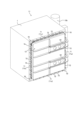
- FIG. 4 is a perspective view of the configuration of the heat flow path surrounding the coking chamber, as viewed from above on one side.
- FIG. 5 is a perspective view showing the configuration of the heat flow path surrounding the coking chamber as viewed from below on the other side.
- FIG. 6 is a perspective view showing the carbonization tray installed in the carbonization chamber 2. As shown in FIG. FIG. 7 shows a side view and a front view of a carbonization tray.
- FIG. 7 shows a side view and a front view of a carbonization tray.
- FIG. 8 is an explanatory diagram showing the overall configuration of the combustion chamber and the generation state of a swirling flow of hot air inside the combustion chamber.
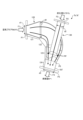
- FIG. 9 is a cross-sectional view in which a part of the configuration of the ejector is cut away.
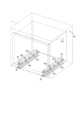
- FIG. 10 is a perspective view showing a mounting structure when the carbonization chamber is accommodated in the carbonization furnace case.
- FIG. 11 is a side view of the mounting structure when the carbonization chamber is accommodated in the carbonization furnace case.
- FIG. 12 is a perspective view showing a trailer and a tractor before the pyrolysis carbonization treatment device is mounted, and a perspective view showing a carbonization treatment vehicle equipped with the pyrolysis carbonization treatment device.
- FIG. 10 is a perspective view showing a mounting structure when the carbonization chamber is accommodated in the carbonization furnace case.
- FIG. 11 is a side view of the mounting structure when the carbonization chamber is accommodated in the carbonization furnace case.
- FIG. 12 is a perspective view showing a trailer and
- FIG. 13 is a cross-sectional view, partly broken away, showing the structure of the bellows.
- FIG. 14 is a diagram showing the structure of the carbonization device main body with the door closed.
- FIG. 15 is a diagram showing the structure of the carbonization device main body with the door open.
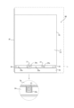
- FIG. 16 is a diagram showing the sealing structure on the front side of the carbonization furnace case.
- FIG. 17 is a cross-sectional view of the carbonization apparatus main body shown in FIG. 16 taken along the line AA.
- FIG. 18 is a diagram showing the engagement relationship between the door portion piece of the door portion and the tapered piece of the carbonization furnace case.
- FIG. 19 is a diagram showing the change over time in the temperature of the carbonization chamber when the control device controls the pyrolysis carbonization process.
- FIG. 14 is a diagram showing the structure of the carbonization device main body with the door closed.
- FIG. 15 is a diagram showing the structure of the carbonization device main body with the door open.
- FIG. 16 is
- FIG. 20 is a diagram comparing the amount of heat contained in superheated steam and hot air.
- FIG. 21 is an explanatory diagram for explaining the concept of the combustion control mode performed by the control device.
- FIG. 22 is a flowchart showing the procedure of the pyrolysis carbonization process performed by the control device (part 1).
- FIG. 23 is a flowchart showing the procedure of the pyrolysis carbonization process performed by the control device (part 2).
- FIG. 24 is a flowchart showing the procedure of pyrolysis carbonization processing by the control device (part 3).
- FIG. 1 is a schematic diagram showing the overall configuration of the pyrolysis carbonization treatment device 100 according to this embodiment.
- FIG. 2 is a front view showing the appearance of the pyrolysis carbonization treatment device 100.
- FIG. 3 is a plan sectional view of the pyrolysis carbonization treatment device 100.
- FIG. 4 is a perspective view of the configuration of the heat flow path 4 surrounding the carbonization chamber 2, viewed from above on one side.
- FIG. 5 is a perspective view of the configuration of the heat flow path 4 surrounding the carbonization chamber 2, viewed from below on the other side.
- the pyrolysis carbonization treatment device 100 is equipped with a combustion chamber 6 that generates hot air in the center, and two carbonization chambers 2, 2' that are surrounded on the outer periphery except for the front by heat flow path layers 3, 3' through which hot air circulates at both upper ends of the combustion chamber 6.
- the hot air is blown and circulated throughout the entire heat flow path layers 3, 3' to indirectly heat and carbonize the object to be carbonized contained in the carbonization chambers 2, 2' from outside the carbonization chambers 2, 2'.
- the heat flow path layer 3 has a heat flow path 4 with a snake-shaped structure, which circulates hot air regularly around the outer periphery of the carbonization chambers 2 and 2' to effectively transfer heat energy to the object to be carbonized inside the carbonization chambers 2 and 2'.
- this heat flow path 4 is not a simple snake-shaped structure that surrounds the outer periphery of the carbonization chamber 2, but is divided into two heat flow paths 4a and 4b on the outer periphery of one carbonization chamber 2, and the heat flow paths 4a and 4b are formed in a zigzag pattern according to a certain rule on the five sides of the carbonization chamber 2 from the upstream side to the downstream side of each.
- the beginning of the first flow path 4a and the beginning of the second flow path 4b both communicate with and merge into the terminal opening 5b of the hot air supply path 5 from the combustion chamber 6, which opens into one side 2a of the carbonization chamber 2, and as shown in FIG. 5, the end of the first flow path 4a and the end of the second flow path 4b both communicate with and merge into the beginning opening 10c of the hot air exhaust path 10, which is provided on one side 2a of the carbonization chamber 2 opposite the end opening of the hot air supply path 5, forming a zigzag shape and partitioning each flow path by multiple partitions 41.
- the first flow path 4a and the second flow path 4b are partitioned by a dividing wall 40 provided on one side 2a of the carbonization chamber 2 at a position that halves the terminal opening 5b of the hot air inlet pipe 5a.
- the first flow path 4a is formed by a first flow path upstream section 4a-1 formed on one side surface 2a of the carbonization chamber 2, a first flow path midstream section 4a-2 formed on the top surface 2b of the carbonization chamber 2, and a first flow path downstream section 4a-3 formed on the other side surface 2c of the carbonization chamber 2.
- the second flow path 4b is formed by a second flow path upstream portion 4b-1 formed on the back surface 2d of the carbonization chamber 2 and a second flow path downstream portion 4b-2 formed on the bottom surface 2e of the carbonization chamber 2.
- the first flow path 4a and the second flow path 4b are connected at the beginning and end of each flow path section on the upstream and downstream sides, respectively.
- the ends of the first flow path 4a and the second flow path 4b are configured to join at the opening 10c at the beginning of the exhaust pipe 10a, which is the hot air exhaust path 10, and connect to the side wall 6d opposite the side surface 2a on which the flow dividing wall 40 of the carbonization chamber 2 is provided.
- the hot air flows through these zigzag heat flow paths 4a, 4b, so that the thermal energy of the hot air is transferred extremely effectively and efficiently to the object C to be carbonized inside the carbonization chambers 2, 2'.
- the carbonization chambers 2, 2' which are in a high-temperature state, can be rapidly cooled, preventing uneven distortion and deterioration caused by thermal spots in the carbonization chambers 2, 2' while achieving uniform thermal contraction of the side walls of the carbonization chambers 2, 2'.
- the pyrolysis carbonization processing device 100 which can be mounted on a vehicle using this indirect heating method, is provided with heat flow paths 4a, 4b in the carbonization chambers 2, 2' that dramatically increase the heat exchange rate, such as heating or cooling, between the heat transfer fluid or refrigerant fluid, according to a certain regularity, preventing adverse effects that occur during heat exchange.
- the carbonization chamber 2 is formed in a box shape and is housed in a carbonization furnace case 1 that is similar in shape to the carbonization chamber 2.
- the carbonization furnace case 1 and the carbonization chamber 2 are nested together, and a heat flow path layer 3 is formed between the inner surface of the carbonization furnace case 1 and the five outer peripheral sides of the carbonization chamber 2, excluding the entrance/exit 2f for the material to be carbonized, with the outer periphery blocked by an outer plate 3a to block out the outside air, and a zigzag heat flow path 4 is formed in this heat flow path layer 3.
- a certain gap is formed between the outer plate 3a of the heat flow path layer 3 and the inner plate of the carbonization furnace case 1 to form an insulating air layer 80.
- an insulating air layer 80 is formed between the carbonization furnace case 1 and the carbonization chamber 2 housed inside it in a nested structure, i.e., the outer plate 3a of the heat flow path layer 3, and between the door portion 12 and the other peripheral side surfaces excluding the bottom surface.
- the inside of the wall thickness of the carbonization furnace case 1 is filled with ceramic wool 81 as an insulating material.
- the carbonization chamber 2 has a space inside for storing the objects C to be carbonized, and a front opening 2f for objects to be carbonized that allows the objects C to be loaded into the carbonization chamber and collected, and a door is pivoted at the carbonization chamber 2f for objects to be carbonized so that it can be opened and closed freely.
- the inside of the door section 12 is filled with a heat insulating material such as ceramic wool 81, as shown in Figure 3.
- a heat insulating material such as ceramic wool 81, as shown in Figure 3.
- several sheets of ceramic wool 81 are stacked and secured together with through bolts or the like.
- the carbonization chamber 2 is connected to the combustion chamber 6 via a carbonization gas transfer pipe 7 at the upper central part of one side surface 2a, and the carbonization gas generated in the carbonization chamber 2 is returned to the combustion chamber 6 to improve combustion efficiency.
- the object C to be carbonized is stored, such as waste lumber or everyday items made of organic materials. For this reason, a storage mechanism 90 for the object C to be carbonized is stored in the carbonization chamber 2 so that it can be easily removed.
- the storage mechanism 90 to be stored in the carbonization chamber 2 will be specifically described with reference to Figs. 3, 6, and 7.
- the storage mechanism 90 is configured as a square box-shaped carbonization tray 20.
- Fig. 6 is a perspective view showing the state in which the carbonization tray 20 is inserted and installed in the carbonization chamber 2.
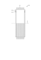
- Fig. 7(a) is a side view showing the configuration of the carbonization tray 20, and
- Fig. 7(b) is a front view showing the configuration of the carbonization tray 20.
- the carbonization tray 20 is formed in a rectangular shape that is slightly smaller than the internal space of the carbonization chamber 2, and is a box-shaped frame that opens upward.
- the peripheral walls and bottom surface of the rectangular assembled frame are made of wire mesh 20a, and legs 20b protrude from the four corners of the bottom frame 20c.
- a space S is formed between the upper and lower tiers of carbonization trays 20 through the legs 20b.
- the storage mechanism 90 for the carbonization objects C stored in the carbonization chamber 2 is configured as a rectangular box that is open at the top, with at least the sides formed of wire mesh 20a, and legs 20b protruding from the four corners of the outer bottom so that when stacked on top of each other, a gap S is formed between the lower storage mechanism 90 so that a lift claw can be inserted, and the carbonization objects C stored in the storage mechanism 90 in the carbonization chamber 2 are irradiated with radiant heat as uniformly, quickly, and evenly as possible.
- the carbonization target C stored in the storage mechanism 90 in the carbonization chamber 2 is irradiated with radiant heat as uniformly, quickly, and evenly as possible, and is efficiently carbonized.
- the storage mechanism 90 has a stacked structure, radiant heat is radiated efficiently.
- the legs 20b form a flow path for hot air between the upper and lower storage mechanisms 90, and at the same time, the hot air that has passed through the wire mesh 20a of the side wall rises and flows upward from the wire mesh 20a at the bottom of the upper storage mechanism, forming an efficient flow of hot air (dashed arrow in the figure), and the hot air flows efficiently through the gaps between the irregularly shaped carbonization objects C that are stacked in an arbitrary and random order, and the hot air comes into contact with as much of the entire surface of the irregularly shaped carbonization objects C as possible, making the carbonization process more efficient.
- the carbonization tray 20 configured in this manner stores and stacks the object C to be carbonized at the bottom so that it surrounds the outer periphery of the hot gas convection cylinder 20d from its top opening, thereby increasing the contact area between the object C to be carbonized, the bottom, and the hot gas convection cylinder 20d, and further improving the radiant heat efficiency and hot gas convection efficiency inside the carbonization chamber 2 during heating, thereby creating an effective thermal decomposition environment for the object C to be carbonized.
- Figure 8(a) is an explanatory diagram showing the overall configuration of the combustion chamber 6
- Figure 8(b) is an explanatory diagram showing the generation state of a swirling flow of hot air inside the combustion chamber 6.
- the combustion chamber 6 is rectangular and is arranged so that it is sandwiched between two carbonization furnace cases 1, one at the front and one at the back, which are placed on the trailer 31.
- a burner 61 for generating hot air is provided in the approximate center of the front wall 6a of the combustion chamber 6, dry distillation gas transfer pipes 7, 7' protrude into the combustion chamber 6 from the front position of the upper wall 6b of the combustion chamber 6, two hot air inlet pipes 5a, 5a' and a hot air blower section 62 communicating with the upper part are disposed in the rear position of the upper wall 6b of the combustion chamber 6, and a mixed combustion section 63 is formed behind the hot air blower section 62.
- the outer periphery of the combustion chamber 6 is surrounded by a heat-resistant wall 64 made of a fire-resistant material, such as fireproof tiles or ceramic wool, as shown in FIG. 1.
- the burner 61 uses kerosene gas as fuel.
- a pair of dry distillation gas transfer pipes 7, 7' each protrude inward from the front position of the upper wall 6b of the combustion chamber 6.
- 7c, 7c' indicate the tip openings of the dry distillation gas transfer pipes 7, 7', and 6c indicates the rear wall of the combustion chamber 6.
- the tip openings 7c, 7c' of the pair of dry distillation gas transfer pipes 7, 7' are arranged so that the dry distillation gas and combustion air supplied from the dry distillation gas transfer pipes 7, 7' into the combustion chamber 6 collide obliquely with the left and right side walls 6d, 6d' and generate two swirling flows that rotate in different directions along both sides of the flame injection direction of the burner 61.
- the mixed combustion section 63 is located behind the hot air blowing section 62 and is a specified space surrounded by the rear wall 6c, upper and lower side walls, and left and right side walls 6d, 6d' of the combustion chamber 6.
- the hot air blower 62 is a box-shaped member with a specified space that protrudes upward from the rear position of the upper wall 6b of the combustion chamber 6, and two hot air inlet pipes 5a, 5a' are connected to its upper part.
- the two swirling flows of the dry distillation gas and the combustion air which rotate in different directions, move to the mixed combustion section 63 while burning in the direction of the flame injection from the burner 61, drawing in further dry distillation gas and combustion air into the center of the negative pressure.
- the swirling flow strikes the rear wall and the left and right side walls of the combustion chamber 6, creating a turbulent flow, which promotes mixed combustion and allows the dry distillation gas to be completely combusted, generating high-temperature hot air.
- a certain amount of this hot air is blown and accumulated in the hot air blowing section 62 at the rear of the upper wall 6b of the combustion chamber 6, and the ratio of the amount of hot air flowing into the two hot air inlet pipes 5a, 5a' is kept constant.
- the combustion chamber 6 is also connected to the heat flow paths 4, 4' formed on the outer periphery of the carbonization chambers 2, 2' via hot air inlet pipes 5a, 5a'.
- the high-temperature hot air generated in the combustion chamber 6 flows in a zigzag pattern through the first flow path 4a and the second flow path 4b, which form multiple parallel heat simplex flow paths 42 on the five sides of the outer periphery of the carbonization chamber 2, and exchanges heat with the carbonization chamber 2.
- the junction section 124 is the upstream end of the dry distillation gas transfer pipe 8, 8'.
- the suction pipe 130 is a pipe on the carbonization chamber 2, 2' side of the dry distillation gas transfer pipes 7, 7', and is a pipe at the downstream end.
- the introduction part 121 is connected to the combustion air transfer pipes 16, 16'.
- the curved section 122 is a pipe with the same diameter, but the diameter at the center may be larger. That is, the diameter may be increased in a curved manner from the upstream end to the center, and may be decreased in a curved manner from the center to the downstream end.
- the diameter of the inner wall of the introduction section 121 increases or decreases in a linear manner, but may be increased or decreased in a curved manner.
- the inner wall of the curved section 122 and the inner wall of the acceleration section 123 are preferably connected by a smooth surface.
- the inner wall of the acceleration section 123 is linear in the flow direction, but may be curved to be convex inward. In this case, acceleration in the acceleration region PP is further promoted.
- the ejector of this embodiment can increase the suction force relative to the air blowing capacity of the air blower 9 with a simple configuration.
- stable flow rate control of the suction flow can be performed.
- the dry distillation gas transfer pipe 7 When the dry distillation gas transfer pipe 7 is transferred to the cooling process after pyrolysis and the heat flow path is also used as the cooling flow path, vaporized matter such as tar contained in the dry distillation gas accumulates in various corners as it cools.
- ejectors 7b, 7b' are applied to the pyrolysis carbonization treatment device 100, a uniform driving flow is formed and the suction flow of the dry distillation gas flows smoothly inside the pipe, preventing this.
- the ejector also has a backflow prevention function.
- the combustion chamber volume is a very small combustion chamber structure of 0.5 m2
- Automatic opening and closing valves are provided on the driving flow side and pyrolysis gas side of the ejectors 7b, 7b', respectively, and the opening degree is adjusted, but the amount of pyrolysis gas generated may change significantly with heating, so it is necessary to control the flow rate and flow speed of the pyrolysis gas quickly.
- the ejectors 7b, 7b' allow the suction flow of the pyrolysis gas to flow smoothly through the straight cylindrical pipe that is not curved, making it possible to control the flow rate and flow speed of the pyrolysis gas quickly.
- Figure 10 is a perspective view showing the mounting structure when the carbonization chamber is accommodated in the carbonization furnace case.
- Figure 11 is a side view of the mounting structure when the carbonization chamber is accommodated in the carbonization furnace case.
- Figure 12(a) is a perspective view showing the trailer 31 and tractor 32 before the pyrolysis carbonization treatment device 100 is mounted
- Figure 12(b) is a perspective view showing the carbonization treatment vehicle 30 on which the pyrolysis carbonization treatment device 100 is mounted.
- the carbonization device body 11 of the pyrolysis carbonization treatment device 100 is loaded on a trailer 31 with the front 2g, 2g' and rear 2d, 2d' of the carbonization chambers 2, 2' facing in the left-right direction of the vehicle, as shown in FIG. 12(b), and is structured so that it can be moved by being towed by a tractor 32.
- the pyrolysis carbonization processing vehicle 30 has two carbonization device bodies 11 with the front and back sides facing in the left-right direction of the vehicle, and a combustion chamber 6 is arranged between each of the carbonization device bodies 11.
- the vehicle is mounted on the chassis 33 of a trailer 31 and can be moved by being towed by a tractor 32.
- the carbonization device main body 11 in the vehicle-mounted pyrolysis carbonization treatment device 100 of this embodiment is configured so that the carbonization chamber 2 can be placed on rails 34, 34' laid on the bottom of the carbonization furnace case 1 by providing support protrusions 21, 21' at predetermined locations on the bottom surface, for example, four locations corresponding to rails 34, 34' laid below.
- the support protrusions 21, 21' of the carbonization chamber 2 are configured to be loosely fitted into the protrusion support holes 34a, 34a' drilled in the rails 34, 34' with a certain clearance maintained, and deformation and displacement of the carbonization chamber 2 caused by expansion and contraction of the components due to thermal expansion are absorbed by the clearance of the protrusion support holes 34a, 34a'.
- a pair of H-shaped steel bars 35, 35' are laid parallel to each other at a specified distance on the bottom of the carbonization furnace case 1, and support pieces 35a are welded to both sides of the rails 34, 34' and the upper sides of the H-shaped steel bars 35, 35'.
- the rails 34, 34' are arranged on the upper surface of a pair of H-shaped steel beams 35, 35' laid parallel to each other at a specified distance at the bottom of the carbonization furnace case 1.
- Four rectangular support protrusions 21, 21' are provided at a predetermined distance from each other on the bottom surface of the carbonization chamber 2, 2', i.e., approximately near the left and right ends of the approximately rectangular bottom plate of the heat flow path layer 3, 3' formed on the lower layer of the bottom surface of the carbonization chamber 2, 2'.
- protrusion support holes 34a, 34a' are drilled in the upper surfaces of the pair of rails 34, 34' at positions that fit with the support protrusions 21, 21' provided on the bottom side of the carbonization chambers 2, 2'. These are rectangular grooves that are slightly larger than the support protrusions 21, 21'.
- the carbonization chambers 2, 2' are placed by loosely fitting the support protrusions 21, 21' on the bottom surface of the carbonization chambers 2, 2' into the protrusion support holes 34a, 34a' of the rails 34, 34', forming a predetermined clearance between the support protrusions 21 and the protrusion support holes 34a.
- the space between the protrusion support hole 34a and the support protrusion 21 may be filled with a heat insulating nonwoven fabric, such as ceramic wool.
- the carbonization device body 11 By configuring the carbonization device body 11 in this way, the expansion and contraction of the components caused by the thermal expansion of the carbonization chambers 2, 2' can be absorbed by the clearance between the protrusion support holes 34a, 34a' and the support protrusions 21, 21'.
- the above-mentioned configuration absorbs the displacement of the carbonization chambers 2, 2' and promotes the sliding of the carbonization chambers 2, 2', preventing distortion of the entire pyrolysis carbonization treatment device 100 and cracks and thermal damage to the components.
- the pyrolysis carbonization treatment device 100 for the carbonization target C can be made to make effective use of the hot air from the combustion chamber 6 without any leakage, maximizing the use of thermal energy.
- the weight is distributed so as to reduce the weight load of each component and structural section of the two carbonization device main bodies 11 as much as possible on the chassis 33 of the vehicle-mounted trailer 31.
- the rear half 33b of the chassis 33 of the trailer 31 is positioned slightly lower than the front half 33a, and the two carbonization device bodies 11, 11' are arranged in front and behind the chassis 33 of the rear half 33b with a combustion chamber 6 between them, and the chassis 33 of the front half 33a is provided with accessory parts 91 for operation and operation.
- the kerosene tank 14 stores kerosene, which serves as flame fuel for the burner 61, and is located on the upper right side of the chassis 33 on the tractor 32 side of the front half 33a.
- a kerosene pump 14c is disposed adjacent to the kerosene tank 14 at a rear position on the top surface of the chassis 33 of the front half 33a, and a control device 15 equipped with a control device 15 is disposed further behind that.
- the kerosene pump 14c is controlled by the control device 15 and supplies a predetermined amount of kerosene from the kerosene tank 14 to the burner 61 via the kerosene supply pipe 14a as described above.
- the generator 18 generates electricity to power the kerosene pump 14c, the control device 15, the blower 9, and the hydraulic cylinder 70 of the door section 12, which will be described later. It is located on the upper left surface of the chassis 33 on the tractor 32 side of the front half 33a.
- two parallel grooves are provided on the upper surface of the rear half 33b of the chassis 33 at a predetermined distance in the fore-and-aft direction of the vehicle, and a pair of liners 36, 36' made of flat plywood that is thicker than the grooves are fitted into the grooves and laid down so that they can slide back and forth.
- L-shaped angles are provided near both ends of the liners 36, 36' in the vehicle's fore-aft direction to regulate the fore-aft sliding width at a constant level.
- This configuration creates a certain amount of heat insulating space between the carbonizer body 11 and the combustion chamber 6 and the chassis 33, and the liners 36, 36' slide to absorb vibrations along the fore-and-aft direction of the vehicle, reducing the vibration load on the carbonizer body 11 and the combustion chamber 6, while also reducing the weight load on each component and structural section of the carbonizer body 11 as much as possible.
- the heavy weight of the two carbonization device bodies 11 can be placed on the rear half 33b of the chassis 33 at a position lower than the front half 33a, reducing the weight load at the connection between the tractor 32 and the trailer 31, and the transmission of towing power can be made as smooth as possible, so there is no hindrance to towing the carbonization device when it is traveling on the road.
- the weight load of the two carbonization device bodies 11 is placed on the rear half 33b of the chassis 33 at a position lower than the front half 33a of the chassis 33 when handling curves on the road, so it is possible to prevent the rear end of the chassis 33 from swinging as much as possible, allowing for safer running.
- the accessory parts 91 related to operation and operation in the front half 33a of the chassis 33 inspection and maintenance of the device can be easily performed, and because the front half 33a is located higher than the rear half 33b, the instruments are not directly exposed to vibrations and shocks caused by unevenness in the road surface when traveling on the road, and malfunctions and failures of the instruments can be prevented as much as possible.
- the piping of the hot air supply passage 5 connected to the carbonization device main body 11, 11' is provided with bellows 110, 110', respectively.
- the bellows 110, 110' are bellows-shaped, and can absorb stress on the piping caused by thermal expansion and thermal contraction of the carbonization device main body 11, 11' by deformation of shape. In addition, they can absorb not only deformation in the axial C direction of the piping, but also deviation in a direction perpendicular to the axial C direction.
- the arrangement of the bellows 110, 110' is useful in the pyrolysis carbonization treatment device 100, since temperature rise and cooling are repeatedly performed.
- ring-shaped flanges 112 having a plurality of screw holes 113 are formed on both ends of the bellows main body 111.
- bellows 110, 110' can absorb not only deformation during device operation, but also positional deviations during device assembly and installation in a vehicle.
- the bellows may be provided on various types of piping as required, not just on the piping of the hot air supply passage 5.
- they may be provided on the input and output piping of the ejectors 7b and 7b'.
- the door 12 of the pyrolysis carbonization treatment apparatus 100 is provided with a seal mechanism.
- Fig. 14 shows the configuration of the carbonization apparatus main body 11 with the door closed
- Fig. 15 shows the configuration of the carbonization apparatus main body 11 with the door open.
- the carbonization furnace case 1 and the carbonization chamber 2 housed within the carbonization furnace case 1 have one of the hexahedral outer periphery faces that is open for loading and unloading the object C to be carbonized, and a door section 12 that can be opened and closed is pivoted to the opening 1a of the carbonization furnace case 1 and the opening 2f of the carbonization chamber to block the outside air, as shown in Figures 15 and 16.
- the structure of the door section 12 for closing is such that when the door is closed, the pressure flange 12a on the periphery of the door section 12 is pressed against the peripheral surface 1b of the opening of the carbonization furnace case 1 into which the carbonization chamber 2 is fitted, while the carbonization chamber flange 2i on the periphery of the opening of the carbonization chamber 2 is clamped and pressed in between.
- Figure 16 shows the sealing structure on the front of the carbonization furnace case 1.
- Figure 17 is an A-A cross-sectional view of the carbonization device main body 11 shown in Figure 16, and Figures 17(a) and 17(b) show the open and closed door states, respectively.
- the carbonization chamber flange 2i is clamped between the pressure flange 12a on the periphery of the door portion 12 and the peripheral surface 1b of the opening of the carbonization furnace case 1, thereby fixing the carbonization chamber 2, and the opening 2f of the carbonization chamber 2 and the opening 1a of the carbonization furnace case 1 can be freely sealed by the pressure flange 12a on the periphery of the door portion 12.
- a steel gutter 12c with a U-shaped cross section is protruded from the edge 12b of the door section 12, and a shock-absorbing tight rope 12d for the door section is inserted and laid inside the gutter 12c, so that the shock-absorbing tight rope 12d for the door section is stretched around the periphery of the door section 12.
- the cushioning tight-fitting rope 12d is made of ceramic wool, and has a certain degree of elasticity that provides a tight fit while maintaining strength through its heat resistance, and it also has an insulating effect.
- the edge 12b of the door can be pressed against the front end surface 1e of the carbonization furnace case, minimizing the loss of thermal energy within the carbonization chamber.
- a steel trough 1c with a U-shaped cross section is similarly protruded from the peripheral surface 1b of the opening, and a furnace buffer tight rope 1d is inserted into the trough 1c to stretch the furnace buffer tight rope 1d around the periphery of the carbonization furnace case 1.
- the rope material is made of ceramic wool.
- the flange tip edge 12f provided on the most distal edge portion 12e of the door section 12 is configured to be able to abut against the furnace buffer tight rope 1d of the carbonization furnace case 1, as shown in Figures 17(a) and 17(b).
- the most distal edge 12e of the door section 12 can be pressed against the front end surface 1e of the carbonization furnace case when the door is closed, which can cushion the impact of the heavy door section 12 when the door is closed and also seal the opening 1a of the carbonization furnace case.
- a tightly-fitted partition rope 51 is inserted into a steel channel 50 with a U-shaped cross section between the end surface 2h of the carbonization chamber flange of the carbonization chamber 2 and the front end surface 1e of the carbonization furnace case.
- the rope material is made of ceramic wool.
- the tight partition rope 51 is disposed at a position corresponding to the door section buffer tight rope 12d stretched around the edge of the door section 12, and the flange 2i on the periphery of the carbonization chamber 2 is placed between the door section buffer tight rope 12d and the rope. Even if the weight load of the pressure flange 12a on the periphery of the door section is applied when the door is closed, the weight load is firmly supported by the two overlapping overlapping ropes 12d, 51, and the door section can be closed tightly without fail.
- a top shaft 71 that is operated vertically and horizontally by a hydraulic cylinder 70 is disposed on the peripheral surface 1b of the opening of the carbonization furnace case 1.
- Figure 18(a) shows the state in which the door section top 12g of the door section 12 and the tapered top 72 of the carbonization furnace case 1 are open
- Figure 18(b) shows the state in which the tops 72, 12g are fitted together
- Figure 18(c) shows the tapered fitting mechanism of the tops 72, 12g due to the sliding of the top shaft 71 in a plan view.
- left and right vertical shafts 71a, 71b are mounted on the periphery of the opening of the carbonization furnace case 1 in the left-right vertical direction, and upper and lower horizontal shafts 71c, 71d are mounted on the periphery in the up-down horizontal direction so that they can slide freely.
- a hydraulic cylinder 70 is connected to the end of the top shaft 71, and the top shaft 71 is configured to slide up, down, left, and right when the hydraulic cylinder 70 is activated.
- a number of tapered pieces 72 are connected to the piece shaft 71 at a predetermined interval, and as shown in FIG. 18, door section pieces 12g are also protruding from the periphery of the door section 12 at positions that roughly correspond to the tapered pieces 72 of the piece shaft 71 when the door is closed.
- the contact surfaces of these pieces 72 and 12g are tapered, with the tapered piece 72 narrowing toward the top, and the door piece 12g tapering in the opposite direction to the tapered piece 72.
- each of the links 72, 12g form inclined surfaces in opposite directions, and as shown in FIG. 18(c), when the door is closed, the link shaft 71 slides, and the links 72, 12g contact and slide, so that the door peripheral portion 12h can be tightly fitted to the opening peripheral surface 1b of the carbonization furnace case 1 due to the taper function of the links 72, 12g.
- the hydraulic cylinder 70 is connected to a pressure maintaining circuit 200 as shown in FIG. 18(c).
- the pressure maintaining circuit 200 is controlled via a hydraulic unit 25, and when the door section 12 is closed, the hydraulic cylinder 70 presses the top shaft, causing the inclined surfaces of the tapered top and the door section top to slide in opposing directions, bringing the door section 12 into close contact with the peripheral surface of the carbonization furnace case 1, and maintaining the pressing state of the hydraulic cylinder 70 with residual pressure.
- a check valve 202 is arranged between the hydraulic cylinder 70 and a four-way three-position valve 201 connected to a pump.
- the door section 12 can be tightly fitted to the openings 1a, 2f of the carbonization chamber 2 and carbonization furnace case 1 via the above-mentioned tight fitting partition rope 51, door section buffer tight fitting rope 12d, furnace buffer tight fitting rope 1d, etc., and can also achieve even stronger fitting due to the contact function of the tapered pieces 72, 12g.
- This structure reduces heat leakage as much as possible and enables efficient and effective use of thermal energy for carbonization processing.
- FIG. 19 is a diagram showing the change over time in the carbonization chamber temperature (curve L3) during pyrolysis carbonization control by the control device 15.
- the process conditions for the pyrolysis carbonization control shown in FIG. 19 are a carbonization temperature of 500°C and a combustion chamber temperature of 1000°C.
- the pyrolysis carbonization control includes a temperature increase process PR1 (time to-t1), a carbonization process PR2 (time t1-t2), an additional combustion process PR3 (time t2-t3), and a cooling process PR4 (time t3-t4). This additional combustion process is optional.
- FIG. 19 also shows the change in the combustion chamber temperature (curve L1) and the flow path gas temperature in the heat flow path 4 (curve L2).
- the fuel is burned to raise the temperature in the carbonization chambers 2, 2' to the set carbonization chamber temperature of 500°C. Then, the process moves to the carbonization process, in which the object to be carbonized in the carbonization chambers 2, 2' is indirectly heated at the set carbonization chamber temperature for a certain period of time (set carbonization hold time) to promote the carbonization process. At this time, the combustion chamber temperature is maintained at 1000°C.
- the vaporized material in the carbonization chamber 2, 2' generates water as steam in the carbonization chamber after the temperature rise starts.
- the characteristics of this steam are used to heat the carbonization chamber. That is, as shown in FIG. 20, superheated steam is the above-mentioned superheated steam that is heated to a temperature above the boiling point (100°C at atmospheric pressure) and is high-temperature dry steam.
- This superheated steam has a very large amount of heat (2500 kJ/kg or more) compared to the hot air generated by burning fuel in the combustion chamber, even at the same temperature and mass. Since the carbonization chamber is heated by generating superheated steam from the water generated in the carbonization chamber, the temperature of the carbonization chamber can be efficiently raised. Note that there is no problem if the steam is released into the atmosphere.
- FIG. 21 is an explanatory diagram for explaining the concept of the combustion control mode performed by the control device 15.
- the combustion control mode includes a combustion chamber temperature control mode m1 and a carbonization gas control mode m2.
- the combustion chamber temperature control mode m1 is a mode in which the amount of fuel supplied to the combustion chamber is controlled to control the temperature of the carbonization chamber.
- the carbonization gas control mode is a mode in which the amount of fuel supplied to the combustion chamber is fixed to a minimum amount to be used as a pilot flame (pilot flame) for the combustion chamber, and the amount of air and carbonization gas supplied from the ejector to the combustion chamber is adjusted to control the temperature of the carbonization chamber.
- the control device 15 controls the temperature of the carbonization chamber using the carbonization gas control mode, and when carbonization gas is not generated, controls the temperature of the carbonization chamber using the combustion chamber temperature control mode.
- FIGS. 22 to 24 are flow charts showing the procedure of the pyrolysis carbonization process by the control device 15.
- the set carbonization chamber temperature is set to 400°C.
- Various parameters including the carbonization chamber temperature differ depending on the object to be carbonized.
- the control device 15 supplies fuel and air to the burner to ignite the combustion chamber 6 (step S101). After that, it starts plotting the temperature trends of various temperatures (step S102). Then, since no water vapor or dry distillation gas is generated at first, it sets the combustion chamber temperature control mode m1 and starts combustion control (step S103).
- step S104 it is determined whether the temperature in the carbonization chamber is 50°C or higher. Note that a carbonization chamber temperature of 50°C or higher is the temperature at which water vapor and dry distillation gas begin to be generated. If the temperature in the carbonization chamber is not 50°C or higher (step S104: No), this determination process is repeated.
- step S104 if the carbonization chamber temperature is 50°C or higher (step S104: Yes), the automatic opening and closing valves 16, 16' (ejector air motor valves) are changed from fully closed to 20% open, and the automatic opening and closing valves 7a, 7a' (dry distillation gas motor valves) are changed from fully closed to 50% open (step S105).
- the automatic opening and closing valves 16, 16' ejector air motor valves
- the automatic opening and closing valves 7a, 7a' dry distillation gas motor valves
- step S106 it is determined whether the opening degree of the automatic opening/closing valve 14b (fuel valve) is minimum (min) and the carbonization chamber temperature exceeds the set carbonization chamber temperature (400°C) (step S106). If the opening degree of the automatic opening/closing valve 14b (fuel valve) is minimum (min) and the carbonization chamber temperature does not exceed the set carbonization chamber temperature (400°C) (step S106: No), this determination process is repeated. On the other hand, if the opening degree of the automatic opening/closing valve 14b (fuel valve) is minimum (min) and the carbonization chamber temperature exceeds the set carbonization chamber temperature (400°C) (step S106: Yes), the process transitions to the carbonization gas control mode m2 (step S107).
- step S108 the fuel valve is kept at a minimum opening to set the pilot ignition state, the ejector air motor valve is opened to 50% to 100%, and the distillation gas motor valve is opened to 50% to 100% (step S108). This allows distillation gas that can be completely combusted in the combustion chamber to be drawn into the combustion chamber.
- step S109 After that, after the carbonization gas air motor valve opens 100% (fully open), it is determined whether the carbonization chamber temperature has dropped by a predetermined temperature, for example, 5°C (step S109). The phenomenon in which the carbonization chamber temperature drops by a predetermined temperature indicates that the generation of carbonization gas has come to an end. If the carbonization chamber temperature has not dropped by the predetermined temperature after the carbonization gas air motor valve opens 100% (fully open) (step S109: No), heating and combustion are maintained in the setting state of step S108.
- a predetermined temperature for example, 5°C
- step S109 if the carbonization chamber temperature drops by a predetermined temperature after the carbonization gas air motor valve is opened 100% (fully open) (step S109: Yes), the mode transitions to combustion chamber temperature control mode m1, and the fuel supply amount is made variable to perform control by fuel combustion (step S110). At this time, the ejector air motor valve is opened 50%, and the carbonization gas motor valve is opened 100% (step S111). This causes the temperature to rise mainly by the flame caused by fuel combustion.
- step S112 it is determined whether the carbonization chamber temperature has reached the set carbonization chamber temperature (step S112). If the carbonization chamber temperature has not reached the set carbonization chamber temperature (step S112: No), this determination process is repeated and control in combustion chamber temperature control mode m1 is continued. On the other hand, if the carbonization chamber temperature has reached the set carbonization chamber temperature (step S112: Yes), the next carbonization process is started (step S201). In other words, the processes from steps S101 to S112 are the temperature rise process.
- step S202 When the carbonization process is started, it is determined whether the set carbonization hold time has elapsed (step S202). This set carbonization hold time is the elapsed time during which the set carbonization temperature is reached. In the carbonization process, combustion control is performed to set the carbonization chamber temperature to the set carbonization temperature. If the set carbonization hold time has not elapsed (step S202: No), combustion control is continued to set the carbonization chamber temperature to the set carbonization temperature. On the other hand, if the set carbonization hold time has elapsed (step S202: Yes), the carbonization process is terminated.
- step S301 It is determined whether an instruction to perform the additional firing process has been received (step S301). If an instruction to perform the additional firing process has been received (step S301: Yes), the additional firing process is started (step S302). That is, the carbonization chamber is heated until the temperature of the carbonization chamber reaches the set additional firing temperature (step S303). It is then determined whether the temperature of the carbonization chamber has reached the set additional firing temperature (step S304). If the temperature of the carbonization chamber has reached the set additional firing temperature (step S304: Yes), the additional firing process is terminated and the process proceeds to the cooling process of step S401. On the other hand, if an instruction to perform the additional firing process has not been received (step S301: No), the process is terminated and the process proceeds to the cooling process of step S401.
- step S401 the fuel valve is closed (step S401). Furthermore, the dry distillation gas electric valve is fully closed (step S402). Furthermore, the automatic opening and closing valve 14b (cooling air electric valve), the automatic opening and closing valve 13b (combustion air electric valve), and the ejector air electric valve are each fully opened (step S403), and outside air is sent into the heat flow path 4 to cool the carbonization chamber.
- step S404 it is determined whether the carbonization chamber temperature has reached the cooling end temperature. If the carbonization chamber temperature has not reached the cooling end temperature (step S404: No), this process is repeated to continue cooling the carbonization chamber. On the other hand, if the carbonization chamber temperature has reached the cooling end temperature (step S404: Yes), the cooling air motor valve, combustion air motor valve, and ejector air motor valve are all fully closed (step S405), the drawing of the temperature trend is terminated and stored (step S406), and this process is terminated.
- the ejector of the present invention and the pyrolysis carbonization treatment device using the ejector are useful when performing pyrolysis carbonization of the object to be carbonized by increasing the suction force relative to the blowing capacity with a simple configuration.
Landscapes
- Engineering & Computer Science (AREA)
- Chemical & Material Sciences (AREA)
- Oil, Petroleum & Natural Gas (AREA)
- Mechanical Engineering (AREA)
- General Engineering & Computer Science (AREA)
- Organic Chemistry (AREA)
- Physics & Mathematics (AREA)
- Fluid Mechanics (AREA)
- Materials Engineering (AREA)
- Gasification And Melting Of Waste (AREA)
- Jet Pumps And Other Pumps (AREA)
- Processing Of Solid Wastes (AREA)
Priority Applications (6)
| Application Number | Priority Date | Filing Date | Title |
|---|---|---|---|
| JP2024516488A JP7504325B1 (ja) | 2023-10-17 | 2023-10-17 | 熱分解炭化処理装置 |
| KR1020257027605A KR102898065B1 (ko) | 2023-10-17 | 2023-10-17 | 열분해 탄화 처리 장치 |
| PCT/JP2023/037518 WO2025083774A1 (ja) | 2023-10-17 | 2023-10-17 | エジェクタ及びこれを用いた熱分解炭化処理装置 |
| TW113102615A TWI866753B (zh) | 2023-10-17 | 2024-01-23 | 使用噴射器之熱分解炭化處理裝置 |
| JP2024554192A JP7569474B1 (ja) | 2023-10-17 | 2024-07-01 | バイオマス燃料の製造方法及びバイオマス燃料製造システム |
| PCT/JP2024/023838 WO2025083948A1 (ja) | 2023-10-17 | 2024-07-01 | バイオマス燃料の製造方法及びバイオマス燃料製造システム |
Applications Claiming Priority (1)
| Application Number | Priority Date | Filing Date | Title |
|---|---|---|---|
| PCT/JP2023/037518 WO2025083774A1 (ja) | 2023-10-17 | 2023-10-17 | エジェクタ及びこれを用いた熱分解炭化処理装置 |
Publications (1)
| Publication Number | Publication Date |
|---|---|
| WO2025083774A1 true WO2025083774A1 (ja) | 2025-04-24 |
Family
ID=91538798
Family Applications (2)
| Application Number | Title | Priority Date | Filing Date |
|---|---|---|---|
| PCT/JP2023/037518 Pending WO2025083774A1 (ja) | 2023-10-17 | 2023-10-17 | エジェクタ及びこれを用いた熱分解炭化処理装置 |
| PCT/JP2024/023838 Pending WO2025083948A1 (ja) | 2023-10-17 | 2024-07-01 | バイオマス燃料の製造方法及びバイオマス燃料製造システム |
Family Applications After (1)
| Application Number | Title | Priority Date | Filing Date |
|---|---|---|---|
| PCT/JP2024/023838 Pending WO2025083948A1 (ja) | 2023-10-17 | 2024-07-01 | バイオマス燃料の製造方法及びバイオマス燃料製造システム |
Country Status (4)
| Country | Link |
|---|---|
| JP (1) | JP7504325B1 (https=) |
| KR (1) | KR102898065B1 (https=) |
| TW (1) | TWI866753B (https=) |
| WO (2) | WO2025083774A1 (https=) |
Citations (5)
| Publication number | Priority date | Publication date | Assignee | Title |
|---|---|---|---|---|
| FR1292530A (fr) * | 1961-06-15 | 1962-05-04 | Procédé pour diminuer les dépressions se produisant dans des tuyauteries de descente collectrices d'eaux usées, pièces de branchement pour ces tuyauteries servant à l'exécution de ce procédé et application de cette pièce de branchement | |
| JPS50138618U (https=) * | 1974-04-30 | 1975-11-14 | ||
| JPS52143709U (https=) * | 1976-04-26 | 1977-10-31 | ||
| JPS62258924A (ja) * | 1986-05-06 | 1987-11-11 | Kiyoyuki Horii | 燃焼炉用ノズル装置 |
| JP2018021173A (ja) * | 2016-08-05 | 2018-02-08 | 株式会社Sumida | バイオマス燃料の製造方法 |
Family Cites Families (15)
| Publication number | Priority date | Publication date | Assignee | Title |
|---|---|---|---|---|
| JP2872515B2 (ja) * | 1993-01-26 | 1999-03-17 | 武 西村 | 焼却炉 |
| JP3094380B2 (ja) * | 1995-06-19 | 2000-10-03 | 株式会社山武 | リモート・シール型差圧発信器 |
| TW536551B (en) * | 1998-05-25 | 2003-06-11 | Mitsubishi Chem Corp | Carbon black and process for producing the same |
| DE69833204T2 (de) * | 1998-09-04 | 2006-09-21 | Maejima, Fumio | Verbrennungsanlage zur entfernung von schadstoffen |
| JP2002180060A (ja) * | 2000-12-18 | 2002-06-26 | Nisshin Kogyo Kk | 生ごみ炭化装置 |
| JP2004256767A (ja) * | 2003-02-27 | 2004-09-16 | Aisin Seiki Co Ltd | 炭化処理方法及び炭化処理装置 |
| JP5572575B2 (ja) * | 2010-05-12 | 2014-08-13 | 東京エレクトロン株式会社 | 基板位置決め装置、基板処理装置、基板位置決め方法及びプログラムを記録した記憶媒体 |
| JP5537614B2 (ja) * | 2012-07-16 | 2014-07-02 | 株式会社カワナカ | 廃棄物処理システム |
| JP2016142603A (ja) * | 2015-01-30 | 2016-08-08 | 三菱日立パワーシステムズ株式会社 | センサホルダ、圧力検出装置、燃焼器、ガスタービン |
| JP5906348B1 (ja) * | 2015-08-24 | 2016-04-20 | 春男 上原 | 半炭化物製造装置及び発電システム |
| CN106675585B (zh) * | 2016-07-15 | 2019-02-26 | 太原理工大学 | 一种带有保护装置的脱硫废液热解器 |
| JP6711532B2 (ja) | 2016-08-05 | 2020-06-17 | 株式会社Sumida | 車載式炭化処理装置 |
| WO2020067384A1 (ja) * | 2018-09-27 | 2020-04-02 | 日鉄エンジニアリング株式会社 | 成形燃料及びその製造方法 |
| CN117425620A (zh) * | 2021-04-27 | 2024-01-19 | 卡本科技控股有限责任公司 | 具有优化的固定碳的生物碳组合物和其产生方法 |
| JP2022178280A (ja) * | 2021-05-19 | 2022-12-02 | 株式会社Mt.LEO | 竹炭成形体およびその製造方法 |
-
2023
- 2023-10-17 WO PCT/JP2023/037518 patent/WO2025083774A1/ja active Pending
- 2023-10-17 JP JP2024516488A patent/JP7504325B1/ja active Active
- 2023-10-17 KR KR1020257027605A patent/KR102898065B1/ko active Active
-
2024
- 2024-01-23 TW TW113102615A patent/TWI866753B/zh active
- 2024-07-01 WO PCT/JP2024/023838 patent/WO2025083948A1/ja active Pending
Patent Citations (5)
| Publication number | Priority date | Publication date | Assignee | Title |
|---|---|---|---|---|
| FR1292530A (fr) * | 1961-06-15 | 1962-05-04 | Procédé pour diminuer les dépressions se produisant dans des tuyauteries de descente collectrices d'eaux usées, pièces de branchement pour ces tuyauteries servant à l'exécution de ce procédé et application de cette pièce de branchement | |
| JPS50138618U (https=) * | 1974-04-30 | 1975-11-14 | ||
| JPS52143709U (https=) * | 1976-04-26 | 1977-10-31 | ||
| JPS62258924A (ja) * | 1986-05-06 | 1987-11-11 | Kiyoyuki Horii | 燃焼炉用ノズル装置 |
| JP2018021173A (ja) * | 2016-08-05 | 2018-02-08 | 株式会社Sumida | バイオマス燃料の製造方法 |
Also Published As
| Publication number | Publication date |
|---|---|
| TW202517901A (zh) | 2025-05-01 |
| TWI866753B (zh) | 2024-12-11 |
| JP7504325B1 (ja) | 2024-06-21 |
| WO2025083948A1 (ja) | 2025-04-24 |
| KR20250133969A (ko) | 2025-09-09 |
| KR102898065B1 (ko) | 2025-12-08 |
| JPWO2025083774A1 (https=) | 2025-04-24 |
Similar Documents
| Publication | Publication Date | Title |
|---|---|---|
| KR20190018022A (ko) | 가열식 에어로크 공급기 유닛 | |
| CN115234920B (zh) | 纤维增强复合材料连续回收系统 | |
| JP7504325B1 (ja) | 熱分解炭化処理装置 | |
| TWI427244B (zh) | 陶瓷燃燒器 | |
| WO2018025409A1 (ja) | 車載式炭化処理装置 | |
| KR20200013957A (ko) | 고형연료 소각로 | |
| JP5727295B2 (ja) | 炭化システム | |
| JP2009198071A (ja) | 木質ペレット燃焼装置 | |
| KR100885759B1 (ko) | 탄화기 | |
| CN115770782B (zh) | 废弃物再生处理设备 | |
| KR101910165B1 (ko) | 열분해 소각장치 | |
| JP6052649B1 (ja) | 間接加熱方式炭化処理システム | |
| WO2018025410A1 (ja) | 間接加熱方式炭化処理装置 | |
| KR200335225Y1 (ko) | 폐타이어 및 폐합성수지, 기타폐기물의 건류가스발생장치용 건류로 | |
| KR100217005B1 (ko) | 복합형 소각장치 | |
| CN207702950U (zh) | 一种内置式天然气烘箱 | |
| KR102885112B1 (ko) | 바이패스용 베드를 구비한 축열 산화 장치 | |
| KR101074761B1 (ko) | 자기축열식 버너 및 상기 버너에서의 연소용 공기와 배기가스의 유출입 제어방법 | |
| JP4058274B2 (ja) | 燻煙乾燥処理方法と装置 | |
| RU2120459C1 (ru) | Пиролизер для производства топливных углей | |
| JP2909857B2 (ja) | 焼成装置 | |
| RU223348U1 (ru) | Теплогенератор на соломе | |
| CN108795446A (zh) | 一种可移动两箱式烟气间接加热固定炭化炉 | |
| KR100533878B1 (ko) | 열풍기 겸용 온수 보일러 | |
| CN119899682A (zh) | 废弃碳纤维复合材料热解炉 |
Legal Events
| Date | Code | Title | Description |
|---|---|---|---|
| ENP | Entry into the national phase |
Ref document number: 2024516488 Country of ref document: JP Kind code of ref document: A |
|
| WWE | Wipo information: entry into national phase |
Ref document number: 2024516488 Country of ref document: JP |
|
| 121 | Ep: the epo has been informed by wipo that ep was designated in this application |
Ref document number: 23956027 Country of ref document: EP Kind code of ref document: A1 |
|
| ENP | Entry into the national phase |
Ref document number: 1020257027605 Country of ref document: KR Free format text: ST27 STATUS EVENT CODE: A-0-1-A10-A15-NAP-PA0105 (AS PROVIDED BY THE NATIONAL OFFICE) |
|
| WWE | Wipo information: entry into national phase |
Ref document number: 1020257027605 Country of ref document: KR |