WO2025079378A1 - 自動車構造部材 - Google Patents
自動車構造部材 Download PDFInfo
- Publication number
- WO2025079378A1 WO2025079378A1 PCT/JP2024/032231 JP2024032231W WO2025079378A1 WO 2025079378 A1 WO2025079378 A1 WO 2025079378A1 JP 2024032231 W JP2024032231 W JP 2024032231W WO 2025079378 A1 WO2025079378 A1 WO 2025079378A1
- Authority
- WO
- WIPO (PCT)
- Prior art keywords
- top plate
- structural member
- vertical walls
- flanges
- load
- Prior art date
- Legal status (The legal status is an assumption and is not a legal conclusion. Google has not performed a legal analysis and makes no representation as to the accuracy of the status listed.)
- Pending
Links
Images





Classifications
-
- B—PERFORMING OPERATIONS; TRANSPORTING
- B60—VEHICLES IN GENERAL
- B60R—VEHICLES, VEHICLE FITTINGS, OR VEHICLE PARTS, NOT OTHERWISE PROVIDED FOR
- B60R19/00—Wheel guards; Radiator guards, e.g. grilles; Obstruction removers; Fittings damping bouncing force in collisions
- B60R19/02—Bumpers, i.e. impact receiving or absorbing members for protecting vehicles or fending off blows from other vehicles or objects
- B60R19/04—Bumpers, i.e. impact receiving or absorbing members for protecting vehicles or fending off blows from other vehicles or objects formed from more than one section in a side-by-side arrangement
-
- B—PERFORMING OPERATIONS; TRANSPORTING
- B62—LAND VEHICLES FOR TRAVELLING OTHERWISE THAN ON RAILS
- B62D—MOTOR VEHICLES; TRAILERS
- B62D21/00—Understructures, i.e. chassis frame on which a vehicle body may be mounted
- B62D21/15—Understructures, i.e. chassis frame on which a vehicle body may be mounted having impact absorbing means, e.g. a frame designed to permanently or temporarily change shape or dimension upon impact with another body
-
- B—PERFORMING OPERATIONS; TRANSPORTING
- B62—LAND VEHICLES FOR TRAVELLING OTHERWISE THAN ON RAILS
- B62D—MOTOR VEHICLES; TRAILERS
- B62D25/00—Superstructure or monocoque structure sub-units; Parts or details thereof not otherwise provided for
- B62D25/04—Door pillars ; windshield pillars
-
- B—PERFORMING OPERATIONS; TRANSPORTING
- B62—LAND VEHICLES FOR TRAVELLING OTHERWISE THAN ON RAILS
- B62D—MOTOR VEHICLES; TRAILERS
- B62D25/00—Superstructure or monocoque structure sub-units; Parts or details thereof not otherwise provided for
- B62D25/06—Fixed roofs
Definitions
- the present invention relates to structural components for automobiles.
- Examples of structural components for automobiles that contribute to collision safety include bumper beams, side sills, cross members, and other frame components that are arranged around the cabin.
- One of the performance requirements for these components is the ability to withstand larger collision loads (load-bearing capacity) in order to improve the safety of passengers in the event of a collision and to improve the protection function of the battery that is placed under the floor.
- weight efficiency of load-bearing performance Since structural components with excellent load-bearing performance are also components with excellent collision safety, in order to achieve both the aforementioned collision safety and weight reduction, it is desirable to improve, for example, the load-bearing performance per unit weight of the structural components (hereinafter referred to as "weight efficiency of load-bearing performance").
- Methods for improving the weight efficiency of load-bearing performance include material improvements such as using stronger materials, thinner materials, and using different materials, but there is also a demand for improvements in the shape of each component that makes up the structural member and the joining methods between components.
- Patent Document 1 discloses a bumper beam in which a cover is welded to the inside of a hat-shaped profile.
- Patent document 2 discloses a bumper beam made of high-strength steel that includes a hat profile with a cover.
- Patent document 3 discloses a bumper beam that is provided with a cover that closes the cross section of the hat-shaped profile.
- Patent Document 4 discloses a bumper reinforcement that includes a flat first member that includes two first standing portions and a hat-shaped second member that includes two second standing portions, in which the first standing portions stand on the second member side and the first standing portions and the second standing portions are not integrated.
- Figure 7 of Patent Document 5 discloses a bumper beam that has a main body with a U-shaped cross section that opens forward and has an upper wall, side walls, a lower wall, and a pair of upper and lower joining flanges, and a pair of left and right plate-shaped closing sections that are joined to the joining flanges to form a closed cross section.
- Patent Document 6 discloses a vehicle bumper beam having a first member including, in a cross section perpendicular to the longitudinal direction, a flat first top plate portion, two first vertical wall portions connected to both side portions of the first top plate portion, and two first flange portions connected to each of the two first vertical wall portions.
- This vehicle bumper beam further includes a second member including a second top plate portion having a convex portion protruding toward the opposite side from the first top plate portion, two second vertical wall portions connected to both side portions of the second top plate portion and disposed adjacent to and facing each of the first vertical wall portions inside the first member, and two second flange portions connected to each of the two second vertical wall portions and disposed joined to each of the first flange portions.
- Patent Document 7 discloses a vehicle body structure having a pair of panels constituting a vehicle body frame member that is formed in an elongated shape and has a cross section cut in a direction intersecting the longitudinal direction that forms a closed cross section.
- This vehicle body structure has a concave bead formed in at least one of the pair of panels, extending in the longitudinal direction of the vehicle body frame member, recessed inside the closed cross section, and having a ridgeline extending in the longitudinal direction of the vehicle body frame member at its opening end, and a convex bead formed in at least one of the panels, extending in a direction intersecting the longitudinal direction of the vehicle body frame member, protruding from the bottom of the concave bead toward the opening side of the concave bead, and having a tip end located closer to the bottom than the ridgeline of the concave bead.
- the bumper beams described in Patent Documents 1 to 7 all have a structure in which a closed cross section is formed by combining a hat-shaped first member with a second member.
- a closed cross section is formed by combining a hat-shaped first member with a second member.
- the present invention was made in consideration of the above circumstances, and aims to improve the weight efficiency of the load-bearing performance of automotive structural components.
- an automobile structural component comprising a hat-shaped first member and a hat-shaped second member, the first member having a first top plate, two first vertical walls opposed to each other, two first flanges protruding outward from each of the two first vertical walls, and a first upright portion protruding from at least one of the first flanges toward the first top plate, one end of the first vertical walls being connected to the first top plate and the other end of the first vertical walls being connected to the first flange, the first flange being connected to the first vertical walls and the first upright portion.
- the second member is located between the first and second vertical walls, and the second member has a second top plate, two second vertical walls facing each other, and two second flanges protruding outward from each of the two second vertical walls, the second top plate is located between the two first vertical walls of the first member, the second vertical walls face the first vertical walls of the first member, the gap formed between the second vertical walls and the first vertical walls is 5.0 mm or less, the second flanges are joined to the first flange, and the second member is made of a steel material having a tensile strength of 690 MPa or more.
- the present invention makes it possible to improve the weight efficiency of the load-bearing performance of automotive structural components.
- FIG. 1 is a perspective view showing a schematic configuration of an automobile structural member according to an embodiment of the present invention
- FIG. 2 is a diagram showing a cross section perpendicular to the axial direction of an automobile structural member.
- FIG. 13 is a diagram for explaining the definitions of the height H of the first tabletop and the height h of the second tabletop. 1 is a diagram for explaining the deformation behavior of an automobile structural member.
- FIG. 5 is a load-stroke diagram for explaining the change over time in reaction force generated in each structural member shown in FIG. 4.
- 5A to 5C are diagrams illustrating examples of shapes of a first member.
- 5A to 5C are diagrams illustrating examples of shapes of a first member.
- 5A to 5C are diagrams illustrating examples of shapes of a first member.
- 5A to 5C are diagrams illustrating examples of shapes of a first member.
- FIGS. 5A to 5C are diagrams illustrating examples of the shape of a second member.
- 5A to 5C are diagrams illustrating examples of the shape of a second member.
- FIG. 13 is a diagram for explaining an analytical model of simulation (1).
- FIG. 13 is a diagram for explaining an analytical model of simulation (1).
- FIG. 13 is a diagram showing the results of simulation (1).
- FIG. 13 is a diagram showing the results of simulation (2).
- FIG. 1 is a perspective view showing the schematic configuration of an automobile structural member according to an embodiment of the present invention.
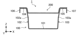
- FIG. 2 is a diagram showing a cross section perpendicular to the axial direction of the automobile structural member.
- the automobile structural member 1 (hereinafter sometimes simply referred to as “structural member 1") is used, for example, as a skeletal member of the vehicle body, and is particularly used in areas where bending deformation is likely to occur when a collision load is input. Specifically, it can be used as skeletal members such as bumper beams (front bumper beams or rear bumper beams), side sills, roof side rails, cross members (floor cross members, roof cross members, etc.), or center pillars.
- the X, Y, and Z directions are perpendicular to each other, and the Y direction is parallel to the axial direction of the automobile structural member 1.
- the X, Y, and Z directions correspond to the following directions.
- X direction vehicle length, Y direction: vehicle height, Z direction: vehicle width
- the structural member 1 comprises a first member 100 and a second member 200.
- the first member 100 has a first top plate 101, two first vertical walls 102, 103, two first flanges 104, 105, and two first upright portions 106, 107.
- the first member 100 is a member whose cross section perpendicular to the axial direction (Y direction) is hat-shaped. More specifically, in the cross section perpendicular to the axial direction of the first member 100, each of the two first vertical walls 102, 103 is located between the first top plate 101 and each of the two first flanges 104, 105, and each of the two first flanges 104, 105 is located between each of the two first vertical walls 102, 103 and each of the two first upright portions 106, 107. Each part of the first member 100 will be described in more detail below.
- the first top plate 101 is a plate-like portion extending in the longitudinal direction of the structural member 1.
- the extension direction of the first top plate 101 is the vehicle width direction when the structural member 1 is applied to a frame member such as a bumper beam or cross member, the vehicle length direction when the structural member 1 is applied to a frame member such as a side sill or roof side rail, and the vehicle height direction when the structural member 1 is applied to a frame member such as a center pillar.
- the width of the first top plate 101 (the length in the X direction in FIG. 2) can be changed as appropriate depending on the location of the structural member 1 in the vehicle body, but is set to, for example, 30 to 200 mm.
- the two first vertical walls 102, 103 are arranged opposite each other.
- the ends of each of the two first vertical walls 102, 103 are connected to the first top plate 101, and ridges 108, 109 are formed between the two first vertical walls 102, 103 and the first top plate 101, respectively.
- These ridges 108, 109 extend in the axial direction (Y direction) of the structural member 1.
- the first vertical walls 102, 103 may be formed perpendicular to the first top plate 101 or may be formed at an angle.
- the angle between each of the two first vertical walls 102, 103 and the first top plate 101 is set to, for example, 90 to 110 degrees.
- the first flanges 104, 105 are connected to the ends of the first vertical walls 102, 103 opposite the connecting end of the first top plate 101, and protrude outward from each of the two first vertical walls 102, 103.
- a ridge portion 110 is formed between one of the two first flanges 104 and one of the two first vertical walls 102, and a ridge portion 111 is formed between the other first flange 105 and the other first vertical wall 103.
- These ridge portions 110, 111 extend in the axial direction (Y direction) of the structural member 1.
- the "height H of the first top plate” which is the height from the first flanges 104, 105 to the first top plate 101 will be described.
- a direction perpendicular to the straight line connecting the ridge line portion 108 and the ridge line portion 109 is defined as a direction Hv .
- the height H of the first top plate 101 is the length from the ridge line portions 110, 111 to the ridge line portions 108, 109 in the direction Hv .
- the direction Hv in the example shown in FIG. 2 is the same as the Z direction.
- the height H of the first top plate 101 is changed as appropriate depending on the application location of the structural member 1 in the vehicle body, but is set to, for example, 30 to 200 mm.
- the hat-shaped first member 100 may have an asymmetric shape, for example, as shown in Fig. 3.
- the length from one of the two first flanges 104 to the first top plate 101 is different from the length from the other first flange 105 to the first top plate 101.
- the longer of the length H1 from the ridge line portion 110 to the ridge line portion 108 in the direction Hv and the length H2 from the ridge line portion 111 to the ridge line portion 109 in the direction Hv is defined as the height H of the first top plate 101.
- the length H1 is longer than the length H2 , so the length H1 is the height H of the first top plate 101.
- the first upright portions 106, 107 protrude from the tip ends of the first flanges 104, 105 (the ends of the first flanges 104, 105 opposite the connection side with the first vertical walls 102, 103) toward the first top plate 101.
- a ridge portion 112 is formed between one of the two first upright portions 106 and one of the two first flanges 104, and a ridge portion 113 is formed between the other first upright portion 107 and the other first flange 105.
- These ridge portions 112, 113 extend in the axial direction (Y direction) of the structural member 1.
- the length from the first flanges 104, 105 to the tip of the first upright portions 106, 107 in the direction perpendicular to the first top plate 101 (Z direction) is defined as the height of the first upright portions 106, 107.
- the height of the first uprights 106, 107 can be changed as appropriate depending on the location of the structural member 1 on the vehicle body and the required load-bearing performance, but is set to, for example, 0.15 to 0.50 times the height H of the first top plate 101.
- the second member 200 is a member whose cross section perpendicular to the axial direction (Y direction) is hat-shaped. More specifically, in the cross section perpendicular to the axial direction of the second member 200, each of the two second vertical walls 202, 203 is located between the second top plate 201 and each of the two second flanges 204, 205. Each part of the second member 200 will be described in more detail below.
- the second top plate 201 is a plate-shaped portion that faces the first top plate 101 and extends along the extension direction of the first top plate 101.
- the second top plate 201 is also located between the two first vertical walls 102, 103 of the first member 100 described above.
- the hat-shaped second member 200 may have an asymmetric shape, for example, as shown in Fig. 3.
- the length from one of the two second flanges 204 to the second top plate 201 is different from the length from the other second flange 205 to the second top plate 201.
- the longer of the length h1 from the ridge line portion 208 to the ridge line portion 206 in the direction hv and the length h2 from the ridge line portion 209 to the ridge line portion 207 in the direction hv is set as the height h of the second top plate 201.
- the length h1 is longer than the length h2 , so the length h1 is the height h of the second top plate 201.
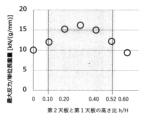
- the ratio (h/H) of the height h of the second top plate 201 to the height H of the first top plate 101 is preferably 0.10 to 0.52.
- the height ratio (h/H) is more preferably 0.15 or more, and even more preferably 0.20 or more.
- the height ratio (h/H) is more preferably 0.48 or less, and even more preferably 0.45 or less.
- the two second vertical walls 202, 203 are arranged opposite each other.
- the ends of each of the two second vertical walls 202, 203 are connected to the second top plate 201, and ridges 206, 207 are formed between the two second vertical walls 202, 203 and the second top plate 201, respectively.
- These ridges 206, 207 extend in the axial direction (Y direction) of the structural member 1.
- the second top plate 201 is positioned between the two first vertical walls 102, 103 of the first member 100, and thus each of the two second vertical walls 202, 203 is disposed in a position facing each of the two first vertical walls 102, 103.
- one of the two second vertical walls 202 faces one of the two first vertical walls 102
- the other second vertical wall 203 faces the other first vertical wall 103.
- the second vertical walls 202, 203 need to be located in the vicinity of the first vertical walls 102, 103 so that the second vertical walls 202, 203 come into contact with the first vertical walls 102, 103 deformed by the collision load.
- the distance between the second vertical walls 202, 203 and the first vertical walls 102, 103 needs to be 5.0 mm or less, that is, the gap formed between the second vertical walls 202, 203 and the first vertical walls 102, 103 needs to be 5.0 mm or less.
- the above gap is more preferably equal to or less than the plate thickness of the first vertical walls 102, 103, and even more preferably 0 mm. In other words, it is preferable that the second vertical walls 202, 203 are in contact with the first vertical walls 102, 103.
- one of the two second vertical walls 202 is parallel to one of the two first vertical walls 102, and it is preferable that the other second vertical wall 203 is parallel to the other first vertical wall 103.
- the second flanges 204, 205 are connected to the ends of the second vertical walls 202, 203 opposite the connecting end of the second top plate 201, and protrude outward from each of the second vertical walls 202, 203.
- a ridge portion 208 is formed between one of the two second flanges 204 and one of the two second vertical walls 202, and a ridge portion 209 is formed between the other second flange 205 and the other second vertical wall 203. These ridge portions 208, 209 extend in the axial direction (Y direction) of the structural member 1.
- Each of the first member 100 and the second member 200 described above is manufactured by, for example, press-forming a flat plate made of a metal material.
- the metal material is, for example, a steel material, an aluminum alloy member, a magnesium alloy member, or the like.
- the effect of improving the weight efficiency of the load-bearing performance can be enhanced by using a steel material with a tensile strength of 690 MPa or more.
- the tensile strength is preferably 780 MPa or more, and more preferably 980 MPa or more or 1180 MPa or more.
- the material of the first member 100 and the material of the second member 200 may be different from each other.
- the total length (length in the axial direction) of the first member 100 and the total length of the second member 200 are changed as appropriate depending on the application location of the structural member 1 in the vehicle body, and are, for example, 1000 to 3000 mm. Note that the total length of the first member 100 and the total length of the second member 200 may be different from each other.
- the plate thickness of the first member 100 and the plate thickness of the second member 200 are changed as appropriate depending on the application location of the structural member 1 in the vehicle body and the required load-bearing performance, and are, for example, 0.5 to 6.0 mm.
- the plate thickness of the first member 100 and the second member 200 may be, for example, 0.8 mm or more, or 1.0 mm or more.
- the plate thickness of the first member 100 and the second member 200 may be, for example, 4.0 mm or less, or 3.0 mm or less.
- the plate thickness of the first member 100 and the second member 200 may be different from each other.
- first member 100 and the second member 200 have been described above. These first member 100 and second member 200 are joined at the joint 300.
- each of the two first flanges 104, 105 and each of the two second flanges 204, 205 are overlapped, and the flanges are joined by a known joining means.
- the joining means is not particularly limited, but may be, for example, a welding means such as spot welding, laser welding, or plasma welding, or an adhesive means using an industrial adhesive.
- a hollow portion 301 extending along the axial direction (Y direction) is formed in the structural member 1, and the cross section perpendicular to the axial direction becomes a closed cross section.
- the second member 200 acts like a closing plate to make the hat-shaped first member 100 into a closed cross section.
- the schematic configuration of the structural member 1 according to this embodiment is as described above. Next, the deformation behavior of the structural member 1 during a collision will be described.
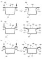
- FIG. 4 is a diagram for explaining the deformation behavior of structural members.
- FIG. 4 also illustrates the deformation behavior of other structural members.
- the left side of FIG. 4 shows the state of each structural member before deformation, and the right side shows the state after deformation.
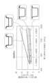
- Figure 5 is a load-stroke diagram to explain the change over time in the reaction force generated in each structural member shown in Figure 4.
- This diagram is a schematic representation of the predicted load-stroke diagram for each structural member when a collision simulation is performed, and shows the relationship between the impactor's stroke amount (amount of displacement) and the load (i.e., the reaction force generated on the structural member side).
- the structural member 800 shown in FIG. 4(A) has a configuration in which a hat-shaped member 810 and a closing plate 820 are joined together.
- this structural member 800 after a collision load is input, excessive out-of-plane deformation is likely to occur first in the areas of the vertical walls 811 and 812 of the hat-shaped member 810 near the flanges 813 and 814.
- the structural member 900 shown in FIG. 4(B) has a configuration in which a hat-shaped member 910 and the second member 200 in this embodiment are joined together.
- the hat-shaped member 910 is a member in which the first standing portions 106, 107 are not formed compared to the first member 100 in this embodiment.
- the structural member 900 When a collision load is input to the structural member 900, the second vertical walls 202, 203 of the second member 200 collapse outward, and the second top plate 201, the second vertical walls 202, 203, and the second flanges 204, 205 are deformed into a single flat plate. In the process of flattening the hat-shaped second member 200 in this manner, a deformation resistance force against the collision load is generated. Therefore, although out-of-plane deformation occurs in the vertical walls 911, 912 of the hat-shaped member 910 in the structural member 900 as well, the maximum input load to the structural member 900 is greater than that of the structural member 800, as shown in FIG. 5, due to the deformation resistance force generated by the flattening of the second member 200. In other words, the structural member 900 has a superior load-bearing performance to the structural member 800.
- Figure 4 (C) shows the structural member 1 in this embodiment.
- a collision load is input to the structural member 1, similar to the structural member 900 shown in Figure 4 (B)
- a deformation resistance force is generated in the process of flattening the hat-shaped second member 200.
- the first upright portions 106, 107 of the first member 100 deform so as to open outward, and a deformation resistance force is also generated in this deformation process.
- both the deformation resistance force generated by the first upright portions 106, 107 of the first member 100 and the deformation resistance force generated by the hat-shaped second member 200 act, and the simultaneous generation of these deformation resistance forces creates a synergistic effect, making it difficult for excessive out-of-plane deformation of the first vertical walls 102, 103 to occur.
- the second vertical walls 202, 203 are located near the first vertical walls 102, 103, the second vertical walls 202, 203 come into contact with the first vertical walls 102, 103 when a collision load is input, thereby suppressing out-of-plane deformation of the first vertical walls 102, 103.
- the structural member 1 allows the structural member 1 to withstand a larger collision load, and as shown in FIG. 5, the maximum input load to the structural member 1 (in other words, the maximum reaction force generated in the structural member 1) is greater than that of the structural member 900. In other words, the structural member 1 has better load-bearing performance than the structural member 900.
- structural member 1 is superior to other structural members 800 and 900 in terms of weight efficiency of load-bearing performance.
- the maximum input load of the structural member 1 is greater than that of the other structural members 800 and 900, so that even after the input load has attenuated, the input load remains higher than the attenuated input load of the other structural members 800 and 900.
- the amount of collision energy absorbed by the structural member 1 is greater than that of the other structural members 800 and 900.
- the structural member 1 according to this embodiment is excellent not only in weight efficiency of load-bearing performance, but also in energy absorption performance.
- the above describes the automobile structural member 1 according to this embodiment.
- examples of the shape of the first member 100 will be described with reference to Figures 6 to 8, and examples of the shape of the second member 200 will be described with reference to Figures 9 and 10.
- the structural member 1 may be configured by any combination of the shapes of the first member 100 and the shapes of the second member 200 exemplified below.
- each of the two first vertical walls 102, 103 is provided with inflection sections 102a, 103a where the inclination angle changes slightly.
- the deformation behavior similar to that of Figure 4 (C) occurs when a collision load is input due to the synergistic effect of the deformation resistance force generated by the first upright sections 106, 107 and the deformation resistance force generated by the hat-shaped second member 200. This results in a structural member 1 with excellent weight efficiency in load-bearing performance.
- the second member 200 has two second standing portions 210, 211 protruding from each of the two second flanges 204, 205 toward the second top plate 201.
- the second standing portions 210, 211 increase the moment of inertia, so that the deformation resistance increases when a collision load is input, improving the load-bearing performance. Note that the effect of increasing the deformation resistance can be obtained by providing at least one second standing portion 210, 211.
- the gap between the second standing portions 210, 211 and the first standing portions 106, 107 is 5.0 mm or less, and it is more preferable that the second standing portions 210, 211 are in contact with the first standing portions 106, 107, and it is even more preferable that they are joined.
- the second member 200 is provided with a second groove portion 212 that is recessed from the second top plate 201 toward the outside of the closed cross section of the structural member 1, i.e., toward the outside of the hollow portion 301.
- the second groove portion 212 also extends along the axial direction (Y direction) of the structural member 1, and it is preferable that the second groove portion 212 extends, for example, from one end of the second top plate 201 to the other end in the axial direction.
- the second groove portion 212 increases the deformation resistance and improves the load-bearing performance.
- the model of Example 1 corresponds to the structural member 1 having the hat-shaped first member 100 and hat-shaped second member 200 shown in FIG. 2.
- the first top plate of the first member 100 was supported by two support points 302 spaced 700 mm apart, as shown in FIG. 11.
- two impactors 303 spaced approximately 233 mm apart between the two support points 302, were brought into contact with the second member 200 side, and the impactors 303 were moved toward the first member 100 side at 1000 mm/s, to perform the simulation.
- Example 1 The analysis conditions for the model of Example 1 are as follows. ⁇ Software name: LS-Dyna ⁇ Version: R9.3.1 ⁇ Mesh size: 3mm Element type: Shell element developed by Belytschko-Wong-Chiang Friction coefficient: 0.12 ⁇ Total length of structural members: 900 mm ⁇ Width of structural member: 125mm Material of first member: Steel plate (plate thickness 1.6 mm, tensile strength 1470 MPa) ⁇ Width of first top plate: 70mm ⁇ Height of first top plate H: 48 mm Height of first standing part: 10 mm - Material of the second member: Steel plate (plate thickness 1.2 mm, tensile strength 590 to 1470 MPa) ⁇ Height of second top plate h: 20 mm ⁇ Spot welding pitch: 30 mm Gap formed between the second vertical wall and the first vertical wall: 0 mm
- the model of Comparative Example 1 shown in Figure 12 corresponds to the structural member 800 shown in Figure 4 (A) in which a hat-shaped member and a closing plate are joined.
- the model of Comparative Example 2 corresponds to the structural member 900 shown in Figure 4 (B) in which two hat-shaped members that do not have a first standing portion are joined.
- the model of Comparative Example 3 corresponds to a hat-shaped member that has a first standing portion and a closing plate joined.
- the simulation conditions for the models of Comparative Examples 1 to 3 are the same as those for Example 1, except for the shape of the structural members.
- the simulation was performed multiple times with the tensile strength of the second member or closing plate set to different values within the range of 590 MPa to 1470 MPa.
- the model of Example 1 has better weight efficiency of load-bearing performance than the models of Comparative Examples 1 to 3.
- the greater the tensile strength of the steel plate used as the material for the second member the greater the difference in the effect of weight efficiency of load-bearing performance between Example 1 and Comparative Examples 1 to 3, and the greater the improvement in weight efficiency.
- the weight efficiency of the load-bearing performance of an automobile structural member that combines (1) providing a first upright portion on the hat-shaped first member and (2) making the second member hat-shaped and bringing the vertical wall of the second member and the vertical wall of the first member close to each other increases significantly to an extent that cannot be predicted from the weight efficiency obtained with an automobile structural member having only the above characteristic (1) and the weight efficiency obtained with an automobile structural member having only the above characteristic (2).
- the material of the first member is set to a steel plate with a thickness of 1.6 mm and a tensile strength of 1470 MPa
- the material of the second member is set to a steel plate with a thickness of 1.2 mm and a tensile strength of 1470 MPa.
- the other simulation conditions are the same as those in the above-mentioned simulation (1).
- Automobile structural member 100 First member 101 First top plate 102, 103 First vertical wall 104, 105 First flange 106, 107 First upright portion 108-113 Ridge line portion 114 First groove portion 200 Second member 201 Second top plate 202, 203 Second vertical wall 204, 205 Second flange 206-209 Ridge line portion 210, 211 Second upright portion 212 Second groove portion 300 Joint portion 301 Hollow portion 302 Support point 303 Impactor 800 Automobile structural member (conventional structure) 810: hat-shaped member 820: closing plate 900: automobile structural member (reference structure) 910 Hat-shaped member H Height of first top plate h Height of second top plate
Landscapes
- Engineering & Computer Science (AREA)
- Mechanical Engineering (AREA)
- Chemical & Material Sciences (AREA)
- Combustion & Propulsion (AREA)
- Transportation (AREA)
- Body Structure For Vehicles (AREA)
Priority Applications (2)
| Application Number | Priority Date | Filing Date | Title |
|---|---|---|---|
| CN202480043473.1A CN121568859A (zh) | 2023-10-12 | 2024-09-09 | 汽车构造构件 |
| JP2025521518A JP7842371B2 (ja) | 2023-10-12 | 2024-09-09 | 自動車構造部材 |
Applications Claiming Priority (2)
| Application Number | Priority Date | Filing Date | Title |
|---|---|---|---|
| JP2023-177017 | 2023-10-12 | ||
| JP2023177017 | 2023-10-12 |
Publications (1)
| Publication Number | Publication Date |
|---|---|
| WO2025079378A1 true WO2025079378A1 (ja) | 2025-04-17 |
Family
ID=95395596
Family Applications (1)
| Application Number | Title | Priority Date | Filing Date |
|---|---|---|---|
| PCT/JP2024/032231 Pending WO2025079378A1 (ja) | 2023-10-12 | 2024-09-09 | 自動車構造部材 |
Country Status (3)
| Country | Link |
|---|---|
| JP (1) | JP7842371B2 (https=) |
| CN (1) | CN121568859A (https=) |
| WO (1) | WO2025079378A1 (https=) |
Citations (5)
| Publication number | Priority date | Publication date | Assignee | Title |
|---|---|---|---|---|
| JPH04297376A (ja) * | 1991-03-26 | 1992-10-21 | Nissan Motor Co Ltd | 車体骨格メンバ |
| JPH07125651A (ja) * | 1993-11-04 | 1995-05-16 | Nissan Motor Co Ltd | 強度部材 |
| WO2019035185A1 (ja) * | 2017-08-15 | 2019-02-21 | 新日鐵住金株式会社 | バンパービーム及び車両 |
| WO2020100886A1 (ja) * | 2018-11-14 | 2020-05-22 | 日本製鉄株式会社 | 骨格部材 |
| JP2020152257A (ja) * | 2019-03-20 | 2020-09-24 | 日本製鉄株式会社 | 車体部材 |
Family Cites Families (2)
| Publication number | Priority date | Publication date | Assignee | Title |
|---|---|---|---|---|
| US20040201255A1 (en) | 1998-10-19 | 2004-10-14 | Martin Jonsson | Lightweight beam |
| JP7252443B2 (ja) | 2019-03-13 | 2023-04-05 | 日本製鉄株式会社 | 車体部材、および、車体構造 |
-
2024
- 2024-09-09 CN CN202480043473.1A patent/CN121568859A/zh active Pending
- 2024-09-09 WO PCT/JP2024/032231 patent/WO2025079378A1/ja active Pending
- 2024-09-09 JP JP2025521518A patent/JP7842371B2/ja active Active
Patent Citations (5)
| Publication number | Priority date | Publication date | Assignee | Title |
|---|---|---|---|---|
| JPH04297376A (ja) * | 1991-03-26 | 1992-10-21 | Nissan Motor Co Ltd | 車体骨格メンバ |
| JPH07125651A (ja) * | 1993-11-04 | 1995-05-16 | Nissan Motor Co Ltd | 強度部材 |
| WO2019035185A1 (ja) * | 2017-08-15 | 2019-02-21 | 新日鐵住金株式会社 | バンパービーム及び車両 |
| WO2020100886A1 (ja) * | 2018-11-14 | 2020-05-22 | 日本製鉄株式会社 | 骨格部材 |
| JP2020152257A (ja) * | 2019-03-20 | 2020-09-24 | 日本製鉄株式会社 | 車体部材 |
Also Published As
| Publication number | Publication date |
|---|---|
| JP7842371B2 (ja) | 2026-04-08 |
| CN121568859A (zh) | 2026-02-24 |
| JPWO2025079378A1 (https=) | 2025-04-17 |
Similar Documents
| Publication | Publication Date | Title |
|---|---|---|
| JP5382140B2 (ja) | 車両用フード構造 | |
| CN101641231B (zh) | 强化侧面碰撞性能的汽车用门 | |
| CN102985297B (zh) | 车辆用发动机盖结构 | |
| CN108495777A (zh) | 车辆前部构造 | |
| JP7678309B2 (ja) | 車体下部構造 | |
| EP4253114B1 (en) | Automotive battery case and method for manufacturing same | |
| JPWO2020085381A1 (ja) | 自動車骨格部材および電気自動車 | |
| JP6733848B1 (ja) | 自動車構造部材 | |
| JP4648047B2 (ja) | 自動車パネル構造体 | |
| CN108556924A (zh) | 一种提高40%偏置碰安全性能的a柱结构 | |
| JP7024878B2 (ja) | 自動車構造部材 | |
| JP2006341687A (ja) | 車体骨格部材の衝突エネルギー吸収構造および衝突エネルギー吸収方法 | |
| JP2003252246A (ja) | 車体パネル | |
| WO2025079670A1 (ja) | 自動車骨格部材の接合構造 | |
| WO2025079378A1 (ja) | 自動車構造部材 | |
| JP6733849B1 (ja) | フロアトンネル | |
| JP2009126359A (ja) | 衝突安全性に優れた自動車サイドドア | |
| JP2022129444A (ja) | 衝撃吸収部材 | |
| JP4764035B2 (ja) | 自動車パネル構造体 | |
| JP4834353B2 (ja) | 車両用エネルギ吸収ビーム及び車両用ドア構造 | |
| JP7376797B2 (ja) | 自動車骨格部材および電気自動車 | |
| CN117841625A (zh) | 车门和车辆 | |
| WO2026029065A1 (ja) | 自動車骨格部材 | |
| JP6613712B2 (ja) | 自動車車体の構造部材、その製造方法および自動車車体、ならびに衝撃エネルギー吸収方法 | |
| JP6766978B1 (ja) | 自動車構造部材 |
Legal Events
| Date | Code | Title | Description |
|---|---|---|---|
| ENP | Entry into the national phase |
Ref document number: 2025521518 Country of ref document: JP Kind code of ref document: A |
|
| WWE | Wipo information: entry into national phase |
Ref document number: 2025521518 Country of ref document: JP |
|
| 121 | Ep: the epo has been informed by wipo that ep was designated in this application |
Ref document number: 24876977 Country of ref document: EP Kind code of ref document: A1 |
|
| WWE | Wipo information: entry into national phase |
Ref document number: 202617004411 Country of ref document: IN |
|
| WWE | Wipo information: entry into national phase |
Ref document number: 2601000977 Country of ref document: TH |
|
| WWP | Wipo information: published in national office |
Ref document number: 202617004411 Country of ref document: IN |