WO2025057681A1 - 不飽和カルボン酸製造用触媒および不飽和カルボン酸の製造方法 - Google Patents
不飽和カルボン酸製造用触媒および不飽和カルボン酸の製造方法 Download PDFInfo
- Publication number
- WO2025057681A1 WO2025057681A1 PCT/JP2024/029661 JP2024029661W WO2025057681A1 WO 2025057681 A1 WO2025057681 A1 WO 2025057681A1 JP 2024029661 W JP2024029661 W JP 2024029661W WO 2025057681 A1 WO2025057681 A1 WO 2025057681A1
- Authority
- WO
- WIPO (PCT)
- Prior art keywords
- catalyst
- unsaturated carboxylic
- producing
- carboxylic acid
- width
- Prior art date
- Legal status (The legal status is an assumption and is not a legal conclusion. Google has not performed a legal analysis and makes no representation as to the accuracy of the status listed.)
- Pending
Links
Images
Classifications
-
- B—PERFORMING OPERATIONS; TRANSPORTING
- B01—PHYSICAL OR CHEMICAL PROCESSES OR APPARATUS IN GENERAL
- B01J—CHEMICAL OR PHYSICAL PROCESSES, e.g. CATALYSIS OR COLLOID CHEMISTRY; THEIR RELEVANT APPARATUS
- B01J23/00—Catalysts comprising metals or metal oxides or hydroxides, not provided for in group B01J21/00
- B01J23/70—Catalysts comprising metals or metal oxides or hydroxides, not provided for in group B01J21/00 of the iron group metals or copper
- B01J23/76—Catalysts comprising metals or metal oxides or hydroxides, not provided for in group B01J21/00 of the iron group metals or copper combined with metals, oxides or hydroxides provided for in groups B01J23/02 - B01J23/36
- B01J23/84—Catalysts comprising metals or metal oxides or hydroxides, not provided for in group B01J21/00 of the iron group metals or copper combined with metals, oxides or hydroxides provided for in groups B01J23/02 - B01J23/36 with arsenic, antimony, bismuth, vanadium, niobium, tantalum, polonium, chromium, molybdenum, tungsten, manganese, technetium or rhenium
- B01J23/85—Chromium, molybdenum or tungsten
- B01J23/888—Tungsten
-
- C—CHEMISTRY; METALLURGY
- C07—ORGANIC CHEMISTRY
- C07B—GENERAL METHODS OF ORGANIC CHEMISTRY; APPARATUS THEREFOR
- C07B61/00—Other general methods
-
- C—CHEMISTRY; METALLURGY
- C07—ORGANIC CHEMISTRY
- C07C—ACYCLIC OR CARBOCYCLIC COMPOUNDS
- C07C51/00—Preparation of carboxylic acids or their salts, halides or anhydrides
- C07C51/16—Preparation of carboxylic acids or their salts, halides or anhydrides by oxidation
- C07C51/21—Preparation of carboxylic acids or their salts, halides or anhydrides by oxidation with molecular oxygen
- C07C51/23—Preparation of carboxylic acids or their salts, halides or anhydrides by oxidation with molecular oxygen of oxygen-containing groups to carboxyl groups
- C07C51/235—Preparation of carboxylic acids or their salts, halides or anhydrides by oxidation with molecular oxygen of oxygen-containing groups to carboxyl groups of —CHO groups or primary alcohol groups
-
- C—CHEMISTRY; METALLURGY
- C07—ORGANIC CHEMISTRY
- C07C—ACYCLIC OR CARBOCYCLIC COMPOUNDS
- C07C57/00—Unsaturated compounds having carboxyl groups bound to acyclic carbon atoms
- C07C57/02—Unsaturated compounds having carboxyl groups bound to acyclic carbon atoms with only carbon-to-carbon double bonds as unsaturation
- C07C57/03—Monocarboxylic acids
- C07C57/04—Acrylic acid; Methacrylic acid
Definitions
- the present invention relates to a catalyst for producing unsaturated carboxylic acids in high yields by gas-phase catalytic oxidation of unsaturated aldehydes in the presence of molecular oxygen or a molecular oxygen-containing gas, a method for producing the catalyst, and a method for producing unsaturated carboxylic acids using the catalyst.
- Acrylic acid is becoming increasingly important as a raw material for absorbent resins, adhesives, etc. For this reason, in recent years there has been a demand for improved catalyst performance for producing acrylic acid through a gas-phase catalytic oxidation reaction using acrolein as a raw material. As a result, various companies have been making various improvements to catalysts that can produce acrylic acid stably over the long term with high yields, and the following proposals have been made, for example:
- Patent documents 1 to 4 disclose improvements in catalyst composition, etc., focusing on the X-ray diffraction peaks of catalytically active components. These catalysts are proposed as catalysts that achieve high activity and high yield. Patent documents 5 and 6 also provide improvement guidelines aimed at improving mechanical strength, and improve catalyst performance by preventing powdering during filling. Patent document 7 aims to improve the long-term stability of catalytic reactions by setting the standard deviation of catalyst particle size within a specific range. Patent document 8 proposes a method for producing a catalyst that combines high catalytic performance and mechanical strength by controlling the relative centrifugal acceleration when molding using a rolling granulator.
- Patent document 9 proposes a method for producing a high-yield catalyst by controlling the density of the catalyst molded body and the roughness of the catalyst surface.
- Patent document 10 proposes a manufacturing method for obtaining high activity and selectivity by controlling the crystal size within a specific range in nanocrystalline molybdenum mixed oxide.
- the objective of the present invention is to improve the catalytic activity of a catalyst that uses an unsaturated aldehyde as a raw material to produce an unsaturated carboxylic acid through a gas-phase catalytic oxidation reaction.
- a catalyst for producing an unsaturated carboxylic acid comprising a catalytically active component having a composition represented by the following formula (1), and an X-ray diffraction pattern obtained using CuK ⁇ radiation as an X-ray source having a half-width of a peak at 22.2° ⁇ 0.3° of 0.65° or more and 1.60° or less:
- Mo Mo, V, W, Cu, Sb, and O represent molybdenum, vanadium, tungsten, copper, antimony, and oxygen, respectively;
- X represents at least one element selected from the group consisting of alkali metals and thallium;
- Y represents at least one element selected from the group consisting of magnesium, calcium, strontium, barium, and zinc;
- Z represents niobium
- Each of the elements represents at least one element selected from the group consisting of marium, germanium, titanium, and arsenic.
- a, b, c, d, e, f, g, and h represent the atomic ratio of each element, and are 0 ⁇ a ⁇ 10.0, 0 ⁇ b ⁇ 10.0, 0 ⁇ c ⁇ 6.0, 0 ⁇ d ⁇ 10.0, 0 ⁇ e ⁇ 0.50, 0 ⁇ f ⁇ 1.0, and 0 ⁇ g ⁇ 6.0 relative to 12 molybdenum atoms.
- h represents the number of oxygen atoms required to satisfy the valence of each of the components.
- Catalyst for producing an unsaturated carboxylic acid according to the above 1) wherein in the above formula (1), 1.0 ⁇ a ⁇ 5.0, 0.50 ⁇ b ⁇ 3.0, 0.50 ⁇ c ⁇ 3.0 and 0 ⁇ d ⁇ 2.0.
- the catalyst for producing an unsaturated carboxylic acid according to the above 1) or 2) which is a catalyst in which a catalytically active component is supported on an inert carrier.
- a method for producing an unsaturated carboxylic acid comprising using a reaction tube packed in multiple layers with two or more kinds of the catalyst for producing an unsaturated carboxylic acid according to any one of 1) to 4) above.
- high catalytic activity can be maintained when producing an unsaturated carboxylic acid, i.e., (meth)acrylic acid, by subjecting an unsaturated aldehyde, preferably (meth)acrolein, as a raw material to a gas-phase catalytic oxidation reaction.
- unsaturated carboxylic acid i.e., (meth)acrylic acid
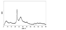
- FIG. 2 is a diagram showing an XRD chart of the catalytically active component of the catalyst 1 produced in Example 1.
- the catalyst of the present invention has an X-ray diffraction (XRD) pattern obtained using CuK ⁇ radiation as an X-ray source, in which the half-width of the peak at 22.2° ⁇ 0.3° is 0.65° or more and 1.60° or less.
- XRD X-ray diffraction
- the half width means the full width at half maximum, that is, the width at a portion where the intensity is 1/2 of the peak value as a quadratic function after fitting described later.
- the oxidation reaction of (meth)acrolein is believed to proceed inside the crystal structure, and the more the crystals grow, the more reaction sites there are inside the crystal structure, which is believed to improve the activity of the catalyst.
- the crystals become too large, physical resistance occurs, making it difficult for the raw material (meth)acrolein to pass through the inside of the crystal structure, which is believed to reduce the activity.
- the half-width of the peak at 22.2° ⁇ 0.3° also increases or decreases depending on the number of crystals. When the proportion of amorphous parts in the active ingredient decreases and the number of crystals increases, the diffraction plane increases, so the half-width decreases, and the activity improves because the active ingredient increases.
- the half-width of the peak at 22.2° ⁇ 0.3° is a value that also increases or decreases depending on the distortion of the crystal structure.
- catalytic reactions tend to proceed in areas with structural defects, and it is believed that catalysts for producing (meth)acrylic acid also have a high activity when there is a certain degree of structural defect.
- the crystal structure is distorted, and the half-width of the peak at 22.2° ⁇ 0.3° in the X-ray diffraction pattern becomes a large value.
- a catalyst in which the degree of crystal growth and structural distortion are within a certain range and the number of crystals is large is a preferable form for a catalyst for producing (meth)acrylic acid, and have found that this can be achieved by adjusting the half-width of the peak at 22.2° ⁇ 0.3° in the X-ray diffraction pattern to be 0.65° or more and 1.60° or less.
- the half-width in the present invention is 0.65° or more and 1.60° or less, but more preferred values as the lower limit are 0.70°, 0.75°, 0.80°, 0.85°, 0.88°, 0.90°, 0.92°, 0.94°, and 0.96°, respectively, with 0.98° being particularly preferred.
- preferred values as the upper limit are 1.55°, 1.50°, 1.47°, 1.45°, 1.40°, 1.35°, and 1.33°, respectively, with 1.31° being particularly preferred.
- the half width of the peak at 22.2° ⁇ 0.3° is preferably 0.70° or more and 1.60° or less, more preferably 0.75° or more and 1.60° or less, more preferably 0.80° or more and 1.60° or less, more preferably 0.85° or more and 1.55° or less, more preferably 0.88° or more and 1.50° or less, more preferably 0.90° or more and 1.47° or less, more preferably 0.92° or more and 1.45° or less, more preferably 0.94° or more and 1.40° or less, more preferably 0.96° or more and 1.35° or less, and most preferably 0.98° or more and 1.31° or less.
- the half-width of the peak at 22.2° ⁇ 0.3° may be 0.65° or more and 1.47° or less, 0.65° or more and 1.45° or less, 0.65° or more and 1.40° or less, 0.85° or more and 1.60° or less, 0.88° or more and 1.60° or less, or 0.90° or more and 1.60° or less.
- the catalyst of the present invention is more preferably one in which the half-width of the peak at 8.3° ⁇ 0.5° is greater than 0 and not greater than 2.82°.
- the upper limit of the half-width of the peak at 8.3° ⁇ 0.5° is more preferably 2.75°, 2.70°, 2.65°, 2.60°, 2.55°, 2.50°, 2.45°, 2.40°, and particularly preferably 2.37°.
- the lower limit is more preferably 1.00°, 1.50°, 2.00°, 2.10°, 2.20°, and particularly preferably 2.30°.
- the half-width of the peak at 8.3° ⁇ 0.5° is more preferably greater than 0 and not greater than 2.75°, more preferably greater than 0 and not greater than 2.70°, more preferably greater than 0 and not greater than 2.65°, more preferably 1.00° or more and not greater than 2.60°, more preferably 1.50° or more and not greater than 2.55°, more preferably 2.00° or more and not greater than 2.50°, more preferably 2.10° or more and not greater than 2.45°, more preferably 2.20° or more and not greater than 2.40°, and most preferably 2.30° or more and not greater than 2.37°.
- the catalyst of the present invention is more preferably one in which the half-width of the peak at 26.7° ⁇ 0.3° is 4.66° or more and 7.40° or less. More preferably, the upper limit of the half-width of the peak at 26.7° ⁇ 0.3° is 7.30°, 7.25°, 7.20°, 7.00°, 6.90°, 6.80°, 6.70°, 6.60°, 6.50°, 6.40°, 6.30°, 6.20°, 6.15°, or 6.10°, and particularly preferably 6.05°.
- the lower limit is more preferably 4.80°, 5.00°, 5.05°, 5.10°, 5.20°, 5.30°, 5.40°, 5.45°, 5.50°, 5.60°, 5.70°, 5.80°, or 5.90°, and is particularly preferably 5.95°.
- the half width of the peak at 26.7° ⁇ 0.3° is more preferably 4.66° or more and 7.30° or less, more preferably 4.66° or more and 7.25° or less, more preferably 4.80° or more and 7.20° or less, more preferably 5.00° or more and 7.00° or less, more preferably 5.10° or more and 6.90° or less, more preferably 5.20° or more and 6.80° or less, more preferably 5.30° or more and 6.70° or less, more preferably 5.40° or more and 6.60° or less, more preferably 5.45° or more and 6.50° or less, more preferably 5.50° or more and 6.40° or less, more preferably 5.60° or more and 6.30° or less, more preferably 5.70° or more and 6.20° or less, more preferably 5.80° or more and 6.15° or less, more preferably 5.90° or more and 6.10° or less, and most preferably 5.95° or more and 6.05° or less.
- the catalyst of the present invention is more preferably 0.64° or more and 1.03° or less in terms of the half-width of the peak at 45.4° ⁇ 0.3°. More preferably, the upper limit of the half-width of the peak at 45.4° ⁇ 0.3° is 1.00°, 0.99, 0.98°, and particularly preferably 0.97°. Similarly, the lower limit is more preferably 0.65°, 0.67°, 0.70°, 0.75°, 0.80°, 0.85°, 0.90°, and particularly preferably 0.95°.
- the half width of the peak at 45.4° ⁇ 0.3° is more preferably 0.65° or more and 1.03° or less, more preferably 0.67° or more and 1.03° or less, more preferably 0.70° or more and 1.03° or less, more preferably 0.75° or more and 1.03° or less, more preferably 0.80° or more and 1.00° or less, more preferably 0.85° or more and 0.99° or less, more preferably 0.90° or more and 0.98° or less, and most preferably 0.95° or more and 0.97° or less.
- the catalyst of the present invention has a composition represented by the following formula (1).
- Mo, V, W, Cu, Sb, and O represent molybdenum, vanadium, tungsten, copper, antimony, and oxygen, respectively;
- X represents at least one element selected from the group consisting of alkali metals and thallium;
- Y represents at least one element selected from the group consisting of magnesium, calcium, strontium, barium, and zinc;
- Z represents bismuth, tellurium, silver, selenium, silicon, aluminum, boron, niobium, cerium, tin, chromium, manganese, iron, cobalt, nickel, samarium, germanium, and arsenic.
- Each of the elements represents at least one element selected from
- a, b, c, d, e, f, g, and h represent the atomic ratio of each element, and are 0 ⁇ a ⁇ 10.0, 0 ⁇ b ⁇ 10.0, 0 ⁇ c ⁇ 6.0, 0 ⁇ d ⁇ 10.0, 0 ⁇ e ⁇ 0.50, 0 ⁇ f ⁇ 1.0, and 0 ⁇ g ⁇ 6.0 relative to 12 molybdenum atoms.
- h represents the number of oxygen atoms required to satisfy the valence of each of the components.
- the preferred ranges of a to g are as follows:
- the lower limit of a is, in order of desirability, 0.20, 0.50, 0.80, 1.0, 1.5, 2.0, 2.2, and 2.4, and is most desirably 2.6
- the upper limit of a is, in order of desirability, 9.0, 8.0, 7.0, 6.0, 5.0, 4.5, 4.0, 3.5, 3.3, and 3.1, and is most desirably 2.9.
- the range of a is preferably 0.20 ⁇ a ⁇ 9.0, more preferably 0.20 ⁇ a ⁇ 8.0, more preferably 0.20 ⁇ a ⁇ 7.0, more preferably 0.50 ⁇ a ⁇ 6.0, more preferably 0.80 ⁇ a ⁇ 5.0, more preferably 1.0 ⁇ a ⁇ 4.5, more preferably 1.5 ⁇ a ⁇ 4.0, more preferably 2.0 ⁇ a ⁇ 3.5, more preferably 2.2 ⁇ a ⁇ 3.3, more preferably 2.4 ⁇ a ⁇ 3.1, and most preferably 2.6 ⁇ a ⁇ 2.9.
- the lower limit of b is, in order of desirability, 0.10, 0.20, 0.30, 0.40, 0.50, and 0.60, and is most desirably 0.70
- the upper limit of b is, in order of desirability, 9.0, 8.0, 7.0, 6.0, 5.0, 4.0, 3.0, 2.5, 2.0, 1.5, and 1.3, and is most desirably 1.1.
- the range of b is preferably 0.10 ⁇ b ⁇ 9.0, more preferably 0.10 ⁇ b ⁇ 8.0, more preferably 0.10 ⁇ b ⁇ 7.0, more preferably 0.10 ⁇ b ⁇ 6.0, more preferably 0.10 ⁇ b ⁇ 5.0, more preferably 0.10 ⁇ b ⁇ 4.0, more preferably 0.20 ⁇ b ⁇ 3.0, more preferably 0.30 ⁇ b ⁇ 2.5, more preferably 0.40 ⁇ b ⁇ 2.0, more preferably 0.50 ⁇ b ⁇ 1.5, more preferably 0.60 ⁇ b ⁇ 1.3, and most preferably 0.70 ⁇ b ⁇ 1.1.
- the lower limit of c is, in order of desirability, 0.10, 0.20, 0.30, 0.40, 0.50, 0.60, 0.70, 0.80, 0.90, and 1.0, and is most desirably 1.3
- the upper limit of c is, in order of desirability, 5.0, 4.0, 3.0, 2.5, 2.0, and 1.8, and is most desirably 1.6.
- the range of c is preferably 0.10 ⁇ c ⁇ 5.0, more preferably 0.20 ⁇ c ⁇ 5.0, more preferably 0.30 ⁇ c ⁇ 5.0, more preferably 0.40 ⁇ c ⁇ 5.0, more preferably 0.50 ⁇ c ⁇ 5.0, more preferably 0.60 ⁇ c ⁇ 4.0, more preferably 0.70 ⁇ c ⁇ 3.0, more preferably 0.80 ⁇ c ⁇ 2.5, more preferably 0.90 ⁇ c ⁇ 2.0, more preferably 1.0 ⁇ c ⁇ 1.8, and most preferably 1.3 ⁇ c ⁇ 1.6.
- the lower limit of d is, in order of desirability, 0.11, 0.15, 0.18, 0.20, 0.25, 0.30, and 0.35, and is most desirably 0.40
- the upper limit of d is, in order of desirability, 9.0, 8.0, 7.0, 6.0, 5.0, 4.0, 3.0, 2.5, 2.0, 1.5, and 1.0, and is most desirably 0.70.
- the range of d is preferably 0.11 ⁇ d ⁇ 9.0, more preferably 0.11 ⁇ d ⁇ 8.0, more preferably 0.11 ⁇ d ⁇ 7.0, more preferably 0.11 ⁇ d ⁇ 6.0, more preferably 0.11 ⁇ d ⁇ 5.0, more preferably 0.15 ⁇ d ⁇ 4.0, more preferably 0.18 ⁇ d ⁇ 3.0, more preferably 0.20 ⁇ d ⁇ 2.5, more preferably 0.25 ⁇ d ⁇ 2.0, more preferably 0.30 ⁇ d ⁇ 1.5, more preferably 0.35 ⁇ d ⁇ 1.0, and most preferably 0.40 ⁇ d ⁇ 0.70.
- the upper limit of e is, in order of desirability, 0.40, 0.30, 0.20, and 0.10.
- the range of e is, in order of desirability, 0 ⁇ e ⁇ 0.40, 0 ⁇ e ⁇ 0.30, and 0 ⁇ e ⁇ 0.20, and the most preferable range is 0 ⁇ e ⁇ 0.10.
- the upper limit of f is, in order of preference, 0.80, 0.50, 0.20, and 0.15, and is most preferably 0.10. That is, the range of f is, in order of preference, 0 ⁇ f ⁇ 0.80, 0 ⁇ f ⁇ 0.50, 0 ⁇ f ⁇ 0.20, and 0 ⁇ f ⁇ 0.15, and the most preferable range is 0 ⁇ f ⁇ 0.10.
- the upper limit of g is, in order of desirability, 5.0, 4.0, 3.0, 2.0, and 1.0.
- the range of g is, in order of desirability, 0 ⁇ g ⁇ 5.0, 0 ⁇ g ⁇ 4.0, 0 ⁇ g ⁇ 3.0, and 0 ⁇ g ⁇ 2.0, and the most preferable range is 0 ⁇ g ⁇ 1.0.
- e, f and g are 0.
- the catalyst of the present invention When the catalyst of the present invention is used in a reaction for producing a corresponding unsaturated carboxylic acid from an unsaturated aldehyde such as acrolein or methacrolein as a raw material, particularly in a reaction for producing acrylic acid by gas-phase catalytic oxidation of acrolein with molecular oxygen or a molecular oxygen-containing gas, it is very effective in improving catalytic activity and reducing the differential pressure compared to known methods. In addition, in a process of partial oxidation reaction accompanied by heat generation, it is expected to improve stability by reducing hot spot temperature, etc.
- the catalyst of the present invention is also effective in reducing by-products that adversely affect the environment and the quality of the final product, such as carbon monoxide (CO), carbon dioxide (CO 2 ), acetaldehyde, acetic acid, and formaldehyde.
- CO carbon monoxide
- CO 2 carbon dioxide
- acetaldehyde acetaldehyde
- acetic acid formaldehyde
- Step a) Preparation Examples of raw materials for the elements constituting the catalyst include those shown below.
- ammonium molybdate is used as the molybdenum component raw material, a high performance catalyst is obtained.
- the raw materials of tungsten, vanadium, antimony, copper and other elements oxides or ammonium salts, carbonates, sulfates, organic acid salts, hydroxides, metal powders, etc. that can be turned into oxides by ignition, or mixtures thereof, can be used.
- the preferred raw materials differ depending on the type of element, and the half-width of the peak at 22.2° ⁇ 0.3° in the XRD pattern can also be adjusted accordingly.
- ammonium salts are preferred for tungsten and vanadium, and sulfates are preferred for copper.
- antimony raw materials compounds in which the valence of antimony is trivalent are preferred, and acetic acid, carbonic acid, tartaric acid, oxalic acid, and other carboxylic acid salts are particularly preferred.
- the vanadium raw material, molybdenum raw material, tungsten raw material, and antimony raw material are mixed in a desired ratio in an aqueous solvent at 20 to 95° C., heated and stirred for about 1 hour, and then X component raw material, Y component raw material, and Z component raw material are added as necessary, and finally an aqueous solution in which the copper raw material is dissolved is added.
- An aqueous solution or slurry containing the catalyst components is obtained, which will be referred to as the prepared liquid (A) hereinafter.
- the preparation liquid (A) does not necessarily contain all the catalyst constituent elements, and some elements or some amounts of them may be added in a subsequent step.
- the preparation liquid (A) when preparing the preparation liquid (A), if the amount of water in which each component raw material is dissolved or an acid such as sulfuric acid, nitric acid, hydrochloric acid, tartaric acid, or acetic acid is added for dissolution, the acid concentration in the aqueous solution sufficient to dissolve the raw materials is not appropriate, for example, within the range of 5% by mass to 99% by mass, the preparation liquid (A) may take the form of a clay-like mass, which will not be an excellent catalyst. Therefore, it is preferable that the preparation liquid (A) obtained is in the form of an aqueous solution or a slurry, in order to obtain an excellent catalyst.
- an acid such as sulfuric acid, nitric acid, hydrochloric acid, tartaric acid, or acetic acid
- the drying method is not particularly limited as long as it can completely dry the preparation (A), and examples thereof include drum drying, freeze drying, spray drying, and evaporation to dryness.
- spray drying is particularly preferred, which can dry the slurry into powder or granules in a short time.
- the drying temperature of the spray drying varies depending on the concentration of the slurry, the liquid delivery speed, etc., but is generally 70 to 150°C at the outlet of the dryer. It is also preferable to dry the mixture so that the average particle size of the dry powder obtained at this time is 20 to 700 ⁇ m. In this way, a dry powder (B) is obtained.
- Step c) Pre-calcination The obtained dry powder (B) is calcined under air flow at 200°C to 500°C, preferably 300°C to 400°C, which tends to improve the moldability, mechanical strength, and catalytic performance of the catalyst.
- the calcination time is preferably 1 hour to 12 hours. In this way, a pre-calcined body (C) is obtained.
- the obtained pre-fired body (C) is obtained as a solid (D) in which the dry powder (B) is aggregated by pre-firing.
- the solid (D) is pulverized.
- the pulverization method is not particularly limited, and examples thereof include a roller mill, a jet mill, a hammer mill, a ball mill, and a vibration mill.
- the average particle size (pre-fired median size) of the pre-fired powder (E) obtained at this time is preferably 50 ⁇ m or less, more preferably 40 ⁇ m or less, even more preferably 30 ⁇ m or less, and particularly preferably 25 ⁇ m or less.
- the crushed pre-calcined powder (E) is described as a catalyst precursor.
- the pre-calcined body (C) may be used as a catalyst precursor.
- Step e) Molding There is no particular limitation on the molding method, but when molding into a cylindrical or ring shape, a method using a tablet molding machine, an extrusion molding machine, etc. is preferred. More preferably, when molding into a spherical shape, the pre-sintered powder (E) may be molded into a spherical shape using a molding machine, but a method in which the pre-sintered powder (E) (containing a molding aid and a strength improver, if necessary) is supported on a carrier such as an inactive ceramic is preferred.
- the supporting method is widely known to be a rolling granulation method, a method using a centrifugal fluidized coating device, a wash coat method, etc., and is not particularly limited as long as it can uniformly support the pre-calcined powder (E) on the carrier, but considering the production efficiency of the catalyst and the performance of the prepared catalyst, it is more preferable to use a device having a flat or uneven disk at the bottom of a fixed cylindrical container, rotate the disk at high speed, and vigorously stir the carrier charged in the container by the rotation and revolution of the carrier itself, and add the pre-calcined powder (E) and, if necessary, a molding aid and/or a strength improver and a pore former to support the powder component on the carrier, and the rolling granulation method is the most preferable.
- binders that can be used include water, ethanol, methanol, propanol, polyhydric alcohols, polyvinyl alcohol as a polymer binder, and silica sol aqueous solution as an inorganic binder.
- Ethanol, methanol, propanol, and polyhydric alcohols are preferred, and diols such as ethylene glycol and triols such as glycerin are more preferred.
- a particularly high-performance catalyst can be obtained when an aqueous solution of glycerin with a concentration of 5% by mass or more is used.
- the amount of these binders used is usually 2 to 80 parts by mass per 100 parts by mass of the pre-calcined powder (E).
- An inert carrier of about 2 to 8 mm is usually used, and the pre-calcined powder (E) is supported on it.
- the support rate is determined in consideration of the catalyst use conditions, such as the space velocity of the reaction raw materials and the raw material concentration, and is usually 20% to 80% by mass.
- the support rate is expressed as the following formula (4) when a molding aid or strength improver is used in molding. In this way, a molded body (F) is obtained.
- a catalyst in which the pre-calcined body (C) obtained by pre-calcining the catalytically active component after its preparation, or the pre-calcined body (C) is further subjected to a pulverization step to obtain the pulverized pre-calcined powder (E) is supported on an inert carrier is particularly effective.
- the inert carrier may be made of known materials such as alumina, silica, titania, zirconia, niobia, silica alumina, silicon carbide, carbide, and mixtures thereof.
- the particle size, water absorption rate, mechanical strength, crystallinity of each crystal phase, and mixture ratio of the inert carrier are not particularly limited, and an appropriate range should be selected in consideration of the final catalyst performance, moldability, production efficiency, etc.
- the shape of the inert carrier is preferably spherical, but is not particularly limited, and pellets or rings are used.
- the mixture ratio of the carrier and the pre-calcined powder is generally calculated as the loading rate according to the following formula (4) depending on the charged mass of each raw material.
- additives such as molding aids and strength improvers remain in the catalyst after the main calcination, they are included in the total amount (denominator).
- Support rate (mass%) (mass of pre-calcined powder used for molding)/ ⁇ (mass of pre-calcined powder used for molding)+(mass of support used for molding) ⁇ 100 (4)
- the preferred upper limit of the above-mentioned loading rate is 80% by mass, and more preferred rates are 70, 60, 55, 50, 45 and 40% by mass.
- the lower limit is preferably 10% by mass, and more preferably 15, 18, and 20% by mass.
- the support rate is preferably 10% by mass or more and 80% by mass or less, more preferably 10% by mass or more and 70% by mass or less, more preferably 10% by mass or more and 60% by mass or less, more preferably 10% by mass or more and 55% by mass or less, more preferably 15% by mass or more and 50% by mass or less, more preferably 18% by mass or more and 45% by mass or less, and the most preferable range is 20% by mass or more and 40% by mass or less.
- the catalyst of the present invention preferably contains inorganic fibers for the purpose of improving mechanical strength, etc.
- the material of the inorganic fibers is not particularly limited, and for example, glass fibers (glass fibers), ceramic fibers, metal fibers, mineral fibers, carbon fibers, various whiskers, etc. can be used. Among these, glass fibers treated with silane-based chemicals are particularly preferred.
- the fiber length is not particularly limited as long as it does not impair the effects of the present invention, but the average fiber length is preferably about 1 to 1000 ⁇ m, more preferably about 10 to 500 ⁇ m.
- two or more kinds of inorganic fibers can be used in combination. Two or more kinds of fibers made of different materials may be used, or two kinds of fibers made of the same material but having different average fiber lengths may be used.
- the molded body (F) is calcined at a temperature of 100 to 450°C for about 1 to 12 hours, which tends to improve the catalytic activity and effective yield.
- the calcination temperature is preferably 270°C to 420°C, more preferably 350°C to 400°C.
- Air is the preferred gas to be circulated because it is simple, but other inert gases such as nitrogen, carbon dioxide, argon, helium, nitrogen oxide-containing gas for creating a reducing atmosphere, ammonia-containing gas, hydrogen gas, and mixtures thereof can also be used. In this way, the catalyst (G) is obtained.
- the half width value can be adjusted by changing the type and ratio of the raw materials used in the above step a), the spray drying conditions in step b), the firing temperature, time and atmosphere in step c), the pulverization method and median diameter after pulverization in step d), and the relative centrifugal acceleration, loading rate, type of binder, position of addition of binder, etc. in step e), but it is difficult to change it significantly by changing a single condition, and it can be achieved by optimizing two or more conditions.
- the half-width of the peak at 22.2° ⁇ 0.3° in the XRD pattern can be adjusted by changing the type of raw material used. In particular, it is good to change the compound that can act as a reducing agent, and the half-width becomes larger when a trivalent antimony compound is used, and the half-width becomes smaller when a metal powder such as molybdenum or copper with an oxidation number of 0 or an organic substance such as oxalic acid or citric acid is used.
- the half-width can also be controlled by adjusting the composition ratio of metal elements.
- the catalyst of the present invention has molybdenum and vanadium as its basic skeleton, and the more other elements are added, the more distortion occurs in the crystal structure, so the half-width tends to become larger.
- tungsten and antimony atoms strongly distort the crystal structure, so the more these raw materials are used, the larger the half-width tends to be, and conversely, the more copper raw material is used, the smaller the half-width tends to be.
- the atomic ratio d of antimony to molybdenum atoms 12 in formula (1) may be 0 ⁇ d ⁇ 1.0, 0.25 ⁇ d ⁇ 0.75, or 0.25 ⁇ d ⁇ 0.50.
- the firing temperature is preferably 200°C to 500°C, but if it is higher, the crystal growth is promoted and the half-width tends to become smaller, but if the temperature is too high or the time is too long, the crystals are thermally decomposed and the number decreases, so the half-width becomes larger. Therefore, from the viewpoint of adjusting the half-width, it is preferable to set the firing temperature to less than 400°C and for less than 6 hours.
- the gas atmosphere during firing may be air, but since the presence of oxygen molecules inhibits crystal growth, the half-width can be reduced by firing in an inert gas atmosphere such as nitrogen or argon, or in a reducing gas atmosphere such as hydrogen or ammonia.
- an inert gas atmosphere such as nitrogen or argon
- a reducing gas atmosphere such as hydrogen or ammonia.
- the half-width can also be controlled by the method of step d), but it is easier to adjust the half-width when a ball mill is used, and it can also be adjusted by setting the median diameter of the pre-sintered powder to a certain value or less.
- the median diameter of the pre-sintered powder is preferably 50 ⁇ m or less.
- the half-width can also be adjusted by changing the relative centrifugal acceleration in the case of rolling granulation in step e) according to the median diameter of the pre-sintered powder, and when the median diameter is less than 30 ⁇ m, it is preferable to set the relative centrifugal acceleration to 10 G or more.
- the method of flowing the raw material gas may be a normal single flow method or a recycle method, and may be carried out under generally used conditions and is not particularly limited.
- a mixed gas consisting of 1 to 10% by volume, preferably 4 to 9% by volume of the starting raw material as an ideal gas, 3 to 20% by volume, preferably 4 to 18% by volume of molecular oxygen, 0 to 60% by volume, preferably 4 to 50% by volume of steam, and 20 to 80% by volume, preferably 30 to 75% by volume of an inert gas such as carbon dioxide or nitrogen is introduced onto the catalyst of the present invention filled in a reaction tube at 200 to 450° C., under a pressure of normal pressure to 10 atm, and at a space velocity of 300 to 5000 h ⁇ 1 to carry out the reaction.
- an inert gas such as carbon dioxide or nitrogen
- one type of catalyst may be used alone, or different types of catalysts may be used in a multi-layer packing depending on the conditions of use. That is, a method can be adopted in which a catalyst layer is formed by dividing into n parts in the raw gas flow direction of a reaction tube, and the above-mentioned multiple types of catalysts are arranged so that their activity becomes higher from the raw material inlet to the outlet in the raw material flow direction.
- n There is no particular limit to the number of divisions n, but it is usually 2 to 5, preferably 2 to 3.
- the above-mentioned different types of catalysts do not only mean cases in which the catalyst compositions are different, but also include cases in which the support rate on an inert carrier is different or the dilution rate is different.
- a method can be adopted in which a catalyst highly activated by adjusting the half-width of the present invention is arranged on the raw material gas outlet side, and a catalyst with a relatively low activity is arranged on the raw material gas inlet side.
- raw material conversion rate (%) (number of moles of reacted acrolein)/(number of moles of supplied acrolein) ⁇ 100
- Yield (%) (moles of acrylic acid produced)/(moles of acrolein fed) ⁇ 100
- Selectivity (%) (moles of acrylic acid produced)/(moles of acrolein reacted) ⁇ 100
- Example 1 ⁇ Production of Catalyst 1> Ammonium molybdate, ammonium paratungstate, ammonium metavanadate, and antimony acetate were weighed so that the composition relative to Mo 12 was V 2.7 W 0.8 Cu 1.5 Sb 0.50 , and mixed in an aqueous solvent 5.2 times the mass of ammonium molybdate heated to 95 ° C., and then copper sulfate was added to obtain a preparation liquid (A). This preparation liquid (A) was dried by a spray drying method, and the obtained dried powder (B) was pre-fired at 350 ° C. for 4 hours to obtain a pre-fired body (C).
- the obtained pre-fired body (C) was pulverized with a ball mill to obtain a pre-fired powder (E).
- 5% by mass of crystalline cellulose and 5% by mass of glass fiber with an average fiber length of 150 ⁇ m were added to the pre-calcined powder (E), and after thorough mixing, the mixture was shaped into a spherical shape by rolling granulation using a 20% by mass glycerin solution as a binder on an inactive spherical carrier made of a mixture of silica and alumina, so that the loading rate was 33% by mass and the average particle size was 5 mm.
- a rolling granulator was used for molding, and the centrifugal acceleration was 26.0 G.
- the main calcination was performed under the conditions of 390 ° C. and 4 hours, to obtain a spherical catalyst 1 of the present invention.
- Example 2 ⁇ Production of Catalyst 2> Ammonium molybdate, ammonium paratungstate, ammonium metavanadate, and antimony acetate were weighed and mixed in an aqueous solvent of 5.2 times the mass of ammonium molybdate heated to 95 ° C. so that the composition relative to Mo 12 was V 3.0 W 1.2 Cu 1.5 Sb 0.50 , and then copper sulfate was added to obtain a preparation liquid (A). This preparation liquid (A) was dried by a spray drying method, and the obtained dried powder (B) was pre-fired at 350 ° C. for 4 hours to obtain a pre-fired body (C).
- the obtained pre-fired body (C) was pulverized with a ball mill to obtain a pre-fired powder (E).
- 5% by mass of crystalline cellulose and 5% by mass of glass fiber with an average fiber length of 150 ⁇ m were added to the pre-calcined powder (E), and after thorough mixing, the mixture was shaped into a spherical shape by rolling granulation using a 20% by mass glycerin solution as a binder on an inactive spherical carrier made of a mixture of silica and alumina, so that the loading rate was 33% by mass and the average particle size was 5 mm.
- a rolling granulator was used for molding, and the centrifugal acceleration was 26.0 G.
- the main calcination was performed under the conditions of 390 ° C. and 4 hours, to obtain a spherical catalyst 2 of the present invention.
- Example 3 ⁇ Production of Catalyst 3> Ammonium molybdate, ammonium paratungstate, ammonium metavanadate, copper metal powder, and antimony acetate were weighed so that the composition relative to Mo 12 was V 3.0 W 1.2 Cu 1.2 Sb 0.25 , and mixed in an aqueous solvent with a mass of 5.2 times that of ammonium molybdate heated to 95 ° C., and then copper sulfate was added to obtain a preparation liquid (A).
- the copper metal powder used was copper (powder) (standard: Deer Grade 1, particle size: 75 ⁇ m to 150 ⁇ m) manufactured by Kanto Chemical Co., Ltd., and the amount used was an amount such that the molar ratio of Cu to Mo 12 was 0.25, and the remaining amount of 0.95 was copper sulfate.
- This preparation liquid (A) was dried by a spray drying method, and the obtained dried powder (B) was pre-fired at 350 ° C. for 4 hours to obtain a pre-fired body (C).
- the obtained pre-calcined body (C) was pulverized in a ball mill to obtain pre-calcined powder (E).
- 5% by mass of crystalline cellulose and 5% by mass of glass fiber with an average fiber length of 150 ⁇ m were added to the pre-calcined powder (E) and mixed thoroughly, and then the mixture was shaped into a spherical shape by rolling granulation using a 20% by mass glycerin solution as a binder on an inactive spherical carrier made of a mixture of silica and alumina so that the loading rate was 33% by mass and the average particle size was 5 mm.
- a rolling granulator was used for molding, and the centrifugal acceleration was 26.0 G.
- the main calcination was performed under the conditions of 390 ° C. and 4 hours to obtain a spherical catalyst 3 of the present invention.
- Example 4 ⁇ Production of Catalyst 4> Ammonium molybdate, ammonium paratungstate, ammonium metavanadate, and antimony acetate were weighed so that the composition relative to Mo 12 was V 3.0 W 1.2 Cu 1.2 Sb 0.50 , and mixed in an aqueous solvent 5.2 times the mass of ammonium molybdate heated to 95 ° C., and then copper sulfate was added to obtain a preparation liquid (A). This preparation liquid (A) was dried by a spray drying method, and the obtained dried powder (B) was pre-fired at 350 ° C. for 4 hours to obtain a pre-fired body (C).
- the obtained pre-fired body (C) was pulverized with a ball mill to obtain a pre-fired powder (E).
- 5% by mass of crystalline cellulose and 5% by mass of glass fiber with an average fiber length of 150 ⁇ m were added to the pre-calcined powder (E), and after thorough mixing, the mixture was granulated by rolling using a 20% by mass glycerin solution as a binder, and molded into a spherical shape on an inactive spherical carrier made of a mixture of silica and alumina, so that the loading rate was 33% by mass and the average particle size was 5 mm.
- a rolling granulator was used for molding, and the centrifugal acceleration was 26.0 G.
- the main calcination was performed under the conditions of 390 ° C. and 4 hours, to obtain a spherical catalyst 4 of the present invention.
- the metallic copper powder was copper (powder) (standard: Deer Grade 1, particle size: 75 ⁇ m to 150 ⁇ m) manufactured by Kanto Chemical Co., Ltd., and the amount used was an amount such that the molar ratio of Cu to Mo 12 was 0.50, and the remaining amount of 0.70 was copper sulfate.
- This preparation liquid (A) was dried by a spray drying method, and the obtained dried powder (B) was pre-fired at 350 ° C. for 4 hours to obtain a pre-fired body (C).
- the obtained pre-fired body (C) was pulverized with a ball mill to obtain a pre-fired powder (E).
- 5% by mass of crystalline cellulose and 5% by mass of glass fiber with an average fiber length of 150 ⁇ m were added to the pre-calcined powder (E), and after thorough mixing, the mixture was shaped into a spherical shape by rolling granulation using a 20% by mass glycerin solution as a binder on an inactive spherical carrier made of a mixture of silica and alumina, so that the loading rate was 33% by mass and the average particle size was 5 mm.
- a rolling granulator was used for molding, and the centrifugal acceleration was 26.0 G.
- the main calcination was performed under the conditions of 390 ° C. and 4 hours, to obtain a spherical catalyst 5 of the present invention.
- Molybdenum powder was made by SIGMA-ALDRICH (powder, 1-5 ⁇ m, ⁇ 99.9% trace metals basis), and the amount used was such that the amount of metallic molybdenum was 0.50 of Mo12 in molar ratio, and the remaining amount of 11.5 was ammonium molybdate.
- This preparation liquid (A) was dried by a spray drying method, and the obtained dried powder (B) was pre-calcined at 350 ° C. for 4 hours to obtain a pre-calcined body (C).
- the obtained pre-calcined body (C) was pulverized with a ball mill to obtain a pre-calcined powder (E).
- 5% by mass of crystalline cellulose and 5% by mass of glass fiber with an average fiber length of 150 ⁇ m were added to the pre-calcined powder (E) and mixed thoroughly, and then the mixture was shaped into a spherical shape by a rolling granulation method using a 20% by mass glycerin solution as a binder on an inactive spherical carrier consisting of a mixture of silica and alumina so that the loading rate was 33% by mass and the average particle size was 5 mm.
- a rolling granulator was used for molding, and the centrifugal acceleration was 26.0 G.
- the main calcination was performed at 390 ° C. for 4 hours to obtain a spherical catalyst 6 of the present invention.
- the obtained pre-fired body (C) was pulverized with a ball mill to obtain a pre-fired powder (E).
- 5% by mass of crystalline cellulose and 5% by mass of glass fiber with an average fiber length of 150 ⁇ m were added to the pre-calcined powder (E), and after thorough mixing, the mixture was shaped into a spherical shape by rolling granulation using a 20% by mass glycerin solution as a binder on an inactive spherical carrier made of a mixture of silica and alumina, so that the loading rate was 33% by mass and the average particle size was 5 mm.
- a rolling granulator was used for molding, and the centrifugal acceleration was 26.0 G.
- the main calcination was performed under the conditions of 390 ° C. and 4 hours, to obtain the spherical catalyst 7 of the present invention.
- Example 3 The catalyst described in Example 1 of Patent Document 1 was prepared according to the description of the Example of Patent Document 1. That is, a catalyst having a catalytically active component with a composition of V 3 W 1.2 Cu 1.2 Sb 0.5 relative to Mo 12 was obtained using ammonium tungstate, ammonium metavanadate, ammonium molybdate, antimony trioxide powder, and copper sulfate as raw materials.
- the half-width of the obtained catalyst was measured by the method described in the present invention, the half-width of 22.2° ⁇ 0.3° in the X-ray diffraction pattern was 0.52.
- the results were a reaction temperature of 260° C., a raw material conversion rate of 19.6%, a selectivity of 96.3%, and a yield of 18.9%.
- the present invention makes it possible to maintain high catalytic activity when producing unsaturated carboxylic acids by subjecting unsaturated aldehydes as raw materials to a gas-phase catalytic oxidation reaction. This is extremely useful as it prevents thermal deterioration of the catalyst used to produce acrylic acid and enables plants to operate stably for long periods of time.
Landscapes
- Chemical & Material Sciences (AREA)
- Organic Chemistry (AREA)
- Engineering & Computer Science (AREA)
- Oil, Petroleum & Natural Gas (AREA)
- Materials Engineering (AREA)
- Chemical Kinetics & Catalysis (AREA)
- Catalysts (AREA)
- Organic Low-Molecular-Weight Compounds And Preparation Thereof (AREA)
Priority Applications (2)
| Application Number | Priority Date | Filing Date | Title |
|---|---|---|---|
| CN202480057667.7A CN121909073A (zh) | 2023-09-15 | 2024-08-21 | 不饱和羧酸制造用催化剂和不饱和羧酸的制造方法 |
| JP2024566613A JP7667381B1 (ja) | 2023-09-15 | 2024-08-21 | 不飽和カルボン酸製造用触媒および不飽和カルボン酸の製造方法 |
Applications Claiming Priority (2)
| Application Number | Priority Date | Filing Date | Title |
|---|---|---|---|
| JP2023-150163 | 2023-09-15 | ||
| JP2023150163 | 2023-09-15 |
Publications (1)
| Publication Number | Publication Date |
|---|---|
| WO2025057681A1 true WO2025057681A1 (ja) | 2025-03-20 |
Family
ID=95022124
Family Applications (1)
| Application Number | Title | Priority Date | Filing Date |
|---|---|---|---|
| PCT/JP2024/029661 Pending WO2025057681A1 (ja) | 2023-09-15 | 2024-08-21 | 不飽和カルボン酸製造用触媒および不飽和カルボン酸の製造方法 |
Country Status (3)
| Country | Link |
|---|---|
| JP (1) | JP7667381B1 (https=) |
| CN (1) | CN121909073A (https=) |
| WO (1) | WO2025057681A1 (https=) |
Citations (14)
| Publication number | Priority date | Publication date | Assignee | Title |
|---|---|---|---|---|
| JPH08299797A (ja) | 1995-03-03 | 1996-11-19 | Nippon Kayaku Co Ltd | 触媒及びその製造方法 |
| JP2001079408A (ja) | 1999-09-17 | 2001-03-27 | Nippon Kayaku Co Ltd | 触 媒 |
| JP2003251184A (ja) | 2001-11-19 | 2003-09-09 | Mitsubishi Chemicals Corp | 複合酸化物触媒の製造方法 |
| JP2009214105A (ja) | 2007-03-29 | 2009-09-24 | Nippon Shokubai Co Ltd | アクリル酸の製造用触媒および該触媒を用いたアクリル酸の製造方法ならびに当該アクリル酸を用いた吸水性樹脂の製造方法 |
| WO2010038676A1 (ja) * | 2008-09-30 | 2010-04-08 | 株式会社日本触媒 | アクリル酸製造用の触媒および該触媒を用いたアクリル酸の製造方法 |
| JP2011516378A (ja) | 2008-04-04 | 2011-05-26 | ズード−ケミー アーゲー | ナノ結晶モリブデン混合酸化物の製造方法 |
| WO2012073584A1 (ja) | 2010-12-03 | 2012-06-07 | 株式会社日本触媒 | 不飽和カルボン酸製造用触媒および該触媒を用いる不飽和カルボン酸の製造方法 |
| JP2015096497A (ja) | 2013-10-10 | 2015-05-21 | 日本化薬株式会社 | 不飽和カルボン酸の製造方法、及び担持触媒 |
| JP2015120133A (ja) | 2013-12-25 | 2015-07-02 | 株式会社日本触媒 | アクリル酸製造用の触媒および該触媒を用いたアクリル酸の製造方法 |
| JP2018043197A (ja) | 2016-09-15 | 2018-03-22 | 日本化薬株式会社 | アクリル酸製造用触媒 |
| WO2020196150A1 (ja) | 2019-03-28 | 2020-10-01 | 三菱ケミカル株式会社 | 触媒成形体並びにこれを用いた不飽和アルデヒド及び不飽和カルボン酸の製造方法 |
| WO2022050110A1 (ja) * | 2020-09-03 | 2022-03-10 | 株式会社日本触媒 | アクリル酸製造用触媒とその製造方法およびアクリル酸の製造方法 |
| JP2023080395A (ja) * | 2021-11-30 | 2023-06-09 | 日本化薬株式会社 | 触媒前駆体、それを用いた触媒、化合物の製造方法及び触媒の製造方法 |
| JP2023150163A (ja) | 2022-03-31 | 2023-10-16 | 本田技研工業株式会社 | 熱交換器及びその製造方法 |
-
2024
- 2024-08-21 CN CN202480057667.7A patent/CN121909073A/zh active Pending
- 2024-08-21 WO PCT/JP2024/029661 patent/WO2025057681A1/ja active Pending
- 2024-08-21 JP JP2024566613A patent/JP7667381B1/ja active Active
Patent Citations (14)
| Publication number | Priority date | Publication date | Assignee | Title |
|---|---|---|---|---|
| JPH08299797A (ja) | 1995-03-03 | 1996-11-19 | Nippon Kayaku Co Ltd | 触媒及びその製造方法 |
| JP2001079408A (ja) | 1999-09-17 | 2001-03-27 | Nippon Kayaku Co Ltd | 触 媒 |
| JP2003251184A (ja) | 2001-11-19 | 2003-09-09 | Mitsubishi Chemicals Corp | 複合酸化物触媒の製造方法 |
| JP2009214105A (ja) | 2007-03-29 | 2009-09-24 | Nippon Shokubai Co Ltd | アクリル酸の製造用触媒および該触媒を用いたアクリル酸の製造方法ならびに当該アクリル酸を用いた吸水性樹脂の製造方法 |
| JP2011516378A (ja) | 2008-04-04 | 2011-05-26 | ズード−ケミー アーゲー | ナノ結晶モリブデン混合酸化物の製造方法 |
| WO2010038676A1 (ja) * | 2008-09-30 | 2010-04-08 | 株式会社日本触媒 | アクリル酸製造用の触媒および該触媒を用いたアクリル酸の製造方法 |
| WO2012073584A1 (ja) | 2010-12-03 | 2012-06-07 | 株式会社日本触媒 | 不飽和カルボン酸製造用触媒および該触媒を用いる不飽和カルボン酸の製造方法 |
| JP2015096497A (ja) | 2013-10-10 | 2015-05-21 | 日本化薬株式会社 | 不飽和カルボン酸の製造方法、及び担持触媒 |
| JP2015120133A (ja) | 2013-12-25 | 2015-07-02 | 株式会社日本触媒 | アクリル酸製造用の触媒および該触媒を用いたアクリル酸の製造方法 |
| JP2018043197A (ja) | 2016-09-15 | 2018-03-22 | 日本化薬株式会社 | アクリル酸製造用触媒 |
| WO2020196150A1 (ja) | 2019-03-28 | 2020-10-01 | 三菱ケミカル株式会社 | 触媒成形体並びにこれを用いた不飽和アルデヒド及び不飽和カルボン酸の製造方法 |
| WO2022050110A1 (ja) * | 2020-09-03 | 2022-03-10 | 株式会社日本触媒 | アクリル酸製造用触媒とその製造方法およびアクリル酸の製造方法 |
| JP2023080395A (ja) * | 2021-11-30 | 2023-06-09 | 日本化薬株式会社 | 触媒前駆体、それを用いた触媒、化合物の製造方法及び触媒の製造方法 |
| JP2023150163A (ja) | 2022-03-31 | 2023-10-16 | 本田技研工業株式会社 | 熱交換器及びその製造方法 |
Also Published As
| Publication number | Publication date |
|---|---|
| JP7667381B1 (ja) | 2025-04-22 |
| CN121909073A (zh) | 2026-04-21 |
| JPWO2025057681A1 (https=) | 2025-03-20 |
Similar Documents
| Publication | Publication Date | Title |
|---|---|---|
| JP5227176B2 (ja) | オレフィンの接触気相酸化用の混合酸化物触媒及びそれらの製造方法 | |
| WO2015008815A1 (ja) | 不飽和アルデヒドおよび/または不飽和カルボン酸の製造方法 | |
| EP3263213A1 (en) | Catalyst for manufacturing unsaturated aldehyde and/or unsaturated carboxylic acid and manufacturing method of same, and manufacturing method of unsaturated aldehyde and/or unsaturated carboxylic acid | |
| JP7105395B1 (ja) | 触媒前駆体、それを用いた触媒、化合物の製造方法及び触媒の製造方法 | |
| EP3964288B1 (en) | Catalyst, catalyst filling method, and method for producing compound using catalyst | |
| WO2014181839A1 (ja) | 不飽和アルデヒドおよび/または不飽和カルボン酸製造用触媒、その製造方法及び不飽和アルデヒドおよび/または不飽和カルボン酸の製造方法 | |
| EP2781260A1 (en) | Catalyst for production of methacrylic acid and method for producing methacrylic acid using same | |
| JP2018043197A (ja) | アクリル酸製造用触媒 | |
| JP7170375B2 (ja) | 触媒及びそれを用いた不飽和アルデヒド、不飽和カルボン酸の製造方法 | |
| JP5680373B2 (ja) | 触媒及びアクリル酸の製造方法 | |
| EP2329880A1 (en) | Catalyst for acrolein and/or acrylic acid production and process for producing acrolein and/or acrylic acid using the catalyst | |
| CN104646016B (zh) | 不饱和醛氧化催化剂及制备方法 | |
| JP4253176B2 (ja) | アクリル酸製造用触媒およびアクリル酸の製造方法 | |
| CN116963833A (zh) | 催化剂和利用使用了该催化剂的气相氧化反应的化合物的制造方法 | |
| JP7667381B1 (ja) | 不飽和カルボン酸製造用触媒および不飽和カルボン酸の製造方法 | |
| JP7237268B1 (ja) | 不飽和カルボン酸製造用触媒およびその製造方法、並びに不飽和カルボン酸の製造方法 | |
| JP7705342B2 (ja) | アクロレインおよびアクリル酸製造用触媒の製造方法ならびに該触媒を用いたアクロレインおよびアクリル酸の製造方法 | |
| JP4425743B2 (ja) | アクリロニトリル合成用流動層触媒の製造方法 | |
| CN116033968B (zh) | 丙烯酸制造用催化剂及其制造方法、以及丙烯酸的制造方法 | |
| JP7649426B2 (ja) | 触媒及びそれを用いた化合物の製造方法 | |
| JP7709611B2 (ja) | 不飽和カルボン酸製造用触媒 | |
| JP7649427B2 (ja) | 触媒及びそれを用いた化合物の製造方法 | |
| JP4809692B2 (ja) | 不飽和アルデヒドおよび不飽和カルボン酸合成用触媒の製造方法 | |
| CN115141089B (zh) | 丙烯醛和丙烯酸制造用催化剂的制造方法以及使用该催化剂的丙烯醛和丙烯酸的制造方法 | |
| JP4875480B2 (ja) | 金属含有触媒の製造方法 |
Legal Events
| Date | Code | Title | Description |
|---|---|---|---|
| ENP | Entry into the national phase |
Ref document number: 2024566613 Country of ref document: JP Kind code of ref document: A |
|
| WWE | Wipo information: entry into national phase |
Ref document number: 2024566613 Country of ref document: JP |
|
| 121 | Ep: the epo has been informed by wipo that ep was designated in this application |
Ref document number: 24865185 Country of ref document: EP Kind code of ref document: A1 |
|
| WWE | Wipo information: entry into national phase |
Ref document number: 2024865185 Country of ref document: EP |