WO2025041260A1 - サーボモータ制御装置 - Google Patents
サーボモータ制御装置 Download PDFInfo
- Publication number
- WO2025041260A1 WO2025041260A1 PCT/JP2023/030135 JP2023030135W WO2025041260A1 WO 2025041260 A1 WO2025041260 A1 WO 2025041260A1 JP 2023030135 W JP2023030135 W JP 2023030135W WO 2025041260 A1 WO2025041260 A1 WO 2025041260A1
- Authority
- WO
- WIPO (PCT)
- Prior art keywords
- servo motor
- operation pattern
- cutoff frequency
- learning
- control unit
- Prior art date
- Legal status (The legal status is an assumption and is not a legal conclusion. Google has not performed a legal analysis and makes no representation as to the accuracy of the status listed.)
- Pending
Links
Images


Classifications
-
- H—ELECTRICITY
- H02—GENERATION; CONVERSION OR DISTRIBUTION OF ELECTRIC POWER
- H02P—CONTROL OR REGULATION OF ELECTRIC MOTORS, ELECTRIC GENERATORS OR DYNAMO-ELECTRIC CONVERTERS; CONTROLLING TRANSFORMERS, REACTORS OR CHOKE COILS
- H02P29/00—Arrangements for regulating or controlling electric motors, appropriate for both AC and DC motors
- H02P29/20—Arrangements for regulating or controlling electric motors, appropriate for both AC and DC motors for controlling one motor used for different sequential operations
Definitions
- This disclosure relates to a servo motor control device that drives a servo motor with multiple periodic operation patterns for the feed axis.
- a servo motor control device used in a machine tool or industrial machine, when machining or the like is performed by commands of a periodic operating pattern, a servo motor control device that uses learning control to converge position deviation to near zero, thereby improving machining accuracy, is described in, for example, Patent Document 1.
- learning control may become unstable when multiple operations with different operation pattern bands are performed.
- a first representative aspect of the present disclosure is a servo motor control device including a servo motor control unit that drives a servo motor with a plurality of periodic operation patterns of a feed axis, and a learning control unit that corrects a position deviation of the servo motor control unit,
- the learning control unit is a learning controller which stores correction data generated by attenuating high frequency components of a position deviation in an operation pattern using a band limiting filter in a learning memory and corrects the position deviation; a cutoff frequency storage unit that stores a plurality of cutoff frequencies of the band limiting filter; an operation pattern switching detection unit that determines which of a plurality of operation patterns is being executed and detects switching of the operation pattern; a cutoff frequency switching unit that, when the operation pattern switching detection unit detects a switching of the operation pattern, acquires a cutoff frequency corresponding to the switched operation pattern from the cutoff frequency storage unit and switches the cutoff frequency of the band-limiting filter to the acquired cutoff frequency;
- the servo motor control device
- a second representative aspect of the present disclosure is a servo motor control device including a servo motor control unit that drives a servo motor with a plurality of periodic operation patterns of a feed axis, and a learning control unit that corrects a position deviation of the servo motor control unit,
- the learning control unit is a learning controller that converts a position deviation for each sampling period in the operation pattern into a position deviation at a divided position obtained by dividing a position range in the sampling period into a plurality of regions, stores compensation data created based on the converted position deviation in a learning memory, converts the compensation data corresponding to the divided positions into compensation data for each sampling period, and compensates for the position deviation; a division number storage unit configured to store a plurality of division numbers for dividing a position range in the sampling period into the plurality of regions; an operation pattern switching detection unit that determines which of a plurality of operation patterns is being executed and detects switching of the operation pattern; a division number switching unit that, when the operation pattern switching detection unit detects
- a third representative aspect of the present disclosure is a servo motor control device including a servo motor control unit that drives a servo motor with a plurality of periodic operation patterns of a feed axis, and a learning control unit that corrects a position deviation of the servo motor control unit,
- the learning control unit is a learning controller which stores correction data generated by attenuating high frequency components of a position deviation in an operation pattern using a band limiting filter in a learning memory and corrects the position deviation; an operating frequency acquisition unit for acquiring an operating frequency of the operating pattern; a magnification setting unit that sets a magnification of the operating frequency; a cutoff frequency setting unit that sets a cutoff frequency of the band-limiting filter to a cutoff frequency obtained by multiplying the operating frequency by the magnification;
- the servo motor control device includes:
- FIG. 1 is a block diagram showing an example of the overall configuration of a servo motor control device according to a first embodiment of the present disclosure
- 3 is a block diagram showing a configuration example of a learning control unit in the first embodiment.
- FIG. 4A to 4C are diagrams showing waveforms of a position command and a position feedback, and a waveform diagram of a position deviation, when the position command is a repetitive command, in the first embodiment.
- 10A and 10B are diagrams illustrating how disturbances are removed by a band-limiting filter in a case where a position deviation includes high-frequency disturbances that are not synchronized with a position command in the first embodiment.
- FIGS. 4A to 4C are waveform diagrams showing a position deviation under normal control and a position deviation under learning control in the first embodiment, when a position command is a repetitive command.
- 4 is a diagram showing first and second operation patterns, bands required for the first and second operation patterns, and a cutoff frequency of a band-limiting filter in the first embodiment.
- FIG. FIG. 13 is a diagram for explaining eccentric turning.
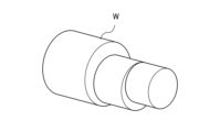
- FIG. 1 illustrates a workpiece produced by eccentric turning.
- FIG. 4 is a waveform diagram showing X-axis and Y-axis movements of a tool in eccentric turning.
- FIG. 13 is a diagram for explaining normal turning and servo learning oscillation turning.
- 4 is a flowchart showing the operation of a learning control unit of the servo motor control device of the first embodiment.
- FIG. 13 is a block diagram showing an example configuration of a learning control unit of a servo motor control device according to a second embodiment of the present disclosure.
- FIG. FIG. 11 is an explanatory diagram of a process of converting a position deviation ⁇ obtained during sampling by a time-position converter into a position deviation at a predetermined reference position ⁇ (n) of a reference position ⁇ in the second embodiment.
- FIG. 11 is a waveform diagram showing how a time-position converter converts a position deviation that is a function of time into a position deviation that is a function of a reference axis position in the second embodiment.
- FIG. 11 is a waveform diagram for explaining the sampling period of the position deviation, which is a function of time, and the division number of the position deviation, which is a function of the reference axis position, in the time-position converter in the second embodiment.
- 11 is a waveform diagram of a position deviation showing the relationship between the conversion process of a time-position converter and a position-time converter, and the filtering process of a band-limiting filter.
- FIG. 10 is a flowchart showing the operation of a learning control unit of the servo motor control device of the second embodiment.
- FIG. 13 is a block diagram showing an example configuration of a learning control unit of a servo motor control device according to a third embodiment of the present disclosure.
- FIG. 13 is a block diagram showing an example configuration of a learning control unit of a servo motor control device according to a fourth embodiment of the present disclosure.
- FIG. 13 is a block diagram showing an example configuration of a learning control unit of a servo motor control device according to a fifth embodiment of the present disclosure.
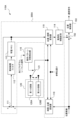
- Fig. 1 is a block diagram showing an example of the overall configuration of a servo motor control device according to a first embodiment of the present disclosure
- Fig. 2 is a block diagram showing an example of the configuration of a learning control unit.
- the servo motor control device 10 includes a servo motor control unit 100 and a learning control unit 110.
- the servo motor control unit 100 includes a subtractor 101, an adder 102, a position control unit 103, a subtractor 104, a speed control unit 105, a current control unit 106, a servo motor 107, and an integrator 108.
- the servo motor 107 is a motor with a rotating shaft or a linear motor.
- the object driven by the servo motor 107 is, for example, a mechanical part of a machine tool or industrial machine.
- the servo motor 107 may be provided as a part of the machine tool or industrial machine. In the following explanation, the case where the servo motor 107 is a motor with a rotating shaft will be explained.
- the learning control unit 110 includes an adder 111, a band-limiting filter 112, a learning memory 113, a dynamic characteristic compensation element 114, a cutoff frequency storage unit 115, an operation pattern switching detection unit 116, and a cutoff frequency switching unit 117.
- the adder 111, the band-limiting filter 112, the learning memory 113, and the dynamic characteristic compensation element 114 constitute a learning controller 200.
- FIG. 2 also shows the adder 102 and the position control unit 103 of the servo motor control unit 100.
- the learning control unit 110 may be provided as part of a machine tool, industrial machine, or the like, together with the servo motor control unit 100.
- the servo motor control unit 100 controls the operation of a machine tool or industrial machine by controlling the servo motor 107 based on a position command.
- the servo motor control unit 100 calculates the difference between the detected position detected by a position detector consisting of the servo motor 107 and integrator 108 and a position command input to the servo motor control unit 100 from a numerical control device or the like, and outputs this difference as a position deviation to the learning control unit 110.
- the servo motor control unit 100 adds the correction data output from the learning control unit 110 to the position deviation using the adder 102, and controls so that the position deviation converges to zero.
- the learning control unit 110 adds the correction data stored in the learning memory 113 to the input position deviation using an adder 111, band-limits the output from the adder 111 using a band-limiting filter 112, and stores the result as correction data in the learning memory 113.
- the learning control unit 110 stores correction data consisting of position deviation data in one pattern period of the same repeated command pattern in the learning memory 113, and in the next pattern period, outputs the correction data stored in the learning memory 113 to the adder 102 via the dynamic characteristic compensation element 114.
- the learning control unit 110 changes the cutoff frequency of the band-limiting filter 112 using a cutoff frequency storage unit 115, an operation pattern switch detection unit 116, and a cutoff frequency switch unit 117.
- the configurations and operations of the servo motor control unit 100 and the learning control unit 110 will be described in detail below.
- the speed control unit 105 performs PI control (Proportional-Integral Control), adds the integrated value of the speed deviation multiplied by integral gain K1v to the value of the speed deviation multiplied by proportional gain K2v, and outputs the result as a torque command to the current control unit 106.
- PI control Proportional-Integral Control
- PID control Proportional-Integral-Differential Control
- the current control unit 106 calculates the value of the current (current value) to be passed through the servo motor 107 based on the torque command, and controls the servo motor 107 based on this current value.
- the rotational speed of servo motor 107 is detected by a rotary encoder (not shown) provided on servo motor 107, and the detected speed is input to subtractor 104 as speed feedback.
- the detected position obtained by integrating the detected position in integrator 108 is input to subtractor 101 as position feedback (hereinafter referred to as position FB).
- position FB position feedback
- the rotary encoder serves as a speed detector, and the rotary encoder and integrator 108 serve as a position detector.
- the adder 111 shown in FIG. 2 adds the position deviation output from the servo motor control unit 100 and the correction data stored in the learning memory 113 , and outputs the sum to the band limiting filter 112 .
- the band-limiting filter 112 is a filter for stabilizing the learning control system, for example, a low-pass filter for cutting signals in the high-frequency range in a certain frequency domain, and stores the added value output from the adder 111 in the learning memory 113 as correction data.
- the position FB when the position command is a repetitive command, the position FB also has a repetitive waveform, and the position deviation, which is the difference between the position command and the position FB, also has a repetitive waveform synchronized with the position command.
- the band-limiting filter 112 when the position deviation includes a high-frequency disturbance that is not synchronized with the position command, the band-limiting filter 112 removes this disturbance and extracts the component synchronized with the position command, thereby stabilizing the learning control.
- the learning memory 113 stores the correction data from one previous period that has been subjected to band limiting processing by the band limiting filter 112.
- the correction data stored in the learning memory 113 is output to the adder 111 and also to the dynamic characteristic compensation element 114.
- the dynamic characteristic compensation element 114 compensates for the phase delay and gain reduction of the controlled object using the correction data, and outputs the result to the adder 102.
- the adder 102 adds the position deviation and the correction data output from the dynamic characteristic compensation element 114 to the position deviation, and outputs the result to the position control unit 103.
- a cutoff frequency corresponding to a plurality of different operation patterns is stored in the cutoff frequency storage unit 115.
- the cutoff frequency is a frequency at which the gain characteristic of the Bode diagram is ⁇ 3 dB, or a frequency at which the phase characteristic is ⁇ 180 degrees.
- 2 shows an example in which the cutoff frequency storage unit 115 stores two cutoff frequencies as a plurality of cutoff frequencies. As shown in FIG. 2, the cutoff frequency storage unit 115 includes a cutoff frequency storage unit 114A (shown as a first cutoff frequency 114A in FIG.
- the motion pattern switching detection unit 116 detects switching of the motion pattern between the first motion pattern P1 and the second motion pattern P2, and outputs a signal indicating that the switched motion pattern is either the first motion pattern P1 or the second motion pattern P2 to the cutoff frequency switching unit 117.
- the motion pattern switching detection unit 116 detects the motion pattern based on, for example, the G code of the machining program or a signal output from a numerical control device. Note that when the two different motion patterns are eccentric turning and servo learning oscillation, as described below, eccentric turning and servo learning oscillation each have their own dedicated G code in the machining program.
- the motion pattern switching detection unit 116 can detect the motion pattern by the dedicated G code of the machining program.
- the cutoff frequency switching unit 117 acquires the cutoff frequency corresponding to the post-switching operation pattern from the cutoff frequency storage unit 115 based on the input signal, and switches the cutoff frequency of the band-limiting filter 112 to the acquired cutoff frequency. For example, when the cutoff frequency of the band-limiting filter 112 is set to the second cutoff frequency F2, the operation pattern switching detection unit 116 detects that the operation pattern has changed from the second operation pattern P2 to the first operation pattern P1. In this case, the operation pattern switching detection unit 116 outputs a signal indicating the first operation pattern P1 to the cutoff frequency switching unit 117.
- the cutoff frequency switching unit 117 acquires the first cutoff frequency F1 corresponding to the first operation pattern P1 from the cutoff frequency storage unit 115, and switches the cutoff frequency of the band-limiting filter 112 from the second cutoff frequency F2 to the first cutoff frequency F1.
- the cutoff frequency of the band-limiting filter is automatically switched depending on the operation pattern by the cutoff frequency memory unit 115, operation pattern switching detection unit 116, and cutoff frequency switching unit 117 described above.
- FIG. 6 is a diagram showing the first and second operation patterns, the bands required for the first and second operation patterns, and the cutoff frequency of the band limiting filter 112.
- FIG. 6 is a diagram showing the first and second operation patterns, the bands required for the first and second operation patterns, and the cutoff frequency of the band limiting filter 112.
- the cutoff frequency of the band-limiting filter 112 is set to cutoff frequency F2.
- the servo motor control unit 100 operates in the band B2 required for the second operating pattern P2, as shown in FIG. 6, even if a disturbance of a frequency higher than the cutoff frequency F2 occurs, the disturbance is removed by the band-limiting filter 112.
- the servo motor control unit 100 operates in the band B1 required for the first operating pattern P1 if an asynchronous disturbance of a frequency higher than band B1 and lower than the cutoff frequency F2 occurs, the disturbance cannot be removed by the band-limiting filter 112 set to cutoff frequency F2. Therefore, the asynchronous disturbance causes the learning control of the learning controller 200 to become unstable.
- the servo motor control device 10 of the present embodiment aims to stabilize the learning control by switching the cutoff frequency in response to switching of the operation pattern.
- Two motion patterns requiring different bands include, for example, eccentric turning and servo learning oscillation in the case of machining motion patterns of a machine tool.
- Eccentric turning is a machining method in which one rotation of the workpiece (direction C in the figure) is synchronized with one circumference of the tool as shown in Fig. 7 to create a workpiece W shown in Fig. 8, which is offset from the center of the workpiece.
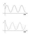
- the X-axis and Y-axis movements of the tool relative to the workpiece produce a repeating waveform as shown in the waveform diagram in Fig. 9, with the horizontal axis representing time.
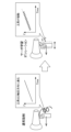
- Servo learning oscillation is a machining method in which the tool is oscillated in the feed direction during turning or drilling to shred the chips. For example, as shown in Figure 10, in normal turning, the tool advances at a constant speed in the Z direction, but in turning with servo learning oscillation, the tool advances by oscillating in the Z direction.
- the oscillation command is a command with a repeating pattern.
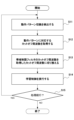
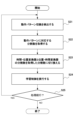
- FIG. 11 is a flowchart showing the operation of the learning control unit 110.
- the operation pattern switching detection unit 116 detects switching of the operation pattern and outputs a signal indicating that the switched operation pattern is the first operation pattern P1 or the second operation pattern P2 to the cutoff frequency switching unit 117.
- step S12 the cutoff frequency switching unit 117 acquires the first cutoff frequency F1 or the second cutoff frequency F2 corresponding to the first operation pattern P1 or the second operation pattern P2 after switching from the cutoff frequency memory unit 115 based on the input signal.
- the cutoff frequency memory unit 115 stores the first cutoff frequency F1 corresponding to the first operation pattern P1 in association with the first operation pattern P1, and stores the second cutoff frequency F2 corresponding to the second operation pattern P2 in association with the second operation pattern P2.
- the cutoff frequency switching unit 117 switches the cutoff frequency of the band-limiting filter 112 to the acquired cutoff frequency. For example, if the cutoff frequency of the band-limiting filter 112 is set to the second cutoff frequency F2 and the acquired cutoff frequency is the first cutoff frequency F1, the cutoff frequency switching unit 117 switches the cutoff frequency F2 of the band-limiting filter 112 to the first cutoff frequency F1.
- step S14 the adder 111, the band-limiting filter 112 switched to the acquired cutoff frequency, the learning memory 113, and the dynamic characteristic compensation element 114 perform learning control and output correction data to the adder 102.
- step S15 the learning control unit 110 determines whether to execute the process again, and if so, returns to step S11, and if not, ends the process.
- FIG. 13 is an explanatory diagram of the process of converting the position deviation ⁇ obtained during sampling by the time-position converter 118 into a position deviation at a predetermined reference position ⁇ (n) of the reference position ⁇ .
- the horizontal axis represents time (sampling time), and the upward direction of the vertical axis represents the reference position ⁇ . Also, the downward direction of the vertical axis represents the position deviation ⁇ .
- the position deviation obtained in the previous sampling period t(n-1) is ⁇ (n-1) and the reference position is ⁇ (n-1)
- the position deviation obtained in the current sampling period t(n) is ⁇ (n) and the reference position is ⁇ (n).
- the time-position converter 118 divides between the reference position ⁇ (n-1) and the reference position ⁇ (n) to obtain the reference position ⁇ (c), and interpolates the position deviation.
- FIG. 15 is a waveform diagram for explaining the sampling period of the position deviation, which is a function of time, and the division number of the position deviation, which is a function of the reference axis position, obtained by the time-position converter 118.
- the position error is sampled for each command generation period of the position command, that is, the sampling period of the position error is the same as the command generation period of the position command.
- the repetition period ⁇ of the position error after time-position conversion is 360°, as shown in FIG. 15, to match the sampling period of the position error to the scale of the division number, it is set to the division number calculated by Equation 2.
- the position-time converter 119 performs the reverse operation of the time-position converter 118. That is, the position-time converter 119 converts the position deviation (which becomes correction data) at a predetermined position ⁇ (n) in the reference position ⁇ into a position deviation ⁇ determined at a sampling period based on the input reference position ⁇ .
- the division numbers used in the conversion by the time-position converter 118 and the position-time converter 119 are set by the motion pattern switch detector 116 , the division number storage unit 120 and the division number switch unit 121 .
- the dynamic characteristic compensation element 114 compensates for the phase delay and gain reduction of the controlled object for the position deviation (correction data) that has been subjected to position-time conversion, and outputs the result to the adder 102.
- the adder 102 adds the position deviation and the correction data output from the dynamic characteristic compensation element 114 to the position deviation, and outputs the result to the position control unit 103.
- the division number storage unit 120 stores a number of division numbers corresponding to a number of different movement patterns.
- FIG. 12 shows an example in which the division number storage unit 120 includes a first division number storage unit 120A (shown as a first division number 1204A in FIG. 12) that stores a first division number D1 corresponding to a first movement pattern P1 in association with the first movement pattern P1, and a second division number storage unit 120B (shown as a second division number 1204B in FIG. 12) that stores a second division number D2 corresponding to a second movement pattern P2 in association with the second movement pattern P2, for two different movement patterns.
- a first division number storage unit 120A shown as a first division number 1204A in FIG. 12
- a second division number storage unit 120B shown as a second division number 1204B in FIG. 12
- the division number switching unit 121 obtains from the division number memory unit 120 the division number corresponding to the movement pattern output from the movement pattern switching detection unit 116, and switches the division numbers of the time-position converter 118 and the position-time converter 119 to the obtained division number. For example, when the division number of the time-position converter 118 and the position-time converter 119 is set to the second division number D2, the movement pattern switching detection unit 116 detects that the movement pattern has changed from the second movement pattern P2 to the first movement pattern P1. In this case, the movement pattern switching detection unit 116 outputs a signal indicating the first movement pattern P1 to the division number switching unit 121.
- the division number switching unit 121 acquires the first division number D1 corresponding to the first operation pattern P1 from the division number storage unit 120 based on a signal indicating the first operation pattern P1, and switches the division number of the time-position converter 118 and the position-time converter 119 from the second division number D2 to the first division number D1.
- the number of divisions of the time-position converter 118 and the position-time converter 119 are automatically switched depending on the operation pattern by the operation pattern switching detection unit 116, the division number storage unit 120, and the division number switching unit 121.
- FIG. 16 is a waveform diagram of the position deviation showing the relationship between the conversion process of the time-position converter 118 and the position-time converter 119 and the filtering process of the band-limiting filter 112.
- the position deviation before being band-limited by the band-limiting filter contains components with frequencies higher than the sampling period, and the position deviation after being band-limited by the band-limiting filter has had the high-frequency components removed.
- the black arrows indicate the actual processing paths in learning control
- the white arrows indicate the apparent processing paths converted into the time domain.
- the time-position converter 118 performs time-position conversion (conversion from the time domain to the position domain) of the position deviation using the division number set by the division number switching unit 121
- the band limiting filter 112 performs band limitation at the cutoff frequency F A
- the position-time converter 119 performs position-time conversion (conversion from the position domain to the time domain) of the band-limited position deviation using the division number set by the division number switching unit 121.
- the position-time converted position deviation is band-limited by the band limiting filter at the cutoff frequency F T shown in Equation 3 (Equation 3 below).
- the cutoff frequency F T becomes the actual response band.
- FIG. 17 is a flowchart showing the operation of the learning control unit 110A.
- step S21 the operation pattern switching detection unit 116 detects a switch in the operation pattern. Then, the operation pattern switching detection unit 116 outputs a signal indicating that the switched operation pattern is the first operation pattern P1 or the second operation pattern P2 to the division number switching unit 121.
- step S22 the division number switching unit 121 acquires the first division number D1 or the second division number D2 corresponding to the first operation pattern P1 or the second operation pattern P2 after switching from the division number storage unit 120 based on the input signal.
- the division number storage unit 120 stores the first division number D1 corresponding to the first operation pattern P1 in association with the first operation pattern P1, and stores the second division number D2 corresponding to the second operation pattern P2 in association with the second operation pattern P2.
- step S23 the division number switching unit 121 switches the division numbers of the time-position converter 118 and the position-time converter 119 to the acquired first division number D1 or second division number D2. For example, if the division numbers of the time-position converter 118 and the position-time converter 119 are set to the second division number D2 and the acquired division number is the first division number D1, the division number switching unit 121 switches the division number D2 of the time-position converter 118 and the position-time converter 119 to the first division number D1.
- step S24 the adder 111, the band-limiting filter 112, the learning memory 113, the position-time converter 119, and the dynamic characteristic compensation element 114 perform learning control and output correction data to the adder 102.
- step S25 the learning control unit 110A determines whether or not to execute the process again, and if the process is to be executed again, the process returns to step S21, and if the process is not to be executed again, the process ends.
- the learning control of the operation described above is called position synchronous learning control.
- the servo motor device of the second embodiment described above has the effect of stabilizing learning control for controls with different operating patterns. Furthermore, the servo motor device of the second embodiment has the effect of automatically switching the division numbers of the time-position converter and the position-time converter depending on the operating pattern, eliminating the need to manually switch the settings of the division numbers of the time-position converter and the position-time converter, thereby reducing the burden on the site.
- FIG. 18 is a block diagram showing an example configuration of a learning control unit of a servo motor control device according to a third embodiment of the present disclosure.
- the learning control unit 110 shown in Fig. 2 is replaced with a learning control unit 110B shown in Fig. 18.
- the configuration of the servo motor control unit of the servo motor control device according to this embodiment is the same as that of the servo motor control unit 100 according to the first embodiment.
- the learning control unit 110B has a configuration in which the time-position converter 118 and the position-time converter 119 of the learning controller 200 of the learning control unit 110A of the second embodiment are added to the learning control unit 110 of the first embodiment.
- the adder 111, the band-limiting filter 112, the learning memory 113, the dynamic characteristic compensation element 114, the time-position converter 118, and the position-time converter 119 constitute the learning controller 200A (not shown in FIG. 18).
- the number of divisions of the time-position converter 118 and the position-time converter 119 is configured to be switched in response to switching of the movement pattern by the movement pattern switching detection unit 116, the number of divisions storage unit 120, and the number of divisions switching unit 121.
- the number of divisions is set to one in the time-position converter 118 and the position-time converter 119.
- the operations of the time-position converter 118 and the position-time converter 119 have been described in the second embodiment, and therefore will not be described in this embodiment.
- the servo motor device of the third embodiment has the effect of stabilizing learning control for control with different operating patterns. And, in addition to the effect of the servo motor device of the first embodiment, the servo motor device of the third embodiment has the effect of making it possible to apply the learning control of the position synchronization method of the servo motor device of the second embodiment when the division number is one.
- FIG. 19 is a block diagram showing an example configuration of a learning control unit of a servo motor control device according to a fourth embodiment of the present disclosure.
- the learning control unit 110 shown in Fig. 2 is replaced with a learning control unit 110C shown in Fig. 19.
- the configuration of the servo motor control unit of the servo motor control device according to this embodiment is the same as that of the servo motor control unit 100 according to the first embodiment.
- the learning control unit 110C is configured by adding to the learning control unit 110 the time-position converter 118, position-time converter 119, division number storage unit 120, and division number switching unit 121 of the learning controller 200 of the learning control unit 110A shown in FIG. 12.
- the adder 111, band-limiting filter 112, learning memory 113, dynamic characteristic compensation element 114, time-position converter 118, and position-time converter 119 constitute the learning controller 200A (not shown in FIG. 19).
- the operation pattern switching detection unit 116 is connected to the cutoff frequency switching unit 117 and the division number switching unit 121, detects switching of the operation pattern, and outputs a signal indicating the switched operation pattern to the cutoff frequency switching unit 117 and the division number switching unit 121.
- the cutoff frequency switching unit 117 acquires the cutoff frequency corresponding to the operation pattern indicated by the signal output from the operation pattern switching detection unit 116 from the cutoff frequency memory unit 115, and switches the cutoff frequency of the band-limiting filter 112 to the acquired cutoff frequency.
- the division number switching unit 121 obtains the division number corresponding to the movement pattern indicated by the signal output from the movement pattern switching detection unit 116 from the division number storage unit 120, and switches the division numbers of the time-position converter 118 and the position-time converter 119 to the obtained division number.
- the learning band shown in formula 1 is the cutoff frequency set by the cutoff frequency switching unit 117
- the division number shown in formula 1 is the division number set by the division number switching unit 121.
- the servo motor device of the fourth embodiment has the effect of stabilizing learning control for control with different operating patterns. And, in addition to the effect of the servo motor device of the first embodiment, the servo motor device of the fourth embodiment has the effect of automatically switching the division numbers of the time-position converter and the position-time converter depending on the operating pattern, eliminating the need to manually switch the settings of the division numbers of the time-position converter and the position-time converter, thereby reducing the burden on the site.
- FIG. 20 is a block diagram showing an example configuration of a learning control unit of a servo motor control device according to a fifth embodiment of the present disclosure.
- the learning control unit 110B shown in FIG. 18 is replaced with a learning control unit 110D shown in FIG. 20.
- the configuration of the servo motor control unit of the servo motor control device according to this embodiment is the same as the servo motor control unit 100 according to the first embodiment.
- the learning control unit 110D has a configuration in which the cutoff frequency memory unit 115, the operation pattern switching detection unit 116, and the cutoff frequency switching unit 117 of the learning control unit 110B have been deleted, and an operation frequency acquisition unit 122, a magnification setting unit 123, and a cutoff frequency setting unit 124 have been added to the learning control unit 110B.
- the operating frequency acquisition unit 122 outputs the operating frequency to the cutoff frequency setting unit 124 based on the G code of the machining program or a signal output from the numerical control device.
- the magnification setting unit 123 sets a magnification by which the operating frequency is multiplied, and outputs the set magnification to the cutoff frequency setting unit 124.
- the magnification is set to 1 or more.
- the cutoff frequency setting unit 124 obtains the cutoff frequency by multiplying the operating frequency by a magnification factor, and sets the cutoff frequency of the band-limiting filter 112 .
- the servo motor device of the fifth embodiment has the effect of stabilizing learning control for controls with different operating frequencies. Furthermore, the servo motor device of the fifth embodiment has the effect of eliminating the need to manually change the cutoff frequency setting of the band-limiting filter, thereby reducing the burden on the site.
- the servo motor control device can be realized by hardware, software, or a combination of these.
- being realized by software means being realized by a computer reading and executing a program.
- each servo motor control device is equipped with an arithmetic processing device such as a CPU (Central Processing Unit).
- the servo motor control device also has a main storage device such as a RAM (Random Access Memory) for storing data temporarily required for the arithmetic processing device to execute a program.
- the servo motor control device disclosed herein, including each embodiment, can stabilize learning control for control with different operating patterns or operating frequencies.
- the scope of the present invention is not limited to only the above-described embodiments, and the present invention can be implemented in various modified forms without departing from the gist of the present invention.
- the fifth embodiment may be applied to the second embodiment.
- the cutoff frequency of the band-limiting filter 112 shown in FIG. 12 is set by the operating frequency acquisition unit 122, the magnification setting unit 123, and the cutoff frequency setting unit 124 shown in FIG. 20.
- a servo motor control device including a servo motor control unit (100) that drives a servo motor (107) with a plurality of periodic operation patterns for a feed axis, and a learning control unit (110, 110B) that corrects a position deviation of the servo motor control unit,
- the learning control unit (110, 110B) a learning controller (200, 200A) for storing correction data in a learning memory (113) by attenuating high frequency components of a position deviation in an operation pattern using a band limiting filter (112) and correcting the position deviation; a cutoff frequency storage unit (115) for storing a plurality of cutoff frequencies of the band limiting filter; an operation pattern switching detection unit (116) that determines which of a plurality of operation patterns is being executed and detects switching of the operation pattern; a cutoff frequency switching unit (117) that, when the operation pattern switching detection unit detects a switching of the operation pattern, acquires
- (Appendix 2) The servo motor control device according to claim 1, wherein the learning controller (200A) converts the position deviation for each sampling period in the operation pattern into position deviations at divided positions obtained by dividing the position range in the sampling period into a plurality of regions, attenuates high-frequency components of the converted position deviation using the band-limiting filter to create correction data, stores the created correction data in the learning memory, converts the correction data corresponding to the divided positions into correction data for each sampling period, and corrects the position deviation.
- the learning controller (200A) converts the position deviation for each sampling period in the operation pattern into position deviations at divided positions obtained by dividing the position range in the sampling period into a plurality of regions, attenuates high-frequency components of the converted position deviation using the band-limiting filter to create correction data, stores the created correction data in the learning memory, converts the correction data corresponding to the divided positions into correction data for each sampling period, and corrects the position deviation.
- a servo motor control device including a servo motor control unit (100) that drives a servo motor (107) with a plurality of periodic operation patterns for a feed axis, and a learning control unit (110A, 110C) that corrects a position deviation of the servo motor control unit,
- the learning control unit (110A, 110C) a learning controller (200A) that converts a position deviation for each sampling period in the operation pattern into a position deviation at a divided position obtained by dividing a position range in the sampling period into a plurality of regions, stores correction data created based on the converted position deviation in a learning memory (113), converts the correction data corresponding to the divided position into correction data for each sampling period, and corrects the position deviation;
- a division number storage unit 120) for storing a plurality of division numbers for dividing a position range in a sampling period into a plurality of regions; an operation pattern switching detection unit (116) that determines which of a plurality of operation patterns is being executed
- the learning controller (200A) includes a band-limiting filter (112) that attenuates high-frequency components of a position deviation in an operation pattern, and the correction data stored in the learning memory (113) is correction data created by attenuating high-frequency components using the band-limiting filter; a cutoff frequency storage unit (115) for storing a plurality of cutoff frequencies of the band limiting filter; a cutoff frequency switching unit (117) that, when the operation pattern switching detection unit (116) detects a switching of the operation pattern, acquires a cutoff frequency corresponding to the switched operation pattern from the cutoff frequency storage unit and switches the cutoff frequency of the band limiting filter to the acquired cutoff frequency; 4.
- the servo motor control device comprising:
- a servo motor control device including a servo motor control unit (100) that drives a servo motor (107) with a plurality of periodic operation patterns for a feed axis, and a learning control unit (110D) that corrects a position deviation of the servo motor control unit,
- the learning control unit (110D) a learning controller (200, 200A) for storing correction data in a learning memory (113) by attenuating high frequency components of a position deviation in an operation pattern using a band limiting filter (112) and correcting the position deviation;
- An operating frequency acquisition unit (122) for acquiring an operating frequency of an operating pattern;
- a magnification setting unit (123) that sets a magnification of the operating frequency;
- a cutoff frequency setting unit (124) that sets a cutoff frequency of the band limiting filter to a cutoff frequency obtained by multiplying the operating frequency by the magnification;
- a servo motor control device comprising:
- Servo motor control device 100 Servo motor control section 101 Subtractor 102 Adder 103 Position control section 104 Subtractor 105 Speed control section 106 Current control section 107 Servo motor 108 Integrator 110, 110A, 110B, 110C, 110D Learning control section 111 Adder 112 Band limiting filter 113 Learning memory 114 Dynamic characteristic compensation element 115 Cut-off frequency storage section 116 Operation pattern switching detection section 117 Cut-off frequency switching section 118 Time-position converter 119 Position-time converter 120 Division number storage section 121 Division number switching section 200, 200A Learning controller
Landscapes
- Engineering & Computer Science (AREA)
- Power Engineering (AREA)
- Control Of Electric Motors In General (AREA)
Abstract
動作パターン又は動作周波数の異なる制御に対し、学習制御を安定化させる。 送り軸を複数の周期的な動作パターンでサーボモータを駆動するサーボモータ制御装置において、位置偏差を補正する学習制御部の帯域制限フィルタのカットオフ周波数を、動作パターンの切り替わりに対応して、動作パターンに応じたカットオフ周波数に切り換えるか又は動作パターンの動作周波数に設定された倍率を掛けたカットオフ周波数に設定する。送り軸を複数の周期的な動作パターンでサーボモータを駆動するサーボモータ制御装置の、位置偏差を補正する学習制御部で、サンプリング周期毎の位置偏差と、サンプリング周期における位置での位置偏差との間で変換を行うときの分割数を、動作パターンの切り替わりに対応して、動作パターンに応じた分割数に切り換える。
Description
本開示は、送り軸を複数の周期的な動作パターンでサーボモータを駆動するサーボモータ制御装置に関する。
工作機械又は産業機械において用いられる、サーボモータ制御装置となるサーボモータ制御装置において、周期的な動作パターンの指令によって加工等を行う場合、学習制御により、位置偏差を零近くまで収束させて加工精度を向上させるサーボモータ制御装置が、例えば、特許文献1に記載されている。
具体的には、特許文献1には、数値制御装置が、基準角度θ(=ωt)を計算する基準角度計算手段と、基準角度θと加工条件に基づいて周期的な揺動指令F(t)を計算する揺動指令計算手段と、を備え、サーボ制御装置が、サンプリング周期毎に前記揺動指令F(t)とサーボモータの位置を検出する位置検出手段からの位置フィードバックPfとの偏差である位置偏差εを演算する演算器と、基準角度θと揺動指令F(t)と位置偏差εに基づいて学習制御を行う学習制御手段と、を備え、周期的な高速揺動を行う被駆動体をサーボモータを用いて駆動する工作機械あるいは産業機械の該サーボモータを駆動制御するサーボモータ駆動制御システムが記載されている。
具体的には、特許文献1には、数値制御装置が、基準角度θ(=ωt)を計算する基準角度計算手段と、基準角度θと加工条件に基づいて周期的な揺動指令F(t)を計算する揺動指令計算手段と、を備え、サーボ制御装置が、サンプリング周期毎に前記揺動指令F(t)とサーボモータの位置を検出する位置検出手段からの位置フィードバックPfとの偏差である位置偏差εを演算する演算器と、基準角度θと揺動指令F(t)と位置偏差εに基づいて学習制御を行う学習制御手段と、を備え、周期的な高速揺動を行う被駆動体をサーボモータを用いて駆動する工作機械あるいは産業機械の該サーボモータを駆動制御するサーボモータ駆動制御システムが記載されている。
送り軸を複数の周期的な動作パターンでサーボモータを駆動するサーボモータ制御装置において、動作パターンの帯域が異なる複数の動作を行う場合に、学習制御が不安定になる場合がある。
よって、動作パターンの帯域の異なる複数の動作を行うとする場合に、学習制御を安定して行うことができるサーボモータ制御装置が望まれる。
本開示の代表的な第1の態様は、送り軸を複数の周期的な動作パターンでサーボモータを駆動するサーボモータ制御部と、該サーボモータ制御部の位置偏差を補正する学習制御部とを備えたサーボモータ制御装置であって、
前記学習制御部は、
動作パターンにおける位置偏差の高周波成分を帯域制限フィルタにより減衰させて作成した補正データを、学習メモリに記憶し、位置偏差を補正する学習制御器と、
前記帯域制限フィルタの複数のカットオフ周波数を記憶するカットオフ周波数記憶部と、
複数の動作パターンのどれが実行中かを判別し、動作パターンの切り換わりを検出する動作パターン切換検出部と、
前記動作パターン切換検出部で前記動作パターンの切り替わりを検出した場合に、切り換えられた動作パターンに応じたカットオフ周波数を前記カットオフ周波数記憶部から取得して、前記帯域制限フィルタのカットオフ周波数を、取得したカットオフ周波数に切り換えるカットオフ周波数切換部と、
を備える、サーボモータ制御装置である。
本開示の代表的な第2の態様は、送り軸を複数の周期的な動作パターンでサーボモータを駆動するサーボモータ制御部と、該サーボモータ制御部の位置偏差を補正する学習制御部とを備えたサーボモータ制御装置であって、
前記学習制御部は、
動作パターンにおけるサンプリング周期毎の位置偏差から、サンプリング周期における位置の範囲を複数の領域に分割した分割位置での位置偏差に変換し、変換した位置偏差に基づいて作成した補正データを、学習メモリに記憶し、分割位置に対応する補正データからサンプリング周期毎の補正データに変換し、位置偏差を補正する学習制御器と、
前記サンプリング周期における位置の範囲を前記複数の領域に分割する分割数を複数記憶する分割数記憶部と、
複数の動作パターンのどれが実行中かを判別し、動作パターンの切り換わりを検出する動作パターン切換検出部と、
前記動作パターン切換検出部で前記動作パターンの切り替わりを検出した場合に、切り換えられた動作パターンに応じた分割数を前記分割数記憶部から取得して、前記学習制御器で分割を行う分割数を取得した分割数に切り換える分割数切換部と、
を備える、サーボモータ制御装置である。
本開示の代表的な第3の態様は、送り軸を複数の周期的な動作パターンでサーボモータを駆動するサーボモータ制御部と、該サーボモータ制御部の位置偏差を補正する学習制御部とを備えたサーボモータ制御装置であって、
前記学習制御部は、
動作パターンにおける位置偏差の高周波成分を帯域制限フィルタにより減衰させて作成した補正データを、学習メモリに記憶し、位置偏差を補正する学習制御器と、
動作パターンの動作周波数を取得する動作周波数取得部と、
前記動作周波数の倍率を設定する倍率設定部と、
前記帯域制限フィルタのカットオフ周波数を、前記動作周波数に前記倍率を掛けて得られるカットオフ周波数に設定するカットオフ周波数設定部と、
を備える、サーボモータ制御装置である。
前記学習制御部は、
動作パターンにおける位置偏差の高周波成分を帯域制限フィルタにより減衰させて作成した補正データを、学習メモリに記憶し、位置偏差を補正する学習制御器と、
動作パターンの動作周波数を取得する動作周波数取得部と、
前記動作周波数の倍率を設定する倍率設定部と、
前記帯域制限フィルタのカットオフ周波数を、前記動作周波数に前記倍率を掛けて得られるカットオフ周波数に設定するカットオフ周波数設定部と、
を備える、サーボモータ制御装置である。
以下、本開示の実施形態について図面を用いて詳細に説明する。
(第1実施形態)
図1は本開示の第1の実施形態のサーボモータ制御装置の全体構成例を示すブロック図である。図2は、学習制御部の構成例を示すブロック図である。
サーボモータ制御装置10は、図1に示すように、サーボモータ制御部100及び学習制御部110を備えている。
(第1実施形態)
図1は本開示の第1の実施形態のサーボモータ制御装置の全体構成例を示すブロック図である。図2は、学習制御部の構成例を示すブロック図である。
サーボモータ制御装置10は、図1に示すように、サーボモータ制御部100及び学習制御部110を備えている。
サーボモータ制御部100は、図1に示すように、減算器101、加算器102、位置制御部103、減算器104、速度制御部105、電流制御部106、サーボモータ107及び積分器108を備えている。サーボモータ107は、回転軸を有するモータ又はリニアモータ等を用いる。サーボモータ107によって駆動される対象は、例えば、工作機械又は産業機械の機構部である。サーボモータ107は、工作機械又は産業機械等の一部として設けられてもよい。以下の説明では、サーボモータ107が回転軸を有するモータである場合について説明する。
学習制御部110は、図2に示すように、加算器111、帯域制限フィルタ112、学習メモリ113、動特性補償要素114、カットオフ周波数記憶部115、動作パターン切換検出部116及びカットオフ周波数切換部117を備えている。加算器111、帯域制限フィルタ112、学習メモリ113及び動特性補償要素114は学習制御器200を構成する。図2では、サーボモータ制御部100の加算器102及び位置制御部103も示されている。学習制御部110は、サーボモータ制御部100とともに、工作機械又は産業機械等の一部として設けられてもよい。
まず、サーボモータ制御部100及び学習制御部110の動作の概要について説明する。
サーボモータ制御部100は、位置指令に基づいてサーボモータ107を制御することで、工作機械又は産業機械の動作を制御する。サーボモータ制御部100は、サーボモータ107及び積分器108からなる位置検出器で検出された検出位置と、サーボモータ制御部100に数値制御装置等から入力される位置指令との差を求め、その差を位置偏差として、学習制御部110に出力する。サーボモータ制御部100は、学習制御部110から出力された補正データを、加算器102で位置偏差に加算して、位置偏差が零に収束するように制御する。
学習制御部110は、加算器111で、入力される位置偏差に学習メモリ113に記憶された補正データを可算し、加算器111からの出力を帯域制限フィルタ112によって帯域制限し、補正データとして学習メモリ113に記憶する。学習制御部110は、学習メモリ113に、繰り返される同一指令パターンの1パターン周期における位置偏差データからなる補正データを記憶し、次のパターン周期において、学習メモリ113に記憶する補正データを、動特性補償要素114を介して、加算器102に出力する。学習制御部110は、繰り返される同一指令パターンが異なる指令パターンになり、動作パターンが変わった場合、カットオフ周波数記憶部115、動作パターン切換検出部116及びカットオフ周波数切換部117を用いて、帯域制限フィルタ112のカットオフ周波数を変更する。
以下、サーボモータ制御部100及び学習制御部110の構成及び動作の詳細について説明する。
以下、サーボモータ制御部100及び学習制御部110の構成及び動作の詳細について説明する。
(サーボモータ制御部100)
図1に示す、減算器101は、入力された位置指令と位置フィードバックされた検出位置との差を求め、その差を位置偏差として学習制御部110及び加算器102に出力する。
加算器102は、位置偏差と、学習制御部110から出力された補正データを位置偏差に加算して、位置制御部103に出力する。
図1に示す、減算器101は、入力された位置指令と位置フィードバックされた検出位置との差を求め、その差を位置偏差として学習制御部110及び加算器102に出力する。
加算器102は、位置偏差と、学習制御部110から出力された補正データを位置偏差に加算して、位置制御部103に出力する。
位置制御部103は、位置偏差にポジションゲインKpを乗じた値を、速度指令値として減算器104に出力する。
減算器104は、速度指令値と、速度フィードバックされた速度検出値との差を求め、その差を速度偏差として速度制御部105に出力する。
減算器104は、速度指令値と、速度フィードバックされた速度検出値との差を求め、その差を速度偏差として速度制御部105に出力する。
速度制御部105は、PI制御(Proportional-Integral Control)を行い、速度偏差に積分ゲインK1vを乗じて積分した値と、速度偏差に比例ゲインK2vを乗じた値とを加算して、トルク指令として電流制御部106に出力する。速度制御部105は、特にPI制御に限定されず、他の制御、例えばPID制御(Proportional-Integral-Differential Control)を用いてもよい。
電流制御部106は、トルク指令に基づいてサーボモータ107に流す電流の値(電流値)を算出し、この電流値に基づいてサーボモータ107を制御する。
サーボモータ107の回転速度は、サーボモータ107に設けられたロータリーエンコーダ(図示せず)によって検出され、検出速度は速度フィードバックとして減算器104に入力される。検出位置を積分器108で積分して得られる検出位置は、位置フィードバック(以下、位置FBと記す)として減算器101に入力される。ロータリーエンコーダは速度検出器となり、ロータリーエンコーダと積分器108は位置検出器となる。
(学習制御部110)
まず、加算器111、帯域制限フィルタ112、学習メモリ113、及び動特性補償要素114を備えた学習制御器200の構成及び動作について説明する。
図2に示す加算器111は、サーボモータ制御部100から出力された位置偏差と、学習メモリ113に記憶された補正データとを加算して、その加算値を帯域制限フィルタ112に出力する。
帯域制限フィルタ112は、学習制御系の安定化を図るためのフィルタ、例えば、ある周波数領域における高周波数領域の信号をカットするためのローパスフィルタであり、加算器111から出力される、加算値を補正データとして学習メモリ113に記憶する。
まず、加算器111、帯域制限フィルタ112、学習メモリ113、及び動特性補償要素114を備えた学習制御器200の構成及び動作について説明する。
図2に示す加算器111は、サーボモータ制御部100から出力された位置偏差と、学習メモリ113に記憶された補正データとを加算して、その加算値を帯域制限フィルタ112に出力する。
帯域制限フィルタ112は、学習制御系の安定化を図るためのフィルタ、例えば、ある周波数領域における高周波数領域の信号をカットするためのローパスフィルタであり、加算器111から出力される、加算値を補正データとして学習メモリ113に記憶する。
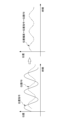
図3に示すように、位置指令が繰り返し指令の場合、位置FBも繰り返し波形となり、位置指令と位置FBとの差である位置偏差も、位置指令に同期した繰り返し波形になる。
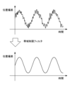
図4に示すように、位置偏差が、位置指令に同期しない高周波の外乱を含む場合に、帯域制限フィルタ112は、この外乱を除去し、位置指令に同期した成分を抽出することで学習制御を安定化させる。
図4に示すように、位置偏差が、位置指令に同期しない高周波の外乱を含む場合に、帯域制限フィルタ112は、この外乱を除去し、位置指令に同期した成分を抽出することで学習制御を安定化させる。
学習メモリ113は、帯域制限フィルタ112で帯域制限処理を行った、一周期前の補正データを記憶する。学習メモリ113に記憶された補正データは加算器111に出力されるとともに、動特性補償要素114に出力される。
動特性補償要素114は、補正データについて、制御対象の位相遅れ、ゲイン低下の補償を行い、加算器102に出力する。加算器102は、位置偏差と、動特性補償要素114から出力された補正データを位置偏差に加算して、位置制御部103に出力する。
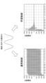
図5に示すように、学習制御部110を設けないサーボモータ制御装置10の制御(通常制御と記す)では、位置指令として繰り返し指令が入力されると、位置偏差の収束が遅い。しかし、加算器111、帯域制限フィルタ112、学習メモリ113及び動特性補償要素114を含む学習制御部110を設けたサーボモータ制御装置10の制御(学習制御と記す)では、図5に示すように、繰り返し命令に高速、高精度で追従し、位置偏差の収束が早い。
次に、カットオフ周波数記憶部115、動作パターン切換検出部116及びカットオフ周波数切換部117の構成及び動作について説明する。
カットオフ周波数記憶部115は、複数の異なる動作パターンに対応する複数のカットオフ周波数を記憶している。カットオフ周波数とは、ボーデ線図のゲイン特性が-3dBとなる周波数、又は位相特性が-180度となる周波数である。
図2は、カットオフ周波数記憶部115が、複数のカットオフ周波数として、2つのカットオフ周波数を記憶する例を示している。図2に示すように、カットオフ周波数記憶部115は、2つの異なる動作パターンに対して、第1の動作パターンP1に対応する第1のカットオフ周波数F1を、第1の動作パターンP1に紐づけて記憶するカットオフ周波数記憶部114A(図2では第1カットオフ周波数114Aとして示す)と、第2の動作パターンP2に対応する第2のカットオフ周波数F2を、第2の動作パターンP2に紐づけて記憶する第2のカットオフ周波数記憶部114B(図2では第2カットオフ周波数114Bとして示す)とを備えている。2つの異なる動作パターンの具体例については後述する。
図2は、カットオフ周波数記憶部115が、複数のカットオフ周波数として、2つのカットオフ周波数を記憶する例を示している。図2に示すように、カットオフ周波数記憶部115は、2つの異なる動作パターンに対して、第1の動作パターンP1に対応する第1のカットオフ周波数F1を、第1の動作パターンP1に紐づけて記憶するカットオフ周波数記憶部114A(図2では第1カットオフ周波数114Aとして示す)と、第2の動作パターンP2に対応する第2のカットオフ周波数F2を、第2の動作パターンP2に紐づけて記憶する第2のカットオフ周波数記憶部114B(図2では第2カットオフ周波数114Bとして示す)とを備えている。2つの異なる動作パターンの具体例については後述する。
以下の説明では、動作パターン切換検出部116及びカットオフ周波数切換部117が、第1のカットオフ周波数F1と第2のカットオフ周波数F2とを切り換える場合について説明する。
動作パターン切換検出部116は、第1の動作パターンP1と第2の動作パターンP2の間の動作パターンの切り換えを検出して、切り換わった動作パターンが第1の動作パターンP1か第2の動作パターンP2を示す信号をカットオフ周波数切換部117に出力する。動作パターン切換検出部116は、例えば、加工プログラムのGコード、又は数値制御装置から出力された信号に基づいて、動作パターンを検出する。なお、2つの異なる動作パターンが、後述するように、偏心ターニングとサーボ学習オシレーションである場合、偏心ターニングとサーボ学習オシレーションは、それぞれ加工プログラムに専用のGコードを用意している。動作パターン切換検出部116は、加工プログラムの専用のGコードによって動作パターンを検出できる。
カットオフ周波数切換部117は、入力された信号に基づいて、切り換え後の動作パターンに対応するカットオフ周波数をカットオフ周波数記憶部115から取得して、帯域制限フィルタ112のカットオフ周波数を、取得したカットオフ周波数に切り換える。例えば、帯域制限フィルタ112のカットオフ周波数が第2のカットオフ周波数F2に設定されていた場合、動作パターン切換検出部116が、動作パターンが第2の動作パターンP2から第1の動作パターンP1に変わったことを検出したとする。この場合、動作パターン切換検出部116は第1の動作パターンP1を示す信号をカットオフ周波数切換部117に出力する。カットオフ周波数切換部117は、第1の動作パターンP1に対応する第1のカットオフ周波数F1をカットオフ周波数記憶部115から取得して、帯域制限フィルタ112のカットオフ周波数を第2のカットオフ周波数F2から第1のカットオフ周波数F1に切り換える。
以上説明した、カットオフ周波数記憶部115、動作パターン切換検出部116及びカットオフ周波数切換部117により、帯域制限フィルタのカットオフ周波数が、動作パターンによって、自動的に切り換わる。
以下、動作パターンに対応してカットオフ周波数を切り換える理由について説明する。
図6は、第1及び第2の動作パターン、第1及び第2の動作パターンに必要な帯域、及び帯域制限フィルタ112のカットオフ周波数を示す図である。
図6は、第1及び第2の動作パターン、第1及び第2の動作パターンに必要な帯域、及び帯域制限フィルタ112のカットオフ周波数を示す図である。
帯域制限フィルタ112のカットオフ周波数は、カットオフ周波数F2に設定されているとする。サーボモータ制御部100が第2の動作パターンP2に必要な帯域B2で動作するときは、図6に示すように、カットオフ周波数F2よりも高い周波数の外乱が生じても、その外乱は帯域制限フィルタ112により除去される。しかし、サーボモータ制御部100が第1の動作パターンP1に必要な帯域B1で動作するときは、帯域B1よりも高く、カットオフ周波数F2より低い周波数の非同期の外乱が生じると、その外乱はカットオフ周波数F2に設定された帯域制限フィルタ112では除去できない。そのため、その非同期の外乱により、学習制御器200の学習制御が不安定になる。
図6に示すように、第1の動作パターンP1の場合は、帯域制限フィルタ112のカットオフ周波数がカットオフ周波数F1に設定され、第2の動作パターンP2の場合は帯域制限フィルタ112のカットオフ周波数がカットオフ周波数F2に設定されることが望ましい。
そこで、本実施形態のサーボモータ制御装置10は、動作パターンの切り換えに対応してカットオフ周波数を切り換えることで、学習制御の安定化を図る。
そこで、本実施形態のサーボモータ制御装置10は、動作パターンの切り換えに対応してカットオフ周波数を切り換えることで、学習制御の安定化を図る。
以下、2つの動作パターンの具体例について説明する。
必要な帯域が異なる2つの動作パターンとしては、例えば、工作機械の加工動作パターンの場合、偏心ターニングとサーボ学習オシレーションとがある。
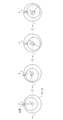
偏心ターニングは、図7に示すように、加工対象物となるワークの1回転(図のC方向)と工具の1周円を同期させて、ワーク中心からずれた形状の、図8に示す加工物Wを作成する加工方法である。ワークに対する工具のX軸移動とY軸移動は、横軸を時間にすると図9の波形図に示すような繰り返し波形になる。
必要な帯域が異なる2つの動作パターンとしては、例えば、工作機械の加工動作パターンの場合、偏心ターニングとサーボ学習オシレーションとがある。
偏心ターニングは、図7に示すように、加工対象物となるワークの1回転(図のC方向)と工具の1周円を同期させて、ワーク中心からずれた形状の、図8に示す加工物Wを作成する加工方法である。ワークに対する工具のX軸移動とY軸移動は、横軸を時間にすると図9の波形図に示すような繰り返し波形になる。
サーボ学習オシレーションは、旋削加工、又は穴あけ加工において、送り方向に工具を揺動させて切り屑を細断する加工方法である。例えば、図10に示すように、旋削加工において、通常の旋削では工具はZ方向に一定速度で進むが、サーボ学習オシレーションの旋削では工具はZ方向に揺動して進む。揺動指令は繰り返しパターンの指令となる。
次に、学習制御部110の動作についてフローチャートを用いて説明する。以下の説明では、動作パターン切換検出部116及びカットオフ周波数切換部117が、第1のカットオフ周波数F1と第2のカットオフ周波数F2とを切り換える場合について説明する。
図11は、学習制御部110の動作を示すフローチャートである。
ステップS11において、動作パターン切換検出部116は、動作パターンの切り換えを検出する。そして、動作パターン切換検出部116は、切り換わった動作パターンが第1の動作パターンP1か第2の動作パターンP2を示す信号をカットオフ周波数切換部117に出力する。
ステップS11において、動作パターン切換検出部116は、動作パターンの切り換えを検出する。そして、動作パターン切換検出部116は、切り換わった動作パターンが第1の動作パターンP1か第2の動作パターンP2を示す信号をカットオフ周波数切換部117に出力する。
ステップS12において、カットオフ周波数切換部117は、入力された信号に基づいて、切り換え後の第1の動作パターンP1又は第2の動作パターンP2に対応する、第1のカットオフ周波数F1又は第2のカットオフ周波数F2をカットオフ周波数記憶部115から取得する。カットオフ周波数記憶部115は、第1の動作パターンP1に対応する第1のカットオフ周波数F1を第1の動作パターンP1に紐づけて記憶し、第2の動作パターンP2に対応する第2のカットオフ周波数F2を第2の動作パターンP2に紐づけて記憶している。
ステップS13において、カットオフ周波数切換部117は、帯域制限フィルタ112のカットオフ周波数を、取得したカットオフ周波数に切り換える。例えば、帯域制限フィルタ112のカットオフ周波数が第2のカットオフ周波数F2に設定され、取得したカットオフ周波数が第1のカットオフ周波数F1であった場合、カットオフ周波数切換部117は、帯域制限フィルタ112のカットオフ周波数F2を第1のカットオフ周波数F1に切り換える。
ステップS14において、加算器111、取得したカットオフ周波数に切り換えられた帯域制限フィルタ112、学習メモリ113及び動特性補償要素114は、学習制御を行って補正データを加算器102に出力する。
ステップS15において、学習制御部110は、処理を再度実行するかどうかを判断し、処理を実行する場合はステップS11に戻り、処理を実行しない場合は処理を終了する。
以上説明した第1の実施形態のサーボモータ装置によれば、動作パターンの異なる制御に対し、学習制御を安定化させる効果がある。そして、第1の実施形態のサーボモータ装置によれば、帯域制限フィルタのカットオフ周波数が、動作パターンによって、自動的に切り換わるので、カットオフ周波数の設定を手動で切りかえる手間が省け、現場の負担を軽減することができる効果がある。
(第2実施形態)
第1の実施形態では、帯域制限フィルタ112のカットオフ周波数を動作パターンによって切り換えを行うことで、学習制御の学習帯域を変更していた。本実施形態では、学習制御の学習帯域を変更することなく、学習制御の実際の応答帯域を別な方法で変更する例について説明する。
図12は本開示の第2の実施形態のサーボモータ制御装置の学習制御部の構成例を示すブロック図である。本開示の第2の実施形態のサーボモータ制御装置は、図2に示した学習制御部110が図12に示す学習制御部110Aに置き換わっている。本実施形態のサーボモータ制御装置のサーボモータ制御部の構成は、第1の実施形態のサーボモータ制御部100と同じである。
第1の実施形態では、帯域制限フィルタ112のカットオフ周波数を動作パターンによって切り換えを行うことで、学習制御の学習帯域を変更していた。本実施形態では、学習制御の学習帯域を変更することなく、学習制御の実際の応答帯域を別な方法で変更する例について説明する。
図12は本開示の第2の実施形態のサーボモータ制御装置の学習制御部の構成例を示すブロック図である。本開示の第2の実施形態のサーボモータ制御装置は、図2に示した学習制御部110が図12に示す学習制御部110Aに置き換わっている。本実施形態のサーボモータ制御装置のサーボモータ制御部の構成は、第1の実施形態のサーボモータ制御部100と同じである。
学習制御部110Aは、学習制御部110のカットオフ周波数記憶部115及びカットオフ周波数切換部117が削除され、学習制御部110に、時間-位置変換器118、位置-時間変換器119、分割数記憶部120及び分割数切換部121が加えられた構成となっている。加算器111、帯域制限フィルタ112、学習メモリ113、動特性補償要素114、時間-位置変換器118、及び位置-時間変換器119は学習制御器200Aを構成する。時間-位置変換器118及び位置-時間変換器119の動作は、例えば、特許第4043996号に記載されている。以下の説明では、第1の実施形態のサーボモータ制御装置と異なる、時間-位置変換器118、位置-時間変換器119、分割数記憶部120及び分割数切換部121の構成、及びかかる構成に関する動作について説明し、第1の実施形態と重複する構成及び動作の説明は省略する。
時間-位置変換器118は、所定サンプリング周期毎(位置、速度ループ処理周期毎)の位置偏差εを、入力される参照位置θにおける所定位置θ(n)に対する位置偏差に変換する。nは0又は自然数を示す。参照位置θは、サーボモータ107で駆動制御される被駆動体と同期する基準となる位置である。参照位置θは、例えば、サーボモータ107に指令される位置指令、又は位置検出器からのフィードバック位置である。位置偏差εは所定サンプリング周期(位置、速度ループ処理周期)毎に求められ、時間の関数として求められ、被駆動体の位置又はサーボモータの回転位置に対応して求められるものではない。そこで、時間-位置変換器118は、サンプリング周期で求めた位置偏差εを参照位置θに基づいて、参照位置θにおける予め決められている所定位置θ(n)における位置偏差に変換する。
図13は、時間-位置変換器118によるサンプリング時に得られた位置偏差εを参照位置θの所定の参照位置θ(n)における位置偏差に変換する処理の説明図である。横軸は時間(サンプリング時間)、縦軸の上方向は、参照位置θを示す。又、縦軸の下方向は、位置偏差εを表す。
前回のサンプリング周期t(n-1)で求められた位置偏差がε(n-1)、参照位置がθ(n-1)であり、今回のサンプリング周期t(n)において求められた位置偏差がε(n)、参照位置がθ(n)とする。時間-位置変換器118は、参照位置θ(n-1)と参照位置θ(n)と間を分割して参照位置θ(c)を求めて位置偏差を補間する。
前回のサンプリング周期t(n-1)で求められた位置偏差がε(n-1)、参照位置がθ(n-1)であり、今回のサンプリング周期t(n)において求められた位置偏差がε(n)、参照位置がθ(n)とする。時間-位置変換器118は、参照位置θ(n-1)と参照位置θ(n)と間を分割して参照位置θ(c)を求めて位置偏差を補間する。
学習制御では、安定化のため帯域制限フィルタ112により、学習制御の応答帯域(周波数)を制限する。帯域制限フィルタ112のカットオフ周波数を学習帯域と呼ぶ。
本実施形態では、参照位置θ(n-1)と参照位置θ(n)と間の分割数を考慮して、学習制御の実際の応答帯域(カットオフ周波数)を求める。
実際の応答帯域は、数式1(以下の数1)で求められる。数式1の参照軸速度[Hz]は、1秒当たりの参照軸の回転数を表す。参照軸は、学習したい動作パターンに同期した軸を示し、図7に示す偏心ターニングでは、ワーク回転主軸が参照軸となる。

分割数が、数式2(以下の数2)の関係にあるときは、実際の応答帯域は学習帯域となる。実際の応答帯域が学習帯域である場合は、カットオフ周波数切換部117で設定されるカットオフ周波数によって、実際の応答帯域が決まることになる。実際の応答帯域の意味については後述する。

なお、参照軸速度は加工条件により変化する場合があり、分割数は、必ずしも数式2のように設定することができない場合がある。
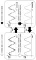
図14は、時間-位置変換器118が時間の関数である位置偏差を参照軸位置の関数である位置偏差に変換する様子を示す波形図である。
時間-位置変換器118は、図14に示すように、参照軸位置ωの範囲を分割して、分割した位置偏差を加算器111に出力する。
図15は、時間-位置変換器118が、時間の関数である位置偏差のサンプリング周期と、参照軸位置の関数である位置偏差の分割数を説明するための波形図である。
位置偏差は、位置指令の指令生成周期毎にサンプリングされる。つまり、位置偏差のサンプリング周期は、位置指令の指令生成周期と同じになる。
時間-位置変換後の位置偏差の繰り返し周期ωが360°の場合、図15に示すように、位置偏差のサンプリング周期を分割数の目盛りに合わせる場合、数式2で求められる分割数に設定する。
本実施形態では、参照位置θ(n-1)と参照位置θ(n)と間の分割数を考慮して、学習制御の実際の応答帯域(カットオフ周波数)を求める。
実際の応答帯域は、数式1(以下の数1)で求められる。数式1の参照軸速度[Hz]は、1秒当たりの参照軸の回転数を表す。参照軸は、学習したい動作パターンに同期した軸を示し、図7に示す偏心ターニングでは、ワーク回転主軸が参照軸となる。
分割数が、数式2(以下の数2)の関係にあるときは、実際の応答帯域は学習帯域となる。実際の応答帯域が学習帯域である場合は、カットオフ周波数切換部117で設定されるカットオフ周波数によって、実際の応答帯域が決まることになる。実際の応答帯域の意味については後述する。
図14は、時間-位置変換器118が時間の関数である位置偏差を参照軸位置の関数である位置偏差に変換する様子を示す波形図である。
時間-位置変換器118は、図14に示すように、参照軸位置ωの範囲を分割して、分割した位置偏差を加算器111に出力する。
図15は、時間-位置変換器118が、時間の関数である位置偏差のサンプリング周期と、参照軸位置の関数である位置偏差の分割数を説明するための波形図である。
位置偏差は、位置指令の指令生成周期毎にサンプリングされる。つまり、位置偏差のサンプリング周期は、位置指令の指令生成周期と同じになる。
時間-位置変換後の位置偏差の繰り返し周期ωが360°の場合、図15に示すように、位置偏差のサンプリング周期を分割数の目盛りに合わせる場合、数式2で求められる分割数に設定する。
位置-時間変換器119は、時間-位置変換器118とは逆の動作を行う。すなわち、位置-時間変換器119は、参照位置θにおける予め決められている所定位置θ(n)における位置偏差(補正データとなる)を、入力される参照位置θに基づいて、サンプリング周期で求める位置偏差εに変換する。
時間-位置変換器118及び位置-時間変換器119の変換で用いられる分割数は、動作パターン切換検出部116、分割数記憶部120及び分割数切換部121で設定される。
動特性補償要素114は、位置-時間変換された位置偏差(補正データ)について、制御対象の位相遅れ、ゲイン低下の補償を行い、加算器102に出力する。加算器102は、位置偏差と、動特性補償要素114から出力された補正データを位置偏差に加算して、位置制御部103に出力する。
時間-位置変換器118及び位置-時間変換器119の変換で用いられる分割数は、動作パターン切換検出部116、分割数記憶部120及び分割数切換部121で設定される。
動特性補償要素114は、位置-時間変換された位置偏差(補正データ)について、制御対象の位相遅れ、ゲイン低下の補償を行い、加算器102に出力する。加算器102は、位置偏差と、動特性補償要素114から出力された補正データを位置偏差に加算して、位置制御部103に出力する。
分割数記憶部120は、複数の異なる動作パターンに対応する複数の分割数を記憶している。図12は、分割数記憶部120が、2つの異なる動作パターンに対して、第1の動作パターンP1に対応する第1の分割数D1を第1の動作パターンP1に紐づけて記憶する第1の分割数記憶部120A(図12では第1分割数1204Aとして示す)と、第2の動作パターンP2に対応する第2の分割数D2を第2の動作パターンP2に紐づけて記憶する第2の分割数記憶部120B(図12では第2分割数1204Bとして示す)とを備えている例を示している。
分割数切換部121は、動作パターン切換検出部116から出力される動作パターンに対応する分割数を分割数記憶部120から取得して、時間-位置変換器118及び位置-時間変換器119の分割数を、取得した分割数に切り換える。例えば、時間-位置変換器118及び位置-時間変換器119の分割数が第2の分割数D2に設定されていた場合、動作パターン切換検出部116が、動作パターンが第2の動作パターンP2から第1の動作パターンP1に変わったことを検出したとする。この場合、動作パターン切換検出部116は第1の動作パターンP1を示す信号を分割数切換部121に出力する。分割数切換部121は、第1の動作パターンP1を示す信号に基づいて、第1の動作パターンP1に対応する第1の分割数D1を分割数記憶部120から取得して、時間-位置変換器118及び位置-時間変換器119の分割数を第2の分割数D2から第1の分割数D1に切り換える。
動作パターン切換検出部116、分割数記憶部120及び分割数切換部121により、時間-位置変換器118及び位置-時間変換器119の分割数が、動作パターンによって、自動的に切り換わる。
以下、実際の応答周波数について、図16を用いて説明する。図16は、時間-位置変換器118及び位置-時間変換器119の変換処理と、帯域制限フィルタ112のフィルタ処理との関係を示す位置偏差の波形図である。図16に示すように、帯域制限フィルタで帯域制限される前の位置偏差は、サンプリング周期よりも高周波の成分を含んでおり、帯域制限フィルタで帯域制限された後の位置偏差は高周波の成分が除去されている。
図16において、黒塗り矢印は、学習制御での実際の処理経路を示し、白塗り矢印は、時間領域に換算した見かけ上の処理を示す。
学習制御での実際の処理経路は、分割数切換部121で設定された分割数で、時間-位置変換器118が位置偏差の時間-位置変換(時間領域から位置領域への変換)を行い、帯域制限フィルタ112がカットオフ周波数FAで帯域制限を行い、分割数切換部121で設定された分割数で、位置-時間変換器119が、帯域制限された位置偏差の位置-時間変換(位置領域から時間領域への変換)を行う。位置-時間変換された位置偏差は、帯域制限フィルタによって数式3(以下の数3)で示されるカットオフ周波数FTで帯域制限を行われたことになる。カットオフ周波数FTが実際の応答帯域となる。
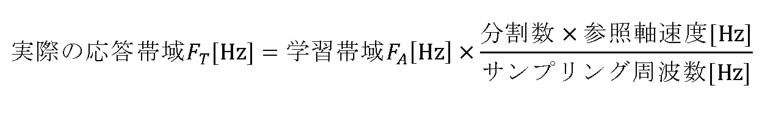
学習制御での実際の処理経路は、分割数切換部121で設定された分割数で、時間-位置変換器118が位置偏差の時間-位置変換(時間領域から位置領域への変換)を行い、帯域制限フィルタ112がカットオフ周波数FAで帯域制限を行い、分割数切換部121で設定された分割数で、位置-時間変換器119が、帯域制限された位置偏差の位置-時間変換(位置領域から時間領域への変換)を行う。位置-時間変換された位置偏差は、帯域制限フィルタによって数式3(以下の数3)で示されるカットオフ周波数FTで帯域制限を行われたことになる。カットオフ周波数FTが実際の応答帯域となる。
次に、学習制御部110Aの動作についてフローチャートを用いて説明する。
図17は、学習制御部110Aの動作を示すフローチャートである。
図17は、学習制御部110Aの動作を示すフローチャートである。
ステップS21において、動作パターン切換検出部116は、動作パターンの切り換えを検出する。そして、動作パターン切換検出部116は、切り換わった動作パターンが第1の動作パターンP1か第2の動作パターンP2を示す信号を分割数切換部121に出力する。
ステップS22において、分割数切換部121は、入力された信号に基づいて、切り換え後の第1の動作パターンP1又は第2の動作パターンP2に対応する、第1の分割数D1又は第2の分割数D2を分割数記憶部120から取得する。分割数記憶部120は、第1の動作パターンP1に対応する第1の分割数D1を第1の動作パターンP1に紐づけて記憶し、第2の動作パターンP2に対応する第2の分割数D2を第2の動作パターンP2に紐づけて記憶している。
ステップS23において、分割数切換部121は、時間-位置変換器118及び位置-時間変換器119の分割数を、取得した第1の分割数D1又は第2の分割数D2に切り換える。例えば、時間-位置変換器118及び位置-時間変換器119の分割数が第2の分割数D2に設定され、取得した分割数数が第1の分割数D1であった場合、分割数切換部121は、時間-位置変換器118及び位置-時間変換器119の分割数D2を第1の分割数D1に切り換える。
ステップS24において、加算器111、帯域制限フィルタ112、学習メモリ113、位置-時間変換器119及び動特性補償要素114は、学習制御を行って補正データを加算器102に出力する。
ステップS25において、学習制御部110Aは、処理を再度実行するかどうかを判断し、処理を実行する場合はステップS21に戻り、処理を実行しない場合は処理を終了する。
以上説明した動作の学習制御を、位置同期方式の学習制御という。
以上説明した動作の学習制御を、位置同期方式の学習制御という。
以上説明した第2の実施形態のサーボモータ装置によれば、動作パターンの異なる制御に対し、学習制御を安定化させる効果がある。そして、第2の実施形態のサーボモータ装置によれば、時間-位置変換器及び位置-時間変換器の分割数が、動作パターンによって、自動的に切り換わるので、時間-位置変換器及び位置-時間変換器の分割数の設定を手動で切りかえる手間が省け、現場の負担を軽減することができる効果がある。
(第3実施形態)
図18は本開示の第3の実施形態のサーボモータ制御装置の学習制御部の構成例を示すブロック図である。
本開示の第3の実施形態のサーボモータ制御装置は、図2に示した学習制御部110が図18に示す学習制御部110Bに置き換わっている。本実施形態のサーボモータ制御装置のサーボモータ制御部の構成は、第1の実施形態のサーボモータ制御部100と同じである。
図18は本開示の第3の実施形態のサーボモータ制御装置の学習制御部の構成例を示すブロック図である。
本開示の第3の実施形態のサーボモータ制御装置は、図2に示した学習制御部110が図18に示す学習制御部110Bに置き換わっている。本実施形態のサーボモータ制御装置のサーボモータ制御部の構成は、第1の実施形態のサーボモータ制御部100と同じである。
学習制御部110Bは、第1の実施形態の学習制御部110に、第2の実施形態の学習制御部110Aの学習制御器200の時間-位置変換器118及び位置-時間変換器119が加えられた構成となっている。加算器111、帯域制限フィルタ112、学習メモリ113、動特性補償要素114、時間-位置変換器118、及び位置-時間変換器119は学習制御器200A(図18において不図示)を構成する。
第3の実施形態では、時間-位置変換器118及び位置-時間変換器119の分割数は、動作パターン切換検出部116、分割数記憶部120及び分割数切換部121により、動作パターンの切り換わりに対応して切り換わる構成となっていた。本実施形態では、分割数が一つ、時間-位置変換器118及び位置-時間変換器119に設定される。
時間-位置変換器118及び位置-時間変換器119の動作は、第2の実施形態において説明したので、本実施形態では説明を省略する。
時間-位置変換器118及び位置-時間変換器119の動作は、第2の実施形態において説明したので、本実施形態では説明を省略する。
第3の実施形態のサーボモータ装置によれば、動作パターンの異なる制御に対し、学習制御を安定化させる効果がある。そして、第3の実施形態のサーボモータ装置によれば、第1の実施形態のサーボモータ装置の効果に加えて、分割数が一つの場合の、第2の実施形態のサーボモータ装置の位置同期方式の学習制御の適用が可能となる効果がある。
(第4実施形態)
本実施形態では、第1の実施形態の、帯域制限フィルタのカットオフ周波数を動作パターンによって切り換える制御と、第2の実施形態の、時間-位置変換器及び位置-時間変換器の分割数を動作パターンによって切り換える制御とを組み合わせた例について説明する。
本実施形態では、第1の実施形態の、帯域制限フィルタのカットオフ周波数を動作パターンによって切り換える制御と、第2の実施形態の、時間-位置変換器及び位置-時間変換器の分割数を動作パターンによって切り換える制御とを組み合わせた例について説明する。
図19は本開示の第4の実施形態のサーボモータ制御装置の学習制御部の構成例を示すブロック図である。
本開示の第4の実施形態のサーボモータ制御装置は、図2に示した学習制御部110が図19に示す学習制御部110Cに置き換わっている。本実施形態のサーボモータ制御装置のサーボモータ制御部の構成は、第1の実施形態のサーボモータ制御部100と同じである。
本開示の第4の実施形態のサーボモータ制御装置は、図2に示した学習制御部110が図19に示す学習制御部110Cに置き換わっている。本実施形態のサーボモータ制御装置のサーボモータ制御部の構成は、第1の実施形態のサーボモータ制御部100と同じである。
学習制御部110Cは、学習制御部110に、図12に示した学習制御部110Aの学習制御器200の時間-位置変換器118、位置-時間変換器119、分割数記憶部120及び分割数切換部121が加えられた構成となっている。加算器111、帯域制限フィルタ112、学習メモリ113、動特性補償要素114、時間-位置変換器118、及び位置-時間変換器119は学習制御器200A(図19において不図示)を構成する。
本実施形態では、動作パターン切換検出部116は、カットオフ周波数切換部117と分割数切換部121に接続され、動作パターンの切り換えを検出して、切り換わった動作パターンを示す信号をカットオフ周波数切換部117と分割数切換部121に出力する。
カットオフ周波数切換部117は、動作パターン切換検出部116から出力される信号で示される動作パターンに対応するカットオフ周波数をカットオフ周波数記憶部115から取得して、帯域制限フィルタ112のカットオフ周波数を、取得したカットオフ周波数に切り換える。
分割数切換部121は、動作パターン切換検出部116から出力される信号で示される動作パターンに対応する分割数を分割数記憶部120から取得して、時間-位置変換器118及び位置-時間変換器119の分割数を、取得した分割数に切り換える。
本実施形態では、数式1で示される学習帯域は、カットオフ周波数切換部117で設定されるカットオフ周波数となり、数式1で示される分割数は、分割数切換部121で設定される分割数となる。
第4の実施形態のサーボモータ装置によれば、動作パターンの異なる制御に対し、学習制御を安定化させる効果がある。そして、第4の実施形態のサーボモータ装置によれば、第1の実施形態のサーボモータ装置の効果に加えて、時間-位置変換器及び位置-時間変換器の分割数が、動作パターンによって、自動的に切り換わるので、時間-位置変換器及び位置-時間変換器の分割数の設定を手動で切りかえる手間が省け、現場の負担を軽減することができる効果がある。
(第5実施形態)
本実施形態では、帯域制限フィルタ112のカットオフ周波数を動作パターンの動作周波数に基づいて設定する例について説明する。
本実施形態では、帯域制限フィルタ112のカットオフ周波数を動作パターンの動作周波数に基づいて設定する例について説明する。
図20は本開示の第5の実施形態のサーボモータ制御装置の学習制御部の構成例を示すブロック図である。本開示の第5の実施形態のサーボモータ制御装置は、図18に示した学習制御部110Bが図20に示す学習制御部110Dに置き換わっている。本実施形態のサーボモータ制御装置のサーボモータ制御部の構成は、第1の実施形態のサーボモータ制御部100と同じである。
学習制御部110Dは、学習制御部110Bのカットオフ周波数記憶部115、動作パターン切換検出部116及びカットオフ周波数切換部117が削除され、学習制御部110Bに、動作周波数取得部122、倍率設定部123、及びカットオフ周波数設定部124が加えられた構成となっている。
動作周波数取得部122は、加工プログラムのGコード、又は数値制御装置から出力された信号に基づいて、動作周波数を取得したカットオフ周波数設定部124に出力する。
倍率設定部123は、動作周波数に掛ける倍率を設定して、カットオフ周波数設定部124に出力する。倍率は1以上に設定される。
カットオフ周波数設定部124は、動作周波数に倍率を掛けてカットオフ周波数を求め、帯域制限フィルタ112のカットオフ周波数を設定する。
カットオフ周波数設定部124は、動作周波数に倍率を掛けてカットオフ周波数を求め、帯域制限フィルタ112のカットオフ周波数を設定する。
第5の実施形態のサーボモータ装置によれば、動作周波数の異なる制御に対し、学習制御を安定化させる効果がある。そして、第5の実施形態のサーボモータ装置によれば、帯域制限フィルタのカットオフ周波数が、動作周波数によって自動的に切り換わるので、帯域制限フィルタのカットオフ周波数の設定を手動で切りかえる手間が省け、現場の負担を軽減することができる効果がある。
以上、各実施形態における、サーボモータ制御装置に含まれる機能ブロックを実現するために、サーボモータ制御装置は、ハードウェア、ソフトウェア又はこれらの組み合わせにより実現することができる。ここで、ソフトウェアによって実現されるとは、コンピュータがプログラムを読み込んで実行することにより実現されることを意味する。
本実施形態における、サーボモータ制御装置に含まれる機能ブロックをソフトウェア又はこれらの組み合わせにより実現する実現するために、具体的には、サーボモータ制御装置はそれぞれ、CPU(Central Processing Unit)等の演算処理装置を備える。また、サーボモータ制御装置は、演算処理装置がプログラムを実行する上で一時的に必要とされるデータを格納するためのRAM(Random Access Memory)等の主記憶装置も備える。
そして、各実施形態を含む本開示のサーボモータ制御装置によれば、動作パターン又は動作周波数の異なる制御に対し、学習制御を安定化させることができる。
上述した各実施形態は、本発明の好適な実施形態ではあるが、上記実施形態のみに本発明の範囲を限定するものではなく、本発明の要旨を逸脱しない範囲において種々の変更を施した形態での実施が可能である。
例えば、第5の実施形態は第2の実施形態に適用してもよく、その場合、図12に示した帯域制限フィルタ112は、図20に示した動作周波数取得部122、倍率設定部123、及びカットオフ周波数設定部124によって、カットオフ周波数が設定される。
例えば、第5の実施形態は第2の実施形態に適用してもよく、その場合、図12に示した帯域制限フィルタ112は、図20に示した動作周波数取得部122、倍率設定部123、及びカットオフ周波数設定部124によって、カットオフ周波数が設定される。
上記実施形態に関し、さらに以下の付記を開示する。
(付記1)
送り軸を複数の周期的な動作パターンでサーボモータ(107)を駆動するサーボモータ制御部(100)と、該サーボモータ制御部の位置偏差を補正する学習制御部(110、110B)とを備えたサーボモータ制御装置(10)であって、
前記学習制御部(110、110B)は、
動作パターンにおける位置偏差の高周波成分を帯域制限フィルタ(112)により減衰させて作成した補正データを、学習メモリ(113)に記憶し、位置偏差を補正する学習制御器(200、200A)と、
前記帯域制限フィルタの複数のカットオフ周波数を記憶するカットオフ周波数記憶部(115)と、
複数の動作パターンのどれが実行中かを判別し、動作パターンの切り換わりを検出する動作パターン切換検出部(116)と、
前記動作パターン切換検出部で動作パターンの切り替わりを検出した場合に、切り換えられた動作パターンに応じたカットオフ周波数を前記カットオフ周波数記憶部から取得して、前記帯域制限フィルタのカットオフ周波数を、取得したカットオフ周波数に切り換えるカットオフ周波数切換部(117)と、
を備える、サーボモータ制御装置。
(付記2)
前記学習制御器(200A)は、動作パターンにおけるサンプリング周期毎の位置偏差から、サンプリング周期における位置の範囲を複数の領域に分割した分割位置での位置偏差に変換し、変換した位置偏差の高周波成分を前記帯域制限フィルタにより減衰させ作成した補正データを、前記学習メモリに記憶し、分割位置に対応する補正データからサンプリング周期毎の補正データに変換し、位置偏差を補正する、付記1に記載のサーボモータ制御装置。
前記学習制御器(200A)は、動作パターンにおけるサンプリング周期毎の位置偏差から、サンプリング周期における位置の範囲を複数の領域に分割した分割位置での位置偏差に変換し、変換した位置偏差の高周波成分を前記帯域制限フィルタにより減衰させ作成した補正データを、前記学習メモリに記憶し、分割位置に対応する補正データからサンプリング周期毎の補正データに変換し、位置偏差を補正する、付記1に記載のサーボモータ制御装置。
(付記3)
送り軸を複数の周期的な動作パターンでサーボモータ(107)を駆動するサーボモータ制御部(100)と、該サーボモータ制御部の位置偏差を補正する学習制御部(110A、110C)とを備えたサーボモータ制御装置(10)であって、
前記学習制御部(110A、110C)は、
動作パターンにおけるサンプリング周期毎の位置偏差から、サンプリング周期における位置の範囲を複数の領域に分割した分割位置での位置偏差に変換し、変換された位置偏差に基づいて作成した補正データを、学習メモリ(113)に記憶し、分割位置に対応する補正データからサンプリング周期毎の補正データに変換し、位置偏差を補正する学習制御器(200A)と、
サンプリング周期における位置の範囲を複数の領域に分割する分割数を複数記憶する分割数記憶部(120)と、
複数の動作パターンのどれが実行中かを判別し、動作パターンの切り換わりを検出する動作パターン切換検出部(116)と、
前記動作パターン切換検出部で動作パターンの切り替わりを検出した場合に、切り換えられた動作パターンに応じた分割数を前記分割数記憶部から取得して、前記学習制御部で分割を行う分割数を取得した分割数に切り換える分割数切換部(121)と、
を備える、サーボモータ制御装置。
(付記4)
前記学習制御器(200A)は、動作パターンにおける位置偏差の高周波成分を減衰させる帯域制限フィルタ(112)を備え、前記学習メモリ(113)に記憶する補正データは前記帯域制限フィルタにより高周波成分を減衰させて作成した補正データであり、
前記帯域制限フィルタの複数のカットオフ周波数を記憶するカットオフ周波数記憶部(115)と、
前記動作パターン切換検出部(116)で動作パターンの切り替わりを検出した場合に、切り換えられた動作パターンに応じたカットオフ周波数を前記カットオフ周波数記憶部から取得して、前記帯域制限フィルタのカットオフ周波数を、取得したカットオフ周波数に切り換えるカットオフ周波数切換部(117)と、
を備える、付記3に記載のサーボモータ制御装置。
(付記5)
送り軸を複数の周期的な動作パターンでサーボモータ(107)を駆動するサーボモータ制御部(100)と、該サーボモータ制御部の位置偏差を補正する学習制御部(110D)とを備えたサーボモータ制御装置(10)であって、
前記学習制御部(110D)は、
動作パターンにおける位置偏差の高周波成分を帯域制限フィルタ(112)により減衰させて作成した補正データを、学習メモリ(113)に記憶し、位置偏差を補正する学習制御器(200、200A)と、
動作パターンの動作周波数を取得する動作周波数取得部(122)と、
前記動作周波数の倍率を設定する倍率設定部(123)と、
前記帯域制限フィルタのカットオフ周波数を、前記動作周波数に前記倍率を掛けて得られるカットオフ周波数に設定するカットオフ周波数設定部(124)と、
を備える、サーボモータ制御装置。
(付記6)
前記動作パターン切換検出部(116)は、加工プログラムにより動作パターンの切り換わりを検出する、付記1から4のいずれかに記載のサーボモータ制御装置。
前記動作パターン切換検出部(116)は、加工プログラムにより動作パターンの切り換わりを検出する、付記1から4のいずれかに記載のサーボモータ制御装置。
(付記7)
前記動作パターン切換検出部(116)は、信号により動作パターンの切り換わりを検出する、付記1から4のいずれかに記載のサーボモータ制御装置。
前記動作パターン切換検出部(116)は、信号により動作パターンの切り換わりを検出する、付記1から4のいずれかに記載のサーボモータ制御装置。
10 サーボモータ制御装置
100 サーボモータ制御部
101 減算器
102 加算器
103 位置制御部
104 減算器
105 速度制御部
106 電流制御部
107 サーボモータ
108 積分器
110、110A、110B、110C、110D 学習制御部
111 加算器
112 帯域制限フィルタ
113 学習メモリ
114 動特性補償要素
115 カットオフ周波数記憶部
116 動作パターン切換検出部
117 カットオフ周波数切換部
118 時間-位置変換器
119 位置-時間変換器
120 分割数記憶部
121 分割数切換部
200、200A 学習制御器
100 サーボモータ制御部
101 減算器
102 加算器
103 位置制御部
104 減算器
105 速度制御部
106 電流制御部
107 サーボモータ
108 積分器
110、110A、110B、110C、110D 学習制御部
111 加算器
112 帯域制限フィルタ
113 学習メモリ
114 動特性補償要素
115 カットオフ周波数記憶部
116 動作パターン切換検出部
117 カットオフ周波数切換部
118 時間-位置変換器
119 位置-時間変換器
120 分割数記憶部
121 分割数切換部
200、200A 学習制御器
Claims (7)
- 送り軸を複数の周期的な動作パターンでサーボモータを駆動するサーボモータ制御部と、該サーボモータ制御部の位置偏差を補正する学習制御部とを備えたサーボモータ制御装置であって、
前記学習制御部は、
動作パターンにおける位置偏差の高周波成分を帯域制限フィルタにより減衰させて作成した補正データを、学習メモリに記憶し、位置偏差を補正する学習制御器と、
前記帯域制限フィルタの複数のカットオフ周波数を記憶するカットオフ周波数記憶部と、
複数の動作パターンのどれが実行中かを判別し、動作パターンの切り換わりを検出する動作パターン切換検出部と、
前記動作パターン切換検出部で前記動作パターンの切り替わりを検出した場合に、切り換えられた動作パターンに応じたカットオフ周波数を前記カットオフ周波数記憶部から取得して、前記帯域制限フィルタのカットオフ周波数を、取得したカットオフ周波数に切り換えるカットオフ周波数切換部と、
を備える、サーボモータ制御装置。 - 前記学習制御器は、動作パターンにおけるサンプリング周期毎の位置偏差から、サンプリング周期における位置の範囲を複数の領域に分割した分割位置での位置偏差に変換し、変換した位置偏差の高周波成分を前記帯域制限フィルタにより減衰させ作成した補正データを、前記学習メモリに記憶し、分割位置に対応する補正データからサンプリング周期毎の補正データに変換し、位置偏差を補正する、請求項1に記載のサーボモータ制御装置。
- 送り軸を複数の周期的な動作パターンでサーボモータを駆動するサーボモータ制御部と、該サーボモータ制御部の位置偏差を補正する学習制御部とを備えたサーボモータ制御装置であって、
前記学習制御部は、
動作パターンにおけるサンプリング周期毎の位置偏差から、サンプリング周期における位置の範囲を複数の領域に分割した分割位置での位置偏差に変換し、変換した位置偏差に基づいて作成した補正データを、学習メモリに記憶し、分割位置に対応する補正データからサンプリング周期毎の補正データに変換し、位置偏差を補正する学習制御器と、
前記サンプリング周期における位置の範囲を前記複数の領域に分割する分割数を複数記憶する分割数記憶部と、
複数の動作パターンのどれが実行中かを判別し、動作パターンの切り換わりを検出する動作パターン切換検出部と、
前記動作パターン切換検出部で前記動作パターンの切り替わりを検出した場合に、切り換えられた動作パターンに応じた分割数を前記分割数記憶部から取得して、前記学習制御器で分割を行う分割数を取得した分割数に切り換える分割数切換部と、
を備える、サーボモータ制御装置。 - 前記学習制御器は、動作パターンにおける位置偏差の高周波成分を減衰させる帯域制限フィルタを備え、前記学習メモリに記憶する補正データは前記帯域制限フィルタにより高周波成分を減衰させて作成した補正データであり、
前記帯域制限フィルタの複数のカットオフ周波数を記憶するカットオフ周波数記憶部と、
前記動作パターン切換検出部で動作パターンの切り替わりを検出した場合に、切り換えられた動作パターンに応じたカットオフ周波数を前記カットオフ周波数記憶部から取得して、前記帯域制限フィルタのカットオフ周波数を、取得したカットオフ周波数に切り換えるカットオフ周波数切換部と、
を備える、請求項3に記載のサーボモータ制御装置。 - 送り軸を複数の周期的な動作パターンでサーボモータを駆動するサーボモータ制御部と、該サーボモータ制御部の位置偏差を補正する学習制御部とを備えたサーボモータ制御装置であって、
前記学習制御部は、
動作パターンにおける位置偏差の高周波成分を帯域制限フィルタにより減衰させて作成した補正データを、学習メモリに記憶し、位置偏差を補正する学習制御器と、
動作パターンの動作周波数を取得する動作周波数取得部と、
前記動作周波数の倍率を設定する倍率設定部と、
前記帯域制限フィルタのカットオフ周波数を、前記動作周波数に前記倍率を掛けて得られるカットオフ周波数に設定するカットオフ周波数設定部と、
を備える、サーボモータ制御装置。 - 前記動作パターン切換検出部は、加工プログラムにより動作パターンの切り換わりを検出する、請求項1から4のいずれかに記載のサーボモータ制御装置。
- 前記動作パターン切換検出部は、信号により動作パターンの切り換わりを検出する、請求項1から4のいずれかに記載のサーボモータ制御装置。
Priority Applications (1)
| Application Number | Priority Date | Filing Date | Title |
|---|---|---|---|
| PCT/JP2023/030135 WO2025041260A1 (ja) | 2023-08-22 | 2023-08-22 | サーボモータ制御装置 |
Applications Claiming Priority (1)
| Application Number | Priority Date | Filing Date | Title |
|---|---|---|---|
| PCT/JP2023/030135 WO2025041260A1 (ja) | 2023-08-22 | 2023-08-22 | サーボモータ制御装置 |
Publications (1)
| Publication Number | Publication Date |
|---|---|
| WO2025041260A1 true WO2025041260A1 (ja) | 2025-02-27 |
Family
ID=94731998
Family Applications (1)
| Application Number | Title | Priority Date | Filing Date |
|---|---|---|---|
| PCT/JP2023/030135 Pending WO2025041260A1 (ja) | 2023-08-22 | 2023-08-22 | サーボモータ制御装置 |
Country Status (1)
| Country | Link |
|---|---|
| WO (1) | WO2025041260A1 (ja) |
Citations (4)
| Publication number | Priority date | Publication date | Assignee | Title |
|---|---|---|---|---|
| JPH03235687A (ja) * | 1990-02-08 | 1991-10-21 | Mitsubishi Electric Corp | 外乱抑圧制御システム |
| JP2007233732A (ja) * | 2006-03-01 | 2007-09-13 | Ricoh Co Ltd | サーボ制御装置 |
| JP2011123616A (ja) * | 2009-12-09 | 2011-06-23 | Fanuc Ltd | 高速揺動動作を高精度化するサーボ制御システム |
| JP2018207695A (ja) * | 2017-06-06 | 2018-12-27 | ファナック株式会社 | サーボモータ制御装置 |
-
2023
- 2023-08-22 WO PCT/JP2023/030135 patent/WO2025041260A1/ja active Pending
Patent Citations (4)
| Publication number | Priority date | Publication date | Assignee | Title |
|---|---|---|---|---|
| JPH03235687A (ja) * | 1990-02-08 | 1991-10-21 | Mitsubishi Electric Corp | 外乱抑圧制御システム |
| JP2007233732A (ja) * | 2006-03-01 | 2007-09-13 | Ricoh Co Ltd | サーボ制御装置 |
| JP2011123616A (ja) * | 2009-12-09 | 2011-06-23 | Fanuc Ltd | 高速揺動動作を高精度化するサーボ制御システム |
| JP2018207695A (ja) * | 2017-06-06 | 2018-12-27 | ファナック株式会社 | サーボモータ制御装置 |
Similar Documents
| Publication | Publication Date | Title |
|---|---|---|
| JP4980453B2 (ja) | 加工を高精度化するサーボ制御システム | |
| US6859007B2 (en) | Servo motor drive control device | |
| US10286513B2 (en) | Control device for machine tool performing oscillation cutting | |
| US10434614B2 (en) | Control device for machine tool performing oscillation cutting | |
| US10471563B2 (en) | Control device for machine tool performing oscillation cutting | |
| JP6243260B2 (ja) | 主軸モータの制御装置 | |
| US10503140B2 (en) | Control device for machine tool performing oscillation cutting | |
| JP5815784B2 (ja) | 同期加工における同期誤差を低減するサーボ制御装置 | |
| WO2000039646A1 (en) | Numerical control device | |
| JPH0239304A (ja) | 数値制御工作機械における学習制御方式 | |
| JP2000250614A (ja) | バックラッシ補正装置および数値制御システム | |
| JP4226420B2 (ja) | 位置制御装置 | |
| WO2025041260A1 (ja) | サーボモータ制御装置 | |
| JP5246328B2 (ja) | モータ制御装置 | |
| CN115777087B (zh) | 机床的控制装置 | |
| JP6742943B2 (ja) | 工作機械送り系の制御装置 | |
| JP3427800B2 (ja) | 数値制御装置 | |
| WO2022025056A1 (ja) | 工作機械の制御装置 | |
| JP2019005832A (ja) | ロータリーシャー制御装置 | |
| CN119856388A (zh) | 电动机控制装置 | |
| JP2006073027A (ja) | 産業用機器制御方法および産業用機器 | |
| WO2026028284A1 (ja) | 制御装置 | |
| WO2025013209A1 (ja) | 制御装置、及びコンピュータ読み取り可能な記録媒体 | |
| JP2021122907A (ja) | ロボット制御装置、ロボットシステム及びロボット制御方法 | |
| WO2023067682A1 (ja) | サーボモータ制御装置 |
Legal Events
| Date | Code | Title | Description |
|---|---|---|---|
| 121 | Ep: the epo has been informed by wipo that ep was designated in this application |
Ref document number: 23949721 Country of ref document: EP Kind code of ref document: A1 |
|
| ENP | Entry into the national phase |
Ref document number: 2025541212 Country of ref document: JP Kind code of ref document: A |
|
| WWE | Wipo information: entry into national phase |
Ref document number: 2025541212 Country of ref document: JP |