WO2025041260A1 - Dispositif de commande de servomoteur - Google Patents
Dispositif de commande de servomoteur Download PDFInfo
- Publication number
- WO2025041260A1 WO2025041260A1 PCT/JP2023/030135 JP2023030135W WO2025041260A1 WO 2025041260 A1 WO2025041260 A1 WO 2025041260A1 JP 2023030135 W JP2023030135 W JP 2023030135W WO 2025041260 A1 WO2025041260 A1 WO 2025041260A1
- Authority
- WO
- WIPO (PCT)
- Prior art keywords
- servo motor
- operation pattern
- cutoff frequency
- learning
- control unit
- Prior art date
- Legal status (The legal status is an assumption and is not a legal conclusion. Google has not performed a legal analysis and makes no representation as to the accuracy of the status listed.)
- Pending
Links
Images


Classifications
-
- H—ELECTRICITY
- H02—GENERATION; CONVERSION OR DISTRIBUTION OF ELECTRIC POWER
- H02P—CONTROL OR REGULATION OF ELECTRIC MOTORS, ELECTRIC GENERATORS OR DYNAMO-ELECTRIC CONVERTERS; CONTROLLING TRANSFORMERS, REACTORS OR CHOKE COILS
- H02P29/00—Arrangements for regulating or controlling electric motors, appropriate for both AC and DC motors
- H02P29/20—Arrangements for regulating or controlling electric motors, appropriate for both AC and DC motors for controlling one motor used for different sequential operations
Definitions
- This disclosure relates to a servo motor control device that drives a servo motor with multiple periodic operation patterns for the feed axis.
- a servo motor control device used in a machine tool or industrial machine, when machining or the like is performed by commands of a periodic operating pattern, a servo motor control device that uses learning control to converge position deviation to near zero, thereby improving machining accuracy, is described in, for example, Patent Document 1.
- learning control may become unstable when multiple operations with different operation pattern bands are performed.
- a first representative aspect of the present disclosure is a servo motor control device including a servo motor control unit that drives a servo motor with a plurality of periodic operation patterns of a feed axis, and a learning control unit that corrects a position deviation of the servo motor control unit,
- the learning control unit is a learning controller which stores correction data generated by attenuating high frequency components of a position deviation in an operation pattern using a band limiting filter in a learning memory and corrects the position deviation; a cutoff frequency storage unit that stores a plurality of cutoff frequencies of the band limiting filter; an operation pattern switching detection unit that determines which of a plurality of operation patterns is being executed and detects switching of the operation pattern; a cutoff frequency switching unit that, when the operation pattern switching detection unit detects a switching of the operation pattern, acquires a cutoff frequency corresponding to the switched operation pattern from the cutoff frequency storage unit and switches the cutoff frequency of the band-limiting filter to the acquired cutoff frequency;
- the servo motor control device
- a second representative aspect of the present disclosure is a servo motor control device including a servo motor control unit that drives a servo motor with a plurality of periodic operation patterns of a feed axis, and a learning control unit that corrects a position deviation of the servo motor control unit,
- the learning control unit is a learning controller that converts a position deviation for each sampling period in the operation pattern into a position deviation at a divided position obtained by dividing a position range in the sampling period into a plurality of regions, stores compensation data created based on the converted position deviation in a learning memory, converts the compensation data corresponding to the divided positions into compensation data for each sampling period, and compensates for the position deviation; a division number storage unit configured to store a plurality of division numbers for dividing a position range in the sampling period into the plurality of regions; an operation pattern switching detection unit that determines which of a plurality of operation patterns is being executed and detects switching of the operation pattern; a division number switching unit that, when the operation pattern switching detection unit detects
- a third representative aspect of the present disclosure is a servo motor control device including a servo motor control unit that drives a servo motor with a plurality of periodic operation patterns of a feed axis, and a learning control unit that corrects a position deviation of the servo motor control unit,
- the learning control unit is a learning controller which stores correction data generated by attenuating high frequency components of a position deviation in an operation pattern using a band limiting filter in a learning memory and corrects the position deviation; an operating frequency acquisition unit for acquiring an operating frequency of the operating pattern; a magnification setting unit that sets a magnification of the operating frequency; a cutoff frequency setting unit that sets a cutoff frequency of the band-limiting filter to a cutoff frequency obtained by multiplying the operating frequency by the magnification;
- the servo motor control device includes:
- FIG. 1 is a block diagram showing an example of the overall configuration of a servo motor control device according to a first embodiment of the present disclosure
- 3 is a block diagram showing a configuration example of a learning control unit in the first embodiment.
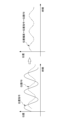
- FIG. 4A to 4C are diagrams showing waveforms of a position command and a position feedback, and a waveform diagram of a position deviation, when the position command is a repetitive command, in the first embodiment.
- 10A and 10B are diagrams illustrating how disturbances are removed by a band-limiting filter in a case where a position deviation includes high-frequency disturbances that are not synchronized with a position command in the first embodiment.
- FIGS. 4A to 4C are waveform diagrams showing a position deviation under normal control and a position deviation under learning control in the first embodiment, when a position command is a repetitive command.
- 4 is a diagram showing first and second operation patterns, bands required for the first and second operation patterns, and a cutoff frequency of a band-limiting filter in the first embodiment.
- FIG. FIG. 13 is a diagram for explaining eccentric turning.
- FIG. 1 illustrates a workpiece produced by eccentric turning.
- FIG. 4 is a waveform diagram showing X-axis and Y-axis movements of a tool in eccentric turning.
- FIG. 13 is a diagram for explaining normal turning and servo learning oscillation turning.
- 4 is a flowchart showing the operation of a learning control unit of the servo motor control device of the first embodiment.
- FIG. 13 is a block diagram showing an example configuration of a learning control unit of a servo motor control device according to a second embodiment of the present disclosure.
- FIG. FIG. 11 is an explanatory diagram of a process of converting a position deviation ⁇ obtained during sampling by a time-position converter into a position deviation at a predetermined reference position ⁇ (n) of a reference position ⁇ in the second embodiment.
- FIG. 11 is a waveform diagram showing how a time-position converter converts a position deviation that is a function of time into a position deviation that is a function of a reference axis position in the second embodiment.
- FIG. 11 is a waveform diagram for explaining the sampling period of the position deviation, which is a function of time, and the division number of the position deviation, which is a function of the reference axis position, in the time-position converter in the second embodiment.
- 11 is a waveform diagram of a position deviation showing the relationship between the conversion process of a time-position converter and a position-time converter, and the filtering process of a band-limiting filter.
- FIG. 10 is a flowchart showing the operation of a learning control unit of the servo motor control device of the second embodiment.
- FIG. 13 is a block diagram showing an example configuration of a learning control unit of a servo motor control device according to a third embodiment of the present disclosure.
- FIG. 13 is a block diagram showing an example configuration of a learning control unit of a servo motor control device according to a fourth embodiment of the present disclosure.
- FIG. 13 is a block diagram showing an example configuration of a learning control unit of a servo motor control device according to a fifth embodiment of the present disclosure.
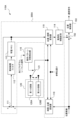
- Fig. 1 is a block diagram showing an example of the overall configuration of a servo motor control device according to a first embodiment of the present disclosure
- Fig. 2 is a block diagram showing an example of the configuration of a learning control unit.
- the servo motor control device 10 includes a servo motor control unit 100 and a learning control unit 110.
- the servo motor control unit 100 includes a subtractor 101, an adder 102, a position control unit 103, a subtractor 104, a speed control unit 105, a current control unit 106, a servo motor 107, and an integrator 108.
- the servo motor 107 is a motor with a rotating shaft or a linear motor.
- the object driven by the servo motor 107 is, for example, a mechanical part of a machine tool or industrial machine.
- the servo motor 107 may be provided as a part of the machine tool or industrial machine. In the following explanation, the case where the servo motor 107 is a motor with a rotating shaft will be explained.
- the learning control unit 110 includes an adder 111, a band-limiting filter 112, a learning memory 113, a dynamic characteristic compensation element 114, a cutoff frequency storage unit 115, an operation pattern switching detection unit 116, and a cutoff frequency switching unit 117.
- the adder 111, the band-limiting filter 112, the learning memory 113, and the dynamic characteristic compensation element 114 constitute a learning controller 200.
- FIG. 2 also shows the adder 102 and the position control unit 103 of the servo motor control unit 100.
- the learning control unit 110 may be provided as part of a machine tool, industrial machine, or the like, together with the servo motor control unit 100.
- the servo motor control unit 100 controls the operation of a machine tool or industrial machine by controlling the servo motor 107 based on a position command.
- the servo motor control unit 100 calculates the difference between the detected position detected by a position detector consisting of the servo motor 107 and integrator 108 and a position command input to the servo motor control unit 100 from a numerical control device or the like, and outputs this difference as a position deviation to the learning control unit 110.
- the servo motor control unit 100 adds the correction data output from the learning control unit 110 to the position deviation using the adder 102, and controls so that the position deviation converges to zero.
- the learning control unit 110 adds the correction data stored in the learning memory 113 to the input position deviation using an adder 111, band-limits the output from the adder 111 using a band-limiting filter 112, and stores the result as correction data in the learning memory 113.
- the learning control unit 110 stores correction data consisting of position deviation data in one pattern period of the same repeated command pattern in the learning memory 113, and in the next pattern period, outputs the correction data stored in the learning memory 113 to the adder 102 via the dynamic characteristic compensation element 114.
- the learning control unit 110 changes the cutoff frequency of the band-limiting filter 112 using a cutoff frequency storage unit 115, an operation pattern switch detection unit 116, and a cutoff frequency switch unit 117.
- the configurations and operations of the servo motor control unit 100 and the learning control unit 110 will be described in detail below.
- the speed control unit 105 performs PI control (Proportional-Integral Control), adds the integrated value of the speed deviation multiplied by integral gain K1v to the value of the speed deviation multiplied by proportional gain K2v, and outputs the result as a torque command to the current control unit 106.
- PI control Proportional-Integral Control
- PID control Proportional-Integral-Differential Control
- the current control unit 106 calculates the value of the current (current value) to be passed through the servo motor 107 based on the torque command, and controls the servo motor 107 based on this current value.
- the rotational speed of servo motor 107 is detected by a rotary encoder (not shown) provided on servo motor 107, and the detected speed is input to subtractor 104 as speed feedback.
- the detected position obtained by integrating the detected position in integrator 108 is input to subtractor 101 as position feedback (hereinafter referred to as position FB).
- position FB position feedback
- the rotary encoder serves as a speed detector, and the rotary encoder and integrator 108 serve as a position detector.
- the adder 111 shown in FIG. 2 adds the position deviation output from the servo motor control unit 100 and the correction data stored in the learning memory 113 , and outputs the sum to the band limiting filter 112 .
- the band-limiting filter 112 is a filter for stabilizing the learning control system, for example, a low-pass filter for cutting signals in the high-frequency range in a certain frequency domain, and stores the added value output from the adder 111 in the learning memory 113 as correction data.
- the position FB when the position command is a repetitive command, the position FB also has a repetitive waveform, and the position deviation, which is the difference between the position command and the position FB, also has a repetitive waveform synchronized with the position command.
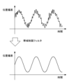
- the band-limiting filter 112 when the position deviation includes a high-frequency disturbance that is not synchronized with the position command, the band-limiting filter 112 removes this disturbance and extracts the component synchronized with the position command, thereby stabilizing the learning control.
- the learning memory 113 stores the correction data from one previous period that has been subjected to band limiting processing by the band limiting filter 112.
- the correction data stored in the learning memory 113 is output to the adder 111 and also to the dynamic characteristic compensation element 114.
- the dynamic characteristic compensation element 114 compensates for the phase delay and gain reduction of the controlled object using the correction data, and outputs the result to the adder 102.
- the adder 102 adds the position deviation and the correction data output from the dynamic characteristic compensation element 114 to the position deviation, and outputs the result to the position control unit 103.
- a cutoff frequency corresponding to a plurality of different operation patterns is stored in the cutoff frequency storage unit 115.
- the cutoff frequency is a frequency at which the gain characteristic of the Bode diagram is ⁇ 3 dB, or a frequency at which the phase characteristic is ⁇ 180 degrees.
- 2 shows an example in which the cutoff frequency storage unit 115 stores two cutoff frequencies as a plurality of cutoff frequencies. As shown in FIG. 2, the cutoff frequency storage unit 115 includes a cutoff frequency storage unit 114A (shown as a first cutoff frequency 114A in FIG.
- the motion pattern switching detection unit 116 detects switching of the motion pattern between the first motion pattern P1 and the second motion pattern P2, and outputs a signal indicating that the switched motion pattern is either the first motion pattern P1 or the second motion pattern P2 to the cutoff frequency switching unit 117.
- the motion pattern switching detection unit 116 detects the motion pattern based on, for example, the G code of the machining program or a signal output from a numerical control device. Note that when the two different motion patterns are eccentric turning and servo learning oscillation, as described below, eccentric turning and servo learning oscillation each have their own dedicated G code in the machining program.
- the motion pattern switching detection unit 116 can detect the motion pattern by the dedicated G code of the machining program.
- the cutoff frequency switching unit 117 acquires the cutoff frequency corresponding to the post-switching operation pattern from the cutoff frequency storage unit 115 based on the input signal, and switches the cutoff frequency of the band-limiting filter 112 to the acquired cutoff frequency. For example, when the cutoff frequency of the band-limiting filter 112 is set to the second cutoff frequency F2, the operation pattern switching detection unit 116 detects that the operation pattern has changed from the second operation pattern P2 to the first operation pattern P1. In this case, the operation pattern switching detection unit 116 outputs a signal indicating the first operation pattern P1 to the cutoff frequency switching unit 117.
- the cutoff frequency switching unit 117 acquires the first cutoff frequency F1 corresponding to the first operation pattern P1 from the cutoff frequency storage unit 115, and switches the cutoff frequency of the band-limiting filter 112 from the second cutoff frequency F2 to the first cutoff frequency F1.
- the cutoff frequency of the band-limiting filter is automatically switched depending on the operation pattern by the cutoff frequency memory unit 115, operation pattern switching detection unit 116, and cutoff frequency switching unit 117 described above.
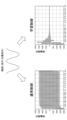
- FIG. 6 is a diagram showing the first and second operation patterns, the bands required for the first and second operation patterns, and the cutoff frequency of the band limiting filter 112.
- FIG. 6 is a diagram showing the first and second operation patterns, the bands required for the first and second operation patterns, and the cutoff frequency of the band limiting filter 112.
- the cutoff frequency of the band-limiting filter 112 is set to cutoff frequency F2.
- the servo motor control unit 100 operates in the band B2 required for the second operating pattern P2, as shown in FIG. 6, even if a disturbance of a frequency higher than the cutoff frequency F2 occurs, the disturbance is removed by the band-limiting filter 112.
- the servo motor control unit 100 operates in the band B1 required for the first operating pattern P1 if an asynchronous disturbance of a frequency higher than band B1 and lower than the cutoff frequency F2 occurs, the disturbance cannot be removed by the band-limiting filter 112 set to cutoff frequency F2. Therefore, the asynchronous disturbance causes the learning control of the learning controller 200 to become unstable.
- the servo motor control device 10 of the present embodiment aims to stabilize the learning control by switching the cutoff frequency in response to switching of the operation pattern.
- Two motion patterns requiring different bands include, for example, eccentric turning and servo learning oscillation in the case of machining motion patterns of a machine tool.
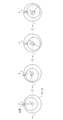
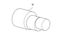
- Eccentric turning is a machining method in which one rotation of the workpiece (direction C in the figure) is synchronized with one circumference of the tool as shown in Fig. 7 to create a workpiece W shown in Fig. 8, which is offset from the center of the workpiece.
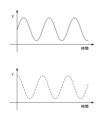
- the X-axis and Y-axis movements of the tool relative to the workpiece produce a repeating waveform as shown in the waveform diagram in Fig. 9, with the horizontal axis representing time.
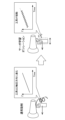
- Servo learning oscillation is a machining method in which the tool is oscillated in the feed direction during turning or drilling to shred the chips. For example, as shown in Figure 10, in normal turning, the tool advances at a constant speed in the Z direction, but in turning with servo learning oscillation, the tool advances by oscillating in the Z direction.
- the oscillation command is a command with a repeating pattern.
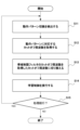
- FIG. 11 is a flowchart showing the operation of the learning control unit 110.
- the operation pattern switching detection unit 116 detects switching of the operation pattern and outputs a signal indicating that the switched operation pattern is the first operation pattern P1 or the second operation pattern P2 to the cutoff frequency switching unit 117.
- step S12 the cutoff frequency switching unit 117 acquires the first cutoff frequency F1 or the second cutoff frequency F2 corresponding to the first operation pattern P1 or the second operation pattern P2 after switching from the cutoff frequency memory unit 115 based on the input signal.
- the cutoff frequency memory unit 115 stores the first cutoff frequency F1 corresponding to the first operation pattern P1 in association with the first operation pattern P1, and stores the second cutoff frequency F2 corresponding to the second operation pattern P2 in association with the second operation pattern P2.
- the cutoff frequency switching unit 117 switches the cutoff frequency of the band-limiting filter 112 to the acquired cutoff frequency. For example, if the cutoff frequency of the band-limiting filter 112 is set to the second cutoff frequency F2 and the acquired cutoff frequency is the first cutoff frequency F1, the cutoff frequency switching unit 117 switches the cutoff frequency F2 of the band-limiting filter 112 to the first cutoff frequency F1.
- step S14 the adder 111, the band-limiting filter 112 switched to the acquired cutoff frequency, the learning memory 113, and the dynamic characteristic compensation element 114 perform learning control and output correction data to the adder 102.
- step S15 the learning control unit 110 determines whether to execute the process again, and if so, returns to step S11, and if not, ends the process.
- FIG. 13 is an explanatory diagram of the process of converting the position deviation ⁇ obtained during sampling by the time-position converter 118 into a position deviation at a predetermined reference position ⁇ (n) of the reference position ⁇ .
- the horizontal axis represents time (sampling time), and the upward direction of the vertical axis represents the reference position ⁇ . Also, the downward direction of the vertical axis represents the position deviation ⁇ .
- the position deviation obtained in the previous sampling period t(n-1) is ⁇ (n-1) and the reference position is ⁇ (n-1)
- the position deviation obtained in the current sampling period t(n) is ⁇ (n) and the reference position is ⁇ (n).
- the time-position converter 118 divides between the reference position ⁇ (n-1) and the reference position ⁇ (n) to obtain the reference position ⁇ (c), and interpolates the position deviation.
- FIG. 15 is a waveform diagram for explaining the sampling period of the position deviation, which is a function of time, and the division number of the position deviation, which is a function of the reference axis position, obtained by the time-position converter 118.
- the position error is sampled for each command generation period of the position command, that is, the sampling period of the position error is the same as the command generation period of the position command.
- the repetition period ⁇ of the position error after time-position conversion is 360°, as shown in FIG. 15, to match the sampling period of the position error to the scale of the division number, it is set to the division number calculated by Equation 2.
- the position-time converter 119 performs the reverse operation of the time-position converter 118. That is, the position-time converter 119 converts the position deviation (which becomes correction data) at a predetermined position ⁇ (n) in the reference position ⁇ into a position deviation ⁇ determined at a sampling period based on the input reference position ⁇ .
- the division numbers used in the conversion by the time-position converter 118 and the position-time converter 119 are set by the motion pattern switch detector 116 , the division number storage unit 120 and the division number switch unit 121 .
- the dynamic characteristic compensation element 114 compensates for the phase delay and gain reduction of the controlled object for the position deviation (correction data) that has been subjected to position-time conversion, and outputs the result to the adder 102.
- the adder 102 adds the position deviation and the correction data output from the dynamic characteristic compensation element 114 to the position deviation, and outputs the result to the position control unit 103.
- the division number storage unit 120 stores a number of division numbers corresponding to a number of different movement patterns.
- FIG. 12 shows an example in which the division number storage unit 120 includes a first division number storage unit 120A (shown as a first division number 1204A in FIG. 12) that stores a first division number D1 corresponding to a first movement pattern P1 in association with the first movement pattern P1, and a second division number storage unit 120B (shown as a second division number 1204B in FIG. 12) that stores a second division number D2 corresponding to a second movement pattern P2 in association with the second movement pattern P2, for two different movement patterns.
- a first division number storage unit 120A shown as a first division number 1204A in FIG. 12
- a second division number storage unit 120B shown as a second division number 1204B in FIG. 12
- the division number switching unit 121 obtains from the division number memory unit 120 the division number corresponding to the movement pattern output from the movement pattern switching detection unit 116, and switches the division numbers of the time-position converter 118 and the position-time converter 119 to the obtained division number. For example, when the division number of the time-position converter 118 and the position-time converter 119 is set to the second division number D2, the movement pattern switching detection unit 116 detects that the movement pattern has changed from the second movement pattern P2 to the first movement pattern P1. In this case, the movement pattern switching detection unit 116 outputs a signal indicating the first movement pattern P1 to the division number switching unit 121.
- the division number switching unit 121 acquires the first division number D1 corresponding to the first operation pattern P1 from the division number storage unit 120 based on a signal indicating the first operation pattern P1, and switches the division number of the time-position converter 118 and the position-time converter 119 from the second division number D2 to the first division number D1.
- the number of divisions of the time-position converter 118 and the position-time converter 119 are automatically switched depending on the operation pattern by the operation pattern switching detection unit 116, the division number storage unit 120, and the division number switching unit 121.
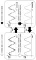
- FIG. 16 is a waveform diagram of the position deviation showing the relationship between the conversion process of the time-position converter 118 and the position-time converter 119 and the filtering process of the band-limiting filter 112.
- the position deviation before being band-limited by the band-limiting filter contains components with frequencies higher than the sampling period, and the position deviation after being band-limited by the band-limiting filter has had the high-frequency components removed.
- the black arrows indicate the actual processing paths in learning control
- the white arrows indicate the apparent processing paths converted into the time domain.
- the time-position converter 118 performs time-position conversion (conversion from the time domain to the position domain) of the position deviation using the division number set by the division number switching unit 121
- the band limiting filter 112 performs band limitation at the cutoff frequency F A
- the position-time converter 119 performs position-time conversion (conversion from the position domain to the time domain) of the band-limited position deviation using the division number set by the division number switching unit 121.
- the position-time converted position deviation is band-limited by the band limiting filter at the cutoff frequency F T shown in Equation 3 (Equation 3 below).
- the cutoff frequency F T becomes the actual response band.
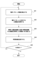
- FIG. 17 is a flowchart showing the operation of the learning control unit 110A.
- step S21 the operation pattern switching detection unit 116 detects a switch in the operation pattern. Then, the operation pattern switching detection unit 116 outputs a signal indicating that the switched operation pattern is the first operation pattern P1 or the second operation pattern P2 to the division number switching unit 121.
- step S22 the division number switching unit 121 acquires the first division number D1 or the second division number D2 corresponding to the first operation pattern P1 or the second operation pattern P2 after switching from the division number storage unit 120 based on the input signal.
- the division number storage unit 120 stores the first division number D1 corresponding to the first operation pattern P1 in association with the first operation pattern P1, and stores the second division number D2 corresponding to the second operation pattern P2 in association with the second operation pattern P2.
- step S23 the division number switching unit 121 switches the division numbers of the time-position converter 118 and the position-time converter 119 to the acquired first division number D1 or second division number D2. For example, if the division numbers of the time-position converter 118 and the position-time converter 119 are set to the second division number D2 and the acquired division number is the first division number D1, the division number switching unit 121 switches the division number D2 of the time-position converter 118 and the position-time converter 119 to the first division number D1.
- step S24 the adder 111, the band-limiting filter 112, the learning memory 113, the position-time converter 119, and the dynamic characteristic compensation element 114 perform learning control and output correction data to the adder 102.
- step S25 the learning control unit 110A determines whether or not to execute the process again, and if the process is to be executed again, the process returns to step S21, and if the process is not to be executed again, the process ends.
- the learning control of the operation described above is called position synchronous learning control.
- the servo motor device of the second embodiment described above has the effect of stabilizing learning control for controls with different operating patterns. Furthermore, the servo motor device of the second embodiment has the effect of automatically switching the division numbers of the time-position converter and the position-time converter depending on the operating pattern, eliminating the need to manually switch the settings of the division numbers of the time-position converter and the position-time converter, thereby reducing the burden on the site.
- FIG. 18 is a block diagram showing an example configuration of a learning control unit of a servo motor control device according to a third embodiment of the present disclosure.
- the learning control unit 110 shown in Fig. 2 is replaced with a learning control unit 110B shown in Fig. 18.
- the configuration of the servo motor control unit of the servo motor control device according to this embodiment is the same as that of the servo motor control unit 100 according to the first embodiment.
- the learning control unit 110B has a configuration in which the time-position converter 118 and the position-time converter 119 of the learning controller 200 of the learning control unit 110A of the second embodiment are added to the learning control unit 110 of the first embodiment.
- the adder 111, the band-limiting filter 112, the learning memory 113, the dynamic characteristic compensation element 114, the time-position converter 118, and the position-time converter 119 constitute the learning controller 200A (not shown in FIG. 18).
- the number of divisions of the time-position converter 118 and the position-time converter 119 is configured to be switched in response to switching of the movement pattern by the movement pattern switching detection unit 116, the number of divisions storage unit 120, and the number of divisions switching unit 121.
- the number of divisions is set to one in the time-position converter 118 and the position-time converter 119.
- the operations of the time-position converter 118 and the position-time converter 119 have been described in the second embodiment, and therefore will not be described in this embodiment.
- the servo motor device of the third embodiment has the effect of stabilizing learning control for control with different operating patterns. And, in addition to the effect of the servo motor device of the first embodiment, the servo motor device of the third embodiment has the effect of making it possible to apply the learning control of the position synchronization method of the servo motor device of the second embodiment when the division number is one.
- FIG. 19 is a block diagram showing an example configuration of a learning control unit of a servo motor control device according to a fourth embodiment of the present disclosure.
- the learning control unit 110 shown in Fig. 2 is replaced with a learning control unit 110C shown in Fig. 19.
- the configuration of the servo motor control unit of the servo motor control device according to this embodiment is the same as that of the servo motor control unit 100 according to the first embodiment.
- the learning control unit 110C is configured by adding to the learning control unit 110 the time-position converter 118, position-time converter 119, division number storage unit 120, and division number switching unit 121 of the learning controller 200 of the learning control unit 110A shown in FIG. 12.
- the adder 111, band-limiting filter 112, learning memory 113, dynamic characteristic compensation element 114, time-position converter 118, and position-time converter 119 constitute the learning controller 200A (not shown in FIG. 19).
- the operation pattern switching detection unit 116 is connected to the cutoff frequency switching unit 117 and the division number switching unit 121, detects switching of the operation pattern, and outputs a signal indicating the switched operation pattern to the cutoff frequency switching unit 117 and the division number switching unit 121.
- the cutoff frequency switching unit 117 acquires the cutoff frequency corresponding to the operation pattern indicated by the signal output from the operation pattern switching detection unit 116 from the cutoff frequency memory unit 115, and switches the cutoff frequency of the band-limiting filter 112 to the acquired cutoff frequency.
- the division number switching unit 121 obtains the division number corresponding to the movement pattern indicated by the signal output from the movement pattern switching detection unit 116 from the division number storage unit 120, and switches the division numbers of the time-position converter 118 and the position-time converter 119 to the obtained division number.
- the learning band shown in formula 1 is the cutoff frequency set by the cutoff frequency switching unit 117
- the division number shown in formula 1 is the division number set by the division number switching unit 121.
- the servo motor device of the fourth embodiment has the effect of stabilizing learning control for control with different operating patterns. And, in addition to the effect of the servo motor device of the first embodiment, the servo motor device of the fourth embodiment has the effect of automatically switching the division numbers of the time-position converter and the position-time converter depending on the operating pattern, eliminating the need to manually switch the settings of the division numbers of the time-position converter and the position-time converter, thereby reducing the burden on the site.
- FIG. 20 is a block diagram showing an example configuration of a learning control unit of a servo motor control device according to a fifth embodiment of the present disclosure.
- the learning control unit 110B shown in FIG. 18 is replaced with a learning control unit 110D shown in FIG. 20.
- the configuration of the servo motor control unit of the servo motor control device according to this embodiment is the same as the servo motor control unit 100 according to the first embodiment.
- the learning control unit 110D has a configuration in which the cutoff frequency memory unit 115, the operation pattern switching detection unit 116, and the cutoff frequency switching unit 117 of the learning control unit 110B have been deleted, and an operation frequency acquisition unit 122, a magnification setting unit 123, and a cutoff frequency setting unit 124 have been added to the learning control unit 110B.
- the operating frequency acquisition unit 122 outputs the operating frequency to the cutoff frequency setting unit 124 based on the G code of the machining program or a signal output from the numerical control device.
- the magnification setting unit 123 sets a magnification by which the operating frequency is multiplied, and outputs the set magnification to the cutoff frequency setting unit 124.
- the magnification is set to 1 or more.
- the cutoff frequency setting unit 124 obtains the cutoff frequency by multiplying the operating frequency by a magnification factor, and sets the cutoff frequency of the band-limiting filter 112 .
- the servo motor device of the fifth embodiment has the effect of stabilizing learning control for controls with different operating frequencies. Furthermore, the servo motor device of the fifth embodiment has the effect of eliminating the need to manually change the cutoff frequency setting of the band-limiting filter, thereby reducing the burden on the site.
- the servo motor control device can be realized by hardware, software, or a combination of these.
- being realized by software means being realized by a computer reading and executing a program.
- each servo motor control device is equipped with an arithmetic processing device such as a CPU (Central Processing Unit).
- the servo motor control device also has a main storage device such as a RAM (Random Access Memory) for storing data temporarily required for the arithmetic processing device to execute a program.
- the servo motor control device disclosed herein, including each embodiment, can stabilize learning control for control with different operating patterns or operating frequencies.
- the scope of the present invention is not limited to only the above-described embodiments, and the present invention can be implemented in various modified forms without departing from the gist of the present invention.
- the fifth embodiment may be applied to the second embodiment.
- the cutoff frequency of the band-limiting filter 112 shown in FIG. 12 is set by the operating frequency acquisition unit 122, the magnification setting unit 123, and the cutoff frequency setting unit 124 shown in FIG. 20.
- a servo motor control device including a servo motor control unit (100) that drives a servo motor (107) with a plurality of periodic operation patterns for a feed axis, and a learning control unit (110, 110B) that corrects a position deviation of the servo motor control unit,
- the learning control unit (110, 110B) a learning controller (200, 200A) for storing correction data in a learning memory (113) by attenuating high frequency components of a position deviation in an operation pattern using a band limiting filter (112) and correcting the position deviation; a cutoff frequency storage unit (115) for storing a plurality of cutoff frequencies of the band limiting filter; an operation pattern switching detection unit (116) that determines which of a plurality of operation patterns is being executed and detects switching of the operation pattern; a cutoff frequency switching unit (117) that, when the operation pattern switching detection unit detects a switching of the operation pattern, acquires
- (Appendix 2) The servo motor control device according to claim 1, wherein the learning controller (200A) converts the position deviation for each sampling period in the operation pattern into position deviations at divided positions obtained by dividing the position range in the sampling period into a plurality of regions, attenuates high-frequency components of the converted position deviation using the band-limiting filter to create correction data, stores the created correction data in the learning memory, converts the correction data corresponding to the divided positions into correction data for each sampling period, and corrects the position deviation.
- the learning controller (200A) converts the position deviation for each sampling period in the operation pattern into position deviations at divided positions obtained by dividing the position range in the sampling period into a plurality of regions, attenuates high-frequency components of the converted position deviation using the band-limiting filter to create correction data, stores the created correction data in the learning memory, converts the correction data corresponding to the divided positions into correction data for each sampling period, and corrects the position deviation.
- a servo motor control device including a servo motor control unit (100) that drives a servo motor (107) with a plurality of periodic operation patterns for a feed axis, and a learning control unit (110A, 110C) that corrects a position deviation of the servo motor control unit,
- the learning control unit (110A, 110C) a learning controller (200A) that converts a position deviation for each sampling period in the operation pattern into a position deviation at a divided position obtained by dividing a position range in the sampling period into a plurality of regions, stores correction data created based on the converted position deviation in a learning memory (113), converts the correction data corresponding to the divided position into correction data for each sampling period, and corrects the position deviation;
- a division number storage unit 120) for storing a plurality of division numbers for dividing a position range in a sampling period into a plurality of regions; an operation pattern switching detection unit (116) that determines which of a plurality of operation patterns is being executed
- the learning controller (200A) includes a band-limiting filter (112) that attenuates high-frequency components of a position deviation in an operation pattern, and the correction data stored in the learning memory (113) is correction data created by attenuating high-frequency components using the band-limiting filter; a cutoff frequency storage unit (115) for storing a plurality of cutoff frequencies of the band limiting filter; a cutoff frequency switching unit (117) that, when the operation pattern switching detection unit (116) detects a switching of the operation pattern, acquires a cutoff frequency corresponding to the switched operation pattern from the cutoff frequency storage unit and switches the cutoff frequency of the band limiting filter to the acquired cutoff frequency; 4.
- the servo motor control device comprising:
- a servo motor control device including a servo motor control unit (100) that drives a servo motor (107) with a plurality of periodic operation patterns for a feed axis, and a learning control unit (110D) that corrects a position deviation of the servo motor control unit,
- the learning control unit (110D) a learning controller (200, 200A) for storing correction data in a learning memory (113) by attenuating high frequency components of a position deviation in an operation pattern using a band limiting filter (112) and correcting the position deviation;
- An operating frequency acquisition unit (122) for acquiring an operating frequency of an operating pattern;
- a magnification setting unit (123) that sets a magnification of the operating frequency;
- a cutoff frequency setting unit (124) that sets a cutoff frequency of the band limiting filter to a cutoff frequency obtained by multiplying the operating frequency by the magnification;
- a servo motor control device comprising:
- Servo motor control device 100 Servo motor control section 101 Subtractor 102 Adder 103 Position control section 104 Subtractor 105 Speed control section 106 Current control section 107 Servo motor 108 Integrator 110, 110A, 110B, 110C, 110D Learning control section 111 Adder 112 Band limiting filter 113 Learning memory 114 Dynamic characteristic compensation element 115 Cut-off frequency storage section 116 Operation pattern switching detection section 117 Cut-off frequency switching section 118 Time-position converter 119 Position-time converter 120 Division number storage section 121 Division number switching section 200, 200A Learning controller
Landscapes
- Engineering & Computer Science (AREA)
- Power Engineering (AREA)
- Control Of Electric Motors In General (AREA)
Abstract
La présente invention stabilise la commande d'apprentissage, par rapport à des commandes qui ont différents motifs opérationnels ou fréquences de fonctionnement. Ce dispositif de commande de servomoteur, qui entraîne un servomoteur avec une pluralité de motifs opérationnels périodiques autour d'un axe d'alimentation, est configuré de telle sorte que, en réponse à la commutation des motifs opérationnels, la fréquence de coupure d'un filtre de limitation de bande d'une unité de commande d'apprentissage pour corriger un écart de position est soit commutée vers une fréquence de coupure correspondant à un motif opérationnel ou réglée à une fréquence de coupure trouvée en multipliant la fréquence de fonctionnement du motif opérationnel par un facteur de mise à l'échelle prédéterminé. Une unité de commande d'apprentissage pour corriger des écarts de position, qui est une partie du dispositif de commande de servomoteur qui entraîne le servomoteur dans la pluralité de motifs opérationnels périodiques autour de l'axe d'alimentation, est configurée de telle sorte que, en réponse à la commutation du motif opérationnel, le nombre de divisions utilisées lors de la conversion entre l'écart de position à chacune des périodes d'échantillonnage et l'écart de position à une position dans une période d'échantillonnage est commuté vers un nombre de divisions correspondant au motif opérationnel.
Priority Applications (1)
| Application Number | Priority Date | Filing Date | Title |
|---|---|---|---|
| PCT/JP2023/030135 WO2025041260A1 (fr) | 2023-08-22 | 2023-08-22 | Dispositif de commande de servomoteur |
Applications Claiming Priority (1)
| Application Number | Priority Date | Filing Date | Title |
|---|---|---|---|
| PCT/JP2023/030135 WO2025041260A1 (fr) | 2023-08-22 | 2023-08-22 | Dispositif de commande de servomoteur |
Publications (1)
| Publication Number | Publication Date |
|---|---|
| WO2025041260A1 true WO2025041260A1 (fr) | 2025-02-27 |
Family
ID=94731998
Family Applications (1)
| Application Number | Title | Priority Date | Filing Date |
|---|---|---|---|
| PCT/JP2023/030135 Pending WO2025041260A1 (fr) | 2023-08-22 | 2023-08-22 | Dispositif de commande de servomoteur |
Country Status (1)
| Country | Link |
|---|---|
| WO (1) | WO2025041260A1 (fr) |
Citations (4)
| Publication number | Priority date | Publication date | Assignee | Title |
|---|---|---|---|---|
| JPH03235687A (ja) * | 1990-02-08 | 1991-10-21 | Mitsubishi Electric Corp | 外乱抑圧制御システム |
| JP2007233732A (ja) * | 2006-03-01 | 2007-09-13 | Ricoh Co Ltd | サーボ制御装置 |
| JP2011123616A (ja) * | 2009-12-09 | 2011-06-23 | Fanuc Ltd | 高速揺動動作を高精度化するサーボ制御システム |
| JP2018207695A (ja) * | 2017-06-06 | 2018-12-27 | ファナック株式会社 | サーボモータ制御装置 |
-
2023
- 2023-08-22 WO PCT/JP2023/030135 patent/WO2025041260A1/fr active Pending
Patent Citations (4)
| Publication number | Priority date | Publication date | Assignee | Title |
|---|---|---|---|---|
| JPH03235687A (ja) * | 1990-02-08 | 1991-10-21 | Mitsubishi Electric Corp | 外乱抑圧制御システム |
| JP2007233732A (ja) * | 2006-03-01 | 2007-09-13 | Ricoh Co Ltd | サーボ制御装置 |
| JP2011123616A (ja) * | 2009-12-09 | 2011-06-23 | Fanuc Ltd | 高速揺動動作を高精度化するサーボ制御システム |
| JP2018207695A (ja) * | 2017-06-06 | 2018-12-27 | ファナック株式会社 | サーボモータ制御装置 |
Similar Documents
| Publication | Publication Date | Title |
|---|---|---|
| JP4980453B2 (ja) | 加工を高精度化するサーボ制御システム | |
| US6859007B2 (en) | Servo motor drive control device | |
| US10286513B2 (en) | Control device for machine tool performing oscillation cutting | |
| US10434614B2 (en) | Control device for machine tool performing oscillation cutting | |
| US10471563B2 (en) | Control device for machine tool performing oscillation cutting | |
| JP6243260B2 (ja) | 主軸モータの制御装置 | |
| US10503140B2 (en) | Control device for machine tool performing oscillation cutting | |
| JP5815784B2 (ja) | 同期加工における同期誤差を低減するサーボ制御装置 | |
| WO2000039646A1 (fr) | Dispositif de commande numerique | |
| JPH0239304A (ja) | 数値制御工作機械における学習制御方式 | |
| JP2000250614A (ja) | バックラッシ補正装置および数値制御システム | |
| JP4226420B2 (ja) | 位置制御装置 | |
| WO2025041260A1 (fr) | Dispositif de commande de servomoteur | |
| JP5246328B2 (ja) | モータ制御装置 | |
| CN115777087B (zh) | 机床的控制装置 | |
| JP6742943B2 (ja) | 工作機械送り系の制御装置 | |
| JP3427800B2 (ja) | 数値制御装置 | |
| WO2022025056A1 (fr) | Dispositif de commande de machine-outil | |
| JP2019005832A (ja) | ロータリーシャー制御装置 | |
| CN119856388A (zh) | 电动机控制装置 | |
| JP2006073027A (ja) | 産業用機器制御方法および産業用機器 | |
| WO2026028284A1 (fr) | Dispositif de commande | |
| WO2025013209A1 (fr) | Dispositif de commande et support d'enregistrement lisible par ordinateur | |
| JP2021122907A (ja) | ロボット制御装置、ロボットシステム及びロボット制御方法 | |
| WO2023067682A1 (fr) | Dispositif de commande de servomoteur |
Legal Events
| Date | Code | Title | Description |
|---|---|---|---|
| 121 | Ep: the epo has been informed by wipo that ep was designated in this application |
Ref document number: 23949721 Country of ref document: EP Kind code of ref document: A1 |
|
| ENP | Entry into the national phase |
Ref document number: 2025541212 Country of ref document: JP Kind code of ref document: A |
|
| WWE | Wipo information: entry into national phase |
Ref document number: 2025541212 Country of ref document: JP |