WO2025018199A1 - 地熱発電システム - Google Patents
地熱発電システム Download PDFInfo
- Publication number
- WO2025018199A1 WO2025018199A1 PCT/JP2024/024562 JP2024024562W WO2025018199A1 WO 2025018199 A1 WO2025018199 A1 WO 2025018199A1 JP 2024024562 W JP2024024562 W JP 2024024562W WO 2025018199 A1 WO2025018199 A1 WO 2025018199A1
- Authority
- WO
- WIPO (PCT)
- Prior art keywords
- chemical
- power generation
- agent
- generation system
- geothermal
- Prior art date
- Legal status (The legal status is an assumption and is not a legal conclusion. Google has not performed a legal analysis and makes no representation as to the accuracy of the status listed.)
- Pending
Links
Images


Classifications
-
- F—MECHANICAL ENGINEERING; LIGHTING; HEATING; WEAPONS; BLASTING
- F03—MACHINES OR ENGINES FOR LIQUIDS; WIND, SPRING, OR WEIGHT MOTORS; PRODUCING MECHANICAL POWER OR A REACTIVE PROPULSIVE THRUST, NOT OTHERWISE PROVIDED FOR
- F03G—SPRING, WEIGHT, INERTIA OR LIKE MOTORS; MECHANICAL-POWER PRODUCING DEVICES OR MECHANISMS, NOT OTHERWISE PROVIDED FOR OR USING ENERGY SOURCES NOT OTHERWISE PROVIDED FOR
- F03G4/00—Devices for producing mechanical power from geothermal energy
- F03G4/069—Devices for producing mechanical power from geothermal energy characterised by the brine or scale treatment, e.g. brine desalination, scale deposit prevention or corrosion-proofing
-
- F—MECHANICAL ENGINEERING; LIGHTING; HEATING; WEAPONS; BLASTING
- F03—MACHINES OR ENGINES FOR LIQUIDS; WIND, SPRING, OR WEIGHT MOTORS; PRODUCING MECHANICAL POWER OR A REACTIVE PROPULSIVE THRUST, NOT OTHERWISE PROVIDED FOR
- F03G—SPRING, WEIGHT, INERTIA OR LIKE MOTORS; MECHANICAL-POWER PRODUCING DEVICES OR MECHANISMS, NOT OTHERWISE PROVIDED FOR OR USING ENERGY SOURCES NOT OTHERWISE PROVIDED FOR
- F03G4/00—Devices for producing mechanical power from geothermal energy
- F03G4/023—Devices for producing mechanical power from geothermal energy characterised by the geothermal collectors
- F03G4/029—Devices for producing mechanical power from geothermal energy characterised by the geothermal collectors closed loop geothermal collectors, i.e. the fluid is pumped through a closed loop in heat exchange with the geothermal source, e.g. via a heat exchanger
-
- F—MECHANICAL ENGINEERING; LIGHTING; HEATING; WEAPONS; BLASTING
- F03—MACHINES OR ENGINES FOR LIQUIDS; WIND, SPRING, OR WEIGHT MOTORS; PRODUCING MECHANICAL POWER OR A REACTIVE PROPULSIVE THRUST, NOT OTHERWISE PROVIDED FOR
- F03G—SPRING, WEIGHT, INERTIA OR LIKE MOTORS; MECHANICAL-POWER PRODUCING DEVICES OR MECHANISMS, NOT OTHERWISE PROVIDED FOR OR USING ENERGY SOURCES NOT OTHERWISE PROVIDED FOR
- F03G4/00—Devices for producing mechanical power from geothermal energy
- F03G4/072—Controlling or monitoring
-
- Y—GENERAL TAGGING OF NEW TECHNOLOGICAL DEVELOPMENTS; GENERAL TAGGING OF CROSS-SECTIONAL TECHNOLOGIES SPANNING OVER SEVERAL SECTIONS OF THE IPC; TECHNICAL SUBJECTS COVERED BY FORMER USPC CROSS-REFERENCE ART COLLECTIONS [XRACs] AND DIGESTS
- Y02—TECHNOLOGIES OR APPLICATIONS FOR MITIGATION OR ADAPTATION AGAINST CLIMATE CHANGE
- Y02E—REDUCTION OF GREENHOUSE GAS [GHG] EMISSIONS, RELATED TO ENERGY GENERATION, TRANSMISSION OR DISTRIBUTION
- Y02E10/00—Energy generation through renewable energy sources
- Y02E10/10—Geothermal energy
Definitions
- the present invention relates to a geothermal power generation system.
- Geothermal power generation systems extract high-temperature geothermal fluids (geothermal water and geothermal steam) from production wells and generate electricity using the geothermal water or geothermal steam separated from the geothermal fluid.
- Geothermal fluids extracted from production wells contain more calcium, dissolved silica, and other elements than well water or river water.
- the return lines are usually installed over long distances, and the cleaning agent supplied upstream of the return line becomes diluted as it moves downstream, resulting in insufficient cleaning of scale adhering to the downstream piping and resulting in poor cleaning.
- One aspect of the present invention provides a geothermal power generation system that can sufficiently remove scale from the reduction line.
- a geothermal power generation system comprises a gas-liquid separator that separates geothermal water and geothermal steam from geothermal fluid ejected from a production well, a power generation device that generates power using the geothermal water or the geothermal steam separated by the gas-liquid separator as a heat source, a retention tank that stores the geothermal water whose heat has been recovered by the power generation device, a reduction line that connects an outlet of the retention tank to a reduction well, a reduction pump that is provided midway along the reduction line and returns the geothermal water discharged from the retention tank to the reduction well, a chemical injection port provided on the reduction line between the retention tank and the reduction pump, a first chemical addition device that injects chemicals into the chemical injection port, and a second chemical addition device that supplies chemicals to the reduction well.
- the system is provided with a branching section that branches the flow of the geothermal water, a first liquid analyzer that is connected vertically upward from the branching section, a scale chip collector that is connected horizontally from the branching section and has a residue inlet, a dissolving agent inlet, and a residue outlet, a dissolving agent addition device that injects a dissolving agent into the dissolving agent inlet, and a control device that switches between injecting the dissolving agent by the first dissolving agent addition device and stopping injection of the dissolving agent by the dissolving agent addition device based on the analysis results of the first liquid analyzer.
- the geothermal power generation system can sufficiently remove scale from the reduction line.
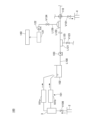
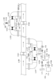
- FIG. 1 is a schematic configuration diagram of a geothermal power generation system according to one embodiment.
- 4 is a time chart showing a cleaning operation in a geothermal power generation system according to one embodiment.
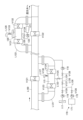
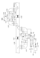
- FIG. 2 is a schematic configuration diagram showing another example of a geothermal power generation system according to an embodiment.
- FIG. 4 is an enlarged view of a main portion of FIG. 3 .
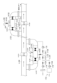
- FIG. 4 is an enlarged view (part 1) of a main portion of FIG. 3 for explaining a cleaning operation in another example of a geothermal power generation system according to an embodiment.
- FIG. 4 is an enlarged view (part 2) of a main portion of FIG. 3 for explaining a cleaning operation in another example of a geothermal power generation system according to an embodiment.
- FIG. 5 is an enlarged view (part 3) of a main portion of FIG. 3 for explaining a cleaning operation in another example of a geothermal power generation system according to an embodiment.
- FIG. 4 is an enlarged view (part 4) of a main portion of FIG. 3 for explaining a cleaning operation in another example of a geothermal power generation system according to an embodiment.
- geothermal power generation system 100 will be described when normal operation (power generation) is stopped and the reduction line L100 is cleaned.
- the geothermal steam separated in the gas-liquid separator 3 is sent to a flash power generation system 101a, which generates electricity using the geothermal steam separated in the gas-liquid separator 3 as a heat source, and the geothermal water separated in the gas-liquid separator 3 is sent to a binary power generation system 101b, which generates electricity using the geothermal water separated in the gas-liquid separator 3 as a heat source.
- the flash power generation system 101a has a turbine that rotates by being supplied with geothermal steam separated in the gas-liquid separator 3, a generator connected to the turbine, a condenser that condenses the geothermal steam discharged from the turbine, a cooling tower that cools the condensed water condensed in the condenser, etc.
- the binary power generation system 101b has a medium evaporator that evaporates a low-boiling point heat medium by heat exchange, a turbine that rotates by being supplied with the vaporized heat medium, a generator, a medium condenser, etc.
- the reduction line L100 is a line that connects the outlet of the retention tank 102 to the reduction well 4.
- the drug injection port 104 is provided in the reduction line L100 between the retention tank 102 and the reduction pump 103.
- the first chemical addition device 130 is a device that injects chemicals into the chemical injection port, and may have multiple chemical tanks 131a, 131b, 131c that store chemicals, and multiple chemical injection pumps 132a, 132b, 132c that are connected to the multiple chemical tanks 131a, 131b, 131c, respectively, and discharge the chemicals toward the chemical injection port 104.
- the number of chemical tanks 131a, 131b, 131c is three in the example shown in FIG. 1, but is not limited to this and may be selected according to the number of chemical types used, and may be four or more.
- the number of chemical injection pumps 132a, 132b, 132c may be selected according to the number of chemical tanks 131a, 131b, 131c.
- the multiple chemical tanks 131a, 131b, 131c may contain a tracer reagent, a cleaning agent, and a corrosive agent that is corrosive to the metals that make up the reduction line L100, respectively.
- the chemical tank 131a contains a tracer reagent
- the chemical tank 131b contains a cleaning agent
- the chemical tank 131c contains a corrosive agent.
- the chemical injection pump connected to the chemical tank 131a containing the tracer reagent may be referred to as the tracer reagent injection pump 132a
- the chemical injection pump connected to the chemical tank 131b containing the cleaning agent may be referred to as the cleaning agent injection pump 132b
- the chemical injection pump connected to the chemical tank 131c containing the corrosive agent may be referred to as the corrosive agent injection pump 132c.
- the tracer reagent is a chemical used to confirm that the cleaning agent has reached the downstream side of the reduction line L100.
- tracer reagents include halogens such as iodine and bromine, radioisotopes such as iodine-131, bromine-82, and tritium, aromatic sulfonates such as sodium benzoate, sodium toluenesulfonate, sodium xylenesulfonate, sodium benzenesulfonate, 1-naphthalenesulfonic acid, and 1,5-naphthalenedisulfonic acid, fluorescent dyes such as sodium fluorescein, rhodamine WT, and 2,6,8-naphthylamine disulfonic acid (amino G acid), metal indicators, and benzoic acid.
- the tracer reagent is an aromatic sulfonate.
- the cleaning agent is a chemical used to remove and clean scale adhering to the inside of the piping of the reduction line L100.
- the cleaning agent may be, for example, a chemical containing one or more selected from an acidic chemical, a basic chemical, a chelating agent, a hydrogen peroxide-based chemical, a dispersing agent, and a catalase-based chemical.
- Acidic agents can be used to dissolve calcium-based scale.
- acidic agents include sulfuric acid, hydrochloric acid, acetic acid, and citric acid.
- Basic agents can be used to dissolve silica-based scale (amorphous silica). Examples of basic agents include sodium hydroxide, potassium hydroxide, and ammonium salts.
- Chelating agents can be used to mask dissolved metals in geothermal water under pH adjustment before using other cleaning agents, thereby reducing the waste of other cleaning agents.
- chelating agents examples include ethylenediaminetetraacetic acid (EDTA), nitrilotriacetic acid (NTA), hydroxyethylenediaminetriacetic acid (HEDTA), diethylenetriaminepentaacetic acid (DTPA), trimethanolamine, and sodium gluconate.
- Hydrogen peroxide-based agents can be used to dissolve soft mud. Examples of hydrogen peroxide-based agents include hydrogen peroxide.
- Dispersing agents can be used to disperse and remove scale attached to the inner walls of pipes, etc. Examples of dispersants include sodium polyacrylate and various surfactants. Catalase-based agents can be used to decompose hydrogen peroxide-based agents remaining in geothermal water after the hydrogen peroxide-based agents have been used.
- the corrosive agent is a chemical that is passed through the reduction line L100 after cleaning to dissolve the metals that make up the piping of the reduction line L100, and the cleaning state is determined based on the concentration of the dissolved metal ions.
- the corrosive agent can be, for example, one selected from sulfuric acid, hydrochloric acid, acetic acid, and citric acid.
- the geothermal power generation system 100 may include a fourth pipe L104 connected to the chemical injection port 104 of the reduction line L100, and a fifth valve V105 provided midway through the fourth pipe L104 to open and close the flow path of the fourth pipe L104.
- the first chemical addition device 130 may also include a sixth pipe L106 branching off from the fourth pipe L104 and connected to the outlet of the chemical injection pump 132a, a seventh pipe L107 branching off from the fourth pipe L104 and connected to the outlet of the chemical injection pump 132b, and an eighth pipe L108 branching off from the fourth pipe L104 and connected to the outlet of the chemical injection pump 132c.
- the geothermal power generation system 100 may be provided with a temporary fifth pipe L105 that branches off from the fourth pipe L104 and extends to the inlet of the retention tank 102, as necessary, depending on the distance between the retention tank 102 and the reduction pump 103, etc.
- the chemicals supplied from the first chemical addition device 130 are supplied to the reduction line L100 from the outlet of the retention tank 102 together with the geothermal water in the retention tank 102.
- the geothermal power generation system 100 includes a branching section 110 that is provided in the reduction line L100 downstream of the reduction pump 103 and vertically above the reduction well 4, and that branches the flow of geothermal water, a first liquid analyzer 111 that is connected vertically upward from the branching section 110, and a scale chip collector 113 that is connected horizontally from the branching section 110.
- the branching section 110 branches the flow of geothermal water in four directions, and may be, for example, a four-way valve.
- the geothermal power generation system 100 may include a first valve V101 (reducing valve) that is provided in the reduction line L100 between the branching section 110 and the reduction well 4, and that opens and closes the flow path between the branching section 110 and the reduction well 4.
- the first liquid analyzer 111 is connected to the third pipe L103 that branches off from the branching section 110.
- the first liquid analyzer 111 analyzes and detects components contained in the fluid.
- the first liquid analyzer 111 detects at least a tracer reagent.
- the first liquid analyzer 111 also measures pH, dielectric constant, or dissolved ion concentration.
- the first liquid analyzer 111 may be, for example, a high performance liquid chromatograph.
- the geothermal power generation system 100 may include a liquid delivery pump 112 provided in the third pipe L103 to discharge the fluid flowing through the reduction line L100 toward the inlet of the first liquid analyzer 111, and a fourth valve V104 provided in the third pipe L103 upstream of the liquid delivery pump 112 to open and close the flow path of the third pipe L103.
- the scale debris collector 113 has a residue inlet 113a, a solvent inlet 113b, and a residue outlet 113c, and collects scale debris that flows through the reduction line L100 with a delay after cleaning of the reduction line L100 is completed.
- the geothermal power generation system 100 may include a first pipe L101 that connects the branching section 110 and the residue inlet 113a, and a second valve V102 that is provided in the first pipe L101 and opens and closes the flow path of the first pipe L101.
- the geothermal power generation system 100 includes a dissolving agent addition device 150 that injects a dissolving agent into the dissolving agent inlet 113b of the scale fragment collector 113.
- the dissolving agent addition device 150 may include a dissolving agent tank 151 that stores the dissolving agent, and a dissolving agent injection pump 152 that is connected to the dissolving agent tank 151 and discharges the dissolving agent toward the dissolving agent inlet 113b.
- the dissolving agent is an agent that dissolves the scale collected in the scale fragment collector 113, and may be, for example, one selected from a basic agent, a fluoride-based agent, and an acidic agent.
- fluoride-based agents include hydrofluoric acid, hexafluorophosphoric acid, and ammonium fluoride.
- the geothermal power generation system 100 may include a second pipe L102 that connects the dissolving agent injection port 113b to the discharge port of the dissolving agent injection pump 152, and a third valve V103 that is provided in the second pipe L102 and opens and closes the flow path of the second pipe L102.
- the control device 140 switches between injecting and stopping the drug by the first drug addition device 130, and between injecting and stopping the dissolving agent by the dissolving agent addition device 150, based on the analysis results of the first liquid analyzer 111. Specifically, the control device 140 controls the drug injection pumps 132a, 132b, 132c, the dissolving agent injection pump 152, and the first valve V101, based on the analysis results of the first liquid analyzer 111.
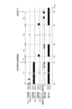
- FIG. 2 is a time chart showing the cleaning operation in a geothermal power generation system 100 according to one embodiment.
- the control device 140 may perform the cleaning operation by causing the first chemical addition device 130 to supply the cleaning agent and at the same time supplying the tracer reagent two or more times with an interval of five minutes or more between each supply, and stopping the supply of the cleaning agent and closing the first valve V101 (reducing valve) after the first liquid analyzer 111 detects the tracer reagent the same number of times as the number of supplies.
- V101 reducing valve
- the control device 140 sends a command to the tracer reagent injection pump 132a to discharge at least two supplies at intervals of 5 minutes or more with the first valve V101 (reduction valve) open, and sends a command to the cleaning agent injection pump 132b to continue discharging.
- the control device 140 After receiving a signal from the first liquid analyzer 111 that the tracer reagent has been detected the same number of times as the number of supplies, the control device 140 sends a command to the cleaning agent injection pump 132b to stop discharging at time t1, and at the same time sends a command to the first valve V101 to close it.
- the control device 140 opens the first valve V101 (reduction valve) two to three hours after it closes, and while the first valve V101 is open, it causes the first chemical additive device 130 to supply a corrosive agent, and then determines the cleaning state based on the concentration of metal ions detected by the first liquid analyzer 111.
- the control device 140 sends a command to the corrosive agent injection pump 132c to discharge at time t2, two to three hours (time T2) after time t1 when the cleaning agent injection pump 132b stops and the first valve V101 (reduction valve) closes, and simultaneously sends a command to the first valve V101 to open.
- Time T2 is the time required for the cleaning agent to come into sufficient contact with the inner wall of the piping of the reduction line L100. Then, after receiving the measured value of the metal ion concentration from the first liquid analyzer 111, the control device 140 judges the cleaning state at time t3, after time T3 has elapsed. Time T3 is the time required to check the cleaning state.
- the control device 140 determines that cleaning is not complete and performs the cleaning operation again from times T1 to T3, repeating the cleaning operation from times T1 to T3 until the concentration of metal ions detected by the first liquid analyzer 111 reaches the specified value.
- Time T4 is the time for repeating the cleaning operation from times T1 to T3.
- the time chart showing the cleaning operation at time T4 is the same as that for times T1 to T3, so it is not shown in Figure 2.
- the control device 140 determines that cleaning is complete at time t5, terminates the cleaning operation, and returns to normal operation.
- the time T5 from time t4 to time t5 is the final time of the time T3 for checking the cleaning state multiple times.
- control device 140 determines that the concentration of metal ions detected by the first liquid analyzer 111 has reached a specified value and cleaning has been completed, it causes geothermal water to flow into the residue inlet 113a, causes the scale chip collector 113 to collect the scale chips, and then causes the dissolving agent addition device 150 to inject a dissolving agent into the dissolving agent inlet 113b and closes the second valve V102 and the third valve V103.
- the control device 140 determines that the concentration of metal ions detected by the first liquid analyzer 111 has reached a specified value and cleaning has been completed, it is preferable that the control device 140 first opens the second valve V102 for one week or more and controls the flow of geothermal water into the residue inlet 113a.
- the control device 140 injects the dissolving agent into the dissolving agent inlet 113b using the dissolving agent adding device 150, and if the dissolving agent is a basic chemical, closes the second valve V102 and the third valve V103 when the pH of the fluid in the scale fragment collector 113 reaches a specified value.
- the pH of the fluid in the scale fragment collector 113 can be detected, for example, by a pH meter (not shown) provided in the scale fragment collector 113, and the control device 140 receives the measured pH value from the pH meter.
- the scale fragment collector 113 is maintained at a high temperature by the sensible heat of the reduction well 4, which improves the effect of the dissolving agent in the scale fragment collector 113 and promotes dissolution of the scale fragments. From the viewpoint of promoting dissolution of the scale fragments, it is preferable to position the scale fragment collector 113 so that the temperature inside the scale fragment collector 113 is maintained at 80°C or higher.
- the control device 140 closes the second valve V102 and the third valve V103, leaves them for 48 hours or more, and then opens the second valve V102, thereby controlling the sending of the fluid containing the dissolved scale particles in the scale particle collector 113 to the reinjection well 4 via the second pipe L102.
- the control device 140 applies pressure to the scale particle collector 113 using a pressure device (not shown), thereby pushing back the geothermal water flowing in from the residue inlet 113a via the open second valve V102, and controls the sending of the fluid containing the dissolved scale particles in the scale particle collector 113 to the reinjection well 4 via the second pipe L102.
- control device 140 controls the discharge of scale pieces, rock fragments, iron rust, etc. remaining in the scale piece collector 113 to the outside through the residue discharge port 113c.
- the control device 140 may further control the reduction pump 103, the liquid delivery pump 112, the fourth valve V104, the fifth valve V105, and the sixth valve V106.
- FIG. 1 is a schematic diagram showing another example of the geothermal power generation system 100 according to one embodiment, and Figure 4 is an enlarged view of a main portion of Figure 3.
- arrows indicate the flow of fluid.
- the geothermal power generation system 100 may include a first bypass pipe L121 that branches off from the return line L100 and is connected to the return line L100 downstream of the return pump 103, and a second bypass pipe L122 that branches off from the return line L100 and is connected to the return line L100 downstream of the first bypass pipe L121, as shown in FIG. 3 and FIG. 4.
- the geothermal power generation system 100 may also include a first switching valve V121 that is provided in the middle of the return line L100 and can switch the flow path of the return line L100 to the first bypass pipe L121, and a second switching valve V122 that is provided in the middle of the return line L100 and can switch the flow path of the return line L100 to the second bypass pipe L122.
- the geothermal power generation system 100 may include a chemical preparation section 115 provided in the first bypass pipe L121, a first gate valve V123 provided in the first bypass pipe L121 upstream of the chemical preparation section 115, a second gate valve V124 provided in the first bypass pipe L121 downstream of the chemical preparation section 115, a second chemical addition device 170, and an air introduction device 116.
- the drug preparation section 115 is the first bypass pipe L121 between the first gate valve V123 and the second gate valve V124, and is a section for introducing air into the drug in the drug preparation section 115 and adjusting the drug to be supplied to the return line L100.
- the second drug addition device 170 injects a drug into the drug preparation unit 115.
- the second drug addition device 170 may have a drug tank 171 that stores the drug, and a drug injection pump 172 that is connected to the drug tank 171 and ejects the drug toward the drug preparation unit 115.
- the number of drug tanks 171 is one in the example shown in FIG. 4, but is not limited to this and may be selected according to the number of types of drug used, and may be multiple.
- the number of drug injection pumps 172 can be selected according to the number of drug tanks 171.
- the chemical stored in the chemical tank 171 may be a cleaning agent, or a cleaning agent and a corrosive agent that is corrosive to the metal that constitutes the reduction line L100.
- the cleaning agent is a chemical used to remove and clean the scale adhering to the inside of the piping of the reduction line L100.
- the cleaning agent may be the same as that in the embodiment shown in FIG. 1.
- the corrosive agent is a chemical that is passed through the reduction line L100 after cleaning to dissolve the metals that make up the piping of the reduction line L100, and the cleaning state is determined based on the concentration of the dissolved metal ions.
- the corrosive agent may be the same as that in the embodiment shown in FIG. 1.
- the air introduction device 116 supplies air to the chemical in the chemical preparation section 115.
- Examples of the air introduction device 116 include an air compressor and a blower.
- the geothermal power generation system 100 may include an air filter 117 provided upstream of the air introduction device 116, and a drainage pump 118 that drains the geothermal water in the chemical preparation section 115.
- the geothermal power generation system 100 may include a ninth pipe L123 connected to the chemical preparation unit 115, a tenth pipe L124 branching off from the ninth pipe L123 and connected to the first bypass pipe L121 downstream of the second gate valve V124, an eleventh pipe L125 branching off from the ninth pipe L123 and connected to the outlet of the air introduction device 116, and a twelfth pipe L126 branching off midway from the eleventh pipe L125 and connected to the outlet of the chemical injection pump 172.
- the drainage pump 118 is provided midway along the tenth pipe L124.
- the ninth pipe L123 extends vertically downward from the chemical preparation unit 115.
- the ninth pipe L123 sends the cleaning agent and air to the chemical preparation unit 115, and also sends the geothermal water discharged from the chemical preparation unit 115 to the tenth pipe L124.
- the geothermal power generation system 100 may include a thirteenth pipe L127 connected to the chemical preparation unit 115 and extending vertically upward from the chemical preparation unit 115.
- the thirteenth pipe L127 discharges the air in the chemical preparation unit 115 to the outside, and also introduces air into the chemical preparation unit 115.
- the geothermal power generation system 100 may include a fifteenth valve V130 provided midway along the thirteenth pipe L127 to open and close the flow path of the thirteenth pipe L127.
- the geothermal power generation system 100 may include a seventh valve V125 provided in the ninth pipe L123 for opening and closing the flow path of the ninth pipe L123, an eighth valve V126 provided downstream of the drainage pump 118 in the tenth pipe L124 for opening and closing the flow path of the tenth pipe L124, a ninth valve V127 provided in the eleventh pipe L125 for opening and closing the flow path of the eleventh pipe L125 downstream of the branch point to the twelfth pipe L126, a tenth valve V129 for opening and closing the flow path upstream of the branch point to the twelfth pipe L126, and an eleventh valve V128 provided downstream of the chemical injection pump 172 in the twelfth pipe L126 for opening and closing the flow path of the twelfth pipe L126.
- the geothermal power generation system 100 may include an air separation section 120 provided in the second bypass pipe L122, a third gate valve V131 provided in the second bypass pipe L122 upstream of the air separation section 120, a fourth gate valve V132 provided in the second bypass pipe L122 downstream of the air separation section 120, and a second liquid analyzer 121 connected to the air separation section 120.
- the air separation section 120 is a section for separating (degassing) air from the fluids (geothermal water and chemicals) within the air separation section 120.
- the second liquid analyzer 121 measures, for example, pH, dielectric constant, or dissolved ion concentration.
- the geothermal power generation system 100 may include a 14th pipe L128 connected to the air separation unit 120 and extending vertically upward, and a 15th pipe L129 connected to the air separation unit 120 and extending vertically downward.
- the 14th pipe L128 discharges air separated in the air separation unit 120 to the outside.
- the geothermal power generation system 100 may include an air vent valve V133 provided midway along the 14th pipe L128.
- the air vent valve V133 automatically discharges air accumulated in the air separation unit 120.
- the 15th pipe L129 connects the air separation unit 120 to the second liquid analyzer 121, and sends the fluid in the air separation unit 120 to the second liquid analyzer 121.
- the geothermal power generation system 100 may include a liquid delivery pump 122 that is provided in the middle of the 15th pipe L129 and discharges the fluid flowing through the 15th pipe L129 toward the inlet of the second liquid analyzer 121, and a 12th valve V134 that is provided in the 15th pipe L129 upstream of the liquid delivery pump 122 and opens and closes the flow path of the 15th pipe L129.
- the control device 140 may switch between injecting and stopping the drug by the second drug addition device 170 and between introducing and stopping air by the air introduction device 116 based on the analysis results of the second liquid analyzer 121, and may also control the first switching valve V121, the second switching valve V122, and the first to fourth gate valves V123, V124, V131, and V132.
- Figures 5A to 5D are enlarged views of the main parts of Figure 3 to explain the cleaning operation in another example of the geothermal power generation system 100 according to one embodiment.
- open valves are shown in white
- closed valves are shown in black
- arrows indicate the flow of fluid.
- the control device 140 may repeat normal operation, a drainage operation to drain the geothermal water in the chemical preparation unit 115 after the normal operation, a chemical injection operation to inject a chemical into the chemical preparation unit 115 from which the geothermal water has been discharged, an air introduction operation to introduce air into the chemical injected into the chemical preparation unit 115, and a cleaning operation to switch the flow path of the reduction line L100 to the first bypass pipe L121 and the second bypass pipe L122 and perform cleaning.
- the control device 140 opens the seventh valve V125 and the eighth valve V126 and operates the drainage pump 118 to drain the geothermal water accumulated in the drug preparation unit 115 and send it to the first bypass pipe L121 downstream of the second gate valve V124 via the ninth pipe L123 and the tenth pipe L124.
- the control device 140 opens the fifteenth valve V130, whereby the geothermal water accumulated in the drug preparation unit 115 is drained and air is introduced into the drug preparation unit 115 via the thirteenth pipe L127.
- the control device 140 closes the eighth valve V126, opens the seventh valve V125, as well as the ninth valve V127 and the eleventh valve V128, operates the drug injection pump 172, and starts the drug injection operation by the second drug addition device 170.
- the drug is injected into the drug preparation unit 115, and the air inside the drug preparation unit 115 is discharged to the outside via the thirteenth pipe L127.
- the control device 140 opens the first to fourth gate valves V123, V124, V131, and V132, switches the flow path of the reduction line L100 to the first bypass pipe L121 and the second bypass pipe L122, and controls the flow of the drug containing air in the drug preparation unit 115 to the reduction line L100 and the second bypass pipe L122.
- the air introduced into the chemical in the chemical preparation section 115 is discharged to the outside through the air vent valve V133 and the 14th pipe L128 in the air separation section 120. That is, the geothermal power generation system 100 separates the air from the fluid (fluid containing geothermal water, chemicals, and air) in the air separation section 120, and then circulates the fluid from which the air has been separated to the reduction line L100 downstream of the second bypass pipe L122.
- control device 140 repeats normal operation, drainage operation, chemical injection operation, air introduction operation, and line switching operation again after a predetermined time has elapsed.
- the control device 140 may close the first switching valve V121 and the second switching valve V122, and open the first to fourth gate valves V123, V124, V131, and V132.
- the control device 140 may supply a corrosive agent by the second chemical addition device 170, and then determine the cleaning state based on the concentration of metal ions detected by the second liquid analyzer 121.
- the concentration of metal ions detected by the second liquid analyzer 121 may be the concentration of iron ions.
- the control device 140 may determine that cleaning is complete when the concentration of iron ions reaches 100 ppm.
- the analysis result analyzed by the first liquid analyzer 111 may be a dielectric constant.
- control device 140 determines that cleaning is not complete and may repeat normal operation, the drainage operation, the chemical injection operation, the air introduction operation, and the cleaning operation.
- control device 140 determines that cleaning is complete, executes normal operation, and may terminate the execution of subsequent drug injection operations, air introduction operations, and cleaning operations.
- the geothermal power generation system 100 includes a gas-liquid separator 3, a power generation device 101, a retention tank 102, a reduction line L100, a reduction pump 103, a chemical injection port 104 provided in the reduction line L100 between the retention tank 102 and the reduction pump 103, and a first chemical addition device 130.
- the geothermal power generation system 100 also includes a branching section 110, a first liquid analyzer 111, a scale chip collector 113 having a residue inlet 113a, a dissolving agent injection port 113b, and a residue outlet 113c, a dissolving agent addition device 150, and a control device 140 that switches between the injection operation and the stop of injection of the chemical by the first chemical addition device 130 and the injection operation and the stop of injection of the dissolving agent by the dissolving agent addition device 150 based on the analysis results of the first liquid analyzer 111.
- the control device 140 confirms the arrival of the chemical agent based on the analysis results of the first liquid analyzer 111 provided downstream of the return line L100, and switches between injecting the chemical agent by the first chemical agent adding device 130 and stopping the injection. Therefore, the geothermal power generation system 100 can spread the chemical agent throughout the entire return line L100 from the upstream side to the downstream side and clean the return line L100 without opening or disassembling the geothermal power generation system 100 as a closed system. In addition, even if scale pieces flow through the return line L100 after cleaning the return line L100, the geothermal power generation system 100 collects the scale pieces using the scale piece collector 113, and the control device 140 switches between injecting the solvent agent by the solvent agent adding device 150 and stopping the injection.
- the geothermal power generation system 100 can dissolve and remove scale pieces flowing through the return line L100 after cleaning, without opening or disassembling the geothermal power generation system 100 as a closed system. As a result, the geothermal power generation system 100 can sufficiently remove scale from the reduction line L100.
- the geothermal power generation system 100 includes a first valve V101
- the first chemical addition device 130 includes multiple chemical tanks 131a, 131b, and 131c and multiple chemical injection pumps 132a, 132b, and 132c
- the dissolving agent addition device 150 includes a dissolving agent tank 151 and a dissolving agent injection pump 152.
- the control device 140 controls the multiple chemical injection pumps 132a, 132b, and 132c, the dissolving agent injection pump 152, and the first valve V101 based on the analysis results of the first liquid analyzer 111.
- the control device 140 selects a chemical appropriate for the purpose from among a plurality of chemicals based on the analysis results of the first liquid analyzer 111, and controls the chemical injection pump that discharges the selected chemical, so that the geothermal power generation system 100 can supply the chemical appropriate for the purpose to the return line L100. Then, after the control device 140 distributes the chemical throughout the return line L100, the geothermal power generation system 100 closes the first valve V101, so that the chemical is sufficiently in contact with the inner wall of the piping of the return line L100, thereby enhancing the cleaning effect.
- control device 140 controls the dissolving agent injection pump 152 based on the analysis results of the first liquid analyzer 111, so that the geothermal power generation system 100 can sufficiently dissolve and remove scale pieces flowing through the return line L100 after cleaning. As a result of the above, the geothermal power generation system 100 can more sufficiently remove scale from the return line L100.
- the multiple chemical tanks 131a, 131b, and 131c contain a tracer reagent, a cleaning agent, and a corrosive agent that is corrosive to the metals that make up the reduction line L100.
- the geothermal power generation system 100 can confirm the arrival of the cleaning agent using the first liquid analyzer 111 by supplying the tracer reagent and the cleaning agent to the reduction line L100 at the same time, and can spread the cleaning agent throughout the entire reduction line L100 from the upstream side to the downstream side, thereby cleaning the reduction line L100.
- the geothermal power generation system 100 can supply a corrosive agent to the reduction line L100 to dissolve the metals that make up the piping of the reduction line L100, and can determine the cleaning state based on the concentration of the dissolved metal ions. Therefore, the geothermal power generation system 100 can more thoroughly remove scale from the reduction line L100.
- the cleaning agent includes one or more selected from an acidic agent, a basic agent, a chelating agent, a hydrogen peroxide-based agent, a dispersant, and a catalase-based agent. This allows the geothermal power generation system 100 to supply the reduction line L100 with the optimal cleaning agent for each of the soft mud, calcium carbonate, amorphous silica, iron rust, etc. contained in the scale.
- the corrosive agent is one selected from sulfuric acid, hydrochloric acid, acetic acid, and citric acid.
- the geothermal power generation system 100 supplies the reduction line L100 with one selected from sulfuric acid, hydrochloric acid, acetic acid, and citric acid as the corrosive agent, thereby dissolving the iron constituting the piping of the reduction line L100, and can determine the cleaning state based on the concentration of the dissolved iron ions.
- the dissolving agent is one selected from a basic agent, a fluoride-based agent, and an acidic agent. This allows the geothermal power generation system 100 to supply the scale fragment collector 113 with the most suitable dissolving agent for each of the calcium carbonate, amorphous silica, etc. contained in the scale.
- the control device 140 causes the first chemical additive device 130 to supply the cleaning agent and at the same time supply the tracer reagent two or more times with an interval of five minutes or more between each supply, and after the first liquid analyzer 111 detects the tracer reagent the same number of times as the number of supplies, stops the supply of the cleaning agent and closes the first valve V101, thereby performing the cleaning operation.
- the control device 140 confirms the arrival of the cleaning agent using the first liquid analyzer 111, and after the cleaning agent has spread throughout the entire return line L100, closes the first valve V101, allowing the geothermal power generation system 100 to bring the cleaning agent into sufficient contact with the inner wall of the piping of the return line L100, thereby enhancing the cleaning effect. Therefore, the geothermal power generation system 100 can more thoroughly remove scale from the return line L100.
- the control device 140 opens the first valve V101 two to three hours after the first valve V101 is closed, supplies a corrosive agent using the first chemical additive device 130, and then determines the cleaning state based on the concentration of metal ions detected by the first liquid analyzer 111. This allows the geothermal power generation system 100 to clean the return line L100 according to the cleaning state, and more thoroughly removes scale from the return line L100.
- the control device 140 determines that cleaning is not complete and performs the cleaning operation again, repeating the cleaning operation until the concentration of metal ions detected by the first liquid analyzer 111 reaches the specified value. This allows the geothermal power generation system 100 to prevent poor cleaning of the return line L100 and more thoroughly remove scale from the return line L100.
- control device 140 controls the discharge of scale particles remaining in the scale particle collector to the outside through the residue discharge port 113c. This allows the control device 140 to remove the sparingly soluble scale particles that could not be dissolved by the solvent in the scale particle collector 113.
- the geothermal power generation system 100 includes a first bypass pipe L121, a second bypass pipe L122, a first switching valve V121, a second switching valve V122, a chemical preparation unit 115, a first gate valve V123, a second gate valve V124, a second chemical addition device 170, an air introduction device 116, an air separation unit 120, a third gate valve V131, a fourth gate valve V132, and a second liquid analyzer 121.
- the control device 140 switches between injecting chemicals and stopping injection by the second chemical addition device 170 and switching between introducing air and stopping introduction by the air introduction device 116 based on the analysis results of the second liquid analyzer 121, and controls the first switching valve V121, the second switching valve V122, and the first to fourth gate valves V123, V124, V131, and V132.
- the geothermal power generation system 100 can clean the return line L100 even during normal operation (power generation).
- the control device 140 causes the air introduction device 116 to introduce air into the chemicals supplied by the second chemical addition device 170.
- the control device 140 then controls the first switching valve V121, the second switching valve V122, and the first to fourth gate valves V123, V124, V131, and V132 to switch the flow path of the return line L100 to the first bypass pipe L121 and the second bypass pipe L122, and causes the chemicals into which the air has been introduced to flow through the return line L100. This reduces the contact area between the chemicals and the geothermal water, and prevents the chemicals from being diluted while flowing through the return line L100.
- the control device 140 also causes the second chemical addition device 170 to supply a corrosive agent, and can determine the cleaning state based on the concentration of metal ions detected by the second liquid analyzer 121. Therefore, the geothermal power generation system 100 can continue cleaning until the return line L100 is sufficiently cleaned. As a result, the geothermal power generation system 100 can sufficiently remove scale from the return line L100 even during normal operation.
- the control device 140 repeats normal operation, a drainage operation to drain the geothermal water in the chemical preparation unit 115 after the normal operation, a chemical injection operation to inject a chemical into the chemical preparation unit 115 from which the geothermal water has been discharged, an air introduction operation to introduce air into the chemical injected into the chemical preparation unit 115, and a line switching operation to switch the flow path of the reduction line L100 to the first bypass pipe L121 and the second bypass pipe L122 to start cleaning.
- the geothermal power generation system 100 After separating the air from the fluid in the air separation section 120, the geothermal power generation system 100 passes the fluid from which the air has been separated through the reinjection line L100 downstream of the second bypass pipe L122. This allows the geothermal power generation system 100 to maintain the permeability of the geothermal water that is returned to the reinjection well 4 via the reinjection line L100 downstream of the second bypass pipe L122.
Landscapes
- Engineering & Computer Science (AREA)
- Chemical & Material Sciences (AREA)
- Combustion & Propulsion (AREA)
- Life Sciences & Earth Sciences (AREA)
- Sustainable Energy (AREA)
- Mechanical Engineering (AREA)
- General Engineering & Computer Science (AREA)
- Sustainable Development (AREA)
- Water Supply & Treatment (AREA)
- Cleaning By Liquid Or Steam (AREA)
- Preventing Corrosion Or Incrustation Of Metals (AREA)
Abstract
本発明の一態様に係る地熱発電システムは、気液分離器と、発電装置と、滞留槽と、還元ラインと、還元ポンプと、前記滞留槽と前記還元ポンプとの間の前記還元ラインに設けられた薬剤注入口と、前記薬剤注入口に薬剤を注入する第1薬剤添加装置と、前記還元ポンプの下流側且つ前記還元井の鉛直方向上方において、前記還元ラインの途中に設けられ、前記地熱水の流れを分岐する分岐部と、第1液体分析計と、スケール片捕集器と、溶解剤添加装置と、前記第1液体分析計の分析結果に基づき、前記第1薬剤添加装置による前記薬剤の注入操作及び注入停止の切り替え、並びに、前記溶解剤添加装置による前記溶解剤の注入操作及び注入停止の切り替えを行う制御装置とを備える。
Description
本発明は、地熱発電システムに関する。
地熱発電システムは、生産井から高温の地熱流体(地熱水及び地熱蒸気)を採取し、地熱流体から分離した地熱水又は地熱蒸気を利用して発電を行う。生産井から採取される地熱流体は、井戸水や河川水よりもカルシウムや溶存シリカ等を多く含んでいる。
生産井から採取した地熱水中のカルシウムや溶存シリカは、地熱発電システムにおいて、減圧されることにより濃縮され、配管内を流通するうちに冷やされ、溶解度が低下する。そして、地熱水に含まれるシリカや溶存シリカ等が過飽和状態となると、重合して炭酸カルシウムや非晶質シリカとなり、スケールとして析出する。スケールは、配管の内壁等に付着して、配管の閉塞等を生じる可能性があるため、地熱発電システムにおいて、スケールの付着が問題となっている。
特に、地熱発電システムにおいて、地熱水を還元井に戻すための還元ラインにスケールが付着し易く、還元ラインに付着したスケールを十分に洗浄することが求められている。例えば、特許文献1に記載の地熱発電システムでは、汽水分離器の後流側で、分離熱水に、酸化剤として過酸化水素水を供給し、地熱水系統におけるシリカ成分のスケール付着を防止している。
しかしながら、通常、地熱発電システムにおいて、還元ラインは、長距離に亘って配置されるため、還元ラインの上流側で供給した洗浄剤が、下流側になるに従い希釈されるため、下流側の配管に付着したスケールの洗浄が不十分となり、洗浄不良が発生する、という問題があった。
本発明の一態様は、還元ラインのスケールを十分に除去することができる地熱発電システムを提供する。
本発明の一態様に係る地熱発電システムは、生産井より噴出した地熱流体から地熱水と地熱蒸気とを分離する気液分離器と、前記気液分離器で分離された前記地熱水又は前記地熱蒸気を熱源として発電を行う発電装置と、前記発電装置で熱回収された前記地熱水を貯留する滞留槽と、前記滞留槽の出口部と還元井とを連結する還元ラインと、前記還元ラインの途中に設けられ、前記滞留槽から排出された前記地熱水を還元井に返送する還元ポンプと、前記滞留槽と前記還元ポンプとの間の前記還元ラインに設けられた薬剤注入口と、前記薬剤注入口に薬剤を注入する第1薬剤添加装置と、前記還元ポンプの下流側且つ前記還元井の鉛直方向上方において、前記還元ラインの途中に設けられ、前記地熱水の流れを分岐する分岐部と、前記分岐部から鉛直方向上方に連結された第1液体分析計と、前記分岐部から水平方向に連結され、残渣投入口と、溶解剤注入口と、残渣排出口とを有するスケール片捕集器と、前記溶解剤注入口に溶解剤を注入する溶解剤添加装置と、前記第1液体分析計の分析結果に基づき、前記第1薬剤添加装置による前記薬剤の注入操作及び注入停止の切り替え、並びに、前記溶解剤添加装置による前記溶解剤の注入操作及び注入停止の切り替えを行う制御装置とを備える。
本発明の一態様に係る地熱発電システムによれば、還元ラインのスケールを十分に除去することができる。
以下、本発明を実施するための形態について図面を参照しながら説明する。まず、通常運転(発電)を停止して還元ラインL100を洗浄する場合の地熱発電システム100の実施形態について説明する。
図1は、一実施形態による地熱発電システム100の概略構成図である。図1に示すように、地熱発電システム100は、気液分離器3、発電装置101、滞留槽102、還元ラインL100、還元ポンプ103、薬剤注入口104、第1薬剤添加装置130及び制御装置140を備える。図1において、矢印は流体の流れを示す。
地熱発電システム100において、生産井2から採取された地熱流体は、気液分離器3に送られる。気液分離器3は、生産井2より噴出した地熱流体から地熱水と地熱蒸気とを分離する。気液分離器3で分離された地熱水及び地熱蒸気は、配管を介して発電装置101に送られ、発電装置101は、気液分離器3で分離された地熱水又は地熱蒸気を熱源として発電を行う。発電装置101で熱回収された地熱水は、配管を介して滞留槽102に導入される。
図1に示す例では、気液分離器3で分離された地熱蒸気は、フラッシュ発電装置101aに送られ、フラッシュ発電装置101aは、気液分離器3で分離された地熱蒸気を熱源として発電を行い、気液分離器3で分離された地熱水は、バイナリー発電装置101bに送られ、バイナリー発電装置101bは、気液分離器3で分離された地熱水を熱源として発電を行う。
発電装置101は、特に限定されず、フラッシュ発電装置101a及びバイナリー発電装置101bを有していてよく、フラッシュ発電装置101a及びバイナリー発電装置101bのいずれか一方を有していてもよい。
フラッシュ発電装置101aは、気液分離器3で分離された地熱蒸気を供給することにより回転するタービン、タービンに接続された発電機、タービンから排出された地熱蒸気を凝縮する復水器、復水器で凝縮された凝縮水を冷却する冷却塔等を有する。バイナリー発電装置101bは、熱交換して低沸点の熱媒体を蒸発させる媒体蒸発器、気化した熱媒体を供給することにより回転するタービン、発電機、媒体凝縮器等を有する。
滞留槽102は、発電装置101で熱回収された地熱水を貯留する。そして、地熱水中のシリカの重合反応を進行させ、シリカ系不溶成分が十分に凝集沈澱するまで滞留させる。
還元ラインL100は、滞留槽102の出口部と還元井4とを連結するラインである。
還元ポンプ103は、還元ラインL100の途中に設けられ、滞留槽102から排出された地熱水を還元井4に返送する。滞留槽102から排出された地熱水は、還元ポンプ103により、還元ラインL100を介して還元井4に戻される。
薬剤注入口104は、滞留槽102と還元ポンプ103との間の還元ラインL100に設けられている。
第1薬剤添加装置130は、薬剤注入口に薬剤を注入する装置であり、薬剤を収容する複数の薬剤タンク131a、131b、131cと、複数の薬剤タンク131a、131b、131cのそれぞれに接続され、薬剤を薬剤注入口104に向けて吐出する複数の薬剤注入ポンプ132a、132b、132cとを有していてよい。薬剤タンク131a、131b、131cの数は、図1に示す例では3つであるが、これに限らず、使用する薬剤種の数に応じて選択することができ、4つ以上であってもよい。薬剤注入ポンプ132a、132b、132cの数は、薬剤タンク131a、131b、131cの数に応じて選択することができる。
複数の薬剤タンク131a、131b、131cには、それぞれ、トレーサ試薬、洗浄剤、及び還元ラインL100を構成する金属に対して腐食性を有する腐食剤が収容されていてよい。例えば、薬剤タンク131aには、トレーサ試薬を収容し、薬剤タンク131bには、洗浄剤を収容し、薬剤タンク131cには、腐食剤を収容する。以後、本明細書において、トレーサ試薬を収容した薬剤タンク131aに接続された薬剤注入ポンプをトレーサ試薬注入ポンプ132aと、洗浄剤を収容した薬剤タンク131bに接続された薬剤注入ポンプを洗浄剤注入ポンプ132bと、腐食剤を収容した薬剤タンク131cに接続された薬剤注入ポンプを腐食剤注入ポンプ132cと、称する場合がある。
トレーサ試薬は、還元ラインL100の下流側まで洗浄剤が到達したことを確認するための薬剤である。トレーサ試薬としては、例えば、ヨウ素、臭素等のハロゲン、ヨウ素131、臭素82、トリチウム等の放射性同位体、安息香酸ナトリウム、トルエンスルホン酸ナトリウム、キシレンスルホン酸ナトリウム、ベンゼンスルホン酸ナトリウム、1-ナフタレンスルホン酸、1,5-ナフタレンジスルホン酸等の芳香族スルホン酸塩、フルオレセインナトリウム、ローダミンWT、2,6,8-ナフチルアミンジスルホン酸(アミノG酸)等の蛍光染料、金属指示薬、安息香酸等が挙げられる。これらの中でも、トレーサ試薬は、芳香族スルホン酸塩であることが好ましい。
洗浄剤は、還元ラインL100の配管内に付着したスケールを除去し、洗浄するための薬剤である。洗浄剤は、例えば、酸性薬剤、塩基性薬剤、キレート剤、過酸化水素系薬剤、分散剤、及びカタラーゼ系薬剤から選択される1種以上を含む薬剤とすることができる。
酸性薬剤は、カルシウム系のスケールを溶解するために用いることができる。酸性薬剤としては、例えば、硫酸、塩酸、酢酸、クエン酸等が挙げられる。塩基性薬剤は、シリカ系のスケール(非晶質シリカ)を溶解するために用いることができる。塩基性薬剤としては、例えば、水酸化ナトリウム、水酸化カリウム、アンモニウム塩類等が挙げられる。キレート剤は、他の洗浄剤を使用する前に、予め、pH調整下において、地熱水中の溶存金属をマスキングし、他の洗浄剤の浪費を抑制するために用いることができる。キレート剤としては、例えば、エチレンジアミン四酢酸(EDTA)、ニトリロ三酢酸(NTA)、ヒドロキシエチレンジアミン三酢酸(HEDTA)、ジエチレントリアミン五酢酸(DTPA)、トリメタノールアミン、グルコン酸ソーダ等が挙げられる。過酸化水素系薬剤は、軟泥質を溶解するために用いることができる。過酸化水素系薬剤としては、例えば、過酸化水素水が挙げられる。分散剤は、配管の内壁等に付着したスケールを分散させ剥離するために用いることができる。分散剤としては、例えば、ポリアクリル酸ナトリウム、各種の界面活性剤等が挙げられる。カタラーゼ系薬剤は、過酸化水素系薬剤を使用した後、地熱水中に残存する過酸化水素系薬剤を分解するために用いることができる。
腐食剤は、洗浄後の還元ラインL100に流通させ、還元ラインL100の配管を構成する金属を溶出させ、溶出した金属イオンの濃度によって、洗浄状態を判断するための薬剤である。腐食剤は、例えば、硫酸、塩酸、酢酸、及びクエン酸から選択される1種とすることができる。
地熱発電システム100は、還元ラインL100の薬剤注入口104と連結された第4配管L104と、第4配管L104の途中に設けられ、第4配管L104の流路を開閉する第5の弁V105を備えていてよい。また、第1薬剤添加装置130は、第4配管L104から分岐して薬剤注入ポンプ132aの吐出口と連結する第6配管L106と、第4配管L104から分岐して薬剤注入ポンプ132bの吐出口と連結する第7配管L107と、第4配管L104から分岐して薬剤注入ポンプ132cの吐出口と連結する第8配管L108とを有していてよい。
地熱発電システム100は、滞留槽102と還元ポンプ103との距離等により、必要に応じて、第4配管L104から分岐し、滞留槽102の入口部まで延びる、仮設の第5配管L105を備えていてよい。この場合、第1薬剤添加装置130から供給された薬剤は、滞留槽102内の地熱水と共に、滞留槽102の出口部から還元ラインL100に供給される。
地熱発電システム100は、還元ポンプ103の下流側且つ還元井4の鉛直方向上方において、還元ラインL100の途中に設けられ、地熱水の流れを分岐する分岐部110と、分岐部110から鉛直方向上方に連結された第1液体分析計111と、分岐部110から水平方向に連結されたスケール片捕集器113とを備える。分岐部110は、地熱水の流れを四方に分岐し、例えば、四方弁であってよい。地熱発電システム100は、分岐部110と還元井4との間の還元ラインL100に設けられ、分岐部110と還元井4との間の流路を開閉する第1の弁V101(還元弁)を備えていてよい。
第1液体分析計111は、分岐部110から分岐した第3配管L103に連結されている。第1液体分析計111は、流体に含まれる成分を分析し、検出する。第1液体分析計111は、少なくともトレーサ試薬を検出する。また、第1液体分析計111は、pH、誘電率、又は溶存イオン濃度を測定する。第1液体分析計111は、例えば、高速液体クロマトグラフであってよい。
地熱発電システム100は、第3配管L103の途中に設けられ、還元ラインL100を流通する流体を第1液体分析計111の入口部に向けて吐出する送液ポンプ112と、送液ポンプ112の上流側における第3配管L103に設けられ、第3配管L103の流路を開閉する第4の弁V104とを備えていてよい。
スケール片捕集器113は、残渣投入口113aと、溶解剤注入口113bと、残渣排出口113cとを有し、還元ラインL100の洗浄完了後に、遅延して還元ラインL100を流れるスケール片を捕集する。地熱発電システム100は、分岐部110と残渣投入口113aとを連結する第1配管L101と、第1配管L101に設けられ、第1配管L101の流路を開閉する第2の弁V102とを備えていてよい。
地熱発電システム100は、スケール片捕集器113の溶解剤注入口113bに溶解剤を注入する溶解剤添加装置150を備える。溶解剤添加装置150は、溶解剤を収容する溶解剤タンク151と、溶解剤タンク151に接続され、溶解剤を溶解剤注入口113bに向けて吐出する溶解剤注入ポンプ152とを有していてよい。溶解剤は、スケール片捕集器113に捕集されたスケールを溶解する薬剤であり、例えば、塩基性薬剤、フッ化物系薬剤、及び酸性薬剤から選択される1種とすることができる。
塩基性薬剤及び酸性薬剤としては、上述の洗浄剤と同様の薬剤を用いることができる。フッ化物系薬剤としては、例えば、フッ化水素酸、ヘキサフルオロリン酸、フッ化アンモニウム等が挙げられる。
地熱発電システム100は、溶解剤注入口113bと溶解剤注入ポンプ152の吐出口とを連結する第2配管L102と、第2配管L102に設けられ、第2配管L102の流路を開閉する第3の弁V103とを備えていてよい。
制御装置140は、第1液体分析計111の分析結果に基づき、第1薬剤添加装置130による薬剤の注入操作及び注入停止の切り替え、並びに、溶解剤添加装置150による溶解剤の注入操作及び注入停止の切り替えを行う。具体的には、制御装置140は、第1液体分析計111の分析結果に基づき、複数の薬剤注入ポンプ132a、132b、132c、溶解剤注入ポンプ152、及び第1の弁V101を制御する。
図2は、一実施形態による地熱発電システム100における洗浄の動作を示すタイムチャートである。制御装置140は、第1薬剤添加装置130により、洗浄剤を供給させると同時に、トレーサ試薬を5分以上の間隔を空けて2回以上の供給回数にて供給させ、第1液体分析計111がトレーサ試薬を当該供給回数と同じ回数検知した後、洗浄剤の供給を停止させ、第1の弁V101(還元弁)を閉止することにより、洗浄操作を実行してよい。
図2に示すように、制御装置140は、時点t0において、第1の弁V101(還元弁)を開放した状態で、トレーサ試薬注入ポンプ132aに、5分以上の間隔を空けて2回以上の供給回数にて吐出する指令を送ると共に、洗浄剤注入ポンプ132bに継続して吐出する指令を送る。制御装置140は、第1液体分析計111から、トレーサ試薬を当該供給回数と同じ回数検知した信号を受信した後、時点t1において、洗浄剤注入ポンプ132bに吐出を停止する指令を送ると同時に、第1の弁V101に閉止する指令を送る。制御装置140は、トレーサ試薬を当該供給回数と同じ回数検知した信号を受信したことにより、洗浄剤が還元ラインL100の下流側まで到達したことを確認することができる。時間T1は、洗浄剤が還元ラインL100の下流側まで到達させるための時間である。
制御装置140は、第1の弁V101(還元弁)を閉止した時から、2時間~3時間経過後、第1の弁V101を開放し、第1の弁V101を開放した状態で、第1薬剤添加装置130により腐食剤を供給させた後、第1液体分析計111にて検出された金属イオンの濃度に基づき、洗浄状態を判断する。
制御装置140は、洗浄剤注入ポンプ132bが停止し、第1の弁V101(還元弁)が閉止した時点t1から2時間~3時間(時間T2)経過した後、時点t2において、腐食剤注入ポンプ132cに吐出する指令を送ると同時に、第1の弁V101に開放する指令を送る。時間T2は、還元ラインL100の配管の内壁に洗浄剤を十分に接触させるための時間である。そして、制御装置140は、第1液体分析計111から、金属イオンの濃度の測定値を受信した後、時間T3経過後、時点t3において、洗浄状態を判断する。時間T3は、洗浄状態を確認するための時間である。
洗浄が進む程、配管の内壁が露出し、配管を構成する金属が流体に溶け出すため、流体に含まれる金属イオンの濃度が上昇する。第1液体分析計111にて検出される金属イオンの濃度は、鉄イオンの濃度であってよい。例えば、制御装置140は、鉄イオンの濃度が100ppmに達したときに、洗浄完了と判断してもよい。第1液体分析計111にて分析される分析結果は、誘電率であってもよい。
制御装置140は、第1液体分析計111にて検出された金属イオンの濃度が規定値未満である場合、洗浄が完了していないと判断し、再度、時間T1~T3の洗浄操作を実行し、第1液体分析計111にて検出された金属イオンの濃度が規定値に到達するまで、時間T1~T3の洗浄操作を繰り返す。時間T4は、時間T1~T3の洗浄操作を繰り返す時間である。時間T4における、洗浄の動作を示すタイムチャートは、時間T1~T3と同様であるため、図2では記載を省略する。
制御装置140は、第1液体分析計111にて検出された金属イオンの濃度が規定値に到達した場合、時点t5において、洗浄完了と判断し、洗浄操作を終了し通常運転に戻る。時点t4から時点t5の時間T5は、複数回の洗浄状態を確認するための時間T3のうち最終回の時間である。
制御装置140は、第1液体分析計111にて検出された金属イオンの濃度が規定値に到達し、洗浄が完了したと判断した場合、残渣投入口113aに地熱水を流入させ、スケール片捕集器113にスケール片を捕集させた後、溶解剤添加装置150により溶解剤を溶解剤注入口113bに注入させ、第2の弁V102及び第3の弁V103を閉止する。具体的には、制御装置140は、まず、第1液体分析計111にて検出された金属イオンの濃度が規定値に到達し、洗浄が完了したと判断した場合、1週間以上の間、第2の弁V102を開放し、残渣投入口113aに地熱水を流入させる制御を行うことが好ましい。これにより、地熱発電システム100は、洗浄後、遅延して還元ラインL100を流れるスケール片をスケール片捕集器113に十分に捕集することができる。次に、制御装置140は、溶解剤添加装置150により溶解剤を溶解剤注入口113bに注入させ、溶解剤が塩基性薬剤である場合、スケール片捕集器113内の流体のpHが規定値になったとき、第2の弁V102及び第3の弁V103を閉止する。なお、スケール片捕集器113内の流体のpHは、例えば、スケール片捕集器113に設けられた、図示しないpH測定器によって検出することができ、制御装置140は、pH測定器からpHの測定値を受信する。
スケール片捕集器113は、還元井4の顕熱により高温に維持されるため、スケール片捕集器113内の溶解剤の効果を向上させ、スケール片の溶解を促進することができる。スケール片の溶解を促進する観点から、スケール片捕集器113内の温度を80℃以上に維持するようにスケール片捕集器113を配置することが好ましい。
制御装置140は、第2の弁V102及び第3の弁V103を閉止し、48時間以上放置した後、第2の弁V102を開放することで、スケール片捕集器113内の溶解させたスケール片を含む流体を第2配管L102を介して還元井4へ送る制御を行う。具体的には、制御装置140は、図示しない加圧装置によって、スケール片捕集器113内に圧力を印加させることにより、開放した第2の弁V102を介して残渣投入口113aから流入する地熱水を押し戻し、スケール片捕集器113内の溶解させたスケール片を含む流体を第2配管L102を介して還元井4へ送る制御を行う。
そして、制御装置140は、スケール片捕集器113内に残留したスケール片、岩石の破片、鉄錆等を残渣排出口113cから外部に排出する制御を行う。
制御装置140は、さらに、還元ポンプ103、送液ポンプ112、第4の弁V104、第5の弁V105、及び第6の弁V106を制御してもよい。
次に、地熱発電システム100の他の例について説明する。地熱発電システム100の他の例は、通常運転中(発電中)に還元ラインL100を洗浄する場合の地熱発電システム100の実施形態である。図3は、一実施形態による地熱発電システム100の他の例を示す概略構成図であり、図4は、図3の要部拡大図である。図3及び図4において、矢印は流体の流れを示す。
地熱発電システム100は、図1及び図2に示す上述の構成に加えて、図3及び図4に示すように、還元ポンプ103の下流側において、還元ラインL100から分岐し、還元ラインL100に連結された第1バイパス配管L121と、第1バイパス配管L121の下流側において、還元ラインL100から分岐し、還元ラインL100に連結された第2バイパス配管L122とを備えていてよい。また、地熱発電システム100は、還元ラインL100の途中に設けられ、還元ラインL100の流路を第1バイパス配管L121へ切り替え可能な第1切替弁V121と、還元ラインL100の途中に設けられ、還元ラインL100の流路を第2バイパス配管L122へ切り替え可能な第2切替弁V122とを備えていてよい。
さらに、地熱発電システム100は、図4に示すように、第1バイパス配管L121に設けられた薬剤調整部115、薬剤調整部115の上流側の第1バイパス配管L121に設けられた第1仕切弁V123、及び薬剤調整部115の下流側の第1バイパス配管L121に設けられた第2仕切弁V124と、第2薬剤添加装置170と、空気導入装置116とを備えていてよい。
薬剤調整部115は、第1仕切弁V123と第2仕切弁V124との間の第1バイパス配管L121であり、薬剤調整部115内の薬剤に空気を導入し、還元ラインL100に供給する薬剤を調整するための部分である。
第2薬剤添加装置170は、薬剤調整部115に薬剤を注入する。第2薬剤添加装置170は、薬剤を収容する薬剤タンク171と、薬剤タンク171に接続され、薬剤を薬剤調整部115に向けて吐出する薬剤注入ポンプ172とを有していてよい。薬剤タンク171の数は、図4に示す例では1つであるが、これに限らず、使用する薬剤種の数に応じて選択することができ、複数であってもよい。薬剤注入ポンプ172の数は、薬剤タンク171の数に応じて選択することができる。
薬剤タンク171に収容される薬剤は、洗浄剤、又は洗浄剤及び還元ラインL100を構成する金属に対して腐食性を有する腐食剤が収容されていてよい。薬剤タンク171の数は、複数であってよく、薬剤が洗浄剤及び腐食剤である場合、洗浄剤と腐食剤とは別々の薬剤タンク171に収容される。
洗浄剤は、還元ラインL100の配管内に付着したスケールを除去し、洗浄するための薬剤である。洗浄剤としては、図1に示す実施形態と同様の洗浄剤を用いることができる。
腐食剤は、洗浄後の還元ラインL100に流通させ、還元ラインL100の配管を構成する金属を溶出させ、溶出した金属イオンの濃度によって、洗浄状態を判断するための薬剤である。腐食剤としては、図1に示す実施形態と同様の腐食剤を用いることができる。
空気導入装置116は、薬剤調整部115内の薬剤に空気を供給する。空気導入装置116としては、例えば、エアコンプレッサ、ブロア等が挙げられる。地熱発電システム100は、空気導入装置116の上流側に設けられたエアフィルタ117と、薬剤調整部115内の地熱水を排水する排水ポンプ118を備えていてよい。
地熱発電システム100は、薬剤調整部115に連結された第9配管L123と、第9配管L123から分岐し、第2仕切弁V124の下流側の第1バイパス配管L121に連結された第10配管L124と、第9配管L123から分岐し、空気導入装置116の吹出口に連結された第11配管L125と、第11配管L125の途中から分岐し、薬剤注入ポンプ172の吐出口に連結された第12配管L126とを備えていてよい。排水ポンプ118は、第10配管L124の途中に設けられている。
第9配管L123は、薬剤調整部115から鉛直方向下方に延びて設けられている。第9配管L123は、洗浄剤及び空気を薬剤調整部115へ送り、また、薬剤調整部115から排出される地熱水を第10配管L124へ送る。地熱発電システム100は、薬剤調整部115に連結され、薬剤調整部115から鉛直方向上方に延びて設けられた第13配管L127を備えていてよい。第13配管L127は、薬剤調整部115内の空気を外部に排出し、また、薬剤調整部115内に空気を導入する。地熱発電システム100は、第13配管L127の途中に設けられ、第13配管L127の流路を開閉する第15の弁V130を備えていてよい。
地熱発電システム100は、第9配管L123の途中に設けられ、第9配管L123の流路を開閉する第7の弁V125と、第10配管L124における排水ポンプ118より下流側に設けられ、第10配管L124の流路を開閉する第8の弁V126と、第11配管L125の途中に設けられ、第11配管L125における、第12配管L126への分岐点より下流側の流路を開閉する第9の弁V127と、第12配管L126への分岐点より上流側の流路を開閉する第10の弁V129と、第12配管L126における薬剤注入ポンプ172より下流側に設けられ、第12配管L126の流路を開閉する第11の弁V128とを備えていてよい。
地熱発電システム100は、第2バイパス配管L122に設けられた空気分離部120、空気分離部120の上流側の第2バイパス配管L122に設けられた第3仕切弁V131、及び空気分離部120の下流側の第2バイパス配管L122に設けられた第4仕切弁V132と、空気分離部120に接続された第2液体分析計121とを備えていてよい。
空気分離部120は、空気分離部120内の流体(地熱水及び薬剤)から空気を分離する(脱気する)ための部分である。第2液体分析計121は、例えば、pH、誘電率、又は溶存イオン濃度を測定する。
地熱発電システム100は、空気分離部120に連結され鉛直方向上方に延びる第14配管L128と、空気分離部120に連結され鉛直方向下方に延びる第15配管L129とを備えていてよい。第14配管L128は、空気分離部120内で分離された空気を外部に排出する。地熱発電システム100は、第14配管L128の途中に設けられた、空気抜き弁V133を備えていてよい。空気抜き弁V133は、空気分離部120内に溜まった空気を自動的に排出する。第15配管L129は、空気分離部120と第2液体分析計121とを連結し、空気分離部120内の流体を第2液体分析計121へ送る。地熱発電システム100は、第15配管L129の途中に設けられ、第15配管L129を流通する流体を第2液体分析計121の入口部に向けて吐出する送液ポンプ122と、送液ポンプ122の上流側における第15配管L129に設けられ、第15配管L129の流路を開閉する第12の弁V134とを備えていてよい。
制御装置140は、第2液体分析計121の分析結果に基づき、第2薬剤添加装置170による薬剤の注入操作及び注入停止の切り替え、並びに空気導入装置116による空気の導入操作及び導入停止の切り替えを行うと共に、第1切替弁V121、第2切替弁V122、及び第1~第4仕切弁V123、V124、V131、V132を制御してよい。
次に、地熱発電システム100の他の例における洗浄の動作について詳細に説明する。図5A~図5Dは、一実施形態による地熱発電システム100の他の例における洗浄の動作を説明するための図3の要部拡大図である。図5A~図5Dにおいて、開放している弁は、白色で示し、閉止している弁は黒色で示し、矢印は流体の流れを示す。
制御装置140は、通常運転と、通常運転の後、薬剤調整部115内の地熱水を排出する排水操作と、地熱水が排出された薬剤調整部115に薬剤を注入する薬剤注入操作と、薬剤調整部115に注入された薬剤に空気を導入する空気導入操作と、還元ラインL100の流路を第1バイパス配管L121及び第2バイパス配管L122へ切り替えて洗浄を行う洗浄操作とを繰り返してよい。
制御装置140は、図5Aに示すように、通常運転において、第1切替弁V121及び第2切替弁V122を開放し、第1~第4仕切弁V123、V124、V131、V132を閉止する。通常運転において、地熱水は、還元ラインL100を流通し、第1バイパス配管L121及び第2バイパス配管L122には流通しない。
次に、制御装置140は、図5Bに示すように、薬剤調整部115内の地熱水を排出する排水操作において、第7の弁V125及び第8の弁V126を開放し、排水ポンプ118を作動させ、薬剤調整部115に溜まった地熱水を排出し、第9配管L123及び第10配管L124を介して、第2仕切弁V124より下流側の第1バイパス配管L121へ送る。このとき、制御装置140が、第15の弁V130を開放することにより、薬剤調整部115に溜まった地熱水が排水されると共に、第13配管L127を介して薬剤調整部115内に空気が導入される。
次に、制御装置140は、図5Cに示すように、薬剤調整部115に薬剤を注入する薬剤注入操作において、第8の弁V126を閉止し、第7の弁V125に加え、第9の弁V127及び第11の弁V128を開放し、薬剤注入ポンプ172を作動させ、第2薬剤添加装置170による薬剤の注入操作を開始する。このとき、薬剤調整部115に薬剤が注入されると共に、第13配管L127を介して薬剤調整部115内の空気が外部に排出される。
次に、制御装置140は、図5Dに示すように、薬剤に空気を導入する空気導入操作において、第11の弁V128及び第15の弁V130を閉止し、第7の弁V125及び第9の弁V127に加え、第10の弁V129を開放する。また、制御装置140は、薬剤注入ポンプ172を停止させ、第2薬剤添加装置170による薬剤の注入を停止すると共に、空気導入装置116を作動させ、第9配管L123及び第11配管L125を介して薬剤調整部115内の薬剤に空気を供給する制御を行う。
そして、制御装置140は、還元ラインL100の流路を第1バイパス配管L121及び第2バイパス配管L122へ切り替えて洗浄を開始するライン切替操作において、第1~第4仕切弁V123、V124、V131、V132を開放し、還元ラインL100の流路を第1バイパス配管L121及び第2バイパス配管L122へ切り替えて、薬剤調整部115内の空気を含む薬剤を還元ラインL100及び第2バイパス配管L122へ流通させる制御を行う。
薬剤調整部115内の薬剤に導入された空気は、空気分離部120で空気抜き弁V133及び第14配管L128を介して外部に排出される。即ち、地熱発電システム100は、空気分離部120内の流体(地熱水、薬剤及び空気を含む流体)から空気を分離した後、空気を分離した流体を第2バイパス配管L122より下流側の還元ラインL100に流通させる。
制御装置140は、ライン切替操作の後、所定時間経過後、再度、通常運転と、排水操作と、薬剤注入操作と、空気導入操作と、ライン切替操作とを繰り返す。
制御装置140は、洗浄操作を実行した後、第1切替弁V121及び第2切替弁V122を閉止し、第1~第4仕切弁V123、V124、V131、V132を開放した状態で、第2薬剤添加装置170による薬剤の注入停止後、第2薬剤添加装置170により腐食剤を供給させた後、第2液体分析計121にて検出された金属イオンの濃度に基づき、洗浄状態を判断してよい。第2液体分析計121にて検出される金属イオンの濃度は、鉄イオンの濃度であってよい。例えば、制御装置140は、鉄イオンの濃度が100ppmに達したときに、洗浄完了と判断してもよい。第1液体分析計111にて分析される分析結果は、誘電率であってもよい。
制御装置140は、第2液体分析計121にて検出された金属イオンの濃度が規定値未満である場合、洗浄が完了していないと判断し、再度、通常運転、排水操作と、薬剤注入操作と、空気導入操作と、洗浄操作とを繰り返してよい。
制御装置140は、第2液体分析計121にて検出された金属イオンの濃度が規定値に到達した場合、洗浄完了と判断し、通常運転を実行し、それ以降の薬剤注入操作、空気導入操作、及び洗浄操作の実行を終了してよい。
地熱発電システム100は、気液分離器3と、発電装置101と、滞留槽102と、還元ラインL100と、還元ポンプ103と、滞留槽102と還元ポンプ103との間の還元ラインL100に設けられた薬剤注入口104と、第1薬剤添加装置130とを備える。また、地熱発電システム100は、分岐部110と、第1液体分析計111と、残渣投入口113a、溶解剤注入口113b、及び残渣排出口113cを有するスケール片捕集器113と、溶解剤添加装置150と、第1液体分析計111の分析結果に基づき、第1薬剤添加装置130による薬剤の注入操作及び注入停止の切り替え、並びに、溶解剤添加装置150による溶解剤の注入操作及び注入停止の切り替えを行う制御装置140とを備える。
この構成により、制御装置140は、還元ラインL100の下流側に設けられた第1液体分析計111の分析結果に基づき、薬剤の到達を確認し、第1薬剤添加装置130による薬剤の注入操作及び注入停止の切り替えを行う。よって、地熱発電システム100は、地熱発電システム100を開放又は分解することなく閉鎖系とした状態で、還元ラインL100の上流側から下流側までの全体に薬剤を行き渡らせ、還元ラインL100を洗浄することができる。また、地熱発電システム100は、還元ラインL100を洗浄した後、還元ラインL100をスケール片が流通する場合においても、スケール片捕集器113によりスケール片を捕集し、制御装置140は、溶解剤添加装置150による溶解剤の注入操作及び注入停止の切り替えを行う。よって、地熱発電システム100は、地熱発電システム100を開放又は分解することなく閉鎖系とした状態で、洗浄後に還元ラインL100を流通するスケール片を溶解し除去することができる。以上により、地熱発電システム100は、還元ラインL100のスケールを十分に除去することができる。
具体的には、地熱発電システム100は、第1の弁V101を備え、第1薬剤添加装置130は、複数の薬剤タンク131a、131b、131cと、複数の薬剤注入ポンプ132a、132b、132cとを有し、溶解剤添加装置150は、溶解剤タンク151と、溶解剤注入ポンプ152とを有する。また、制御装置140は、第1液体分析計111の分析結果に基づき、複数の薬剤注入ポンプ132a、132b、132c、溶解剤注入ポンプ152、及び第1の弁V101を制御する。
この構成により、制御装置140が、第1液体分析計111の分析結果に基づき、複数の薬剤の中から目的に応じた薬剤を選択し、当該薬剤を吐出する薬剤注入ポンプを制御することにより、地熱発電システム100は、還元ラインL100に目的に応じた薬剤を供給することができる。そして、制御装置140が、還元ラインL100の全体に薬剤を行き渡らせた後、第1の弁V101を閉じることにより、地熱発電システム100は、還元ラインL100の配管の内壁に薬剤を十分に接触させ、洗浄効果を高めることができる。また、制御装置140が、第1液体分析計111の分析結果に基づき、溶解剤注入ポンプ152を制御することにより、地熱発電システム100は、洗浄後に還元ラインL100を流通するスケール片を十分に溶解し除去することができる。以上により、地熱発電システム100は、還元ラインL100のスケールをより十分に除去することができる。
地熱発電システム100において、複数の薬剤タンク131a、131b、131cには、それぞれ、トレーサ試薬、洗浄剤、及び還元ラインL100を構成する金属に対して腐食性を有する腐食剤が収容されている。これにより、地熱発電システム100は、還元ラインL100にトレーサ試薬を洗浄剤と同時に供給することにより、第1液体分析計111により洗浄剤の到達を確認することができ、還元ラインL100の上流側から下流側までの全体に洗浄剤を行き渡らせ、還元ラインL100を洗浄することができる。また、地熱発電システム100は、還元ラインL100に腐食剤を供給することにより、還元ラインL100の配管を構成する金属を溶出させ、溶出した金属イオンの濃度によって、洗浄状態を判断することができる。よって、地熱発電システム100は、還元ラインL100のスケールをより十分に除去することができる。
地熱発電システム100において、トレーサ試薬は、芳香族スルホン酸塩であることが好ましい。地熱発電システム100は、還元ラインL100に、トレーサ試薬として芳香族スルホン酸塩を洗浄剤と同時に供給することにより、第1液体分析計111によりトレーサ試薬を容易に検出することができ、洗浄剤の到達を容易に確認することができる。
地熱発電システム100において、洗浄剤は、酸性薬剤、塩基性薬剤、キレート剤、過酸化水素系薬剤、分散剤、及びカタラーゼ系薬剤から選択される1種以上を含む。これにより、地熱発電システム100は、スケールに含まれる軟泥質、炭酸カルシウム、非晶質シリカ、鉄錆等のそれぞれに対して最適な洗浄剤を還元ラインL100に供給することができる。
地熱発電システム100において、腐食剤は、硫酸、塩酸、酢酸、及びクエン酸から選択される1種である。地熱発電システム100は、還元ラインL100に腐食剤として、硫酸、塩酸、酢酸、及びクエン酸から選択される1種を供給することにより、還元ラインL100の配管を構成する鉄を溶出させ、溶出した鉄イオンの濃度によって、洗浄状態を判断することができる。
地熱発電システム100において、溶解剤は、塩基性薬剤、フッ化物系薬剤、及び酸性薬剤から選択される1種である。これにより、地熱発電システム100は、スケールに含まれる炭酸カルシウム、非晶質シリカ等のそれぞれに対して最適な溶解剤をスケール片捕集器113に供給することができる。
地熱発電システム100において、制御装置140は、第1薬剤添加装置130により、洗浄剤を供給させると同時に、トレーサ試薬を5分以上の間隔を空けて2回以上の供給回数にて供給させ、第1液体分析計111がトレーサ試薬を当該供給回数と同じ回数検知した後、洗浄剤の供給を停止させ、第1の弁V101を閉止することにより、洗浄操作を実行する。
これにより、制御装置140は、第1液体分析計111により洗浄剤の到達を確認し、還元ラインL100の全体に洗浄剤を行き渡らせた後、第1の弁V101を閉じることにより、地熱発電システム100は、還元ラインL100の配管の内壁に洗浄剤を十分に接触させ、洗浄効果を高めることができる。よって、地熱発電システム100は、還元ラインL100のスケールをより十分に除去することができる。
地熱発電システム100において、制御装置140は、第1の弁V101を閉止した時から、2時間~3時間経過後、第1の弁V101を開放し、第1薬剤添加装置130により腐食剤を供給させた後、第1液体分析計111にて検出された金属イオンの濃度に基づき、洗浄状態を判断する。これにより、地熱発電システム100は、洗浄状態に応じて還元ラインL100を洗浄することができ、還元ラインL100のスケールをより十分に除去することができる。
地熱発電システム100において、制御装置140は、第1液体分析計111にて検出された金属イオンの濃度が規定値未満である場合、洗浄が完了していないと判断し、再度、洗浄操作を実行し、第1液体分析計111にて検出された金属イオンの濃度が規定値に到達するまで、洗浄操作を繰り返す。これにより、地熱発電システム100は、還元ラインL100に洗浄不良が生じることを抑制でき、還元ラインL100のスケールをより十分に除去することができる。
地熱発電システム100は、第2の弁V102と、第3の弁V103とを備え、制御装置140は、第1液体分析計111にて検出された金属イオンの濃度が規定値に到達し、洗浄が完了したと判断した場合、残渣投入口113aに地熱水を流入させ、スケール片捕集器113にスケール片を捕集させた後、溶解剤添加装置150により溶解剤を溶解剤注入口113bに注入させ、第2の弁V102及び第3の弁V103を閉止する。これにより、地熱発電システム100は、還元ラインL100の洗浄が完了した後、還元ラインL100をスケール片が流通する場合において、スケール片捕集器113によりスケール片を捕集し、溶解して除去することができる。よって、地熱発電システム100は、還元ラインL100のスケールを十分に除去することができる。
地熱発電システム100において、制御装置140は、第2の弁V102及び第3の弁V103を閉止し、48時間以上放置した後、第2の弁V102を開放することで、スケール片捕集器内の溶解させたスケール片を含む流体を第2配管L102を介して還元井4へ送る制御を行う。制御装置140が、スケール片捕集器113に捕集されたスケール片を、還元井4の顕熱を受けて高温に維持された環境下で溶解剤に浸漬させることにより、地熱発電システム100は、スケール片を十分に溶解して除去することができる。よって、地熱発電システム100は、還元ラインL100のスケールをより十分に除去することができる。
地熱発電システム100において、制御装置140は、スケール片捕集器内に残留したスケール片を残渣排出口113cから外部に排出する制御を行う。これにより、制御装置140は、スケール片捕集器113内で溶解剤により溶解できなかった難溶解性のスケール片を除去することができる。
地熱発電システム100は、第1バイパス配管L121と、第2バイパス配管L122と、第1切替弁V121と、第2切替弁V122と、薬剤調整部115、第1仕切弁V123、及び第2仕切弁V124と、第2薬剤添加装置170と、空気導入装置116と、空気分離部120と、第3仕切弁V131、及び第4仕切弁V132と、第2液体分析計121とを備える。また、制御装置140は、第2液体分析計121の分析結果に基づき、第2薬剤添加装置170による薬剤の注入操作及び注入停止の切り替え、並びに空気導入装置116による空気の導入操作及び導入停止の切り替えを行うと共に、第1切替弁V121、第2切替弁V122、及び第1~第4仕切弁V123、V124、V131、V132を制御する。
この構成により、地熱発電システム100は、通常運転中(発電中)においても、還元ラインL100を洗浄することができる。制御装置140は、第2薬剤添加装置170により供給される薬剤に、空気導入装置116により空気を導入させる。そして、制御装置140は、第1切替弁V121、第2切替弁V122、及び第1~第4仕切弁V123、V124、V131、V132を制御することにより、還元ラインL100の流路を第1バイパス配管L121及び第2バイパス配管L122へ切り替え、空気が導入された薬剤を還元ラインL100に流通させる。これにより、薬剤と地熱水との接触面積を減らすことができ、還元ラインL100を流通する間に薬剤が希釈されることを抑制することができる。また、制御装置140は、第2薬剤添加装置170により腐食剤を供給させることにより、第2液体分析計121にて検出された金属イオンの濃度に基づき、洗浄状態を判断することができる。よって、地熱発電システム100は、還元ラインL100が十分に洗浄されるまで洗浄を行うことができる。以上により、地熱発電システム100は、通常運転中においても、還元ラインL100のスケールを十分に除去することができる。
地熱発電システム100において、制御装置140は、通常運転と、通常運転の後、薬剤調整部115内の地熱水を排出する排水操作と、地熱水が排出された薬剤調整部115に薬剤を注入する薬剤注入操作と、薬剤調整部115に注入された薬剤に空気を導入する空気導入操作と、還元ラインL100の流路を第1バイパス配管L121及び第2バイパス配管L122へ切り替えて洗浄を開始するライン切替操作とを繰り返す。これにより、還元ラインL100において、空気を含む薬剤が地熱水中に繰り返し供給され、薬剤を取り巻く空気が障壁となって薬剤が地熱水へ拡散し難くなるため、地熱発電システム100は、薬剤が還元ラインL100を流通する間に希釈されることをより抑制することができる。
地熱発電システム100は、空気分離部120内の流体から空気を分離した後、空気を分離した流体を第2バイパス配管L122より下流側の還元ラインL100に流通させる。これにより、地熱発電システム100は、第2バイパス配管L122より下流側の還元ラインL100を介して還元井4へ戻す地熱水の透水性を維持することができる。
以上の通り、実施形態を説明したが、上記実施形態は、例として提示したものであり、上記実施形態により本発明が限定されるものではない。上記実施形態は、その他の様々な形態で実施されることが可能であり、発明の要旨を逸脱しない範囲で、種々の組み合わせ、省略、置き換え、変更などを行うことが可能である。これら実施形態やその変形は、発明の範囲や要旨に含まれると共に、特許請求の範囲に記載された発明とその均等の範囲に含まれる。
本国際出願は2023年7月19日に出願された日本国特許出願2023-117850号に基づく優先権を主張するものであり、その全内容を参照によりここに援用する。
100 地熱発電システム
2 生産井
3 気液分離器
4 還元井
101 発電装置
102 滞留槽
103 還元ポンプ
104 薬剤注入口
110 分岐部
111 第1液体分析計
113 スケール片捕集器
113a 残渣投入口
113b 溶解剤注入口
113c 残渣排出口
115 薬剤調整部
116 空気導入装置
120 空気分離部
121 第2液体分析計
130 第1薬剤添加装置
131a、131b、131c 薬剤タンク
132a、132b、132c 薬剤注入ポンプ
140 制御装置
150 溶解剤添加装置
151 溶解剤タンク
152 溶解剤注入ポンプ
170 第2薬剤添加装置
L100 還元ライン
L101 第1配管
L102 第2配管
V101 第1の弁
V102 第2の弁
V103 第3の弁
L121 第1バイパス配管
L122 第2バイパス配管
V121 第1切替弁
V122 第2切替弁
V123 第1仕切弁
V124 第2仕切弁
V131 第3仕切弁
V132 第4仕切弁
2 生産井
3 気液分離器
4 還元井
101 発電装置
102 滞留槽
103 還元ポンプ
104 薬剤注入口
110 分岐部
111 第1液体分析計
113 スケール片捕集器
113a 残渣投入口
113b 溶解剤注入口
113c 残渣排出口
115 薬剤調整部
116 空気導入装置
120 空気分離部
121 第2液体分析計
130 第1薬剤添加装置
131a、131b、131c 薬剤タンク
132a、132b、132c 薬剤注入ポンプ
140 制御装置
150 溶解剤添加装置
151 溶解剤タンク
152 溶解剤注入ポンプ
170 第2薬剤添加装置
L100 還元ライン
L101 第1配管
L102 第2配管
V101 第1の弁
V102 第2の弁
V103 第3の弁
L121 第1バイパス配管
L122 第2バイパス配管
V121 第1切替弁
V122 第2切替弁
V123 第1仕切弁
V124 第2仕切弁
V131 第3仕切弁
V132 第4仕切弁
Claims (16)
- 生産井より噴出した地熱流体から地熱水と地熱蒸気とを分離する気液分離器と、
前記気液分離器で分離された前記地熱水又は前記地熱蒸気を熱源として発電を行う発電装置と、
前記発電装置で熱回収された前記地熱水を貯留する滞留槽と、
前記滞留槽の出口部と還元井とを連結する還元ラインと、
前記還元ラインの途中に設けられ、前記滞留槽から排出された前記地熱水を還元井に返送する還元ポンプと、
前記滞留槽と前記還元ポンプとの間の前記還元ラインに設けられた薬剤注入口と、
前記薬剤注入口に薬剤を注入する第1薬剤添加装置と、
前記還元ポンプの下流側且つ前記還元井の鉛直方向上方において、前記還元ラインの途中に設けられ、前記地熱水の流れを分岐する分岐部と、
前記分岐部から鉛直方向上方に連結された第1液体分析計と、
前記分岐部から水平方向に連結され、残渣投入口と、溶解剤注入口と、残渣排出口とを有するスケール片捕集器と、
前記溶解剤注入口に溶解剤を注入する溶解剤添加装置と、
前記第1液体分析計の分析結果に基づき、前記第1薬剤添加装置による前記薬剤の注入操作及び注入停止の切り替え、並びに、前記溶解剤添加装置による前記溶解剤の注入操作及び注入停止の切り替えを行う制御装置とを備える地熱発電システム。 - 前記分岐部と前記還元井との間の前記還元ラインに設けられ、前記分岐部と前記還元井との間の流路を開閉する第1の弁を備え、
前記第1薬剤添加装置は、前記薬剤を収容する複数の薬剤タンクと、前記複数の薬剤タンクのそれぞれに接続され、前記薬剤を前記薬剤注入口に向けて吐出する複数の薬剤注入ポンプとを有し、
前記溶解剤添加装置は、前記溶解剤を収容する溶解剤タンクと、前記溶解剤タンクに接続され、前記溶解剤を前記溶解剤注入口に向けて吐出する溶解剤注入ポンプとを有し、
前記制御装置は、前記第1液体分析計の分析結果に基づき、前記複数の薬剤注入ポンプ、前記溶解剤注入ポンプ、及び前記第1の弁を制御する請求項1に記載の地熱発電システム。 - 前記複数の薬剤タンクには、それぞれ、トレーサ試薬、洗浄剤、及び前記還元ラインを構成する金属に対して腐食性を有する腐食剤が収容されている請求項2に記載の地熱発電システム。
- 前記トレーサ試薬は、芳香族スルホン酸塩である請求項3に記載の地熱発電システム。
- 前記洗浄剤は、酸性薬剤、塩基性薬剤、キレート剤、過酸化水素系薬剤、分散剤、及びカタラーゼ系薬剤から選択される1種以上を含む請求項3に記載の地熱発電システム。
- 前記腐食剤は、硫酸、塩酸、酢酸、及びクエン酸から選択される1種である請求項3に記載の地熱発電システム。
- 前記溶解剤は、塩基性薬剤、フッ化物系薬剤、及び酸性薬剤から選択される1種である請求項1に記載の地熱発電システム。
- 前記制御装置は、前記第1薬剤添加装置により、前記洗浄剤を供給させると同時に、前記トレーサ試薬を5分以上の間隔を空けて2回以上の供給回数にて供給させ、前記第1液体分析計が前記トレーサ試薬を前記供給回数と同じ回数検知した後、前記洗浄剤の供給を停止させ、前記第1の弁を閉止することにより、洗浄操作を実行する請求項3に記載の地熱発電システム。
- 前記制御装置は、前記第1の弁を閉止した時から、2時間~3時間経過後、前記第1の弁を開放し、前記第1薬剤添加装置により前記腐食剤を供給させた後、前記第1液体分析計にて検出された金属イオンの濃度に基づき、洗浄状態を判断する請求項8に記載の地熱発電システム。
- 前記制御装置は、前記第1液体分析計にて検出された前記金属イオンの濃度が規定値未満である場合、洗浄が完了していないと判断し、再度、前記洗浄操作を実行し、前記第1液体分析計にて検出された前記金属イオンの濃度が規定値に到達するまで、前記洗浄操作を繰り返す請求項9に記載の地熱発電システム。
- 前記分岐部と前記残渣投入口とを連結する第1配管に設けられ、前記第1配管の流路を開閉する第2の弁と、
前記溶解剤注入口と前記溶解剤注入ポンプの吐出口とを連結する第2配管に設けられ、前記第2配管の流路を開閉する第3の弁とを備え、
前記制御装置は、前記第1液体分析計にて検出された前記金属イオンの濃度が規定値に到達し、洗浄が完了したと判断した場合、前記残渣投入口に前記地熱水を流入させ、前記スケール片捕集器にスケール片を捕集させた後、前記溶解剤添加装置により前記溶解剤を前記溶解剤注入口に注入させ、前記第2の弁及び前記第3の弁を閉止する請求項10に記載の地熱発電システム。 - 前記制御装置は、前記第2の弁及び前記第3の弁を閉止し、48時間以上放置した後、前記第2の弁を開放することで、前記スケール片捕集器内の溶解させたスケール片を含む流体を前記第2配管を介して前記還元井へ送る制御を行う請求項11に記載の地熱発電システム。
- 前記制御装置は、前記スケール片捕集器内に残留したスケール片を前記残渣排出口から外部に排出する制御を行う請求項12に記載の地熱発電システム。
- 前記還元ポンプの下流側において、前記還元ラインから分岐し、前記還元ラインに連結された第1バイパス配管と、
前記第1バイパス配管の下流側において、前記還元ラインから分岐し、前記還元ラインに連結された第2バイパス配管と、
前記還元ラインの途中に設けられ、前記還元ラインの流路を前記第1バイパス配管へ切り替え可能な第1切替弁と、
前記還元ラインの途中に設けられ、前記還元ラインの流路を前記第2バイパス配管へ切り替え可能な第2切替弁と、
前記第1バイパス配管に設けられた薬剤調整部、前記薬剤調整部の上流側の前記第1バイパス配管に設けられた第1仕切弁、及び前記薬剤調整部の下流側の前記第1バイパス配管に設けられた第2仕切弁と、
前記薬剤調整部に薬剤を注入する第2薬剤添加装置と、
前記薬剤調整部内の前記薬剤に空気を供給する空気導入装置と、
前記第2バイパス配管に設けられた空気分離部、前記空気分離部の上流側の前記第2バイパス配管に設けられた第3仕切弁、及び前記空気分離部の下流側の前記第2バイパス配管に設けられた第4仕切弁と、
前記空気分離部に接続された第2液体分析計とを備え、
前記制御装置は、前記第2液体分析計の分析結果に基づき、前記第2薬剤添加装置による前記薬剤の注入操作及び注入停止の切り替え、並びに前記空気導入装置による空気の導入操作及び導入停止の切り替えを行うと共に、前記第1切替弁、前記第2切替弁、及び前記第1~第4仕切弁を制御する請求項1に記載の地熱発電システム。 - 前記制御装置は、通常運転と、前記通常運転の後、前記薬剤調整部内の前記地熱水を排出する排水操作と、前記地熱水が排出された前記薬剤調整部に前記薬剤を注入する薬剤注入操作と、前記薬剤調整部に注入された前記薬剤に空気を導入する空気導入操作と、前記還元ラインの流路を前記第1バイパス配管及び前記第2バイパス配管へ切り替えて洗浄を開始するライン切替操作とを繰り返す請求項14に記載の地熱発電システム。
- 前記空気分離部内の流体から空気を分離した後、空気を分離した流体を前記第2バイパス配管より下流側の前記還元ラインに流通させる請求項15に記載の地熱発電システム。
Priority Applications (2)
| Application Number | Priority Date | Filing Date | Title |
|---|---|---|---|
| JP2025533986A JPWO2025018199A1 (ja) | 2023-07-19 | 2024-07-08 | |
| US19/247,403 US20250369425A1 (en) | 2023-07-19 | 2025-06-24 | Geothermal power generation system |
Applications Claiming Priority (2)
| Application Number | Priority Date | Filing Date | Title |
|---|---|---|---|
| JP2023-117850 | 2023-07-19 | ||
| JP2023117850 | 2023-07-19 |
Related Child Applications (1)
| Application Number | Title | Priority Date | Filing Date |
|---|---|---|---|
| US19/247,403 Continuation US20250369425A1 (en) | 2023-07-19 | 2025-06-24 | Geothermal power generation system |
Publications (1)
| Publication Number | Publication Date |
|---|---|
| WO2025018199A1 true WO2025018199A1 (ja) | 2025-01-23 |
Family
ID=94281887
Family Applications (1)
| Application Number | Title | Priority Date | Filing Date |
|---|---|---|---|
| PCT/JP2024/024562 Pending WO2025018199A1 (ja) | 2023-07-19 | 2024-07-08 | 地熱発電システム |
Country Status (3)
| Country | Link |
|---|---|
| US (1) | US20250369425A1 (ja) |
| JP (1) | JPWO2025018199A1 (ja) |
| WO (1) | WO2025018199A1 (ja) |
Citations (7)
| Publication number | Priority date | Publication date | Assignee | Title |
|---|---|---|---|---|
| JPS54124801A (en) * | 1978-03-22 | 1979-09-28 | Japan Metals & Chem Co Ltd | Hot water treatment accompanying vapor collection for earth energy power generation |
| JPS57157074A (en) * | 1981-03-23 | 1982-09-28 | Hitachi Ltd | Hot-water treating apparatus for geothermal power plant |
| JPS60209672A (ja) * | 1984-04-04 | 1985-10-22 | Mitsubishi Heavy Ind Ltd | 地熱水の還元装置 |
| JPH02136573A (ja) * | 1988-11-15 | 1990-05-25 | Japan Metals & Chem Co Ltd | 地熱発電プラントのスケール処理設備 |
| US5598706A (en) * | 1993-02-25 | 1997-02-04 | Ormat Industries Ltd. | Method of and means for producing power from geothermal fluid |
| JP2011251210A (ja) * | 2010-05-31 | 2011-12-15 | Fuji Electric Co Ltd | スケール抑制装置 |
| JP2013230432A (ja) * | 2012-04-27 | 2013-11-14 | Fuji Electric Co Ltd | スケール抑制装置、その装置を用いた地熱発電システム及びスケール抑制方法 |
Family Cites Families (4)
| Publication number | Priority date | Publication date | Assignee | Title |
|---|---|---|---|---|
| US4192854A (en) * | 1976-09-03 | 1980-03-11 | Eic Corporation | Process for removing hydrogen sulfide and ammonia from gaseous streams |
| US4512155A (en) * | 1979-12-03 | 1985-04-23 | Itzhak Sheinbaum | Flowing geothermal wells and heat recovery systems |
| JP7729462B2 (ja) * | 2022-03-11 | 2025-08-26 | 富士電機株式会社 | スケール分散剤の選定方法 |
| WO2024171837A1 (ja) * | 2023-02-16 | 2024-08-22 | 富士電機株式会社 | 地熱発電プラントにおけるスケールの除去方法 |
-
2024
- 2024-07-08 WO PCT/JP2024/024562 patent/WO2025018199A1/ja active Pending
- 2024-07-08 JP JP2025533986A patent/JPWO2025018199A1/ja active Pending
-
2025
- 2025-06-24 US US19/247,403 patent/US20250369425A1/en active Pending
Patent Citations (7)
| Publication number | Priority date | Publication date | Assignee | Title |
|---|---|---|---|---|
| JPS54124801A (en) * | 1978-03-22 | 1979-09-28 | Japan Metals & Chem Co Ltd | Hot water treatment accompanying vapor collection for earth energy power generation |
| JPS57157074A (en) * | 1981-03-23 | 1982-09-28 | Hitachi Ltd | Hot-water treating apparatus for geothermal power plant |
| JPS60209672A (ja) * | 1984-04-04 | 1985-10-22 | Mitsubishi Heavy Ind Ltd | 地熱水の還元装置 |
| JPH02136573A (ja) * | 1988-11-15 | 1990-05-25 | Japan Metals & Chem Co Ltd | 地熱発電プラントのスケール処理設備 |
| US5598706A (en) * | 1993-02-25 | 1997-02-04 | Ormat Industries Ltd. | Method of and means for producing power from geothermal fluid |
| JP2011251210A (ja) * | 2010-05-31 | 2011-12-15 | Fuji Electric Co Ltd | スケール抑制装置 |
| JP2013230432A (ja) * | 2012-04-27 | 2013-11-14 | Fuji Electric Co Ltd | スケール抑制装置、その装置を用いた地熱発電システム及びスケール抑制方法 |
Also Published As
| Publication number | Publication date |
|---|---|
| JPWO2025018199A1 (ja) | 2025-01-23 |
| US20250369425A1 (en) | 2025-12-04 |
Similar Documents
| Publication | Publication Date | Title |
|---|---|---|
| EP1431674A1 (en) | Water heater comprising water softening means | |
| JP5751987B2 (ja) | スケール抑制方法及び地熱発電装置 | |
| JP2012179521A (ja) | 海水排煙脱硫システムおよび発電システム | |
| EP1524479A1 (en) | Refrigeration cycle device | |
| JP5472393B2 (ja) | クローズドドレン回収システム | |
| WO2025018199A1 (ja) | 地熱発電システム | |
| KR20180036577A (ko) | 바이너리 발전용 응축기의 세정 시스템 및 바이너리 발전용 응축기의 세정 방법 | |
| JP2010255964A (ja) | ヒートポンプ温水装置の洗浄方法及びヒートポンプ温水装置 | |
| WO2025018200A1 (ja) | 地熱発電システム | |
| JP4052478B2 (ja) | 空気調和システムの冷凍機油分離回収システムおよび洗浄方法 | |
| JP5080896B2 (ja) | 給湯装置 | |
| JP7848932B2 (ja) | 地熱発電プラントにおけるスケールの除去方法 | |
| CN108680054B (zh) | 一种移动式vacom预换热器清洗方法及装置 | |
| JP4186764B2 (ja) | 冷凍装置 | |
| JP3787757B2 (ja) | 吸収式冷凍機の性能回復方法および同装置 | |
| CN216814617U (zh) | 一种空气源热泵机组 | |
| CN101469962B (zh) | 车载可卸式清洗装置及采暖系统准在线清洗方法 | |
| CN209688806U (zh) | 一种化学清洗系统 | |
| WO2025018198A1 (ja) | 地熱発電システム | |
| JP2007127325A (ja) | 室外機と室内機との連絡配管の洗浄用の運転モードを備えたエンジン駆動式ヒートポンプとその運転方法 | |
| CN120444771A (zh) | 一种带自动净水功能的热泵机组及其控制方法 | |
| KR200359590Y1 (ko) | 목욕탕용 히트펌프 시스템 | |
| RU2201510C2 (ru) | Паротурбинная установка | |
| JP5474610B2 (ja) | ボイラ用の脱酸素および脱炭酸水の供給装置 | |
| JP7492387B2 (ja) | 含油排水の浄化システム |
Legal Events
| Date | Code | Title | Description |
|---|---|---|---|
| 121 | Ep: the epo has been informed by wipo that ep was designated in this application |
Ref document number: 24842991 Country of ref document: EP Kind code of ref document: A1 |
|
| WWE | Wipo information: entry into national phase |
Ref document number: 822820 Country of ref document: NZ |
|
| WWP | Wipo information: published in national office |
Ref document number: 822820 Country of ref document: NZ |
|
| WWE | Wipo information: entry into national phase |
Ref document number: 2025533986 Country of ref document: JP |
|
| NENP | Non-entry into the national phase |
Ref country code: DE |