WO2025009595A1 - カーボンナノチューブスラリー及び電極用スラリー - Google Patents
カーボンナノチューブスラリー及び電極用スラリー Download PDFInfo
- Publication number
- WO2025009595A1 WO2025009595A1 PCT/JP2024/024260 JP2024024260W WO2025009595A1 WO 2025009595 A1 WO2025009595 A1 WO 2025009595A1 JP 2024024260 W JP2024024260 W JP 2024024260W WO 2025009595 A1 WO2025009595 A1 WO 2025009595A1
- Authority
- WO
- WIPO (PCT)
- Prior art keywords
- slurry
- carbon nanotube
- carbon nanotubes
- electrode
- carbon
- Prior art date
- Legal status (The legal status is an assumption and is not a legal conclusion. Google has not performed a legal analysis and makes no representation as to the accuracy of the status listed.)
- Ceased
Links
Classifications
-
- Y—GENERAL TAGGING OF NEW TECHNOLOGICAL DEVELOPMENTS; GENERAL TAGGING OF CROSS-SECTIONAL TECHNOLOGIES SPANNING OVER SEVERAL SECTIONS OF THE IPC; TECHNICAL SUBJECTS COVERED BY FORMER USPC CROSS-REFERENCE ART COLLECTIONS [XRACs] AND DIGESTS
- Y02—TECHNOLOGIES OR APPLICATIONS FOR MITIGATION OR ADAPTATION AGAINST CLIMATE CHANGE
- Y02E—REDUCTION OF GREENHOUSE GAS [GHG] EMISSIONS, RELATED TO ENERGY GENERATION, TRANSMISSION OR DISTRIBUTION
- Y02E60/00—Enabling technologies; Technologies with a potential or indirect contribution to GHG emissions mitigation
- Y02E60/10—Energy storage using batteries
Definitions
- the present invention relates to a non-aqueous carbon nanotube dispersion slurry and an electrode slurry.
- Lithium-ion batteries use conductive additives to reduce the resistance of the electrodes, but attention has been focused on carbon nanotubes (hereafter sometimes abbreviated as CNTs), which can reduce resistance with smaller amounts than conventional carbon materials, and development of their dispersions is underway.
- CNTs carbon nanotubes
- Patent Document 1 discloses a slurry for forming electrodes in lithium ion batteries, which contains an electrode active material, a conductive additive, a binder, and a polar solvent, and is characterized in that the conductive additive has an average particle size of 500 nm or less when dispersed.
- JP 2006-309958 A (claims, examples, etc.) JP 2020-11873 A (Claims, Examples, etc.)
- carbon nanotube slurry When carbon nanotube slurry is used to form electrodes for lithium ion secondary batteries, etc., it is generally applied to a current collector such as aluminum foil and then dried. In this case, it is desirable to reduce the amount of solvent contained in the slurry, but reducing the amount of solvent usually increases the viscosity of the carbon nanotube slurry, making it difficult to apply the slurry uniformly.
- dispersing carbon nanotubes it is common to mix powdered carbon nanotubes into a solvent, premix them to make them uniform (hereinafter referred to as "premixing"), and then disperse the premixed mixture with a disperser.
- the carbon nanotube slurry may have a very high viscosity, making premixing difficult. Furthermore, it may be difficult to send the liquid to the disperser, and the disperser may be overloaded in the early stages of dispersion, making it difficult to operate the disperser.
- the present invention aims to eliminate the drawbacks of the carbon nanotube slurry described above, and aims to provide a slurry that has low viscosity and is easy to prepare. It also aims to provide a carbon nanotube slurry that is suitable for manufacturing electrodes for highly efficient lithium ion secondary batteries and the like.
- the present invention is a carbon nanotube slurry containing at least carbon nanotubes, a dispersant, and a non-aqueous solvent, wherein the carbon nanotubes have a BET specific surface area of 70 m 2 /g to 180 m 2 /g, and a peak intensity ratio G/D in Raman spectroscopy of 1.0 to 2.5.
- the peak intensity ratio G/D represents the ratio of the maximum intensity of the G-band scattered light peak in the range of 1570 cm -1 to 1620 cm -1 in the Raman spectrum to the maximum intensity of the D-band scattered light peak in the range of 1320 cm -1 to 1370 cm -1 .
- the present invention also preferably relates to a carbon nanotube slurry in which the carbon nanotube content is 0.1% by mass to 3.0% by mass relative to the total amount of the carbon nanotube slurry.
- the carbon nanotube slurry of the present invention is a slurry in which the carbon nanotube material is uniformly dispersed and has a relatively low viscosity. This makes premixing easy, and the liquid can be sent to a disperser and dispersed in the disperser without applying any load. Therefore, the carbon nanotube slurry of the present invention is easy to prepare.
- electrodes made from an electrode slurry containing the carbon nanotube slurry of the present invention have very good electrical conductivity. Therefore, the carbon nanotube slurry of the present invention can be suitably used for producing electrode slurries for producing electrodes for lithium secondary batteries.
- Carbon nanotubes used in the present invention are cylindrical substances composed only of carbon and having a diameter on the order of nanometers. They include single-walled carbon nanotubes as well as multi-walled carbon nanotubes in which two or more carbon nanotubes with different diameters are layered together.
- the BET specific surface area of the carbon nanotubes used in the present invention is 70 m2 /g or more and less than 180 m2 /g, preferably more than 100 m2 /g and less than 170 m2 /g, and more preferably more than 110 m2 /g and less than 160 m2 /g.
- the BET specific surface area of the carbon nanotubes can be measured using a specific surface area measuring device.
- the amount of solvent that is absorbed by the carbon nanotubes during premixing is small, and swelling of the carbon nanotubes is suppressed. This makes it easy to add solvent to the carbon nanotubes and premix them. Furthermore, the slurry after premixing is less affected by the fiber length of the carbon nanotubes and has a low viscosity, so it can be easily sent to the disperser, the load on the disperser is small in the early stages of dispersion, and there is no difficulty in operating the disperser.
- carbon nanotubes with a BET specific surface area exceeding the above range may cause the solvent to be held by the carbon nanotubes during premixing, resulting in a carbon nanotube slurry with a very high viscosity, which may make premixing difficult. Furthermore, it may become difficult to feed the liquid to the disperser, and the disperser may be placed under too much strain in the early stages of dispersion, making it difficult to operate.
- One of the characteristics of the carbon nanotubes used in the present invention is that they have a relatively small BET specific surface area.
- the mechanism by which the carbon nanotubes used in the present invention exert the effects of the present invention is presumed to be as follows. That is, carbon nanotubes generally exist in a state of bundles of tubes when in powder form. If there are gaps in the bundles or if they are in a non-uniform and sparse state, the BET specific surface area becomes large. Carbon nanotubes with a small BET specific surface area used in the present invention have very few gaps in the bundles and are in a uniform and dense state, so swelling due to the infiltration of the solvent is suppressed and an increase in the viscosity of the slurry is suppressed.
- the carbon nanotubes used in the present invention are carbon nanotubes having a peak intensity ratio G/D in Raman spectroscopy of 1.0 to 2.5.
- the peak intensity ratio G/D represents the ratio of the maximum intensity of the G-band scattered light peak in the range of 1570 cm -1 to 1620 cm -1 in the Raman spectrum to the maximum intensity of the D-band scattered light peak in the range of 1320 cm -1 to 1370 cm -1 .
- the Raman spectrum can be measured by detecting the Raman scattered light using a Raman spectrometer.
- the peak intensity ratio G/D is related to the crystallinity of the carbonaceous material. If the crystallinity of the carbonaceous material is too high, the carbon edges will decrease due to the development of the graphite structure, and the coordination sites for the electrolyte will decrease, resulting in problems such as reduced characteristics at low temperatures and high resistance. Furthermore, if the crystallinity of the carbonaceous material is too low, the amount of amorphous material will increase, the electrical resistance will increase, and the utilization efficiency of the electric double layer at the interface between the electrolyte and the electrode material will decrease.
- the use of carbon nanotubes with a G/D value within the above range has the advantage that, when an electrode is manufactured, it is possible to obtain an electrode with few defects, high resistance to high voltage operation, and high conductivity over a long period of time.
- the carbon nanotubes used in the present invention preferably have an average fiber length of 30 ⁇ m to 1000 ⁇ m and an average fiber width of 3 nm to 20 nm.
- the fiber length and width of the carbon nanotubes can be measured using an electron microscope.
- the use of carbon nanotubes having a fiber length and fiber width within the above ranges has the advantage that, since the carbon nanotubes are in a thin and long fibrous state, they are well entangled with the active material, resulting in an electrode with low resistance.
- the conductive paths are more likely to break when electrodes are made. If carbon nanotubes with fiber lengths exceeding the above range are used, the fibers may become entangled when premixing the carbon nanotube slurry, causing the carbon nanotube slurry to become extremely viscous, making premixing difficult. Furthermore, it may become difficult to feed the solution to the disperser, and the disperser may be overloaded in the early stages of dispersion, making it difficult to operate. Or the viscosity may become so high that similar problems may occur.
- Powder X-ray diffraction can be performed using an X-ray diffractometer.
- the half-width of the 2 ⁇ peak detected by powder X-ray diffraction analysis is an index of the layer structure of the carbon nanotube. It is considered that the smaller the half-width of the peak, the more layers of the multi-walled carbon nanotube there are, and conversely, the larger the half-width of the peak, the fewer layers of the carbon nanotube there are.
- the use of carbon nanotubes with a half-width of the peak within the above range has the advantage of achieving both electrical conductivity and dispersibility.
- the carbon nanotubes used in the present invention are manufactured, for example, by a fluidization method in which a raw material gas is introduced into a high-temperature chamber containing a powdered catalyst, and the raw material grows on the surface of the catalyst in a fluidized state.
- the carbon nanotubes are manufactured by a substrate method in which a raw material gas is introduced into a high-temperature chamber in which a substrate with a catalyst is placed stationary, and the raw material grows chemically on the substrate.
- Carbon nanotubes manufactured by the above method or other methods can be used as long as they have the properties specified in the present invention.
- the carbon nanotubes used in the present invention are preferably those that have been subjected to one or a combination of the following processing operations: crushing, classification, and demetallization. These operations allow the various properties of the carbon nanotubes to be adjusted.
- the grinding operation is an operation for grinding carbon nanotubes to an appropriate size.
- Applicable grinding operations include dry grinding using a pin mill, pulverizer, hammer mill, jet mill, ball mill, Henschel mixer, or attritor, and wet grinding using an ultrasonic disperser, disperser, homomixer, centrifugal mixer, planetary mixer, high-pressure homogenizer, paint conditioner, colloid mills, bead mill, cone mill, wet jet mill, or thin-film swirling high-speed mixer.
- the classification operation is an operation for adjusting the size of carbon nanotubes.
- Applicable classification operations include devices that use gravity, inertial force, or centrifugal force, or devices that use filters, and can be carried out in a dry or wet method.
- Carbon nanotubes may contain heavy metals of group VIII, group VIIA, and group VIA, such as Fe, Co, and Ni, that originate from the manufacturing process.
- the demetallization operation is an operation for removing the amount of heavy metals contained in the carbon nanotubes and adjusting their content. Applicable demetallization operations include acid treatment, base treatment, and calcination treatment in an inert atmosphere, and can be carried out by combining one or more of these. The amount of heavy metals contained in the carbon nanotubes can be measured by extracting them with an acidic aqueous solution after calcination and using an ICP optical emission spectrometer.
- the total content of heavy metals contained in the carbon nanotubes after the demetallization operation is preferably less than 5000 ppm, more preferably less than 3000 ppm, and even more preferably less than 1000 ppm. If the total content of heavy metals contained in the carbon nanotubes is 5,000 ppm or more, this is not preferable because in the produced secondary battery, the heavy metals will dissolve from the electrodes into the electrolyte, reducing the charge/discharge cycle characteristics and making it impossible to extend the battery's life.
- Carbon nanotube slurry of the present invention is prepared by mixing and homogenizing at least the carbon nanotubes having the above-mentioned properties, a dispersant, and a non-aqueous solvent.
- the carbon nanotube content in the carbon nanotube slurry is preferably 0.1% to 3.0% by mass, more preferably 0.2% to 1.5% by mass, and even more preferably 0.5% to 1.0% by mass, based on the total amount of the carbon nanotube slurry. If the carbon nanotube content is within this range, the slurry can be uniformly applied to the current collector, and the performance of the secondary battery electrode made from the slurry can be ensured.
- LD viscosity (X) is the viscosity value of a carbon nanotube non-aqueous solvent slurry having a concentration of 0.4 mass%, measured using an E-type viscometer at a shear rate of 38.3 s-1 and a sample temperature of 25°C.
- the viscosity is measured by diluting the slurry with the same solvent (containing a dispersant, etc.) as used for dispersion to adjust the carbon nanotube concentration to 0.4 mass%.
- the viscosity is measured by volatilizing the solvent from the slurry to adjust the concentration to 0.4 mass%.
- the particle size distribution d90(Y) of the carbon nanotubes is the particle size value ( ⁇ m) corresponding to the 90% cumulative distribution percentage of the particle diameter of the carbon nanotubes measured using a laser diffraction/scattering type particle size distribution measurement device.
- the value of the product of X and Y is preferably 300,000 [(mPa ⁇ s) ⁇ m] or less, and more preferably 150,000 [(mPa ⁇ s) ⁇ m] or less.
- the inventors have discovered that when carbon nanotubes having a product of the viscosity X and 90% particle diameter Y of 300,000 or less are used, the surface resistance of the electrode produced using an electrode slurry containing the carbon nanotubes is smaller. This is a useful finding in producing electrodes with low surface resistance.
- an electrode slurry containing carbon nanotubes with the above-mentioned properties the degree of contact and entanglement between the carbon nanotubes in the produced electrode is optimized, which is presumably why the electrical conductivity of the electrode is increased.
- the carbon nanotube slurry of the present invention uses a non-aqueous solvent that is substantially free of water.
- the water content permitted for the non-aqueous solvent is preferably less than 5000 mg/L, more preferably less than 3000 mg/L, and even more preferably 1000 mg/L or less. When the water content is within this range, the fluidity of the carbon nanotube slurry is ensured.
- the amount of water contained in the carbon nanotube slurry can be measured by a Karl Fischer moisture meter (coulometric titration method).
- the amount of the non-aqueous solvent to be mixed in the carbon nanotube slurry of the present invention is 88.0 to 99.9 mass %, preferably 95.0 to 99.8 mass %, based on the total amount of the slurry.
- non-aqueous solvents examples include methanol, ethanol, isopropanol, butanol, ethylene glycol, diethylene glycol, propylene glycol, dipropylene glycol, dipropylene glycol dimethyl ether, dipropylene glycol methyl-n-propyl ether, diethylene glycol diethyl ether, propylene glycol monomethyl ether, methyl monoglycidyl ether, ethyl monoglycidyl ether, butyl monoglycidyl ether, phenyl monoglycidyl ether, methyl diglycidyl ether, ethyl diglycidyl ether, butyl diglycidyl ether, phenyl diglycidyl ether, methylphenol monoglycidyl ether, ethylphenol monoglycidyl ether, butylphenol monoglycidyl ether, butylphenyl ether, dioxane
- One type of solvent selected from the above group of non-aqueous solvents, or a mixed solvent consisting of two or more solvents, can be used.
- non-aqueous solvents dioxolane, butyl butyrate, N-methyl-2-pyrrolidone, N,N-dimethylformamide, N,N-dimethylacetamide, methyl ethyl ketone, cyclohexanone, and isoparaffin-based solvents are preferred, with N-methyl-2-pyrrolidone (NMP) being particularly preferred.
- NMP N-methyl-2-pyrrolidone
- the dispersant is effective in dispersing the carbon nanotubes well in the solvent to provide a stable slurry, and is preferably a polymer.
- preferred dispersants include polyvinylpyrrolidone, polyvinyl butyral, acrylate polymers, styrene acrylate copolymers, polyvinylidene fluoride, and hydrogenated NBR.
- polyvinylpyrrolidone such as PVP K-12 (manufactured by Ashland Corporation), PVP K-30, 85, 90 (manufactured by Nippon Shokubai Co., Ltd.) is used.
- polyvinyl butyral such as BL-1, BL-S, BL-5Z (manufactured by Sekisui Chemical Co., Ltd.) is used.
- the content of the dispersant in the carbon nanotube slurry of the present invention is preferably 3 to 300 parts by mass, more preferably 5 to 200 parts by mass, even more preferably 8 to 150 parts by mass, and particularly preferably 10 to 100 parts by mass, per 100 parts by mass of the carbon nanotube material.
- amount of the dispersant is within this range, it is possible to ensure the performance of the secondary battery electrode produced from the slurry while exhibiting the dispersibility of the carbon nanotubes in the slurry.
- the carbon nanotube slurry of the present invention can contain the above-mentioned carbon nanotubes, dispersant, and non-aqueous solvent, as well as a conductive material other than carbon nanotubes.
- a conductive material By adding a conductive material, the conductivity of the secondary battery electrode made from the slurry can be increased.
- the content of the conductive material to be mixed is preferably 0.5 to 10 mass % relative to the total amount of the carbon nanotube slurry, more preferably 0.5 to 7 mass %, and particularly preferably 0.5 to 5 mass %.
- Conductive materials that can be used include conductive carbon particles and conductive carbon fibers made of graphitic carbonaceous materials.
- Examples of the conductive carbon particles that can be used include carbon black particles such as acetylene black, ketjen black, etc.
- Examples of the conductive carbon fibers include carbon nanofibers other than carbon nanotubes.
- the conductive carbon particles preferably have a specific gravity difference of within ⁇ 0.2 g/ cm3 from the carbon nanotube material, since separation due to the specific gravity difference is unlikely to occur when stored as a carbon nanotube slurry or an electrode slurry. Furthermore, it is more preferable from the viewpoint of conductivity and stability that the primary particle diameter of the conductive material particles is 1 to 70 nm, preferably 1 to 50 nm, and more preferably 1 to 40 nm.
- the primary particle diameter of the conductive carbon particles refers to the arithmetic average value of the outer diameter of a sufficient number n measured using an image under an electron microscope.
- the fiber width of the conductive carbon fiber is preferably 1 to 500 nm, more preferably 1 to 400 nm, and even more preferably 1 to 200 nm. Particularly preferred are 1 nm to 90 nm, 3 nm to 30 nm, and even more preferably 3 nm to 15 nm.
- the fiber width of the conductive carbon fiber refers to the arithmetic average value of a sufficient number n of fiber widths measured using an image under an electron microscope.
- the carbon nanotube slurry of the present invention can be produced by feeding at least the carbon nanotubes, dispersant, and non-aqueous solvent into a mixer and carrying out a dispersion process in which the mixture is stirred and mixed.
- Other components such as conductive materials may be added during the dispersion process to prepare the slurry, or may be added to the slurry separately from the dispersion process.
- the dispersion step in the production of carbon nanotube slurry can be carried out by dispersion treatment using, for example, an ultrasonic disperser, mixer such as a disperser, homomixer, rotation-revolution mixer, Henschel mixer, or planetary mixer, a paint conditioner, colloid mills, media-type dispersers such as a bead mill, ball mill, sand mill, attritor, pearl mill, or Coball mill, a (high-pressure) homogenizer, a wet jet mill, a wet cavitation mill, a thin film rotating high-speed mixer, or a media-less disperser such as a cone mill, or other dispersing device such as a roll mill.
- an ultrasonic disperser mixer
- mixer such as a disperser, homomixer, rotation-revolution mixer, Henschel mixer, or planetary mixer
- a paint conditioner colloid mills
- media-type dispersers such as a bead mill, ball mill, sand mill
- the carbon nanotube slurry of the present invention is a slurry with excellent fluidity.
- the viscosity value at 25°C at a shear rate of 38.3 s-1 can be preferably 5 to 500,000 mPa ⁇ s, more preferably 10 to 10,000 mPa ⁇ s, even more preferably 20 to 1,000 mPa ⁇ s, and even more preferably 30 to 700 mPa ⁇ s.
- the viscosity value of the carbon nanotube slurry can be measured using an E-type rotational viscometer (TV-22 model, manufactured by Toki Sangyo Co., Ltd.).
- the carbon nanotube slurry of the present invention can be suitably used as an electrode slurry for producing electrodes for secondary batteries such as lithium ion batteries by adding an active material. That is, one of the applications of the carbon nanotube slurry of the present invention is a slurry for an electrode containing the carbon nanotubes, a dispersant, a non-aqueous solvent and an active material.
- the electrode slurry of the present invention is particularly suitable for producing a positive electrode. That is, one aspect of the present invention is a slurry for producing a positive electrode, which contains a carbon nanotube slurry having the above-mentioned properties and at least a positive electrode active material.
- the positive electrode slurry of the present invention is prepared by blending at least a positive electrode active material with the carbon nanotube slurry having the above-mentioned configuration.
- the positive electrode active material can be a material that helps lithium ions reversibly enter and exit the positive electrode of a lithium ion secondary battery.
- the positive electrode active material examples include composite oxides of lithium and transition metals such as lithium-nickel composite oxide, lithium-cobalt composite oxide, lithium-manganese composite oxide, lithium-nickel-manganese composite oxide, lithium-nickel-cobalt composite oxide, lithium-nickel-aluminum composite oxide, lithium-nickel-cobalt-aluminum composite oxide, lithium-nickel-manganese-cobalt composite oxide, lithium-nickel-manganese-aluminum composite oxide, and lithium-nickel-cobalt-manganese-aluminum composite oxide; transition metal sulfides such as TiS 2 , FeS, and MoS 2 ; transition metal oxides such as MnO, V 2 O 5 , V 6 O 13 , and TiO 2 ; and olivine-type lithium phosphate.
- transition metalsulfides such as TiS 2 , FeS, and MoS 2
- transition metal oxides such as MnO, V 2 O 5
- Olivine-type lithium phosphate is a compound containing at least one element selected from the group consisting of Mn, Cr, Co, Cu, Ni, V, Mo, Ti, Zn, Al, Ga, Mg, B, Nb, and Fe, lithium, phosphorus, and oxygen. Olivine-type lithium phosphate may be a compound in which some of the above elements are replaced with other elements in order to improve its properties.
- a preferred positive electrode active material is a lithium- nickel composite oxide, and more preferably a lithium-nickel composite oxide represented by the formula LiNiXM1YM2Z02 ( M1 and M2 are at least one metal element selected from the group consisting of Al, B, alkali metals, alkaline earth metals, and transition metals; 0.8 ⁇ X ⁇ 1.0, 0 ⁇ Y ⁇ 0.2, 0 ⁇ Z ⁇ 0.2), or lithium phosphate.
- M1 and M2 are at least one metal element selected from the group consisting of Al, B, alkali metals, alkaline earth metals, and transition metals; 0.8 ⁇ X ⁇ 1.0, 0 ⁇ Y ⁇ 0.2, 0 ⁇ Z ⁇ 0.2), or lithium phosphate.
- These positive electrode active materials may be used alone or in combination of two or more.
- the content of the positive electrode active material is preferably 50 to 70 mass %, more preferably 50 to 63 mass %, based on the total amount of the positive electrode slurry.
- the content of the positive electrode active material in the positive electrode slurry is within this range, the fluidity of the slurry can be maintained while ensuring the performance of the electrode to be produced.
- the content of the carbon nanotube material in the positive electrode slurry is preferably 0.05 to 5 parts by mass, more preferably 0.05 to 3 parts by mass, and even more preferably 0.05 to 1 part by mass, per 100 parts by mass of the positive electrode active material.
- the positive electrode slurry of the present invention contains the carbon nanotube slurry and the positive electrode active material as described above, and may contain a solid electrolyte such as a sulfide solid electrolyte, an oxide solid electrolyte, a dry polymer electrolyte, a gel polymer electrolyte, or a quasi-solid electrolyte, as necessary.
- a solid electrolyte such as a sulfide solid electrolyte, an oxide solid electrolyte, a dry polymer electrolyte, a gel polymer electrolyte, or a quasi-solid electrolyte, as necessary.
- the above-mentioned electrode slurry preferably contains a binder in addition to the carbon nanotube slurry and the active material.
- binders that can be used include fluororesins such as polyimide resins, polyvinylidene fluoride (PVdF), polytetrafluoroethylene, tetrafluoroethylene-hexafluoropropylene-vinylidene fluoride copolymers, hexafluoropropylene-vinylidene fluoride copolymers, and tetrafluoroethylene-perfluorovinyl ether copolymers, polyolefin resins such as polyethylene and polypropylene, polyvinylpyrrolidone, polyvinyl alcohol, styrene-butadiene rubber (SBR), and acrylic resins. Two or more types of binders may be used in combination.
- the amount of binder used is preferably 0.05 to 5 parts by mass, more preferably 0.1 to 4.5 parts by mass, and even more preferably 0.5 to 4.5 parts by mass, per 100 parts by mass of active material in each electrode slurry for secondary batteries. If the amount of binder added is within this range, it will not adversely affect the battery capacity or charge/discharge characteristics, and will provide an electrode with high adhesion to the current collector.
- the amount of solvent contained in the electrode slurry is preferably 0.5 to 80% by mass, more preferably 1 to 70% by mass, based on the total amount of the electrode slurry, since appropriate viscosity is required when applying the electrode slurry to the current collector.
- the electrode slurry can also contain the above-mentioned components, as well as a leveling agent, solid electrolyte, preservative, etc. as appropriate.
- the electrode slurry can be prepared by mixing the carbon nanotube slurry with the active material for the positive or negative electrode of the secondary battery, and optionally adding a binder, a non-aqueous solvent, and other components.
- a twin-screw kneader can be used for the mixing operation.
- the electrode slurry of the present invention is applied to a current collector, which is a conductive member of a secondary battery such as a lithium-ion secondary battery, and then dried to produce a positive or negative electrode.
- a current collector which is a conductive member of a secondary battery such as a lithium-ion secondary battery
- the resulting positive or negative electrode provides high output and battery performance that can withstand repeated charging and discharging over a long period of time as an electrode for a secondary battery.
- the carbon nanotube slurry of the present invention disperses the carbon nanotubes uniformly and has a low viscosity, so that the carbon nanotubes can be uniformly coated on the current collector at a high concentration.
- An electrode can be produced from the electrode slurry of the present invention as follows. First, the electrode slurry is applied onto a current collector.
- the current collector is a conductive member that serves as an electrode substrate for a secondary battery such as a lithium ion secondary battery.
- the material and shape of the current collector used as the substrate for the electrode are not particularly limited, and can be appropriately selected according to the secondary battery to be applied. Examples of the material of the current collector include metals and alloys such as aluminum, copper, nickel, titanium, and stainless steel.
- a flat metal foil is generally used, but a foil with a roughened surface, a perforated foil, and a mesh-shaped foil can also be used.
- Methods for applying the electrode slurry to the current collector include die coating, dip coating, roll coating, doctor coating, knife coating, spray coating, gravure coating, screen printing, and electrostatic painting. After application, the surface may be smoothed using a lithographic press or a calendar roll.
- the current collector onto which the electrode slurry has been applied is dried, thereby producing an electrode in which an electrode film is formed on the current collector.
- the electrode slurry after application can be dried using natural drying, a blower dryer, a hot air dryer, an infrared heater, a far infrared heater, or the like.
- the thickness of the electrode to be fabricated, including the thickness of the current collector is generally from 1 ⁇ m to 500 ⁇ m, and preferably from 10 ⁇ m to 300 ⁇ m.
- Electrodes made from electrode slurries using the carbon nanotube slurry of the present invention have low electrical resistance and are suitable for use as electrodes in lithium ion secondary batteries, etc.
- a secondary battery is usually composed of a positive electrode, a negative electrode, an electrolyte, a non-aqueous solvent, and a separator that is provided as necessary, and can be formed into various shapes according to the purpose of use, such as a cylindrical shape, a prismatic shape, a gum shape, a coin shape, a button shape, a pin shape, a paper shape, etc.
- An electrode prepared by coating the above-mentioned electrode slurry can be used as the positive electrode or negative electrode of a lithium ion secondary battery.
- the electrolyte may be a Li salt in which ions are mobile, such as LiBF4 , LiClO4 , LiPF6 , LiAsF6 , LiSbF6, LiCF3SO3 , Li( CF3SO2 ) 2N , LiC4F9SO3 , Li( CF3SO2 ) 3C , LiI, LiBr, LiCl, LiAlCl , LiHF2 , LiSCN, and LiBPh4 ( wherein Ph is a phenyl group).
- ions are mobile, such as LiBF4 , LiClO4 , LiPF6 , LiAsF6 , LiSbF6, LiCF3SO3 , Li( CF3SO2 ) 2N , LiC4F9SO3 , Li( CF3SO2 ) 3C , LiI, LiBr, LiCl, LiAlCl , LiHF2 , LiSCN, and LiBPh4 ( wherein Ph is
- Non-aqueous solvents include aprotic polar solvents such as carbonates, such as ethylene carbonate, propylene carbonate, butylene carbonate, dimethyl carbonate, ethyl methyl carbonate, and diethyl carbonate; lactones, such as ⁇ -butyrolactone, ⁇ -valerolactone, and ⁇ -octanoic lactone; ethers, such as tetrahydrofuran, 2-methyltetrahydrofuran, 1,3-dioxolane, 4-methyl-1,3-dioxolane, 1,2-methoxyethane, 1,2-ethoxyethane, and 1,2-dibutoxyethane; esters, such as methyl formate, methyl acetate, and methyl propionate; sulfoxides, such as dimethyl sulfoxide and sulfolane; and nitriles, such as acetonitrile. These solvents may be used alone or in combination.
- Separators include polyethylene nonwoven fabric, polypropylene nonwoven fabric, polyamide nonwoven fabric, and these that have been treated to be hydrophilic.
- Carbon nanotubes were collected, precisely weighed using an electronic balance, and dried at 110° C. for 30 minutes while degassing. The BET specific surface area was then measured by the BET single point method using a fully automatic specific surface area measuring device (Macsorb model HM-1208, manufactured by Mountec Co., Ltd.).
- Carbon nanotubes were collected and observed using a scanning electron microscope (Hitachi High-Tech Corporation, S-3400N; SEM), and the arithmetic average value of the fiber length of 10 carbon nanotubes measured using an image at a magnification of 1000 times was calculated.
- carbon nanotubes were observed using a transmission electron microscope (Hitachi High-Tech Corporation, H-7650; TEM), and the arithmetic average value of the fiber width of 10 carbon nanotubes measured using an image at a magnification of 50,000 times was calculated.
- Carbon nanotubes were sampled and observed using a powder X-ray diffraction analyzer (Miniflex 600, manufactured by Rigaku Corporation), and the average value of the 2 ⁇ peak half-width of 10 carbon nanotubes was calculated.
- Example 1 Preparation of Carbon Nanotube Slurry> A glass bottle (M-140, manufactured by Kashiwa Glass Co., Ltd.) was charged with 0.4 parts by mass of commercially available carbon nanotubes A, 0.1 parts by mass of polyvinylpyrrolidone (K-30, manufactured by Nippon Shokubai Co., Ltd.) as a dispersant, and 99.5 parts by mass of N-methylpyrrolidone as a solvent, and the mixture was stirred (premixed) for 1 hour using a disper at a stirring speed (300 rpm) that did not introduce bubbles, to obtain a premixed liquid.
- the fluidity of the carbon nanotube slurry after premixing was visually evaluated as follows. A: The slurry flows well. B: The slurry does not flow easily. C: The slurry does not flow.
- the fluidity of the carbon nanotube slurry after the mechanical dispersion treatment was visually evaluated as follows, using the ease of movement of beads in the slurry as an index.
- LD viscosity of carbon nanotubes [LD viscosity of carbon nanotubes: X]
- the carbon nanotube slurry was measured using an E-type viscometer (TV-22 model, manufactured by Toki Sangyo Co., Ltd.) with a 1°34′ cone rotated at a shear rate of 38.3 s ⁇ 1 at a sample temperature of 25° C.
- the slurry was diluted with a nonaqueous solvent containing the same concentration of the dispersant used in the preparation of the slurry to adjust the carbon nanotube concentration to 0.4 mass%, and the viscosity was measured as described above.
- the measured viscosity value was expressed as LD viscosity (X).
- Electrode surface resistivity The surface resistivity ( ⁇ / ⁇ ) of the obtained electrode was measured using a resistivity meter (Mitsubishi Chemical Analytech Co., Ltd., Loresta GP, MCP-T610, four-point probe, ASP pin spacing 5 mm).
- Examples 2 to 10, Comparative Examples 1 to 10 Carbon nanotube slurries were prepared in the same manner as in Example 1, except that carbon nanotubes A were either kept as A or were replaced with other grades of carbon nanotubes listed in Table 1, the number of mechanical dispersion treatments was increased or decreased as necessary, or the dispersant or solvent was changed. The fluidity and other properties of the resulting carbon nanotube slurries were evaluated in the same manner as in Example 1.
- each of the prepared carbon nanotube slurries was used to prepare a positive electrode in the same manner as in Example 1.
- the surface resistivity ( ⁇ / ⁇ ) of each of the obtained electrodes was measured in the same manner as in Example 1.
- the carbon nanotube slurry compositions and evaluation results of Examples 1 to 10 and Comparative Examples 1 to 10 are shown in Table 2.
- the carbon nanotube slurries of Examples 1 to 10 within the scope of the present invention exhibited relatively low viscosities and could be easily prepared.
- the carbon nanotube slurries of Examples 1 to 10 which are within the scope of the present invention have good bead movement after premixing and after mechanical dispersion processing using a paint shaker, and thus provide carbon nanotube slurries with good operability.
- Comparative Examples 1 to 6 are examples using carbon nanotubes whose BET specific surface area or peak intensity ratio G/D in Raman spectroscopy values were outside the range specified in the present invention, and the viscosity of the carbon nanotube slurry was too high, making it difficult to fabricate electrodes, or the surface resistivity of the electrodes fabricated was high.
- Comparative Examples 7 to 10 are examples using slurries containing carbon nanotubes D to H whose LD viscosity X and d90 particle size distribution Y values were outside the range specified in the present invention, and the surface resistivity of the electrodes fabricated was high.
- the carbon nanotube slurry of the present invention can be suitably used for producing electrodes for lithium secondary batteries.
Landscapes
- Chemical & Material Sciences (AREA)
- Engineering & Computer Science (AREA)
- Battery Electrode And Active Subsutance (AREA)
- Materials Engineering (AREA)
- Chemical Kinetics & Catalysis (AREA)
- Electrochemistry (AREA)
- General Chemical & Material Sciences (AREA)
- Nanotechnology (AREA)
- Organic Chemistry (AREA)
- Manufacturing & Machinery (AREA)
- Inorganic Chemistry (AREA)
Abstract
Description
また、カーボンナノチューブを分散する際には、粉体のカーボンナノチューブを溶媒中に混ぜ込み、均一にする予備混合(以下、「プレミキシング」という)を行い、その後、プレミキシングしたものを分散機で分散を行うことが一般的な操作である。その場合、使用するカーボンナノチューブによって、カーボンナノチューブスラリーが非常に高い粘度となってしまう為、プレミキシングが困難となることがあり、更には、分散機への送液が困難となり、分散初期において分散機に負荷がかかりすぎる為、分散機の運転が困難となる場合がある。
(但し、前記ピーク強度比G/Dは、ラマンスペクトルにおいて、1570cm-1~1620cm-1の範囲にあるGバンド散乱光ピークの最大強度をG、1320cm-1~1370cm-1の範囲にあるDバンド散乱光ピークの最大強度Dとするとき、その比を表す。)
本発明で使用されるカーボンナノチューブは、炭素のみで構成されている直径がナノメートルサイズの円筒状の物質である。単層のカーボンナノチューブの他、直径の異なる二本以上のカーボンナノチューブが層状に重なった多層のカーボンナノチューブが含まれる。
繊維長及び繊維幅が前記範囲内にあるカーボンナノチューブを使用すると、カーボンナノチューブが細く長い繊維状態であることから、活物質への絡み合いが良好になって、低抵抗の電極が得られるという利点がある。
粉末X線回折分析により検出される2θピークの半値幅は、カーボンナノチューブの層構成の指標である。ピークの半価幅が小さいほど多層カーボンナノチューブの層数が多く、逆に、ピークの半価幅が大きいほど、カーボンナノチューブの層数が少ないと考えられる。ピーク半値幅が前記範囲内にあるカーボンナノチューブを使用すると、導電性と分散性の両立が図れるという利点がある。
カーボンナノチューブに含有される重金属の含有量の合計が5000ppm以上である場合は、作製した二次電池において、電極から重金属が電解液中に溶解して充放電のサイクル特性を低下させ、電池の長寿命化を実現することができないので、好ましくない。
本発明のカーボンナノチューブスラリーは、少なくとも、前記の性状を有するカーボンナノチューブ、分散剤、及び非水系溶媒を混合し、均一化することに調製される。
ここで、LD粘度(X)は、E型粘度計を用い、剪断速度38.3s-1、試料温度25℃にて測定される濃度0.4質量%のカーボンナノチューブ非水溶媒系スラリー粘度値である。分散したカーボンナノチューブスラリーのカーボンナノチューブ濃度が0.4質量%より高い場合は、スラリーを分散時と同一の溶媒(分散剤等を含有する)で希釈し、カーボンナノチューブ濃度を0.4質量%にして粘度を測定した値である。カーボンナノチューブスラリー中のカーボンナノチューブの濃度が0.4質量%より低い場合は、スラリーから溶媒を揮発させて0.4質量%濃度にして粘度を測定した粘度である。
本発明のカーボンナノチューブスラリーにおいては、前記XとYの積の値が好ましくは30万[(mPa・s)・μm]以下、より好ましくは15万[(mPa・s)・μm]以下であることを一つの特徴とする。
本発明のカーボンナノチューブスラリーに配合される非水系溶媒の量は、当該スラリー全量中、88.0~99.9質量%、好ましくは、95.0~99.8質量%である。
本発明において、好ましい分散剤としては、ポリビニルピロリドン、ポリビニルブチラール、アクリレートポリマー、スチレンアクリレートコポリマー、ポリフッ化ビニリデン、水素添加NBRが挙げられる。
用いることができる導電性炭素粒子としては、アセチレンブラック、ケッチェンブラック等のカーボンブラック粒子が挙げられる。導電性炭素繊維としては、カーボンナノチューブ以外のカーボンナノファイバーが挙げられる。
分散作用の安定性や分散効率の点から、好ましい分散装置は、(高圧)ホモジナイザー、湿式キャビテーションミル、及びビーズミルである。
本発明のカーボンナノチューブスラリーは、活物質を加えることにより、リチウムイオン電池などの二次電池の電極を作製するための電極用スラリーとして好適に利用することができる。
すなわち、本発明のカーボンナノチューブスラリーの利用形態の一つは、前記カーボンナノチューブ、分散剤、非水系溶媒及び活物質を含む電極用スラリーである。
本発明の電極用スラリーは、特に、正極用電極を作製する上で好適である。
すなわち、本発明の一つは、前記の性状を有するカーボンナノチューブスラリー及び少なくとも正極用活物質を含む正極作製用スラリーである。
これらの正極用の活物質は、一種のみを単独で用いてもよく、二種以上を組み合わせて用いてもよい。
また、正極用スラリーにおけるカーボンナノチューブ材料の含有量は、正極用活物質100質量部に対して、0.05~5質量部が好ましく、0.05~3質量部がより好ましく、0.05~1質量部が更に好ましい。
上記の電極用スラリーには、カーボンナノチューブスラリー及び活物質の他、更に結着材(バインダー)を含むことが好ましい。
用いることができる結着材としては、ポリイミド系樹脂、ポリフッ化ビニリデン(PVdF)、ポリテトラフルオロエチレン、四フッ化エチレン・六フッ化プロピレン・フッ化ビニリデン系共重合体、六フッ化プロピレン・フッ化ビニリデン系共重合体、四フッ化エチレン・パーフルオロビニルエーテル系共重合体などのフッ素樹脂、ポリエチレン、ポリプロピレンなどのポリオレフィン樹脂、ポリビニルピロリドン、ポリビニルアルコール、スチレンブタジエンゴム(SBR)、アクリル系樹脂を挙げることができる。二種類以上の結着材を組み合わせて用いてもよい。
本発明のカーボンナノチューブスラリーは、カーボンナノチューブ等を均一に分散させ、かつ、低粘度のスラリーであるので、集電体上にカーボンナノチューブ等を高濃度で均一に塗工することができる。
まず、電極用スラリーを集電体上に塗工する。集電体は、リチウムイオン二次電池等の二次電池の電極基板となる導電性部材である。上記電極の基板として使用する集電体の材質や形状は特に限定されず、適用する二次電池に合ったものを適宜選択することができる。集電体の材質としては、アルミニウム、銅、ニッケル、チタン、又はステンレス等の金属や合金が挙げられる。また、集電体の形状としては、一般的には平面状の金属箔が用いられるが、表面を粗面化した箔や、穴あき状の箔、及びメッシュ状の箔も使用できる。
塗工後の電極用スラリーを乾燥する方法としては、自然乾燥、送風乾燥機、温風乾燥機、赤外線加熱機、遠赤外線加熱機などが使用できる。
作製される電極の厚さは、集電体の厚さを含めて一般的には1μm以上500μm以下であり、好ましくは10μm以上300μm以下である。
以下、本発明の電極用スラリーから作製された電極を用いて構成されるリチウムイオン二次電池について説明する。
二次電池は、通常、正極と、負極と、電解質と、非水系の溶媒と、必要に応じて設けられるセパレーターとから構成され、円筒形、角柱形、ガム形、コイン形、ボタン形、ピン形、ペーパー形等、使用する目的に応じた種々の形状とすることができる。リチウムイオン二次電池の正極又は負極には、上記電極用スラリーを塗工して作製される電極を用いることができる。
〔BET比表面積〕
カーボンナノチューブを採取し、電子天秤を用いて精秤し、110℃で30分間、脱気しながら乾燥させた後、全自動比表面積測定装置((株)マウンテック製、Macsorb model HM-1208)を用いて、BET一点法にてBET比表面積を測定した。
カーボンナノチューブを採取し、Nメチルピロリドンに分散後、アプリケーターで試験片上に塗布し、80℃で乾燥させた後、ラマン分光装置(サーモフィッシャーサイエンティフィック社製、DXR2xi)を用いて、100μm四方の区画でマッピングし、ラマンスペクトルを測定した。ラマンスペクトルの1560~1600cm-1の範囲内でのピークトップ位置の吸光度G、及び、1310~1350cm-1の範囲内でのピークトップ位置の吸光度Dを測定し、G/D比を算出した。
カーボンナノチューブを採取し、走査型電子顕微鏡((株)日立ハイテク製、S-3400N;SEM)を用いて観測し、1000倍の倍率の画像を用いて測定した10本のカーボンナノチューブの繊維長の算術平均値を求めた。また、カーボンナノチューブを透過型電子顕微鏡((株)日立ハイテク製、H-7650;TEM)を用いて観測し、5万倍の倍率の画像を用いて測定した10本のカーボンナノチューブの繊維幅の算術平均値を求めた。
カーボンナノチューブを採取し、粉末X線回折分析装置((株)リガク製、miniflex600)を用いて観測し、10個のカーボンナノチューブの2θピーク半値幅の平均値を求めた。

<カーボンナノチューブスラリーの調製>
ガラス瓶(柏洋硝子(株)製、M-140)に、市販のカーボンナノチューブA0.4質量部、分散剤としてポリビニルピロリドン(日本触媒(株)製、K-30)0.1質量部、溶媒としてNメチルピロリドン99.5質量部を仕込み、ディスパーを用いて泡を巻き込まない程度の撹拌速度(300rpm)にて撹拌(プレミキシング)を1時間行い、プレミキシング液を得た。
プレミキシング後のカーボンナノチューブスラリーの流動性を、目視で以下のように評価した。
A:スラリーが良好に流動する
B:スラリーが流動しにくい
C:スラリーが流動しない
機械分散処理後のカーボンナノチューブスラリーの流動性を、スラリー中のビーズの動き易さを指標として目視で以下のように評価した。
A:ビーズがよく動く
B:ビーズが動きにくい
C:ビーズが非常に動きにくい
D:ビーズが動かない
カーボンナノチューブスラリーを、E型粘度計(東機産業(株)製、TV-22型)を用い、1°34’のコーンを剪断速度38.3s-1で回転させ、試料温度25℃にて測定した。カーボンナノチューブスラリーのカーボンナノチューブ濃度が0.4質量%より高い場合は、スラリー調製時に使用した分散剤を同一濃度で含有する非水溶媒を用いてスラリーを希釈してカーボンナノチューブ濃度を0.4質量%にし、前記のようにして粘度を測定した。
測定された粘度値をLD粘度(X)として表示した。
機械分散処理して得られたカーボンナノチューブスラリーを採取し、レーザー回折/散乱式粒子径分布測定装置LA-960Sを用いてカーボンナノチューブの粒度分布を測定した。体積基準での粒度分布における90%累積分布パーセンテージに対応する粒子径の値(μm)を求め、粒度分布d90(Y)とした。
前記LD粘度(X)と粒度分布d90(Y)の積X・Y[(mPa・s)・μm]を算出した。
機械分散処理して得られたカーボンナノチューブスラリーを採取し、キャップ蓋付きガラス瓶(柏洋硝子(株)製、M-140)に100質量部入れたのち、温度50℃の恒温槽に3か月間保存した。目視にて経時保存後のガラス瓶内のスラリーの状態を確認した。以下の基準により、スラリーの経時安定性を評価した。
A:スラリーが均一で、分離が見られない
B:スラリーがやや不均一で、若干のカーボンナノチューブの分離がみられる
C: スラリーが不均一で、カーボンナノチューブの顕著な分離が見られる
上記のようにして調製したカーボンナノチューブスラリーに、結着材としてポリフッ化ビニリデン(PVdF)(キシダ化学(株)製、GE51308、8%NMP溶液)及び正極用活物質(北京当升材料科技股分有限公司製、5E-12D)を、スラリーに含有されるカーボンナノチューブ0.3質量部に対して、ポリフッ化ビニリデンが0.6質量部になる量及び正極用活物質が100質量部になる量の量比でそれぞれ配合し、ミキサー(シンキー(株)製、あわとり練太郎ARE-310)を用いて、均一になるまで混錬し、電極(正極)用スラリーを得た。
調製した電極用スラリーを、アプリケーターを用い、膜厚を50μmに設定して、ソーダガラス片上に塗工した。次いで、塗工したガラス片を90℃ホットプレートで10分間乾燥して、リチウム電池用の疑似的な電極(正極)を作製した。
〔電極の表面抵抗率〕
得られた電極につき、抵抗率計((株)三菱化学アナリテック製、ロレスターGP、MCP-T610、四探針プローブ、ASPピン間5mm)を用いて、表面抵抗率(Ω/□)を測定した。
カーボンナノチューブAを、Aのまま又は表1に掲載した他のグレードのカーボンナノチューブに変更し、機械分散処理の回数を場合により増減し、又は、分散剤もしくは溶媒を変更した以外は、実施例1と同様の方法により、カーボンナノチューブスラリーを調製した。得られたカーボンナノチューブスラリーの流動性等を、実施例1と同様の方法により評価した。
実施例1~10及び比較例1~10のカーボンナノチューブスラリー組成及び評価結果を表2に示す。
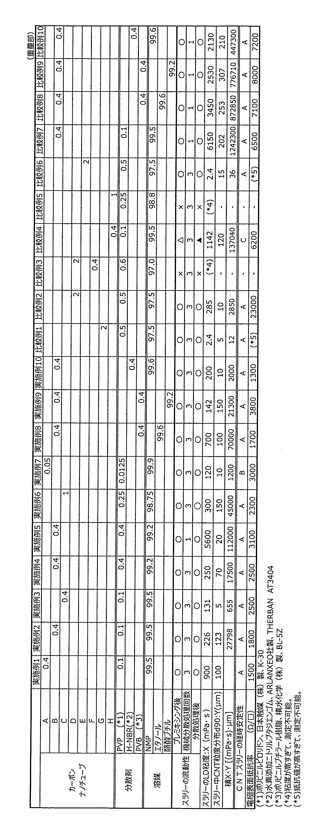
特に、本発明の範囲内である実施例1~10のカーボンナノチューブスラリーは、プレミキシングを行った後及びペイントシェーカーを用いた機械分散処理の後のビーズの動きも良好であり、操作性の良好なカーボンナノチューブスラリーが得られることが確認された。
Claims (5)
- 少なくとも、カーボンナノチューブ、分散剤、及び非水系溶媒を含有し、
前記カーボンナノチューブが70m2/g~180m2/gのBET比表面積を有し、且つ、ラマン分光法におけるピーク強度比G/Dが1.0~2.5であるカーボンナノチューブスラリー。
(但し、前記ピーク強度比G/Dは、ラマンスペクトルにおいて、1570cm-1~1620cm-1の範囲にあるGバンド散乱光ピークの最大強度をG、1320cm-1~1370cm-1の範囲にあるDバンド散乱光ピークの最大強度Dとするとき、その比を表す) - 前記カーボンナノチューブが、繊維長30μm~1000μm、繊維幅3nm~20nmである請求項1に記載のカーボンナノチューブスラリー。
- 前記カーボンナノチューブの含有量が0.1質量%~3.0量%である請求項1に記載のカーボンナノチューブスラリー。
- 前記カーボンナノチューブを0.4質量%で、かつ、前記分散剤を前記非水系溶媒に前記カーボンナノチューブスラリーと同一濃度で分散した分散液試料について測定された、25℃、剪断速度38.3s-1における粘度をX(mPa・s)とし、当該カーボンナノチューブスラリーに含有されるカーボンナノチューブのd90粒度分布をY(μm)とするとき、XとYの積の値が30万[(mPa・s)・μm]以下であることを特徴とする、請求項1に記載のカーボンナノチューブスラリー。
- 少なくとも、請求項1~4のいずれか一項に記載のカーボンナノチューブスラリー、及び、活物質を含む電極用スラリー。
Priority Applications (3)
| Application Number | Priority Date | Filing Date | Title |
|---|---|---|---|
| CN202480041989.2A CN121399062A (zh) | 2023-07-06 | 2024-07-04 | 碳纳米管浆料和电极用浆料 |
| JP2025531597A JPWO2025009595A1 (ja) | 2023-07-06 | 2024-07-04 | |
| KR1020267003727A KR20260035242A (ko) | 2023-07-06 | 2024-07-04 | 카본 나노 튜브 슬러리 및 전극용 슬러리 |
Applications Claiming Priority (2)
| Application Number | Priority Date | Filing Date | Title |
|---|---|---|---|
| JP2023-111661 | 2023-07-06 | ||
| JP2023111661 | 2023-07-06 |
Publications (1)
| Publication Number | Publication Date |
|---|---|
| WO2025009595A1 true WO2025009595A1 (ja) | 2025-01-09 |
Family
ID=94171596
Family Applications (1)
| Application Number | Title | Priority Date | Filing Date |
|---|---|---|---|
| PCT/JP2024/024260 Ceased WO2025009595A1 (ja) | 2023-07-06 | 2024-07-04 | カーボンナノチューブスラリー及び電極用スラリー |
Country Status (4)
| Country | Link |
|---|---|
| JP (1) | JPWO2025009595A1 (ja) |
| KR (1) | KR20260035242A (ja) |
| CN (1) | CN121399062A (ja) |
| WO (1) | WO2025009595A1 (ja) |
Cited By (1)
| Publication number | Priority date | Publication date | Assignee | Title |
|---|---|---|---|---|
| WO2026079394A1 (ja) * | 2024-10-10 | 2026-04-16 | 日本ゼオン株式会社 | 二次電池電極用組成物セット、第1組成物、第2組成物、二次電池電極用組成物1、二次電池電極用組成物2、二次電池電極用組成物3、二次電池用電極および二次電池、ならびに、二次電池電極用組成物の製造方法 |
Citations (6)
| Publication number | Priority date | Publication date | Assignee | Title |
|---|---|---|---|---|
| JP2017024964A (ja) * | 2015-07-28 | 2017-02-02 | デンカ株式会社 | カーボンナノファイバー分散液およびそれを用いた透明導電膜、透明導電フィルム。 |
| JP2017206413A (ja) * | 2016-05-18 | 2017-11-24 | 戸田工業株式会社 | カーボンナノチューブとその製造方法、及びカーボンナノチューブ分散体 |
| JP2018534747A (ja) * | 2015-10-28 | 2018-11-22 | エルジー・ケム・リミテッド | 導電材分散液およびこれを用いて製造したリチウム二次電池 |
| JP2020011873A (ja) * | 2018-07-20 | 2020-01-23 | 東洋インキScホールディングス株式会社 | カーボンナノチューブ分散液およびその利用 |
| WO2020129872A1 (ja) * | 2018-12-17 | 2020-06-25 | レジノカラー工業株式会社 | カーボンナノチューブ分散液、及びその製造方法 |
| WO2023008949A1 (ko) * | 2021-07-29 | 2023-02-02 | 주식회사 엘지에너지솔루션 | 도전재 분산액, 이를 이용하여 제조된 전극 및 리튬 이차전지 |
-
2024
- 2024-07-04 CN CN202480041989.2A patent/CN121399062A/zh active Pending
- 2024-07-04 KR KR1020267003727A patent/KR20260035242A/ko active Pending
- 2024-07-04 WO PCT/JP2024/024260 patent/WO2025009595A1/ja not_active Ceased
- 2024-07-04 JP JP2025531597A patent/JPWO2025009595A1/ja active Pending
Patent Citations (6)
| Publication number | Priority date | Publication date | Assignee | Title |
|---|---|---|---|---|
| JP2017024964A (ja) * | 2015-07-28 | 2017-02-02 | デンカ株式会社 | カーボンナノファイバー分散液およびそれを用いた透明導電膜、透明導電フィルム。 |
| JP2018534747A (ja) * | 2015-10-28 | 2018-11-22 | エルジー・ケム・リミテッド | 導電材分散液およびこれを用いて製造したリチウム二次電池 |
| JP2017206413A (ja) * | 2016-05-18 | 2017-11-24 | 戸田工業株式会社 | カーボンナノチューブとその製造方法、及びカーボンナノチューブ分散体 |
| JP2020011873A (ja) * | 2018-07-20 | 2020-01-23 | 東洋インキScホールディングス株式会社 | カーボンナノチューブ分散液およびその利用 |
| WO2020129872A1 (ja) * | 2018-12-17 | 2020-06-25 | レジノカラー工業株式会社 | カーボンナノチューブ分散液、及びその製造方法 |
| WO2023008949A1 (ko) * | 2021-07-29 | 2023-02-02 | 주식회사 엘지에너지솔루션 | 도전재 분산액, 이를 이용하여 제조된 전극 및 리튬 이차전지 |
Cited By (1)
| Publication number | Priority date | Publication date | Assignee | Title |
|---|---|---|---|---|
| WO2026079394A1 (ja) * | 2024-10-10 | 2026-04-16 | 日本ゼオン株式会社 | 二次電池電極用組成物セット、第1組成物、第2組成物、二次電池電極用組成物1、二次電池電極用組成物2、二次電池電極用組成物3、二次電池用電極および二次電池、ならびに、二次電池電極用組成物の製造方法 |
Also Published As
| Publication number | Publication date |
|---|---|
| JPWO2025009595A1 (ja) | 2025-01-09 |
| KR20260035242A (ko) | 2026-03-12 |
| CN121399062A (zh) | 2026-01-23 |
Similar Documents
| Publication | Publication Date | Title |
|---|---|---|
| JP7688470B2 (ja) | カーボンナノチューブ分散組成物、およびそれを用いた樹脂組成物、電極膜、二次電池、車両 | |
| CN102576873B (zh) | 锂二次电池用正极活性物质材料、其制造方法及使用其的锂二次电池 | |
| JP2020536360A (ja) | 硫黄−炭素複合体、その製造方法及びこれを含むリチウム二次電池 | |
| WO2014141552A1 (ja) | 負極製造用ペーストの製造方法、リチウムイオン二次電池用負極の製造方法、リチウムイオン二次電池用負極およびリチウムイオン二次電池 | |
| CN104115311A (zh) | 二次电池电极形成用组合物、二次电池电极以及二次电池 | |
| CN112334409A (zh) | 硫碳复合物和其制造方法 | |
| JP7568157B1 (ja) | カーボンナノチューブ、カーボンナノチューブ分散液、およびそれを用いた二次電池、ならびにカーボンナノチューブの製造方法 | |
| WO2025009595A1 (ja) | カーボンナノチューブスラリー及び電極用スラリー | |
| JP2019220401A (ja) | 電極用カーボンブラックスラリー及び電極形成用組成物 | |
| JP2022165797A (ja) | 下地層用炭素材料分散液、およびそれを用いた下地層用導電性組成物、蓄電デバイス用下地層付き集電体、蓄電デバイス用電極、蓄電デバイス | |
| JP7822140B2 (ja) | カーボンナノチューブ分散液、これを用いた導電ペースト、二次電池用電極ペースト、二次電池用電極、及び、二次電池 | |
| JP2025025776A (ja) | 電極形成用スラリー | |
| JP2019192540A (ja) | リチウムイオン二次電池用電極製造用ペーストの製造方法、リチウムイオン二次電池用電極の製造方法、リチウムイオン二次電池用電極およびリチウムイオン二次電池 | |
| JP5824723B2 (ja) | リチウム二次電池用正極活物質材料の製造方法、及びそれを用いたリチウム二次電池 | |
| WO2025009594A1 (ja) | カーボンナノチューブスラリー及び電極用スラリー | |
| JP7723860B1 (ja) | 全固体二次電池用電極組成物、該組成物を用いてなる電極スラリー、電極電池、及び該組成物の製造方法 | |
| JP7457227B1 (ja) | 二次電池電極用複合物 | |
| JP2024176001A (ja) | グラフェン分散体 | |
| JP7390516B1 (ja) | 二次電池電極用複合物 | |
| WO2025173612A1 (ja) | 電極作製用カーボンナノチューブ分散液及び電極作製用スラリー | |
| WO2025211160A1 (ja) | 非水系カーボンナノチューブスラリー及び正極用分散体 | |
| JP2025084577A (ja) | 二次電池電極用複合物 | |
| WO2024053488A1 (ja) | 電池電極用黒鉛分散体 | |
| WO2026094592A1 (ja) | 溶剤系分散体用カーボンナノチューブ、溶剤系分散体、電極用スラリーおよび電極膜 | |
| WO2025005257A1 (ja) | 二次電池電極用複合物 |
Legal Events
| Date | Code | Title | Description |
|---|---|---|---|
| 121 | Ep: the epo has been informed by wipo that ep was designated in this application |
Ref document number: 24836107 Country of ref document: EP Kind code of ref document: A1 |
|
| ENP | Entry into the national phase |
Ref document number: 2025531597 Country of ref document: JP Kind code of ref document: A |
|
| WWE | Wipo information: entry into national phase |
Ref document number: 2025531597 Country of ref document: JP |
|
| ENP | Entry into the national phase |
Ref document number: 1020267003727 Country of ref document: KR Free format text: ST27 STATUS EVENT CODE: A-0-1-A10-A15-NAP-PA0105 (AS PROVIDED BY THE NATIONAL OFFICE) |
|
| WWE | Wipo information: entry into national phase |
Ref document number: 1020267003727 Country of ref document: KR |
|
| NENP | Non-entry into the national phase |
Ref country code: DE |
|
| WWP | Wipo information: published in national office |
Ref document number: 1020267003727 Country of ref document: KR |