WO2025009498A1 - 保護層付き電波散乱シート - Google Patents
保護層付き電波散乱シート Download PDFInfo
- Publication number
- WO2025009498A1 WO2025009498A1 PCT/JP2024/023731 JP2024023731W WO2025009498A1 WO 2025009498 A1 WO2025009498 A1 WO 2025009498A1 JP 2024023731 W JP2024023731 W JP 2024023731W WO 2025009498 A1 WO2025009498 A1 WO 2025009498A1
- Authority
- WO
- WIPO (PCT)
- Prior art keywords
- protective layer
- radio wave
- wave scattering
- scattering sheet
- dielectric constant
- Prior art date
- Legal status (The legal status is an assumption and is not a legal conclusion. Google has not performed a legal analysis and makes no representation as to the accuracy of the status listed.)
- Ceased
Links
Images




Classifications
-
- B—PERFORMING OPERATIONS; TRANSPORTING
- B32—LAYERED PRODUCTS
- B32B—LAYERED PRODUCTS, i.e. PRODUCTS BUILT-UP OF STRATA OF FLAT OR NON-FLAT, e.g. CELLULAR OR HONEYCOMB, FORM
- B32B7/00—Layered products characterised by the relation between layers; Layered products characterised by the relative orientation of features between layers, or by the relative values of a measurable parameter between layers, i.e. products comprising layers having different physical, chemical or physicochemical properties; Layered products characterised by the interconnection of layers
- B32B7/02—Physical, chemical or physicochemical properties
- B32B7/025—Electric or magnetic properties
-
- H—ELECTRICITY
- H01—ELECTRIC ELEMENTS
- H01Q—ANTENNAS, i.e. RADIO AERIALS
- H01Q15/00—Devices for reflection, refraction, diffraction or polarisation of waves radiated from an antenna, e.g. quasi-optical devices
- H01Q15/14—Reflecting surfaces; Equivalent structures
Definitions
- the present invention relates to a radio wave scattering sheet with a protective layer that covers the metal pattern exposed as the radio wave scattering surface of a radio wave scattering sheet with a metamaterial structure to improve its appearance and durability.
- radio waves in the 28 GHz frequency band are being used.
- radio waves have a high propagation attenuation and a high degree of directivity, so if there is an obstruction between the transmitting antenna and the receiving antenna, the radio waves from the transmitting antenna do not reach the receiving antenna, resulting in a significant deterioration in communication quality.
- a radio wave scattering sheet with a metamaterial structure that scatters reflected radio waves over a wide angle has been developed.
- Metamaterial radio wave scattering sheets include those designed to obtain a desired scattering pattern by processing a specific metal pattern on a dielectric substrate (see, for example, Non-Patent Document 1). Reflectarrays have also been developed that control the reflection phase of electromagnetic waves by changing the dimensions and shape of the reflecting elements to change the resonant frequency of each reflecting element, thereby controlling the incident and reflected directions of electromagnetic waves (see, for example, Patent Document 1). These radio wave scattering sheets and reflectarrays are attached to indoor walls, ceilings, etc., and by scattering the scattered waves on the surface (radio wave scattering surface) over a wide angle, it is possible for radio waves to reach areas that cannot be reached by ordinary metal plates, improving the quality of wireless communications for multiple terminals and moving terminals.
- the present invention aims to provide a radio wave scattering sheet with a protective layer that improves the appearance and durability of the radio wave scattering sheet while minimizing the impairment of the radio wave scattering properties.
- the present invention provides a radio wave scattering sheet with a protective layer, which includes a radio wave scattering sheet having a metamaterial structure that scatters electromagnetic waves in multiple directions when electromagnetic waves of a specific frequency band are received on a radio wave scattering surface having a specific metal pattern formed on a dielectric substrate, and a protective layer that covers the radio wave scattering surface of the radio wave scattering sheet to protect the metal pattern and has at least an opaque outer surface, the protective layer being characterized in that the thickness of the protective layer that covers the radio wave scattering surface is in the range of 0.25 mm to 3.0 mm and has a relative dielectric constant in the range of 2.0 to 4.0.
- the protective layer may be made of a single material that covers the radio wave scattering surface to a thickness in the range of 0.25 mm to 2.0 mm and has a relative dielectric constant in the range of 2.0 to 3.0.
- the protective layer may have a two-layer structure consisting of a lower protective layer placed on the radio wave scattering surface and an upper protective layer placed on the lower protective layer, the total thickness of the lower protective layer and the upper protective layer may be in the range of 0.5 to 1.0 mm, and the overall relative dielectric constant of the lower protective layer and the upper protective layer combined may be in the range of 2.0 to 3.0.
- the radio wave scattering sheet with a protective layer according to the present invention can improve the appearance and durability of the radio wave scattering sheet by using the protective layer, while minimizing the decrease in the directional diffusion of the radio wave scattering sheet by 10% or less.
- FIG. 1(A) is a schematic vertical cross-sectional view of a radio wave scattering sheet with a protective layer according to a first embodiment
- Fig. 1(B) is a schematic vertical cross-sectional view of a radio wave scattering sheet with a protective layer according to a second embodiment
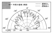
- FIG. 2 is a scattering characteristic diagram showing the scattering characteristics of a radio wave scattering sheet to which a commercially available wallpaper is attached as a protective layer.
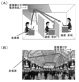
- Fig. 3A is an explanatory diagram showing an example of using the radio wave scattering sheet with a protective layer in an office
- Fig. 3B is an explanatory diagram showing an example of using the radio wave scattering sheet with a protective layer outdoors.
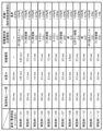
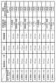
- FIG. 4 is a list showing the first examples (Example 1-01 to Example 1-12) performed for Evaluation 1.
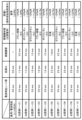
- FIG. 5 is a list showing the first comparative examples (Comparative Example 1-01 to Comparative Example 1-10) performed for Evaluation 1.
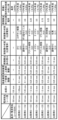
- FIG. 6 is a list showing the second examples (Example 2-01 to Example 2-09) performed for Evaluation 2.
- FIG. 7 is a list showing Examples 2-10 to 2-19 among the second comparative examples (Comparative Example 2-01 to Comparative Example 2-10) performed for Evaluation 2.
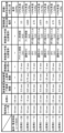
- FIG. 8 is a list showing Examples 3-01 to 3-08 among the third examples carried out for Evaluation 3.
- FIG. 9 is a list showing Examples 3-09 to 3-15 among the third examples carried out for Evaluation 3.
- FIG. 10 is a list showing Comparative Examples 3-01 to 3-07 among the third comparative examples performed for Evaluation 3.
- FIG. 11 is a list showing Comparative Examples 3-08 to 3-14 among the third comparative examples performed for Evaluation 3.
- Fig. 1(A) shows a schematic vertical cross-sectional view of a radio wave scattering sheet with a protective layer 11 of a first embodiment
- Fig. 1(B) shows a schematic vertical cross-sectional view of a radio wave scattering sheet with a protective layer 12 of a second embodiment.
- the radio wave scattering sheet 11 with protective layer of the first embodiment comprises a radio wave scattering sheet 1 consisting of a dielectric substrate 1a with a back metal plate 1b and a surface metal processed layer 1c on both sides thereof, a dielectric layer 2 as a protective layer covering the radio wave scattering surface 1d corresponding to the surface of the surface metal processed layer 1c of the radio wave scattering sheet 1, and an adhesive layer 3 provided on the outer surface (lower surface) of the back metal plate 1b for attaching the radio wave scattering sheet 1 to a wall surface, ceiling, etc.
- the radio wave scattering sheet 1 uses a glass epoxy board (grade FR4) with a thickness of about 0.68 [mm] and a relative dielectric constant of 4.5 as the dielectric board 1a, a metal film (e.g., copper foil) of about 60 [ ⁇ m] formed on one side of the dielectric board 1a as the back metal plate 1b, and a surface metal processing layer 1c in which a specific metal pattern is formed by processing the metal film (e.g., copper foil) of about 60 [ ⁇ m] formed on the other side of the dielectric board 1a by etching or the like.
- a glass epoxy board grade FR4 with a thickness of about 0.68 [mm] and a relative dielectric constant of 4.5
- a metal film e.g., copper foil
- a surface metal processing layer 1c in which a specific metal pattern is formed by processing the metal film (e.g., copper foil) of about 60 [ ⁇ m] formed on the other side of the dielectric board 1a by etching or the like.
- This radio wave scattering sheet 1 has a metamaterial structure that can scatter radio waves arriving at the radio wave scattering surface 1d from multiple directions over a wide angle by forming a patch structure in the surface metal processing layer 1c that combines areas with reflection phases of 0° and 180° within a unit unit surface (e.g., a surface of 180 [mm] x 180 [mm]).
- the radio wave scattering sheet 1 of this embodiment was designed to match electromagnetic waves in the 28 [GHz] band selected as a specific frequency band.
- the total thickness of the radio wave scattering sheet 1, which includes the dielectric substrate 1a, the back metal plate 1b, and the surface metal processing layer 1c, is approximately 0.8 mm.
- the dielectric layer 2 may be formed by applying a coating agent or the like to the radio wave scattering surface 1d of the radio wave scattering sheet 1 in a uniform thickness, or by attaching a plate-shaped material made of an adhesive material to the radio wave scattering surface 1d of the radio wave scattering sheet 1.
- a coating agent or the like to the radio wave scattering surface 1d of the radio wave scattering sheet 1 in a uniform thickness, or by attaching a plate-shaped material made of an adhesive material to the radio wave scattering surface 1d of the radio wave scattering sheet 1.
- the surface of the dielectric layer 2 is not limited to a single color, and may be made up of multiple colors. For example, if multiple types of coating agents with the same relative dielectric constant but different colors are used, a multi-colored pattern can be expressed on the surface of the dielectric layer 2.
- the thickness and dielectric constant of the dielectric layer 2 (hereinafter, the relative dielectric constant expressed as the ratio to the dielectric constant of a vacuum) play a significant role in the scattering characteristics of the radio wave scattering sheet with protective layer 11.
- the radio wave scattering sheet 12 with protective layer of the second embodiment includes a dielectric layer 2' as a protective layer covering the radio wave scattering surface 1d corresponding to the surface of the surface metal processing layer 1c of the radio wave scattering sheet 1, and an adhesive layer 3 provided on the outer surface of the back metal plate 1b to attach the radio wave scattering sheet 1 to a wall surface, ceiling, etc.
- the dielectric layer 2' has a two-layer structure in which an adhesive layer 2b as a lower protective layer is provided on the lower surface of the surface layer 2a as an upper protective layer, and is attached to the radio wave scattering surface 1d of the radio wave scattering sheet 1 by the viscosity of the adhesive layer 2b.
- the material forming the surface layer 2a of the dielectric layer 2' is opaque, the surface metal processing layer 1c will not be visible, so the appearance of the radio wave scattering sheet 12 with protective layer can be improved.
- the materials of the surface layer 2a and adhesive layer 2b can be selected in various ways, but it is considered that the thickness of the entire protective layer (dielectric layer 2') and the dielectric constant of the entire protective layer (dielectric layer 2') are not little involved in the scattering characteristics of the radio wave scattering sheet 12 with protective layer.
- the protective layer is not limited to two layers, but may be a multi-layer structure of three or more layers, including a printing layer and a surface coating layer.
- Figure 2 shows the scattering characteristics of radio wave scattering sheet 12 with protective layer, which is made by attaching a commercially available wallpaper, for example, a vinyl chloride resin sheet with a thickness of about 0.4 [mm] (estimated relative dielectric constant: 3.0) as a protective layer to radio wave scattering sheet 1.
- a commercially available wallpaper for example, a vinyl chloride resin sheet with a thickness of about 0.4 [mm] (estimated relative dielectric constant: 3.0) as a protective layer to radio wave scattering sheet 1.
- the scattering characteristics of radio wave scattering sheet 1 alone are shown by a dashed line.
- the scattering pattern of radio wave scattering sheet 12 with protective layer does not completely match the scattering pattern of radio wave scattering sheet 1 without wallpaper, similar results were obtained, and it was experimentally confirmed that radio wave scattering sheet 1 can fully function even when wallpaper is attached as a protective layer to radio wave scattering surface 1d.
- radio wave scattering sheets 11 and 12 with protective layer can be attached to the wall or ceiling in an office as shown in Figure 3 (A), or by placing radio wave scattering sheets 11 and 12 with protective layer outdoors where there is a shield as shown in Figure 3 (B), radio waves in the 28 [GHz] band transmitted from the transmission source can be delivered over a wide area, improving communication quality.
- the radio wave scattering sheets 11 and 12 with protective layers can suppress deterioration over time by protecting the surface metal processing layer 1c of the radio wave scattering sheet 1 with the dielectric layers 2 and 2', and can improve their appearance so that they blend in with the surrounding environment.
- Figure 4 shows the first example (Example 1-01 to Example 1-12) performed to evaluate the degree of change in directional diffusion as the radio wave scattering sheet 11 with a protective layer.
- the thickness and relative dielectric constant of the protective layer formed on the radio wave scattering surface 1d of the radio wave scattering sheet 1 with a thickness of 0.8 [mm] described above are changed, and it is evaluated whether the change is within -10% or worse than -10% compared to the directional diffusion of the reference radio wave scattering sheet 1 (hereinafter referred to as Evaluation 1).
- Figure 5 shows the first comparative examples (Comparative Example 1-01 to Comparative Example 1-10) where the change in directional diffusion is worse than -10%.
- Example 1-01 a 0.25 mm thick polyvinyl chloride (relative dielectric constant: 3.0) protective layer is provided so that the total thickness of the radio wave scattering sheet 11 with protective layer is 1.05 mm.
- the directional diffusion degree is +3.7%, which is an increase from the directional diffusion degree of the reference radio wave scattering sheet 1, so that the evaluation 1 is within -10%.
- the directional diffusion degree of the radio wave scattering sheet 11 with protective layer provided with protective layer is improved compared to the directional diffusion degree of the reference radio wave scattering sheet 1.
- radio wave scattering sheet 11 with protective layer provided with a protective layer of appropriate conditions, it is possible that the directional diffusion degree can be improved more than that of the radio wave scattering sheet 1 alone. This will be verified in Examples 2 and 3 described later.
- Example 1-02 a fluororesin (dielectric constant 4.0) with a thickness of 0.5 mm was provided as a protective layer so that the total thickness of the radio wave scattering sheet 11 with protective layer was 1.3 mm.
- the change in directional diffusion was -8.3%, which was a decrease of less than -10% compared to the directional diffusion of the reference radio wave scattering sheet 1, so that the evaluation 1 was within -10%.
- Example 1-03 a fluororesin (dielectric constant 4.0) with a thickness of 1.0 mm was provided as a protective layer so that the total thickness of the radio wave scattering sheet 11 with protective layer was 1.8 mm.
- the change in directional diffusion was -8.7%, which was a decrease of less than -10% compared to the directional diffusion of the reference radio wave scattering sheet 1, so that the evaluation 1 was within -10%. From the results of Examples 1-01 to 1-03, it can be seen that if the thickness of the protective layer is in the range of 0.25 mm to 1.0 mm and the relative dielectric constant of the protective layer is in the range of 3.0 to 4.0, the change in directional diffusion of the reference radio wave scattering sheet 1 is within -10%.
- Example 1-04 a 1.5 mm thick nylon (dielectric constant: 3.5) protective layer was provided so that the total thickness of the radio wave scattering sheet 11 with protective layer was 2.3 mm.
- the change in directional diffusion was -2.0%, which was a decrease of less than -10% compared to the directional diffusion of the reference radio wave scattering sheet 1, so that the evaluation 1 was within -10%.
- Example 1-05 a 1.5 mm thick fluororesin (dielectric constant: 4.0) protective layer was provided so that the total thickness of the radio wave scattering sheet 11 with protective layer was 2.3 mm.
- the change in directional diffusion was -1.1%, which was a decrease of less than -10% compared to the directional diffusion of the reference radio wave scattering sheet 1, so that the evaluation 1 was within -10%. From the results of Examples 1-04 to 1-05, it can be seen that if the thickness of the protective layer is 1.5 mm and the relative dielectric constant of the protective layer is within the range of 3.5 to 4.0, the change in directional diffusion degree of the reference radio wave scattering sheet 1 is within -10%.
- Example 1-06 a 2.0 mm thick nylon (dielectric constant 3.5) was provided as a protective layer so that the total thickness of the radio wave scattering sheet 11 with protective layer was 2.8 mm.
- the change in directional diffusion was -2.8%, which was a decrease of less than -10% compared to the directional diffusion of the reference radio wave scattering sheet 1, so that the evaluation 1 was within -10%.
- a 2.0 mm thick fluororesin (dielectric constant 4.0) was provided as a protective layer so that the total thickness of the radio wave scattering sheet 11 with protective layer was 2.8 mm.
- the change in directional diffusion was -4.8%, which was a decrease of less than -10% compared to the directional diffusion of the reference radio wave scattering sheet 1, so that the evaluation 1 was within -10%. From the results of Examples 1-06 to 1-07, it can be seen that if the thickness of the protective layer is 2.0 mm and the relative dielectric constant of the protective layer is within the range of 3.5 to 4.0, the change in directional diffusion of the reference radio wave scattering sheet 1 is within -10%.
- Example 1-08 a 2.5 mm thick paper (dielectric constant 2.0) was provided as a protective layer so that the total thickness of the radio wave scattering sheet 11 with protective layer was 3.3 mm.
- the change in directional diffusion was -4.5%, which was a decrease of less than -10% compared to the directional diffusion of the reference radio wave scattering sheet 1, so that the evaluation 1 was within -10%.
- a 2.5 mm thick epoxy resin (dielectric constant 2.5) was provided as a protective layer so that the total thickness of the radio wave scattering sheet 11 with protective layer was 3.3 mm.
- the change in directional diffusion was -5.2%, which was a decrease of less than -10% compared to the directional diffusion of the reference radio wave scattering sheet 1, so that the evaluation 1 was within -10%. From the results of Examples 1-08 to 1-09, it can be seen that if the thickness of the protective layer is 2.5 mm and the relative dielectric constant of the protective layer is within the range of 2.0 to 2.5, the change in directional diffusion of the reference radio wave scattering sheet 1 is within -10%.
- Example 1-10 a 3.0 mm thick paper (relative dielectric constant 2.0) was provided as a protective layer so that the total thickness of the radio wave scattering sheet 11 with protective layer was 3.8 mm.
- the change in directional diffusion was -9.1%, which was a decrease of less than -10% compared to the directional diffusion of the reference radio wave scattering sheet 1, so that the evaluation 1 was within -10%.
- a 3.0 mm thick polyvinyl chloride (relative dielectric constant 3.0) was provided as a protective layer so that the total thickness of the radio wave scattering sheet 11 with protective layer was 3.8 mm.
- the change in directional diffusion was -5%, which was a decrease of less than -10% compared to the directional diffusion of the reference radio wave scattering sheet 1, so that the evaluation 1 was within -10%.
- a fluororesin (dielectric constant 4.0) with a thickness of 3.0 mm was provided as a protective layer so that the total thickness of the radio wave scattering sheet 11 with protective layer was 3.8 mm.
- the change in directional diffusion was -1%, which was a decrease of less than -10% compared to the directional diffusion of the reference radio wave scattering sheet 1, so the evaluation was within -10%.
- Comparative Example 1-01 a 0.5 mm thick furan resin (relative dielectric constant 4.5) was provided as a protective layer so that the total thickness of the radio wave scattering sheet 11 with protective layer was 1.3 mm.
- the change in directional diffusion was -20%, which is a decrease of more than -10% compared to the directional diffusion of the reference radio wave scattering sheet 1, so that Evaluation 1 is outside the -10% range.
- Comparative Example 1-02 a 0.5 mm thick polyurethane (relative dielectric constant 5.0) was provided as a protective layer so that the total thickness of the radio wave scattering sheet 11 with protective layer was 1.3 mm.
- the change in directional diffusion was -22%, which is a decrease of more than -10% compared to the directional diffusion of the reference radio wave scattering sheet 1, so that Evaluation 1 is outside the -10% range. From the results of these comparative examples 1-01 and 1-02, it can be seen that even if the thickness of the protective layer is 0.5 mm, if the relative dielectric constant of the protective layer is in the range of 4.5 to 5.0, the change in directional diffusion rate of the reference radio wave scattering sheet 1 will be less than -10%.
- Comparative Example 1-03 a 1.0 mm thick glass epoxy (dielectric constant 4.2) was provided as a protective layer so that the total thickness of the radio wave scattering sheet 11 with protective layer was 1.8 mm.
- the change in directional diffusion was -11.3%, which was a decrease of more than -10% compared to the directional diffusion of the reference radio wave scattering sheet 1, so that Evaluation 1 was outside the -10% range.
- Comparative Example 1-04 a 1.0 mm thick furan resin (dielectric constant 4.5) was provided as a protective layer so that the total thickness of the radio wave scattering sheet 11 with protective layer was 1.8 mm.
- the directional diffusion was -12.1%, which was a decrease of more than -10% compared to the directional diffusion of the reference radio wave scattering sheet 1, so that Evaluation 1 was outside the -10% range.
- a 1.0 mm thick polyurethane dielectric constant 5.0
- the change in directional diffusion was -13.1%, which is a decrease of more than -10% compared to the directional diffusion of the reference radio wave scattering sheet 1, so Evaluation 1 is outside the -10% range.
- Comparative Example 1-06 a 1.5 mm thick layer of gypsum (dielectric constant 5.5) was provided as a protective layer so that the total thickness of the radio wave scattering sheet 11 with protective layer was 2.3 mm.
- the change in directional diffusion was -16.7%, which is a decrease of more than -10% compared to the directional diffusion of the reference radio wave scattering sheet 1, so Evaluation 1 is outside the -10% range. From the results of Comparative Example 1-06, it can be seen that even if the protective layer is 1.5 mm thick, if the protective layer has a dielectric constant of 5.5, the change in directional diffusion will be less than -10% compared to the reference radio wave scattering sheet 1.
- Comparative Example 1-07 a 2.0 mm thick glass epoxy (dielectric constant 4.2) was provided as a protective layer so that the total thickness of the radio wave scattering sheet 11 with protective layer was 2.8 mm.
- the change in directional diffusion was -10.9%, which is a decrease of more than -10% compared to the directional diffusion of the reference radio wave scattering sheet 1, so that Evaluation 1 is outside the -10% range.
- a 2.0 mm thick furan resin (dielectric constant 4.5) was provided as a protective layer so that the total thickness of the radio wave scattering sheet 11 with protective layer was 2.8 mm.
- the change in directional diffusion was -10.1%, which is a decrease of more than -10% compared to the directional diffusion of the reference radio wave scattering sheet 1, so that Evaluation 1 is outside the -10% range.
- a 2.0 mm thick polyurethane dielectric constant 5.0
- the change in directional diffusion was -13.5%, which is a decrease of more than -10% compared to the directional diffusion of the reference radio wave scattering sheet 1, so Evaluation 1 is outside the -10% range.
- Comparative Example 1-10 a 3.0 mm thick plaster (dielectric constant 5.5) was provided as a protective layer so that the total thickness of the radio wave scattering sheet 11 with protective layer was 3.8 mm.
- the change in directional diffusion was -14.7%, which is a decrease of more than -10% compared to the directional diffusion of the reference radio wave scattering sheet 1, so Evaluation 1 is outside the -10% range. From the results of Comparative Example 1-10, it can be seen that when the protective layer is 3.0 mm thick and has a dielectric constant of 5.5, the change in directional diffusion is less than -10% compared to the reference radio wave scattering sheet 1.
- the radio wave scattering sheet 11 with a protective layer in which the dielectric layer 2 that meets the above conditions is provided as a protective layer can achieve a directional diffusion degree close to that when the radio wave scattering sheet 1 is used alone, and can contribute to improving communication quality not only in the 28 GHz band but also in microwaves and millimeter waves.
- the radio wave scattering sheet 11 with a protective layer can suppress deterioration over time by protecting the surface metal processing layer 1c of the radio wave scattering sheet 1 with the dielectric layer 2, and can improve its appearance so that it blends in with the surrounding environment.
- Example 1 only shows the radio wave scattering sheet 11 with protective layer using a single dielectric layer 2 as the protective layer, but also for the radio wave scattering sheet 12 with protective layer using two dielectric layers 2' as the protective layer, if the thickness covering the radio wave scattering surface 1d is in the range of 0.25 mm to 3.0 mm and the dielectric layer 2' has a relative dielectric constant in the range of 2.0 to 4.0, the change in directional diffusion degree is within -10% compared to the reference radio wave scattering sheet 1.
- the upper limit of the thickness of the dielectric layer 2, at which the change in the directional diffusion degree of the reference radio wave scattering sheet 1 falls within -10%, is set to 3.0 [mm] is because it was determined taking into consideration the thickness of the coating agent used as the protective layer and the thickness of the actual wallpaper. If the thickness of the protective layer exceeds 3.0 [mm], the durability increases, but problems arise in terms of weight, etc., making it inconvenient to handle the radio wave scattering sheets 11, 12 with protective layer, and in order to safely attach the radio wave scattering sheets 11, 12 with protective layer to a wall or ceiling, it becomes necessary to provide an adhesive layer 3 with very strong adhesive properties, which impairs practicality. Therefore, considering the realistic thickness range of the protective layer, it was determined that it is appropriate to set the upper limit of the thickness of the protective layer provided on the radio wave scattering sheet 1 to 3.0 [mm].
- Example 2-01 a 0.25 mm thick paper (relative dielectric constant 2.0) was provided as a protective layer so that the total thickness of the radio wave scattering sheet 11 with protective layer was 1.05 mm. The change in directional diffusion was +11.1%, so that the evaluation 2 was 1.0 or more.
- Example 2-02 a 0.25 mm thick polyvinyl chloride (relative dielectric constant 3.0) was provided as a protective layer so that the total thickness of the radio wave scattering sheet 11 with protective layer was 1.05 mm. The directional diffusion was +3.7%, so that the evaluation 2 was 1.0 or more.
- Example 2-03 a 0.5 mm thick epoxy resin (relative dielectric constant 2.5) was provided as a protective layer so that the total thickness of the radio wave scattering sheet 11 with protective layer was 1.3 mm.
- the directional diffusion was +13.8%, so that the evaluation 2 was 1.0 or more. From the results of Examples 2-01 to 2-03, it can be seen that if the thickness of the protective layer is in the range of 0.25 mm to 0.5 mm and the relative dielectric constant of the protective layer is in the range of 2.0 to 3.0, the directional diffusion degree is increased to above that of the reference radio wave scattering sheet 1, and the radio wave scattering characteristics are improved.
- Example 2-06 a 1.0 mm thick polyvinyl chloride (dielectric constant 3.0) was provided as a protective layer so that the total thickness of the radio wave scattering sheet 11 with protective layer was 1.8 mm.
- the directional diffusion degree was +12.0%, so the evaluation 2 was 1.0 or more. From the results of Examples 2-04 to 2-06, it can be seen that if the thickness of the protective layer is 1.0 [mm] and the relative dielectric constant of the protective layer is within the range of 2.0 to 3.0, the directional diffusion degree is increased to above that of the reference radio wave scattering sheet 1, and the radio wave scattering characteristics are improved.
- Example 2-07 a 1.5 mm thick paper (dielectric constant 2.0) was provided as a protective layer so that the total thickness of the radio wave scattering sheet 11 with protective layer was 2.3 mm.
- the directional diffusion degree was +17.4%, so the evaluation 2 was 1.0 or more.
- Example 2-08 a 1.5 mm thick epoxy resin (dielectric constant 2.5) was provided as a protective layer so that the total thickness of the radio wave scattering sheet 11 with protective layer was 2.3 mm.
- the directional diffusion degree was +10.0%, so the evaluation 2 was 1.0 or more.
- Example 2-09 a 2.0 mm thick paper (dielectric constant 2.0) was provided as a protective layer so that the total thickness of the radio wave scattering sheet 11 with protective layer was 2.8 mm.
- the directional diffusion degree was +10.4%, so the evaluation 2 was 1.0 or more. From the results of Examples 2-07 to 2-09, it can be seen that if the thickness of the protective layer is in the range of 1.5 mm to 2.0 mm and the relative dielectric constant of the protective layer is in the range of 2.0 to 2.5, the directional diffusion degree is increased to above that of the reference radio wave scattering sheet 1, and the radio wave scattering characteristics are improved.
- Comparative Example 2-01 a 0.5 mm thick fluororesin (dielectric constant 4.0) was provided as a protective layer so that the total thickness of the radio wave scattering sheet 11 with protective layer was 1.3 mm. The directional diffusion degree was -3.8%, so the evaluation 2 was less than 1.0.
- Comparative Example 2-02 a 1.0 mm thick soft PVC resin (dielectric constant 3.3) was provided as a protective layer so that the total thickness of the radio wave scattering sheet 11 with protective layer was 1.8 mm. The directional diffusion degree was -2.5%, so the evaluation 2 was less than 1.0.
- Comparative Example 2-03 a 1.0 mm thick nylon (dielectric constant 3.5) was provided as a protective layer so that the total thickness of the radio wave scattering sheet 11 with protective layer was 1.8 mm.
- the directional diffusion degree was -4.5%, so the evaluation 2 was less than 1.0. From the results of these comparative examples 2-01 to 2-03, it can be seen that even if the thickness of the protective layer is in the range of 0.5 mm to 1.0 mm, if the relative dielectric constant of the protective layer is in the range of 3.3 to 4.0, the directional diffusion degree is reduced compared to the reference radio wave scattering sheet 1, and the radio wave scattering characteristics are degraded.
- Comparative Example 2-04 a 1.5 mm thick soft PVC resin (dielectric constant: 3.3) was provided as a protective layer so that the total thickness of the radio wave scattering sheet 11 with protective layer was 2.3 mm.
- the directional diffusion degree was -0.8%, so the evaluation 2 was less than 1.0.
- Comparative Example 2-05 a 1.5 mm thick nylon (dielectric constant: 3.5) was provided as a protective layer so that the total thickness of the radio wave scattering sheet 11 with protective layer was 2.3 mm.
- the directional diffusion degree was -4.4%, so the evaluation 2 was less than 1.0.
- Comparative Example 2-06 a 2.0 mm thick nylon (dielectric constant: 3.5) protective layer was provided so that the total thickness of the radio wave scattering sheet 11 with protective layer was 2.8 mm. The directional diffusion degree was -2.8%, so the evaluation 2 was less than 1.0.
- Comparative Example 2-07 a 2.0 mm thick fluororesin (dielectric constant: 4.0) protective layer was provided so that the total thickness of the radio wave scattering sheet 11 with protective layer was 2.8 mm. The directional diffusion degree was -4.8%, so the evaluation 2 was less than 1.0.
- Comparative Example 2-08 a 2.5 mm thick paper (relative dielectric constant 2.0) was provided as a protective layer so that the total thickness of the radio wave scattering sheet 11 with protective layer was 3.3 mm.
- the directional diffusion degree was -4.5%, so the evaluation 2 was less than 1.0.
- Comparative Example 2-09 a 2.5 mm thick epoxy resin (relative dielectric constant 2.5) was provided as a protective layer so that the total thickness of the radio wave scattering sheet 11 with protective layer was 3.3 mm.
- the directional diffusion degree was -5.2%, so the evaluation 2 was less than 1.0.
- Comparative Example 2-10 a 2.5 mm thick polyvinyl chloride (relative dielectric constant 3.0) was provided as a protective layer so that the total thickness of the radio wave scattering sheet 11 with protective layer was 3.3 mm.
- the directional diffusion degree was -6.1%, so the evaluation 2 was less than 1.0. From the results of these comparative examples 2-08 to 10, it can be seen that when the thickness of the protective layer is 2.5 mm, even if the relative dielectric constant of the protective layer is in the range of 2.0 to 3.0, the directional diffusion degree is reduced compared to the reference radio wave scattering sheet 1, and the radio wave scattering characteristics are degraded.
- the dielectric layer 2 as a protective layer can obtain a directional diffusion degree equal to or greater than that of the reference radio wave scattering sheet 1 if the thickness covering the radio wave scattering surface 1d is in the range of 0.25 mm to 2.0 mm and the relative dielectric constant is in the range of 2.0 to 3.0. Therefore, the radio wave scattering sheet 11 with protective layer in which the dielectric layer 2 that meets the above conditions is provided as a protective layer can achieve a directional diffusion degree equal to or greater than that of the radio wave scattering sheet 1 used alone, and can therefore contribute greatly to improving communication quality not only in the 28 GHz band but also in microwaves and millimeter waves.
- radio wave scattering sheet 12 with a protective layer using a dielectric layer 2' as a protective layer consisting of two layers, a surface layer 2a and an adhesive layer 2b a third example (Example 3-01 to Example 3-15) performed to evaluate the improvement rate of the directional diffusion degree is shown in Figures 8 and 9.
- the radio wave scattering sheet 12 with a protective layer of the second embodiment described above can finely change the thickness of the entire protective layer and the relative dielectric constant of the entire protective layer by combining various materials of the surface layer 2a and the adhesive layer 2b.
- the thickness of the entire protective layer formed on the radio wave scattering surface 1d of the radio wave scattering sheet 1 with a thickness of 0.8 [mm] described above and the relative dielectric constant of the entire protective layer are changed, and it is evaluated whether an improvement rate of 10% or more is obtained (+10% or more) from the directional diffusion degree of the reference radio wave scattering sheet 1 (reference value ⁇ 0%) or whether the improvement rate remains less than 10% (less than +10%) (hereinafter referred to as Evaluation 3).
- the third comparative examples (Comparative Example 3-01 to Comparative Example 3-14) with an improvement rate of directional diffusion of less than +10% are shown in Figures 10 and 11.
- Example 3-01 a 0.5 mm thick glue (dielectric constant 2.0) was used as the adhesive layer and a 0.5 mm thick paper (dielectric constant 2.0) was used as the surface layer so that the total thickness of the radio wave scattering sheet 12 with protective layer was 1.8 mm, the overall thickness of the protective layer was 1.0 mm, and the overall dielectric constant of the protective layer was 2.0.
- the improvement rate of the directional diffusion degree was +11.4%, so the evaluation 3 was +10% or more.
- Example 3-02 a 0.5 mm thick glue (dielectric constant 2.0) was used as the adhesive layer and a 0.5 mm thick epoxy resin (dielectric constant 2.5) was used as the surface layer so that the total thickness of the radio wave scattering sheet 12 with protective layer was 1.8 mm, the overall thickness of the protective layer was 1.0 mm, and the overall dielectric constant of the protective layer was 2.25.
- the improvement rate of the directional diffusion rate is +18.3%, so that the evaluation 3 is +10% or more.
- Example 3-03 a 0.25 mm thick starch paste (relative dielectric constant 2.5) is provided as an adhesive layer, and a 0.75 mm thick epoxy resin (relative dielectric constant 2.5) is provided as a surface layer so that the total thickness of the radio wave scattering sheet 12 with protective layer is 1.8 mm, and the overall thickness of the protective layer is 1.0 mm and the overall dielectric constant of the protective layer is 2.5.
- the improvement rate of the directional diffusion rate is +19.7%, so that the evaluation 3 is +10% or more.
- the protective layer-attached radio wave scattering sheet 12 has a total thickness of 1.8 mm, and is provided with an adhesive layer of 0.25 mm thick acrylic resin (dielectric constant: 3.0) and a surface layer of 0.75 mm thick epoxy resin (dielectric constant: 2.5), with the protective layer having a total thickness of 1.0 mm and a total dielectric constant of 2.625.
- the improvement rate of the directional diffusion degree is +17.9%, so that the evaluation 3 is +10% or more.
- the protective layer-attached radio wave scattering sheet 12 has a total thickness of 1.8 mm, and is provided with an adhesive layer of 0.5 mm thick starch paste (dielectric constant: 2.5) and a surface layer of 0.5 mm thick polyvinyl chloride (dielectric constant: 3.0), with the protective layer having a total thickness of 1.0 mm and a total dielectric constant of 2.75. Since the improvement rate of the directional diffusion rate is +20.4%, the evaluation 3 is +10% or more.
- Example 3-06 an acrylic resin (relative dielectric constant 3.0) having a thickness of 0.5 [mm] is provided as an adhesive layer, and an epoxy resin (relative dielectric constant 2.5) having a thickness of 0.5 [mm] is provided as a surface layer so that the total thickness of the radio wave scattering sheet 12 with protective layer is 1.8 [mm], and the thickness of the entire protective layer is 1.0 [mm] and the relative dielectric constant of the entire protective layer is 2.75. Since the improvement rate of the directional diffusion rate is +16.8%, the evaluation 3 is +10% or more.
- Example 3-08 a 0.25 mm thick acrylic resin (dielectric constant: 3.0) was used as an adhesive layer, and a 0.75 mm thick polyvinyl chloride (dielectric constant: 3.0) was used as a surface layer, so that the total thickness of the radio wave scattering sheet 12 with protective layer was 1.8 mm, the total thickness of the protective layer was 1.0 mm, and the total dielectric constant of the protective layer was 3.0.
- the improvement rate of the directional diffusion rate is +12.0%, so the evaluation 3 is +10% or more.
- Example 3-09 a 0.25 mm thick glue (dielectric constant 2.0) was used as the adhesive layer and a 0.25 mm thick paper (dielectric constant 2.0) was used as the surface layer so that the total thickness of the radio wave scattering sheet 12 with protective layer was 1.3 mm, the overall thickness of the protective layer was 0.5 mm, and the overall dielectric constant of the protective layer was 2.0.
- the improvement rate of the directional diffusion degree was +11.8%, so the evaluation 3 was +10% or more.
- Example 3-10 a 0.25 mm thick glue (dielectric constant 2.0) was used as the adhesive layer and a 0.25 mm thick epoxy resin (dielectric constant 2.5) was used as the surface layer so that the total thickness of the radio wave scattering sheet 12 with protective layer was 1.3 mm, the overall thickness of the protective layer was 0.5 mm, and the overall dielectric constant of the protective layer was 2.25.
- the improvement rate of the directional diffusion rate is +10.5%, so that the evaluation 3 is +10% or more.
- Example 3-11 a 0.25 mm thick glue (relative dielectric constant 2.0) is provided as an adhesive layer, and a 0.25 mm thick polyvinyl chloride (relative dielectric constant 3.0) is provided as a surface layer so that the total thickness of the radio wave scattering sheet 12 with protective layer is 1.3 mm, and the overall thickness of the protective layer is 0.5 mm and the overall dielectric constant of the protective layer is 2.5.
- the improvement rate of the directional diffusion rate is +12.6%, so that the evaluation 3 is +10% or more.
- the protective layer-attached radio wave scattering sheet 12 has a total thickness of 1.3 mm, and is provided with a 0.25 mm thick starch paste (dielectric constant: 2.5) adhesive layer and a 0.25 mm thick paper (dielectric constant: 2.5) surface layer, with the protective layer having a total thickness of 0.5 mm and a total dielectric constant of 2.5.
- the improvement rate of the directional diffusion is +11.4%, so that the evaluation 3 is +10% or more.
- the protective layer-attached radio wave scattering sheet 12 has a total thickness of 1.3 mm, and is provided with a 0.25 mm thick starch paste (dielectric constant: 2.5) adhesive layer and a 0.25 mm thick polyvinyl chloride (dielectric constant: 3.0) surface layer, with the protective layer having a total thickness of 0.5 mm and a total dielectric constant of 2.75.
- the improvement rate of the directional diffusion rate is +14.9%, so the rating of 3 is +10% or more.
- the total thickness of the radio wave scattering sheet 12 with protective layer is 1.3 mm
- the adhesive layer is 0.25 mm thick acrylic resin (relative dielectric constant 3.0) and the surface layer is 0.25 mm thick paper (relative dielectric constant 2.5), so that the total thickness of the protective layer is 0.5 mm and the total dielectric constant of the protective layer is 2.75.
- the improvement rate of the directional diffusion degree is +14.1%, so that the evaluation 3 is +10% or more.
- the total thickness of the radio wave scattering sheet 12 with protective layer is 1.3 mm
- the adhesive layer is 0.25 mm thick acrylic resin (relative dielectric constant 3.0) and the surface layer is 0.25 mm thick polyvinyl chloride (relative dielectric constant 3.0), so that the total thickness of the protective layer is 0.5 mm and the total dielectric constant of the protective layer is 3.0.
- the improvement rate of the directional diffusion rate is +11.6%, so the evaluation 3 is +10% or more.
- Comparative Example 3-01 a 0.1 mm thick glue (dielectric constant: 2.0) was used as an adhesive layer and a 0.15 mm thick epoxy resin (dielectric constant: 2.5) was used as a surface layer so that the total thickness of the radio wave scattering sheet 12 with protective layer was 1.05 mm, the total thickness of the protective layer was 0.25 mm, and the total dielectric constant of the protective layer was 2.3.
- the improvement rate of the directional diffusion degree was +5.9%, so the evaluation 3 was less than +10%.
- Comparative Example 3-02 a 0.1 mm thick starch glue (dielectric constant: 2.5) was used as an adhesive layer and a 0.15 mm thick polyvinyl chloride (dielectric constant: 3.0) was used as a surface layer so that the total thickness of the radio wave scattering sheet 12 with protective layer was 1.05 mm, the total thickness of the protective layer was 0.25 mm, and the total dielectric constant of the protective layer was 2.6.
- the improvement rate of the directional diffusion rate is +9.8%, so the evaluation 3 is less than +10%.
- the protective layer-attached radio wave scattering sheet 12 has a total thickness of 1.3 mm, and is provided with an adhesive layer of 0.25 mm (dielectric constant: 3.0) and a surface layer of 0.25 mm (dielectric constant: 3.5).
- the protective layer has a total thickness of 0.50 mm and a total dielectric constant of 3.25.
- the improvement rate of the directional diffusion is +8.3%, so that the evaluation 3 is less than +10%.
- the protective layer-attached radio wave scattering sheet 12 has a total thickness of 1.3 mm, and is provided with an adhesive layer of 0.25 mm (dielectric constant: 3.5) and a surface layer of 0.25 mm (dielectric constant: 3.5).
- the protective layer has a total thickness of 0.50 mm and a total dielectric constant of 3.5.
- the improvement rate of the directional diffusion rate is +5.1%, so that the evaluation 3 is less than +10%.
- an acrylic resin (relative dielectric constant 3.0) having a thickness of 0.25 [mm] is provided as an adhesive layer, and a furan resin (relative dielectric constant 4.5) having a thickness of 0.25 [mm] is provided as a surface layer so that the total thickness of the radio wave scattering sheet 12 with protective layer is 1.3 [mm], and the thickness of the entire protective layer is 0.50 [mm], and the relative dielectric constant of the entire protective layer is 3.75.
- the improvement rate of the directional diffusion rate is +7.3%, so that the evaluation 3 is less than +10%. From the results of these Comparative Examples 3-03 to 3-05, it can be seen that even if the thickness of the entire protective layer is 0.5 [mm], if the relative dielectric constant of the entire protective layer is in the range of 3.25 to 3.75, it is not possible to obtain an improvement rate of 10% or more compared to the directional diffusion rate of the reference radio wave scattering sheet 1, and the improvement rate of the radio wave scattering characteristics is reduced to less than 10%.
- the protective layer-attached radio wave scattering sheet 12 has a total thickness of 1.8 mm, and is provided with a 0.5 mm thick starch paste (dielectric constant: 2.5) adhesive layer and a 0.5 mm thick fluororesin (dielectric constant: 4.0) surface layer, with the protective layer having a total thickness of 1.0 mm and a total dielectric constant of 3.25.
- the improvement rate of the directional diffusion is +9.4%, so that the evaluation 3 is less than +10%.
- the protective layer-attached radio wave scattering sheet 12 has a total thickness of 1.8 mm, and is provided with a 0.25 mm thick starch paste (dielectric constant: 2.5) adhesive layer and a 0.75 mm thick quartz (dielectric constant: 3.7) surface layer, with the protective layer having a total thickness of 1.0 mm and a total dielectric constant of 3.4. Since the improvement rate of the directional diffusion rate is +7.9%, the evaluation 3 is less than +10%.
- an acrylic resin having a thickness of 0.5 [mm] is provided as an adhesive layer
- a fluororesin having a thickness of 0.5 [mm] is provided as a surface layer so that the total thickness of the radio wave scattering sheet 12 with protective layer is 1.8 [mm], and the thickness of the entire protective layer is 1.0 [mm] and the relative dielectric constant of the entire protective layer is 3.5. Since the improvement rate of the directional diffusion rate is +2.0%, the evaluation 3 is less than +10%.
- Comparative Example 3-09 a 0.25 mm thick starch paste (dielectric constant: 2.5) was used as the adhesive layer, and a 0.75 mm thick fluororesin (dielectric constant: 4.0) was used as the surface layer so that the total thickness of the radio wave scattering sheet 12 with protective layer was 1.8 mm.
- the overall thickness of the protective layer was 1.0 mm, and the overall dielectric constant of the protective layer was 3.625. Since the improvement rate of the directional diffusion rate was +2.5%, the evaluation 3 was less than +10%.
- the protective layer-attached radio wave scattering sheet 12 has a total thickness of 2.3 mm, and is provided with a 0.5 mm thick glue (dielectric constant: 2.0) as an adhesive layer and a 1.0 mm thick polyvinyl chloride (dielectric constant: 3.0) as a surface layer, with the protective layer having a total thickness of 1.5 mm and a total dielectric constant of 2.75.
- the improvement rate of the directional diffusion is +5.6%, so that the evaluation 3 is less than +10%.
- the protective layer-attached radio wave scattering sheet 12 has a total thickness of 2.3 mm, and is provided with a 0.5 mm thick starch glue (dielectric constant: 2.5) as an adhesive layer and a 1.0 mm thick polyvinyl chloride (dielectric constant: 3.0) as a surface layer, with the protective layer having a total thickness of 1.5 mm and a total dielectric constant of 2.875.
- the improvement rate of the directional diffusion rate is +5.1%, so that the evaluation 3 is less than +10%.
- Comparative Example 3-12 a 0.25 mm thick starch paste (relative dielectric constant 2.5) is provided as an adhesive layer, and a 1.25 mm thick polyvinyl chloride (relative dielectric constant 3.0) is provided as a surface layer so that the total thickness of the radio wave scattering sheet 12 with protective layer is 2.3 mm, so that the thickness of the entire protective layer is 1.5 mm, and the relative dielectric constant of the entire protective layer is 2.9.
- the improvement rate of the directional diffusion rate is +3.6%, so that the evaluation 3 is less than +10%.
- Comparative Example 3-13 a 0.5 mm thick glue (dielectric constant: 2.0) was used as an adhesive layer and a 1.5 mm thick polyvinyl chloride (dielectric constant: 3.0) was used as a surface layer so that the total thickness of the radio wave scattering sheet 12 with protective layer was 2.8 mm, the overall thickness of the protective layer was 2.0 mm, and the overall dielectric constant of the protective layer was 2.75.
- the improvement rate of the directional diffusion degree was -5.8%, so the evaluation 3 was less than +10%.
- Comparative Example 3-14 a 0.5 mm thick starch glue (dielectric constant: 2.5) was used as an adhesive layer and a 1.5 mm thick polyvinyl chloride (dielectric constant: 3.0) was used as a surface layer so that the total thickness of the radio wave scattering sheet 12 with protective layer was 2.8 mm, the overall thickness of the protective layer was 2.0 mm, and the overall dielectric constant of the protective layer was 2.875.
- the improvement rate of the directional diffusion rate is -1.9%, so the evaluation 3 is less than +10%.
- a radio wave scattering sheet 11 with a protective layer that is provided with a dielectric layer 2' that meets the above conditions as a protective layer can achieve a directional diffusion degree equal to or greater than that when the radio wave scattering sheet 1 is used alone, and can therefore contribute greatly to improving communication quality not only in the 28 GHz band but also in microwaves and millimeter waves.
- Radio wave scattering sheet with protective layer (first embodiment) REFERENCE SIGNS LIST 1 Radio wave scattering sheet 1a Dielectric substrate 1b Back metal plate 1c Surface metal processing layer 1d Radio wave scattering surface 2 Dielectric layer 3 Adhesive layer 12 Radio wave scattering sheet with protective layer (second embodiment) 2' Dielectric layer 2a Surface layer 2b Adhesive layer
Landscapes
- Physics & Mathematics (AREA)
- Electromagnetism (AREA)
- Laminated Bodies (AREA)
- Aerials With Secondary Devices (AREA)
- Shielding Devices Or Components To Electric Or Magnetic Fields (AREA)
Abstract
電波散乱シートの見栄えと耐久性を向上させつつ、電波散乱特性を可能な限り阻害しない保護層を設けた保護層付き電波散乱シートを提供する。 電波散乱シート1の電波散乱面1dを誘電体層2により被覆することで、表面金属加工層1cを保護した保護層付き電波散乱シート11は、誘電体層2によって電波散乱シート1の見栄えと耐久性を向上させる。加えて、電波散乱面1dを覆う誘電体層2の厚さが0.25mm~3.0mmの範囲で、且つ、誘電体層2の比誘電率を2.0~4.0の範囲とすることで、指向性拡散度の低下を10%以内に抑制する。
Description
本発明は、メタマテリアル構造の電波散乱シートの電波散乱面として露出する金属パターンを被覆して見栄えと耐久性を向上させる保護層付き電波散乱シートに関する。
近年は、第5世代無線通信(いわゆる5G)のサービスが開始され、28〔GHz〕帯の周波数の電波が利用されている。この周波数帯では、電波の伝搬減衰が大きく、直進性が高いため、送信アンテナと受信アンテナの間に遮蔽物がある場合、送信アンテナからの電波が受信アンテナに到達せず、通信品質が大きく劣化する問題がある。このような問題に対して、電波の反射波を広角に散乱させるメタマテリアル構造の電波散乱シートが開発されている。
メタマテリアル構造の電波散乱シートとして、誘電体基板上に特定の金属パターンを加工して所望の散乱パターンが得られるように設計した電波散乱シートがある(たとえば、非特許文献1を参照)。また、反射素子の寸法や形状を変化させて反射素子毎の共振周波数を変化させることにより電磁波の反射位相を制御して電磁波の入射方向および反射方向を制御するリフレクトアレイも開発されている(たとえば、特許文献1を参照)。これらの電波散乱シートやリフレクトアレイは、室内の壁面や天井等に貼って使用し、表面(電波散乱面)での散乱波を広角に散乱させることで、通常の金属平板では電波の届かない領域に電波を到達させることが可能となり、複数の端末や移動する端末に対して無線通信の品質を改善できる。
Y.Murakami,J.Chakarothai and K.Fujii,"Design of electromagnetic scattering wall using genetic algorithm," IEICE Commun.Express,vol.9,pp.282-287,2020.
しかしながら、従来の電波散乱シートやリフレクトアレイは電波散乱面の金属パターンがむき出しであるため、錆びが発生したり、汚れが付着したりすることで、特性が劣化してしまうこと(いわゆる経年劣化)が懸念される。また、電波散乱シート等を室内に配置して使用する場合は、電波散乱面の金属パターンが剥き出しとなっているため、必ずしも見栄えが良いとは言えず、屋外で使用する場合には、周囲の景観への悪影響が懸念される。さらに、屋内外を問わず、電波散乱シート等の電波散乱面に当たった太陽光が金属パターンで反射・集光することにより、火災が生じる危険性もある。
これらの電波散乱面に金属パターンが剥き出しとなっていることで生ずる諸問題に対しては、電波散乱シートの電波散乱面を金属でない素材により覆うことで、金属パターンが剥き出しにならないようにする解決法が考えられる。しかし、電波散乱シートの電波散乱面を他の素材で覆ってしまうと、肝心の電波散乱特性が劣化あるいは著しく損なわれる危険性もあるので、どのような条件を満たす素材で電波散乱シートの電波散乱面を覆うかが重要である。
そこで、本発明は、電波散乱シートの見栄えと耐久性を向上させつつ、電波散乱特性を可能な限り阻害しない保護層を設けた保護層付き電波散乱シートの提供を目的とする。
上記の課題を解決するために、本発明は、誘電体基板上に特定の金属パターンを形成した電波散乱面に特定の周波数帯の電磁波を受けると複数の方向に電磁波を散乱させるメタマテリアル構造の電波散乱シートと、前記電波散乱シートの前記電波散乱面を被覆して前記金属パターンを保護すると共に、少なくとも外表面が不透明となる保護層と、を備える保護層付き電波散乱シートであって、前記保護層は、前記電波散乱面を覆う厚さが0.25mm~3.0mmの範囲で、且つ、比誘電率が2.0~4.0の範囲であることを特徴とする。
また、前記構成において、前記保護層は、前記電波散乱面を覆う厚さが0.25mm~2.0mmの範囲で、且つ、比誘電率が2.0~3.0の範囲である単一の材質からなるものでもよい。
また、前記構成において、前記保護層は、前記電波散乱面上に配置される下部保護層と、この下部保護層上に配置される上部保護層とから成る二層構造であり、前記下部保護層と前記上部保護層の総厚さは0.5~1.0mmの範囲で、且つ、前記下部保護層と前記上部保護層を合わせた全体の比誘電率が2.0~3.0の範囲であってもよい。
本発明に係る保護層付き電波散乱シートによれば、保護層によって電波散乱シートの見栄えと耐久性を向上させつつ、電波散乱シートの指向性拡散度の低下を10%以内に抑制できる。
以下、本発明の保護層付き電波散乱シートの実施形態を、添付図面に基づいて詳細に説明する。図1(A)に示すのは、第1実施形態の保護層付き電波散乱シート11の概略縦断面図であり、図1(B)に示すのは、第2実施形態の保護層付き電波散乱シート12の概略縦断面図である。
第1実施形態の保護層付き電波散乱シート11は、誘電体基板1aの両面にそれぞれ裏面金属板1bと表面金属加工層1cを設けて成る電波散乱シート1と、この電波散乱シート1の表面金属加工層1cの表面に相当する電波散乱面1dを被覆する保護層としての誘電体層2と、電波散乱シート1を壁面や天井などに貼り付けるために裏面金属板1bの外表面(下面)に設けた粘着材層3と、を備える。
電波散乱シート1は、約0.68〔mm〕の厚さで比誘電率が4.5のガラスエポキシ基板(グレードはFR4)を誘電体基板1aとして用い、誘電体基板1aの一方の面に形成された約60〔μm〕の金属膜(たとえば、銅箔)を裏面金属板1bとして用い、誘電体基板1aの他方の面に形成された約60〔μm〕の金属膜(たとえば、銅箔)をエッチング処理等で加工することにより特定の金属パターンを形成した表面金属加工層1cとして用いる。この電波散乱シート1は、単位ユニット面(たとえば、180〔mm〕×180〔mm〕の面)内に反射位相が0°と180°の領域を組み合わせたパッチ構造を表面金属加工層1cにて形成することにより、複数の方向から電波散乱面1dに到来した電波を広角に散乱できるメタマテリアル構造としたものである。本実施形態の電波散乱シート1は、特定の周波数帯として選定した28〔GHz〕帯の電磁波に合わせた設計を行った。なお、誘電体基板1aと裏面金属板1bと表面金属加工層1cを合わせた電波散乱シート1の総厚みは、約0.8〔mm〕である。
誘電体層2は、コーティング剤等を電波散乱シート1の電波散乱面1dへ均一の厚さに塗布することで形成しても良いし、粘着性のある材質の板状材を電波散乱シート1の電波散乱面1dに貼り付けて形成しても良い。ただし、誘電体層2を形成する材質が不透明であれば、表面金属加工層1cが見えなくなるので、保護層付き電波散乱シート11の見栄えを良くできる。また、誘電体層2の表面は単色に限らず、多色で構成できるようにしても良い。たとえば、比誘電率は同じであるが色彩が異なる複数種類のコーティング剤を用いれば、誘電体層2の表面に多色の模様を表出できる。この誘電体層2の材質は様々に選定できるが、到来電波は誘電体層2へ入射して電波散乱面1dへ至ると共に、電波散乱面1dからの散乱波は誘電体層2を透過して外部へ出射されるので、誘電体層2の厚さと誘電率(以下では、真空の誘電率との比で表す比誘電率を用いる。)が保護層付き電波散乱シート11の散乱特性に少なからず関与すると考えられる。
一方、第2実施形態の保護層付き電波散乱シート12は、電波散乱シート1の表面金属加工層1cの表面に相当する電波散乱面1dを被覆する保護層としての誘電体層2′と、電波散乱シート1を壁面や天井などに貼り付けるために裏面金属板1bの外表面に設けた粘着材層3と、を備える。誘電体層2′は、上部保護層としての表面層2aの下面に下部保護層としての接着層2bを設けた二層構造で、接着層2bの粘性により電波散乱シート1の電波散乱面1dに貼り付ける。ここで、誘電体層2′の表面層2aを形成する材質が不透明であれば、表面金属加工層1cが見えなくなるので、保護層付き電波散乱シート12の見栄えを良くできる。また、これら表面層2aと接着層2bの材質は様々に選定できるが、保護層(誘電体層2′)全体の厚さと保護層(誘電体層2′)全体の誘電率が保護層付き電波散乱シート12の散乱特性に少なからず関与すると考えられる。なお、保護層は二層に限らず、印刷層や表面コーティング層などを含む三層以上の多層構造であっても構わない。
図2に、市販の壁紙、たとえば、厚さ約0.4〔mm〕の塩化ビニル樹脂系シート(推定される比誘電率は3.0)を保護層として電波散乱シート1に貼り付けた保護層付き電波散乱シート12の散乱特性を示す。比較のために、電波散乱シート1単体での散乱特性を破線で示す。保護層付き電波散乱シート12の散乱パターンは、壁紙を貼っていない電波散乱シート1の散乱パターンと完全には一致しないが、同等の結果を得ることができており、電波散乱面1dに保護層としての壁紙を貼り付けても、電波散乱シート1としての機能を十分に有することが、実験的に確認できた。したがって、図3(A)に示すように、保護層付き電波散乱シート11,12をオフィス内の壁面や天井に貼り付けたり、図3(B)に示すように、保護層付き電波散乱シート11,12を遮蔽物のある屋外に配置したりすれば、送信源から送信された28〔GHz〕帯の電波を広範囲に届けることができ、通信品質を改善できる。しかも、保護層付き電波散乱シート11,12は、誘電体層2,2′によって電波散乱シート1の表面金属加工層1cを保護することで経年劣化を抑制できると共に、周囲の環境に馴染むように見栄えを良くできる。
次に、電波散乱シート1の散乱特性を著しく損なわずに保護層付き電波散乱シート11とするためには、どの様な条件の保護層(誘電体層2)を設けることが有効なのかを検証する。先ず、保護層付き電波散乱シート11としての指向性拡散度がどの程度変化するかを評価するために行った第1実施例(実施例1-01~実施例1-12)を図4に示す。第1実施例では、前述した厚さ0.8〔mm〕の電波散乱シート1の電波散乱面1d上に形成する保護層の厚さと比誘電率を変化させ、基準となる電波散乱シート1の指向性拡散度に対して、その変化が-10%以内に収まるか-10%よりも悪くなるかを評価する(以下、評価1という)。また、指向性拡散度の変化が-10%よりも悪くなったものを第1比較例(比較例1-01~比較例1-10)として図5に示す。
実施例1-01は、保護層付き電波散乱シート11の総厚みが1.05〔mm〕となるように、厚さ0.25〔mm〕のポリ塩化ビニル(比誘電率は3.0)を保護層として設けたものである。指向性拡散度は+3.7%で、基準となる電波散乱シート1の指向性拡散度よりも増加したので、評価1は-10%以内である。この実施例1-01では、基準となる電波散乱シート1の指向性拡散度よりも、保護層(誘電体層2)を設けた保護層付き電波散乱シート11の指向性拡散度の方が向上している。その原理は定かで無いものの、適切な条件の保護層を設けた保護層付き電波散乱シート11とすることで、単体の電波散乱シート1よりも指向性拡散度を向上させられる可能性がある。これについては、後述する実施例2および実施例3にて検証する。
実施例1-02は、保護層付き電波散乱シート11の総厚みが1.3〔mm〕となるように、厚さ0.5〔mm〕のフッ素樹脂(比誘電率は4.0)を保護層として設けたものである。指向性拡散度の変化は-8.3%で、基準となる電波散乱シート1の指向性拡散度に対して-10%以内の減少に止まったので、評価1は-10%以内である。また、実施例1-03は、保護層付き電波散乱シート11の総厚みが1.8〔mm〕となるように、厚さ1.0〔mm〕のフッ素樹脂(比誘電率は4.0)を保護層として設けたものである。指向性拡散度の変化は-8.7%で、基準となる電波散乱シート1の指向性拡散度に対して-10%以内の減少に止まったので、評価1は-10%以内である。これら実施例1-01~03の結果から、保護層の厚さが0.25〔mm〕~1.0〔mm〕の範囲で、保護層の比誘電率が3.0~4.0の範囲内であれば、基準となる電波散乱シート1の指向性拡散度に対して、その変化が-10%以内に収まることが分かる。
実施例1-04は、保護層付き電波散乱シート11の総厚みが2.3〔mm〕となるように、厚さ1.5〔mm〕のナイロン(比誘電率は3.5)を保護層として設けたものである。指向性拡散度の変化は-2.0%で、基準となる電波散乱シート1の指向性拡散度に対して-10%以内の減少に止まったので、評価1は-10%以内である。実施例1-05は、保護層付き電波散乱シート11の総厚みが2.3〔mm〕となるように、厚さ1.5〔mm〕のフッ素樹脂(比誘電率は4.0)を保護層として設けたものである。指向性拡散度の変化は-1.1%で、基準となる電波散乱シート1の指向性拡散度に対して-10%以内の減少に止まったので、評価1は-10%以内である。これら実施例1-04~05の結果から、保護層の厚さが1.5〔mm〕で、保護層の比誘電率が3.5~4.0の範囲内であれば、基準となる電波散乱シート1の指向性拡散度に対して、その変化が-10%以内に収まることが分かる。
実施例1-06は、保護層付き電波散乱シート11の総厚みが2.8〔mm〕となるように、厚さ2.0〔mm〕のナイロン(比誘電率は3.5)を保護層として設けたものである。指向性拡散度の変化は-2.8%で、基準となる電波散乱シート1の指向性拡散度に対して-10%以内の減少に止まったので、評価1は-10%以内である。実施例1-07は、保護層付き電波散乱シート11の総厚みが2.8〔mm〕となるように、厚さ2.0〔mm〕のフッ素樹脂(比誘電率は4.0)を保護層として設けたものである。指向性拡散度の変化は-4.8%で、基準となる電波散乱シート1の指向性拡散度に対して-10%以内の減少に止まったので、評価1は-10%以内である。これら実施例1-06~07の結果から、保護層の厚さが2.0〔mm〕で、保護層の比誘電率が3.5~4.0の範囲内であれば、基準となる電波散乱シート1の指向性拡散度に対して、その変化が-10%以内に収まることが分かる。
実施例1-08は、保護層付き電波散乱シート11の総厚みが3.3〔mm〕となるように、厚さ2.5mmの紙(比誘電率は2.0)を保護層として設けたものである。指向性拡散度の変化は-4.5%で、基準となる電波散乱シート1の指向性拡散度に対して-10%以内の減少に止まったので、評価1は-10%以内である。実施例1-09は、保護層付き電波散乱シート11の総厚みが3.3〔mm〕となるように、厚さ2.5〔mm〕のエポキシ樹脂(比誘電率は2.5)を保護層として設けたものである。指向性拡散度の変化は-5.2%で、基準となる電波散乱シート1の指向性拡散度に対して-10%以内の減少に止まったので、評価1は-10%以内である。これら実施例1-08~09の結果から、保護層の厚さが2.5〔mm〕で、保護層の比誘電率が2.0~2.5の範囲内であれば、基準となる電波散乱シート1の指向性拡散度に対して、その変化が-10%以内に収まることが分かる。
実施例1-10は、保護層付き電波散乱シート11の総厚みが3.8〔mm〕となるように、厚さ3.0〔mm〕の紙(比誘電率は2.0)を保護層として設けたものである。指向性拡散度の変化は-9.1%で、基準となる電波散乱シート1の指向性拡散度に対して-10%以内の減少に止まったので、評価1は-10%以内である。実施例1-11は、保護層付き電波散乱シート11の総厚みが3.8〔mm〕となるように、厚さ3.0〔mm〕のポリ塩化ビニル(比誘電率は3.0)を保護層として設けたものである。指向性拡散度の変化は-5%で、基準となる電波散乱シート1の指向性拡散度に対して-10%以内の減少に止まったので、評価1は-10%以内である。実施例1-12は、保護層付き電波散乱シート11の総厚みが3.8〔mm〕となるように、厚さ3.0〔mm〕のフッ素樹脂(比誘電率は4.0)を保護層として設けたものである。指向性拡散度の変化は-1%で、基準となる電波散乱シート1の指向性拡散度に対して-10%以内の減少に止まったので、評価1は-10%以内である。これら実施例1-10~12の結果から、保護層の厚さが3.0〔mm〕で、保護層の比誘電率が2.0~4.0の範囲内であれば、基準となる電波散乱シート1の指向性拡散度に対して、その変化が-10%以内に収まることが分かる。
比較例1-01は、保護層付き電波散乱シート11の総厚みが1.3〔mm〕となるように、厚さ0.5〔mm〕のフラン樹脂(比誘電率は4.5)を保護層として設けたものである。指向性拡散度の変化は-20%で、基準となる電波散乱シート1の指向性拡散度に対して-10%を超える減少となったので、評価1は-10%外である。比較例1-02は、保護層付き電波散乱シート11の総厚みが1.3〔mm〕となるように、厚さ0.5〔mm〕のポリウレタン(比誘電率は5.0)を保護層として設けたものである。指向性拡散度の変化は-22%で、基準となる電波散乱シート1の指向性拡散度に対して-10%を超える減少となったので、評価1は-10%外である。これら比較例1-01~02の結果から、保護層の厚さが0.5〔mm〕であっても、保護層の比誘電率が4.5~5.0の範囲であれば、基準となる電波散乱シート1の指向性拡散度に対して、その変化が-10%よりも低下してしまうことが分かる。
比較例1-03は、保護層付き電波散乱シート11の総厚みが1.8〔mm〕となるように、厚さ1.0〔mm〕のガラスエポキシ(比誘電率は4.2)を保護層として設けたものである。指向性拡散度の変化は-11.3%で、基準となる電波散乱シート1の指向性拡散度に対して-10%を超える減少となったので、評価1は-10%外である。比較例1-04は、保護層付き電波散乱シート11の総厚みが1.8〔mm〕となるように、厚さ1.0〔mm〕のフラン樹脂(比誘電率は4.5)を保護層として設けたものである。指向性拡散度は-12.1%で、基準となる電波散乱シート1の指向性拡散度に対して-10%を超える減少となったので、評価1は-10%外である。比較例1-05は、保護層付き電波散乱シート11の総厚みが1.8〔mm〕となるように、厚さ1.0〔mm〕のポリウレタン(比誘電率は5.0)を保護層として設けたものである。指向性拡散度の変化は-13.1%で、基準となる電波散乱シート1の指向性拡散度に対して-10%を超える減少となったので、評価1は-10%外である。これら比較例1-03~05の結果から、保護層の厚さが1.0〔mm〕であっても、保護層の比誘電率が4.2~5.0の範囲であれば、基準となる電波散乱シート1の指向性拡散度に対して、その変化が-10%よりも低下してしまうことが分かる。
比較例1-06は、保護層付き電波散乱シート11の総厚みが2.3〔mm〕となるように、厚さ1.5mmの石膏(比誘電率は5.5)を保護層として設けたものである。指向性拡散度の変化は-16.7%で、基準となる電波散乱シート1の指向性拡散度に対して-10%を超える減少となったので、評価1は-10%外である。この比較例1-06の結果から、保護層の厚さが1.5〔mm〕であっても、保護層の比誘電率が5.5であれば、基準となる電波散乱シート1の指向性拡散度に対して、その変化が-10%よりも低下してしまうことが分かる。
比較例1-07は、保護層付き電波散乱シート11の総厚みが2.8〔mm〕となるように、厚さ2.0〔mm〕のガラスエポキシ(比誘電率は4.2)を保護層として設けたものである。指向性拡散度の変化は-10.9%で、基準となる電波散乱シート1の指向性拡散度に対して-10%を超える減少となったので、評価1は-10%外である。比較例1-08は、保護層付き電波散乱シート11の総厚みが2.8〔mm〕となるように、厚さ2.0〔mm〕のフラン樹脂(比誘電率は4.5)を保護層として設けたものである。指向性拡散度の変化は-10.1%で、基準となる電波散乱シート1の指向性拡散度に対して-10%を超える減少となったので、評価1は-10%外である。比較例1-09は、保護層付き電波散乱シート11の総厚みが2.8〔mm〕となるように、厚さ2.0〔mm〕のポリウレタン(比誘電率は5.0)を保護層として設けたものである。指向性拡散度の変化は-13.5%で、基準となる電波散乱シート1の指向性拡散度に対して-10%を超える減少となったので、評価1は-10%外である。これら比較例1-07~29の結果から、保護層の厚さが2.0〔mm〕であっても、保護層の比誘電率が4.2~5.0の範囲であれば、基準となる電波散乱シート1の指向性拡散度に対して、その変化が-10%よりも低下してしまうことが分かる。
比較例1-10は、保護層付き電波散乱シート11の総厚みが3.8〔mm〕となるように、厚さ3.0〔mm〕の石膏(比誘電率は5.5)を保護層として設けたものである。指向性拡散度の変化は-14.7%で、基準となる電波散乱シート1の指向性拡散度に対して-10%を超える減少となったので、評価1は-10%外である。この比較例1-10の結果から、保護層の厚さが3.0〔mm〕で、保護層の比誘電率が5.5の場合は、基準となる電波散乱シート1の指向性拡散度に対して、その変化が-10%よりも低下してしまうことが分かる。
上述した第1実施例の結果から、保護層としての誘電体層2は、電波散乱面1dを覆う厚さが0.25mm~3.0mmの範囲で、且つ、比誘電率が2.0~4.0の範囲であれば、基準となる電波散乱シート1の指向性拡散度に対して、その変化が-10%以内に収まる。したがって、上記の条件に合致した誘電体層2を保護層として設けた保護層付き電波散乱シート11は、電波散乱シート1を単体で用いる場合に近い指向性拡散度を実現できるので、28〔GHz〕帯に限らず、マイクロ波やミリ波での通信品質改善に寄与できる。しかも、保護層付き電波散乱シート11は、誘電体層2によって電波散乱シート1の表面金属加工層1cを保護することで経年劣化を抑制できると共に、周囲の環境に馴染むように見栄えを良くできる。なお、実施例1は、保護層として単層の誘電体層2を用いた保護層付き電波散乱シート11についてのみ示したが、保護層として二層の誘電体層2′を用いた保護層付き電波散乱シート12についても、同様に、電波散乱面1dを覆う厚さが0.25mm~3.0mmの範囲で、且つ、比誘電率が2.0~4.0の範囲の誘電体層2′とすれば、基準となる電波散乱シート1の指向性拡散度に対して、その変化が-10%以内に収まる。
なお、基準となる電波散乱シート1の指向性拡散度に対して、その変化が-10%以内に収まる誘電体層2の厚さの上限を3.0〔mm〕に設定したのは、保護層として用いるコーティング剤の成膜厚さや実際の壁紙の厚さを勘案して定めたからである。保護層の厚さが3.0〔mm〕を超えると、耐久性が上がる反面、重量などに問題が生じるため、保護層付き電波散乱シート11,12としての取り回しが不便になるし、保護層付き電波散乱シート11,12を安全に壁や天井に張り付けておくためには、非常に強力な粘着性能を備えた粘着材層3を設けておく必要が生じ、実用性が損なわれる。よって、現実的な保護層の厚さ範囲を考慮すると、電波散乱シート1に設ける保護層の厚さ上限を3.0〔mm〕に設定するのが妥当と判断した。
次に、保護層付き電波散乱シート11としての指向性拡散度の増減を評価するために行った第2実施例(実施例2-01~実施例2-09)を図6に示す。第2実施例では、前述した厚さ0.8〔mm〕の電波散乱シート1の電波散乱面1d上に形成する保護層の厚さと比誘電率を変化させ、基準となる電波散乱シート1の指向性拡散度(基準値1.0)と同等以上の指向性拡散度を得られる(1.0以上)か、基準値に達しない(1.0未満)か、を評価する(以下、評価2という)。また、指向性拡散度が減少したものを第2比較例(比較例2-01~比較例2-10)として図7に示す。
実施例2-01は、保護層付き電波散乱シート11の総厚みが1.05〔mm〕となるように、厚さ0.25〔mm〕の紙(比誘電率は2.0)を保護層として設けたものである。指向性拡散度の変化は+11.1%であるから、評価2は1.0以上である。実施例2-02は、保護層付き電波散乱シート11の総厚みが1.05〔mm〕となるように、厚さ0.25〔mm〕のポリ塩化ビニル(比誘電率は3.0)を保護層として設けたものである。指向性拡散度は+3.7%であるから、評価2は1.0以上である。実施例2-03は、保護層付き電波散乱シート11の総厚みが1.3〔mm〕となるように、厚さ0.5〔mm〕のエポキシ樹脂(比誘電率は2.5)を保護層として設けたものである。指向性拡散度は+13.8%であるから、評価2は1.0以上である。これら実施例2-01~03の結果から、保護層の厚さが0.25〔mm〕~0.5〔mm〕の範囲で、保護層の比誘電率が2.0~3.0の範囲内であれば、基準となる電波散乱シート1の指向性拡散度以上に増加しており、電波散乱特性が向上することが分かる。
実施例2-04は、保護層付き電波散乱シート11の総厚みが1.8〔mm〕となるように、厚さ1.0〔mm〕の紙(比誘電率は2.0)を保護層として設けたものである。指向性拡散度は+14.9%であるから、評価2は1.0以上である。実施例2-05は、保護層付き電波散乱シート11の総厚みが1.8〔mm〕となるように、厚さ1.0〔mm〕のエポキシ樹脂(比誘電率は2.5)を保護層として設けたものである。指向性拡散度は+19.7%であるから、評価2は1.0以上である。実施例2-06は、保護層付き電波散乱シート11の総厚みが1.8〔mm〕となるように、厚さ1.0〔mm〕のポリ塩化ビニル(比誘電率は3.0)を保護層として設けたものである。指向性拡散度は+12.0%であるから、評価2は1.0以上である。これら実施例2-04~06の結果から、保護層の厚さが1.0〔mm〕で、保護層の比誘電率が2.0~3.0の範囲内であれば、基準となる電波散乱シート1の指向性拡散度以上に増加しており、電波散乱特性が向上することが分かる。
実施例2-07は、保護層付き電波散乱シート11の総厚みが2.3〔mm〕となるように、厚さ1.5〔mm〕の紙(比誘電率は2.0)を保護層として設けたものである。指向性拡散度は+17.4%であるから、評価2は1.0以上である。実施例2-08は、保護層付き電波散乱シート11の総厚みが2.3〔mm〕となるように、厚さ1.5〔mm〕のエポキシ樹脂(比誘電率は2.5)を保護層として設けたものである。指向性拡散度は+10.0%であるから、評価2は1.0以上である。実施例2-09は、保護層付き電波散乱シート11の総厚みが2.8〔mm〕となるように、厚さ2.0〔mm〕の紙(比誘電率は2.0)を保護層として設けたものである。指向性拡散度は+10.4%であるから、評価2は1.0以上である。これら実施例2-07~09の結果から、保護層の厚さが1.5〔mm〕~2.0〔mm〕の範囲で、保護層の比誘電率が2.0~2.5の範囲内であれば、基準となる電波散乱シート1の指向性拡散度以上に増加しており、電波散乱特性が向上することが分かる。
比較例2-01は、保護層付き電波散乱シート11の総厚みが1.3〔mm〕となるように、厚さ0.5〔mm〕のフッ素樹脂(比誘電率は4.0)を保護層として設けたものである。指向性拡散度は-3.8%であるから、評価2は1.0未満である。比較例2-02は、保護層付き電波散乱シート11の総厚みが1.8〔mm〕となるように、厚さ1.0〔mm〕の軟質塩ビ樹脂(比誘電率は3.3)を保護層として設けたものである。指向性拡散度は-2.5%であるから、評価2は1.0未満である。比較例2-03は、保護層付き電波散乱シート11の総厚みが1.8〔mm〕となるように、厚さ1.0〔mm〕のナイロン(比誘電率は3.5)を保護層として設けたものである。指向性拡散度は-4.5%であるから、評価2は1.0未満である。これら比較例2-01~03の結果から、保護層の厚さが0.5〔mm〕~1.0〔mm〕の範囲であっても、保護層の比誘電率が3.3~4.0の範囲であれば、基準となる電波散乱シート1の指向性拡散度よりも減少しており、電波散乱特性が低下してしまうことが分かる。
比較例2-04は、保護層付き電波散乱シート11の総厚みが2.3〔mm〕となるように、厚さ1.5〔mm〕の軟質塩ビ樹脂(比誘電率は3.3)を保護層として設けたものである。指向性拡散度は-0.8%であるから、評価2は1.0未満である。比較例2-05は、保護層付き電波散乱シート11の総厚みが2.3〔mm〕となるように、厚さ1.5〔mm〕のナイロン(比誘電率は3.5)を保護層として設けたものである。指向性拡散度は-4.4%であるから、評価2は1.0未満である。これら比較例2-04~05の結果から、保護層の厚さが1.5〔mm〕であっても、保護層の比誘電率が3.3~3.5の範囲であれば、基準となる電波散乱シート1の指向性拡散度よりも減少しており、電波散乱特性が低下してしまうことが分かる。
比較例2-06は、保護層付き電波散乱シート11の総厚みが2.8〔mm〕となるように、厚さ2.0〔mm〕のナイロン(比誘電率は3.5)を保護層として設けたものである。指向性拡散度は-2.8%であるから、評価2は1.0未満である。比較例2-07は、保護層付き電波散乱シート11の総厚みが2.8〔mm〕となるように、厚さ2.0〔mm〕のフッ素樹脂(比誘電率は4.0)を保護層として設けたものである。指向性拡散度は-4.8%であるから、評価2は1.0未満である。これら比較例2-06~07の結果から、保護層の厚さが2.0〔mm〕であっても、保護層の比誘電率が3.5~4.0の範囲であれば、基準となる電波散乱シート1の指向性拡散度よりも減少しており、電波散乱特性が低下してしまうことが分かる。
比較例2-08は、保護層付き電波散乱シート11の総厚みが3.3〔mm〕となるように、厚さ2.5mmの紙(比誘電率は2.0)を保護層として設けたものである。指向性拡散度は-4.5%であるから、評価2は1.0未満である。比較例2-09は、保護層付き電波散乱シート11の総厚みが3.3〔mm〕となるように、厚さ2.5mmのエポキシ樹脂(比誘電率は2.5)を保護層として設けたものである。指向性拡散度は-5.2%であるから、評価2は1.0未満である。比較例2-10は、保護層付き電波散乱シート11の総厚みが3.3〔mm〕となるように、厚さ2.5〔mm〕のポリ塩化ビニル(比誘電率は3.0)を保護層として設けたものである。指向性拡散度は-6.1%であるから、評価2は1.0未満である。これら比較例2-08~10の結果から、保護層の厚さが2.5〔mm〕になると、保護層の比誘電率が2.0~3.0の範囲であっても、基準となる電波散乱シート1の指向性拡散度よりも減少しており、電波散乱特性が低下してしまうことが分かる。
上述した第2実施例の結果から、保護層としての誘電体層2は、電波散乱面1dを覆う厚さが0.25mm~2.0mmの範囲で、且つ、比誘電率が2.0~3.0の範囲であれば、基準となる電波散乱シート1の指向性拡散度と同等以上の指向性拡散度を得られる。したがって、上記の条件に合致した誘電体層2を保護層として設けた保護層付き電波散乱シート11は、電波散乱シート1を単体で用いる場合と同等以上の指向性拡散度を実現できるので、28〔GHz〕帯に限らず、マイクロ波やミリ波での通信品質改善に大きく寄与できる。
次に、表面層2aと接着層2bの二層から成る保護層としての誘電体層2′を用いた保護層付き電波散乱シート12において、指向性拡散度の向上率を評価するために行った第3実施例(実施例3-01~実施例3-15)を図8および図9に示す。上述した第2実施形態の保護層付き電波散乱シート12は、表面層2aと接着層2bの材質を多様に組み合わせることで、保護層全体の厚みと保護層全体の比誘電率を細かく変化させることができる。そこで、第3実施例では、前述した厚さ0.8〔mm〕の電波散乱シート1の電波散乱面1d上に形成する保護層全体の厚みと保護層全体の比誘電率を変化させ、基準となる電波散乱シート1の指向性拡散度(基準値±0%)から10%以上の向上率を得られる(+10%以上)か、10%未満の向上率に止まるか(+10%未満)か、を評価する(以下、評価3という)。また、指向性拡散度の向上率が+10%未満のものを第3比較例(比較例3-01~比較例3-14)として図10および図11に示す。
実施例3-01は、保護層付き電波散乱シート12の総厚みが1.8〔mm〕となるように、厚さ0.5〔mm〕ののり(比誘電率は2.0)を接着層とし、厚さ0.5〔mm〕の紙(比誘電率は2.0)を表面層として夫々設け、保護層全体としての厚みを1.0〔mm〕、保護層全体としての比誘電率を2.0としたものである。指向性拡散度の向上率は+11.4%であるから、評価3は+10%以上である。実施例3-02は、保護層付き電波散乱シート12の総厚みが1.8〔mm〕となるように、厚さ0.5〔mm〕ののり(比誘電率は2.0)を接着層とし、厚さ0.5〔mm〕のエポキシ樹脂(比誘電率は2.5)を表面層として夫々設け、保護層全体としての厚みを1.0〔mm〕、保護層全体としての比誘電率を2.25としたものである。指向性拡散度の向上率は+18.3%であるから、評価3は+10%以上である。実施例3-03は、保護層付き電波散乱シート12の総厚みが1.8〔mm〕となるように、厚さ0.25〔mm〕の澱粉のり(比誘電率は2.5)を接着層とし、厚さ0.75〔mm〕のエポキシ樹脂(比誘電率は2.5)を表面層として夫々設け、保護層全体としての厚みを1.0〔mm〕、保護層全体としての比誘電率を2.5としたものである。指向性拡散度の向上率は+19.7%であるから、評価3は+10%以上である。これら実施例3-01~03の結果から、保護層全体の厚さが1.0〔mm〕で、保護層全体の比誘電率が2.0~2.5の範囲内であれば、基準となる電波散乱シート1の指向性拡散度に対して10%以上の向上率が得られており、電波散乱特性の向上率を高められることが分かる。
実施例3-04は、保護層付き電波散乱シート12の総厚みが1.8〔mm〕となるように、厚さ0.25〔mm〕のアクリル樹脂(比誘電率は3.0)を接着層とし、厚さ0.75〔mm〕のエポキシ樹脂(比誘電率は2.5)を表面層として夫々設け、保護層全体としての厚みを1.0〔mm〕、保護層全体としての比誘電率を2.625としたものである。指向性拡散度の向上率は+17.9%であるから、評価3は+10%以上である。実施例3-05は、保護層付き電波散乱シート12の総厚みが1.8〔mm〕となるように、厚さ0.5〔mm〕の澱粉のり(比誘電率は2.5)を接着層とし、厚さ0.5〔mm〕のポリ塩化ビニル(比誘電率は3.0)を表面層として夫々設け、保護層全体としての厚みを1.0〔mm〕、保護層全体としての比誘電率を2.75としたものである。指向性拡散度の向上率は+20.4%であるから、評価3は+10%以上である。実施例3-06は、保護層付き電波散乱シート12の総厚みが1.8〔mm〕となるように、厚さ0.5〔mm〕のアクリル樹脂(比誘電率は3.0)を接着層とし、厚さ0.5〔mm〕のエポキシ樹脂(比誘電率は2.5)を表面層として夫々設け、保護層全体としての厚みを1.0〔mm〕、保護層全体としての比誘電率を2.75としたものである。指向性拡散度の向上率は+16.8%であるから、評価3は+10%以上である。実施例3-07は、保護層付き電波散乱シート12の総厚みが1.8〔mm〕となるように、厚さ0.25〔mm〕の澱粉のり(比誘電率は2.5)を接着層とし、厚さ0.75〔mm〕のポリ塩化ビニル(比誘電率は3.0)を表面層として夫々設け、保護層全体としての厚みを1.0〔mm〕、保護層全体としての比誘電率を2.875としたものである。指向性拡散度の向上率は+19.0%であるから、評価3は+10%以上である。実施例3-08は、保護層付き電波散乱シート12の総厚みが1.8〔mm〕となるように、厚さ0.25〔mm〕のアクリル樹脂(比誘電率は3.0)を接着層とし、厚さ0.75〔mm〕のポリ塩化ビニル(比誘電率は3.0)を表面層として夫々設け、保護層全体としての厚みを1.0〔mm〕、保護層全体としての比誘電率を3.0としたものである。指向性拡散度の向上率は+12.0%であるから、評価3は+10%以上である。これら実施例3-04~08の結果から、保護層全体の厚さが1.0〔mm〕で、保護層全体の比誘電率が2.625~3.0の範囲内であれば、基準となる電波散乱シート1の指向性拡散度に対して10%以上の向上率が得られており、電波散乱特性の向上率を高められることが分かる。
実施例3-09は、保護層付き電波散乱シート12の総厚みが1.3〔mm〕となるように、厚さ0.25〔mm〕ののり(比誘電率は2.0)を接着層とし、厚さ0.25〔mm〕の紙(比誘電率は2.0)を表面層として夫々設け、保護層全体としての厚みを0.5〔mm〕、保護層全体としての比誘電率を2.0としたものである。指向性拡散度の向上率は+11.8%であるから、評価3は+10%以上である。実施例3-10は、保護層付き電波散乱シート12の総厚みが1.3〔mm〕となるように、厚さ0.25〔mm〕ののり(比誘電率は2.0)を接着層とし、厚さ0.25〔mm〕のエポキシ樹脂(比誘電率は2.5)を表面層として夫々設け、保護層全体としての厚みを0.5〔mm〕、保護層全体としての比誘電率を2.25としたものである。指向性拡散度の向上率は+10.5%であるから、評価3は+10%以上である。実施例3-11は、保護層付き電波散乱シート12の総厚みが1.3〔mm〕となるように、厚さ0.25〔mm〕ののり(比誘電率は2.0)を接着層とし、厚さ0.25〔mm〕のポリ塩化ビニル(比誘電率は3.0)を表面層として夫々設け、保護層全体としての厚みを0.5〔mm〕、保護層全体としての比誘電率を2.5としたものである。指向性拡散度の向上率は+12.6%であるから、評価3は+10%以上である。接着層の材質としてのりを共通に用いた実施例3-09~11の結果から、保護層全体の厚さが0.5〔mm〕で、保護層の比誘電率が2.0~2.5の範囲内であれば、基準となる電波散乱シート1の指向性拡散度に対して10%以上の向上率が得られており、電波散乱特性の向上率を高められることが分かる。
実施例3-12は、保護層付き電波散乱シート12の総厚みが1.3〔mm〕となるように、厚さ0.25〔mm〕の澱粉のり(比誘電率は2.5)を接着層とし、厚さ0.25〔mm〕の紙(比誘電率は2.5)を表面層として夫々設け、保護層全体としての厚みを0.5〔mm〕、保護層全体としての比誘電率を2.5としたものである。指向性拡散度の向上率は+11.4%であるから、評価3は+10%以上である。実施例3-13は、保護層付き電波散乱シート12の総厚みが1.3〔mm〕となるように、厚さ0.25〔mm〕の澱粉のり(比誘電率は2.5)を接着層とし、厚さ0.25〔mm〕のポリ塩化ビニル(比誘電率は3.0)を表面層として夫々設け、保護層全体としての厚みを0.5〔mm〕、保護層全体としての比誘電率を2.75としたものである。指向性拡散度の向上率は+14.9%であるから、評価3は+10%以上である。接着層の材質として澱粉のりを共通に用いた実施例3-12~13の結果から、保護層全体の厚さが0.5〔mm〕で、保護層の比誘電率が2.5~2.75の範囲内であれば、基準となる電波散乱シート1の指向性拡散度に対して10%以上の向上率が得られており、電波散乱特性の向上率を高められることが分かる。
実施例3-14は、保護層付き電波散乱シート12の総厚みが1.3〔mm〕となるように、厚さ0.25〔mm〕のアクリル樹脂(比誘電率は3.0)を接着層とし、厚さ0.25〔mm〕の紙(比誘電率は2.5)を表面層として夫々設け、保護層全体としての厚みを0.5〔mm〕、保護層全体としての比誘電率を2.75としたものである。指向性拡散度の向上率は+14.1%であるから、評価3は+10%以上である。実施例3-15は、保護層付き電波散乱シート12の総厚みが1.3〔mm〕となるように、厚さ0.25〔mm〕のアクリル樹脂(比誘電率は3.0)を接着層とし、厚さ0.25〔mm〕のポリ塩化ビニル(比誘電率は3.0)を表面層として夫々設け、保護層全体としての厚みを0.5〔mm〕、保護層全体としての比誘電率を3.0としたものである。指向性拡散度の向上率は+11.6%であるから、評価3は+10%以上である。接着層の材質としてアクリル樹脂を共通に用いた実施例3-12~13の結果から、保護層全体の厚さが0.5〔mm〕で、保護層の比誘電率が2.5~2.75の範囲内であれば、基準となる電波散乱シート1の指向性拡散度に対して10%以上の向上率が得られており、電波散乱特性の向上率を高められることが分かる。
比較例3-01は、保護層付き電波散乱シート12の総厚みが1.05mmとなるように、厚さ0.1〔mm〕ののり(比誘電率は2.0)を接着層とし、厚さ0.15〔mm〕のエポキシ樹脂(比誘電率は2.5)を表面層として夫々設け、保護層全体としての厚みを0.25〔mm〕、保護層全体としての比誘電率を2.3としたものである。指向性拡散度の向上率は+5.9%であるから、評価3は+10%未満である。比較例3-02は、保護層付き電波散乱シート12の総厚みが1.05〔mm〕となるように、厚さ0.1〔mm〕の澱粉のり(比誘電率は2.5)を接着層とし、厚さ0.15〔mm〕のポリ塩化ビニル(比誘電率は3.0)を表面層として夫々設け、保護層全体としての厚みを0.25〔mm〕、保護層全体としての比誘電率を2.6としたものである。指向性拡散度の向上率は+9.8%であるから、評価3は+10%未満である。これら比較例3-01~02の結果から、保護層全体の厚さが0.5〔mm〕に満たない0.25〔mm〕であると、保護層全体の比誘電率が2.3~2.6の範囲内であっても、基準となる電波散乱シート1の指向性拡散度に対して10%以上の向上率を得ることができず、電波散乱特性の向上率が10%未満に低減してしまうことが分かる。
比較例3-03は、保護層付き電波散乱シート12の総厚みが1.3〔mm〕となるように、厚さ0.25〔mm〕のアクリル樹脂(比誘電率は3.0)を接着層とし、厚さ0.25〔mm〕のナイロン(比誘電率は3.5)を表面層として夫々設け、保護層全体としての厚みを0.50〔mm〕、保護層全体としての比誘電率を3.25としたものである。指向性拡散度の向上率は+8.3%であるから、評価3は+10%未満である。比較例3-04は、保護層付き電波散乱シート12の総厚みが1.3〔mm〕となるように、厚さ0.25〔mm〕のナイロン(比誘電率は3.5)を接着層とし、厚さ0.25〔mm〕のナイロン(比誘電率は3.5)を表面層として夫々設け、保護層全体としての厚みを0.50〔mm〕、保護層全体としての比誘電率を3.5としたものである。指向性拡散度の向上率は+5.1%であるから、評価3は+10%未満である。比較例3-05は、保護層付き電波散乱シート12の総厚みが1.3〔mm〕となるように、厚さ0.25〔mm〕のアクリル樹脂(比誘電率は3.0)を接着層とし、厚さ0.25〔mm〕のフラン樹脂(比誘電率は4.5)を表面層として夫々設け、保護層全体としての厚みを0.50〔mm〕、保護層全体としての比誘電率を3.75としたものである。指向性拡散度の向上率は+7.3%であるから、評価3は+10%未満である。これら比較例3-03~05の結果から、保護層全体の厚さが0.5〔mm〕であっても、保護層全体の比誘電率が3.25~3.75の範囲であると、基準となる電波散乱シート1の指向性拡散度に対して10%以上の向上率を得ることができず、電波散乱特性の向上率が10%未満に低減してしまうことが分かる。
比較例3-06は、保護層付き電波散乱シート12の総厚みが1.8〔mm〕となるように、厚さ0.5〔mm〕の澱粉のり(比誘電率は2.5)を接着層とし、厚さ0.5〔mm〕のフッ素樹脂(比誘電率は4.0)を表面層として夫々設け、保護層全体としての厚みを1.0〔mm〕、保護層全体としての比誘電率を3.25としたものである。指向性拡散度の向上率は+9.4%であるから、評価3は+10%未満である。比較例3-07は、保護層付き電波散乱シート12の総厚みが1.8〔mm〕となるように、厚さ0.25〔mm〕の澱粉のり(比誘電率は2.5)を接着層とし、厚さ0.75〔mm〕の石英(比誘電率は3.7)を表面層として夫々設け、保護層全体としての厚みを1.0〔mm〕、保護層全体としての比誘電率を3.4としたものである。指向性拡散度の向上率は+7.9%であるから、評価3は+10%未満である。比較例3-08は、保護層付き電波散乱シート12の総厚みが1.8〔mm〕となるように、厚さ0.5〔mm〕のアクリル樹脂(比誘電率は3.0)を接着層とし、厚さ0.5〔mm〕のフッ素樹脂(比誘電率は4.0)を表面層として夫々設け、保護層全体としての厚みを1.0〔mm〕、保護層全体としての比誘電率を3.5としたものである。指向性拡散度の向上率は+2.0%であるから、評価3は+10%未満である。比較例3-09は、保護層付き電波散乱シート12の総厚みが1.8〔mm〕となるように、厚さ0.25〔mm〕の澱粉のり(比誘電率は2.5)を接着層とし、厚さ0.75〔mm〕のフッ素樹脂(比誘電率は4.0)を表面層として夫々設け、保護層全体としての厚みを1.0〔mm〕、保護層全体としての比誘電率を3.625としたものである。指向性拡散度の向上率は+2.5%であるから、評価3は+10%未満である。これら比較例3-06~09の結果から、保護層全体の厚さが1.0〔mm〕であっても、保護層全体の比誘電率が3.25~3.625の範囲であると、基準となる電波散乱シート1の指向性拡散度に対して10%以上の向上率を得ることができず、電波散乱特性の向上率が10%未満に低減してしまうことが分かる。
比較例3-10は、保護層付き電波散乱シート12の総厚みが2.3〔mm〕となるように、厚さ0.5〔mm〕ののり(比誘電率は2.0)を接着層とし、厚さ1.0〔mm〕のポリ塩化ビニル(比誘電率は3.0)を表面層として夫々設け、保護層全体としての厚みを1.5〔mm〕、保護層全体としての比誘電率を2.75としたものである。指向性拡散度の向上率は+5.6%であるから、評価3は+10%未満である。比較例3-11は、保護層付き電波散乱シート12の総厚みが2.3〔mm〕となるように、厚さ0.5〔mm〕の澱粉のり(比誘電率は2.5)を接着層とし、厚さ1.0〔mm〕のポリ塩化ビニル(比誘電率は3.0)を表面層として夫々設け、保護層全体としての厚みを1.5〔mm〕、保護層全体としての比誘電率を2.875としたものである。指向性拡散度の向上率は+5.1%であるから、評価3は+10%未満である。比較例3-12は、保護層付き電波散乱シート12の総厚みが2.3〔mm〕となるように、厚さ0.25〔mm〕の澱粉のり(比誘電率は2.5)を接着層とし、厚さ1.25〔mm〕のポリ塩化ビニル(比誘電率は3.0)を表面層として夫々設け、保護層全体としての厚みを1.5〔mm〕、保護層全体としての比誘電率を2.9としたものである。指向性拡散度の向上率は+3.6%であるから、評価3は+10%未満である。これら比較例3-11~12の結果から、保護層全体の厚さが1.0〔mm〕を超える1.5〔mm〕になると、保護層全体の比誘電率が2.75~2.9の範囲であっても、基準となる電波散乱シート1の指向性拡散度に対して10%以上の向上率を得ることができず、電波散乱特性の向上率が10%未満に低減してしまうことが分かる。
比較例3-13は、保護層付き電波散乱シート12の総厚みが2.8〔mm〕となるように、厚さ0.5〔mm〕ののり(比誘電率は2.0)を接着層とし、厚さ1.5〔mm〕のポリ塩化ビニル(比誘電率は3.0)を表面層として夫々設け、保護層全体としての厚みを2.0〔mm〕、保護層全体としての比誘電率を2.75としたものである。指向性拡散度の向上率は-5.8%であるから、評価3は+10%未満である。比較例3-14は、保護層付き電波散乱シート12の総厚みが2.8〔mm〕となるように、厚さ0.5〔mm〕の澱粉のり(比誘電率は2.5)を接着層とし、厚さ1.5〔mm〕のポリ塩化ビニル(比誘電率は3.0)を表面層として夫々設け、保護層全体としての厚みを2.0〔mm〕、保護層全体としての比誘電率を2.875としたものである。指向性拡散度の向上率は-1.9%であるから、評価3は+10%未満である。これら比較例3-13~14の結果から、保護層全体の厚さが1.0〔mm〕を超える2.0〔mm〕になると、保護層全体の比誘電率が2.75~2.875の範囲であっても、基準となる電波散乱シート1の指向性拡散度に対して10%以上の向上率を得ることができず、電波散乱特性の向上率が10%未満に低減してしまうことが分かる。
上述した第3実施例の結果から、表面層2aと接着層2bの二層から成る保護層を用いた保護層付き電波散乱シート12においては、電波散乱面1dを覆う保護層全体の厚さが0.5mm~1.0mmの範囲で、且つ、保護層全体の比誘電率が2.0~3.0の範囲であれば、基準となる電波散乱シート1の指向性拡散度から10%以上の向上率を得られる。したがって、上記の条件に合致した誘電体層2′を保護層として設けた保護層付き電波散乱シート11は、電波散乱シート1を単体で用いる場合と同等以上の指向性拡散度を実現できるので、28〔GHz〕帯に限らず、マイクロ波やミリ波での通信品質改善に大きく寄与できる。
以上、本発明に係る保護層付き電波散乱シートの実施形態を添付図面に基づいて説明したが、本発明は、これらの実施形態に限定されるものではなく、特許請求の範囲に記載の構成を変更しない範囲で、公知既存の等価な技術手段を転用することにより実施しても構わない。
11 保護層付き電波散乱シート(第1実施形態)
1 電波散乱シート
1a 誘電体基板
1b 裏面金属板
1c 表面金属加工層
1d 電波散乱面
2 誘電体層
3 粘着材層
12 保護層付き電波散乱シート(第2実施形態)
2′ 誘電体層
2a 表面層
2b 接着層
1 電波散乱シート
1a 誘電体基板
1b 裏面金属板
1c 表面金属加工層
1d 電波散乱面
2 誘電体層
3 粘着材層
12 保護層付き電波散乱シート(第2実施形態)
2′ 誘電体層
2a 表面層
2b 接着層
Claims (3)
- 誘電体基板上に特定の金属パターンを形成した電波散乱面に特定の周波数帯の電磁波を受けると複数の方向に電磁波を散乱させるメタマテリアル構造の電波散乱シートと、
前記電波散乱シートの前記電波散乱面を被覆して前記金属パターンを保護すると共に、少なくとも外表面が不透明となる保護層と、
を備える保護層付き電波散乱シートであって、
前記保護層は、前記電波散乱面を覆う厚さが0.25mm~3.0mmの範囲で、且つ、比誘電率が2.0~4.0の範囲であることを特徴とする保護層付き電波散乱シート。 - 前記保護層は、前記電波散乱面を覆う厚さが0.25mm~2.0mmの範囲で、且つ、比誘電率が2.0~3.0の範囲である単一の材質からなることを特徴とする請求項1に記載の保護層付き電波散乱シート。
- 前記保護層は、前記電波散乱面上に配置される下部保護層と、この下部保護層上に配置される上部保護層とから成る二層構造であり、
前記下部保護層と前記上部保護層の総厚さは0.5~1.0mmの範囲で、且つ、前記下部保護層と前記上部保護層を合わせた全体の比誘電率が2.0~3.0の範囲であることを特徴とする請求項1に記載の保護層付き電波散乱シート。
Applications Claiming Priority (2)
| Application Number | Priority Date | Filing Date | Title |
|---|---|---|---|
| JP2023110788A JP7418883B1 (ja) | 2023-07-05 | 2023-07-05 | 保護層付き電波散乱シート |
| JP2023-110788 | 2023-07-05 |
Publications (1)
| Publication Number | Publication Date |
|---|---|
| WO2025009498A1 true WO2025009498A1 (ja) | 2025-01-09 |
Family
ID=89616108
Family Applications (1)
| Application Number | Title | Priority Date | Filing Date |
|---|---|---|---|
| PCT/JP2024/023731 Ceased WO2025009498A1 (ja) | 2023-07-05 | 2024-07-01 | 保護層付き電波散乱シート |
Country Status (2)
| Country | Link |
|---|---|
| JP (1) | JP7418883B1 (ja) |
| WO (1) | WO2025009498A1 (ja) |
Citations (2)
| Publication number | Priority date | Publication date | Assignee | Title |
|---|---|---|---|---|
| JP2023084147A (ja) * | 2021-01-29 | 2023-06-16 | 積水化学工業株式会社 | 構造体、及び建築材料 |
| JP2023123063A (ja) * | 2022-02-24 | 2023-09-05 | 凸版印刷株式会社 | ミリ波反射建装材 |
-
2023
- 2023-07-05 JP JP2023110788A patent/JP7418883B1/ja active Active
-
2024
- 2024-07-01 WO PCT/JP2024/023731 patent/WO2025009498A1/ja not_active Ceased
Patent Citations (2)
| Publication number | Priority date | Publication date | Assignee | Title |
|---|---|---|---|---|
| JP2023084147A (ja) * | 2021-01-29 | 2023-06-16 | 積水化学工業株式会社 | 構造体、及び建築材料 |
| JP2023123063A (ja) * | 2022-02-24 | 2023-09-05 | 凸版印刷株式会社 | ミリ波反射建装材 |
Non-Patent Citations (1)
| Title |
|---|
| Y. MURAKAMIJ. CHAKAROTHAIK. FUJII: "Design of electromagnetic scattering wall using genetic algorithm", IEICE COMMUN. EXPRESS, vol. 9, 2020, pages 282 - 287 |
Also Published As
| Publication number | Publication date |
|---|---|
| JP7418883B1 (ja) | 2024-01-22 |
| JP2025008542A (ja) | 2025-01-20 |
Similar Documents
| Publication | Publication Date | Title |
|---|---|---|
| CN110313137B (zh) | 无源中继器设备、微波网络及设计中继器设备的方法 | |
| JP2003069282A (ja) | 特定電磁波透過板 | |
| US20100182188A1 (en) | Radio Wave Absorber And Producing Method Thereof | |
| CN107995335A (zh) | 移动终端 | |
| WO2025009498A1 (ja) | 保護層付き電波散乱シート | |
| JP7813784B2 (ja) | アンテナ構成 | |
| WO2023153328A1 (ja) | フレネルゾーンプレートレンズ、フレネルゾーンプレートレンズ一体型窓ガラス、及びフレネルゾーンプレートレンズ付き窓ガラス | |
| JP5051077B2 (ja) | 熱線反射ガラス | |
| EP4115042B1 (en) | Glazing unit | |
| JPH10139491A (ja) | 低反射濃色グレ−ガラス | |
| JPH0550548A (ja) | 電波低反射特性を有する熱線反射ガラス | |
| JP4318333B2 (ja) | 電波吸収建材 | |
| JP7788240B2 (ja) | ガラス体 | |
| CN115315852B (zh) | 微波换能器及其制备方法 | |
| JP4461974B2 (ja) | 電波吸収体 | |
| CN120770097A (zh) | 反射阵列 | |
| JP2862452B2 (ja) | 電波透過特性を有する熱線反射ガラス | |
| JP2007518325A (ja) | マイクロ波アンテナのための被覆 | |
| CN112186365B (zh) | 一种通信吸波结构和通讯设备 | |
| JP4115829B2 (ja) | 透過型電波吸収装置 | |
| JP2813427B2 (ja) | 電波反射抑制型の透明熱線反射ガラス | |
| JPH04243935A (ja) | 電波低反射の熱線反射ガラスおよびその製法 | |
| JPH02196500A (ja) | 外装タイル | |
| JP2001352191A (ja) | 電磁波吸収体 | |
| JP3375024B2 (ja) | 電波透過型の熱線遮蔽ガラス |
Legal Events
| Date | Code | Title | Description |
|---|---|---|---|
| 121 | Ep: the epo has been informed by wipo that ep was designated in this application |
Ref document number: 24836011 Country of ref document: EP Kind code of ref document: A1 |
|
| WWE | Wipo information: entry into national phase |
Ref document number: 2024836011 Country of ref document: EP |
|
| NENP | Non-entry into the national phase |
Ref country code: DE |
|
| ENP | Entry into the national phase |
Ref document number: 2024836011 Country of ref document: EP Effective date: 20260205 |