WO2025005204A1 - 酸化物及びこれを有する固体電解質接合体 - Google Patents
酸化物及びこれを有する固体電解質接合体 Download PDFInfo
- Publication number
- WO2025005204A1 WO2025005204A1 PCT/JP2024/023436 JP2024023436W WO2025005204A1 WO 2025005204 A1 WO2025005204 A1 WO 2025005204A1 JP 2024023436 W JP2024023436 W JP 2024023436W WO 2025005204 A1 WO2025005204 A1 WO 2025005204A1
- Authority
- WO
- WIPO (PCT)
- Prior art keywords
- oxide
- solid electrolyte
- group
- less
- layer
- Prior art date
- Legal status (The legal status is an assumption and is not a legal conclusion. Google has not performed a legal analysis and makes no representation as to the accuracy of the status listed.)
- Ceased
Links
Images

Classifications
-
- Y—GENERAL TAGGING OF NEW TECHNOLOGICAL DEVELOPMENTS; GENERAL TAGGING OF CROSS-SECTIONAL TECHNOLOGIES SPANNING OVER SEVERAL SECTIONS OF THE IPC; TECHNICAL SUBJECTS COVERED BY FORMER USPC CROSS-REFERENCE ART COLLECTIONS [XRACs] AND DIGESTS
- Y02—TECHNOLOGIES OR APPLICATIONS FOR MITIGATION OR ADAPTATION AGAINST CLIMATE CHANGE
- Y02E—REDUCTION OF GREENHOUSE GAS [GHG] EMISSIONS, RELATED TO ENERGY GENERATION, TRANSMISSION OR DISTRIBUTION
- Y02E60/00—Enabling technologies; Technologies with a potential or indirect contribution to GHG emissions mitigation
- Y02E60/30—Hydrogen technology
- Y02E60/50—Fuel cells
Definitions
- the present invention relates to an oxide and a solid electrolyte junction having the oxide.
- Patent Document 1 describes the use of an oxide in which elements in a perovskite oxide, such as LaMn 0.9 Pt 0.1 O 3 , are substituted with a noble metal as a gas diffusion electrode of an air battery.
- Non-Patent Document 1 proposes substituting a portion of the iron on the B site of La 0.6 Sr 0.4 FeO 3- ⁇ , a perovskite oxide used in electrodes for intermediate-temperature solid oxide fuel cells, with platinum or ruthenium.
- an object of the present invention is to provide an oxide having excellent electrode activity due to improved oxide ion conductivity at a relatively low temperature of 600° C. or less and improved electronic conductivity.
- the present invention relates to a compound having the formula: A a B b C c D d O 3- ⁇
- A represents a Group 3 element
- B represents a Group 2 element
- C represents an element selected from Group 8 and Group 9 elements
- D represents an element selected from the platinum group elements and gold
- a represents a number of 0.10 or more and 1.10 or less
- b represents a number of 0 or more and 0.90 or less
- c represents a number equal to or greater than 0.40 and equal to or less than 1.10
- d represents a number equal to or greater than 0.15 and equal to or less than 0.40
- a+b is equal to or greater than 0.80 and equal to or less than 1.20
- c+d is equal to or greater than 0.80 and equal to or less than 1.20
- ⁇ is a fraction resulting from the valence and amount of A, B, C, D and O. and provides an oxide having a perovskite crystal structure.
- the present invention further provides a solid electrolyte joint in which a layer made of the oxide and a layer of a solid electrolyte are joined together.
- FIG. 1 is a schematic diagram of a cross section along the thickness direction, showing one embodiment of a device equipped with an electrode made of an oxide of the present invention.
- the oxide of the present invention has a perovskite crystal structure.
- the oxide of the present invention preferably has oxide ion conductivity.
- Oxides having a perovskite crystal structure generally have a composition represented by the formula MIMIIO3 (hereinafter also referred to as "formula ( 1)").
- MIMIIO3 hereinafter also referred to as "formula ( 1)"
- the M I site in the composition formula represented by formula (1) is at least one element selected from Group 3 elements and Group 2 elements, from the viewpoint of increasing oxide ion conductivity and electronic conductivity at low temperatures.
- the M II site in the composition formula represented by formula (1) preferably contains at least one element selected from Group 8 elements and Group 9 elements. It is also preferable that the M II site further contains at least one element selected from platinum group elements and gold. This also increases the oxide ion conductivity and electronic conductivity at low temperatures.
- examples of Group 3 elements located at the M I site include lanthanoid elements, actinoid elements, scandium, and yttrium. These elements may be used alone or in combination of two or more. Among these elements, the lanthanoid elements, scandium and yttrium are preferably used from the viewpoint of increasing oxide ion conductivity and electronic conductivity at low temperatures.
- the lanthanoid elements include lanthanum, cerium, praseodymium, neodymium, promethium, and samarium. In particular, it is preferable to use lanthanum, praseodymium, neodymium and samarium as the Group 3 elements, from the viewpoint of further increasing the oxide ion conductivity and electronic conductivity at low temperatures.
- Group 2 elements located at the M I site include beryllium, magnesium, calcium, strontium, barium and radium. These elements may be used alone or in combination of two or more. In particular, it is preferable to use strontium, barium, or calcium as the Group 2 element, from the viewpoint of further increasing the oxide ion conductivity and electronic conductivity at low temperatures. In order to make this advantage more prominent, it is preferable to use strontium or barium as the Group 2 element.
- the element located at the M I site may be only a Group 3 element, may be only a Group 2 element, or may be both a Group 3 element and a Group 2 element.
- the element located at the M I site is at least one Group 3 element and at least one Group 2 element.
- the lattice constant of the oxide of the present invention is large. The large lattice constant of the oxide of the present invention is advantageous because it improves the diffusion of oxide ions.
- examples of Group 8 elements located at the M II site include iron, ruthenium, and osmium. These elements may be used alone or in combination of two or more. Of these elements, it is preferable to use iron and ruthenium from the viewpoint of increasing oxide ion conductivity and electronic conductivity at low temperatures.
- Group 9 elements located at the M II site include cobalt, rhodium and iridium. These elements may be used alone or in combination of two or more. Of these elements, it is preferable to use cobalt from the viewpoint of increasing oxide ion conductivity and electronic conductivity at low temperatures.
- the element located at the M II site may be only a Group 8 element, may be only a Group 9 element, or may be both a Group 8 element and a Group 9 element.
- the element located at the M II site is preferably at least one Group 8 element and at least one Group 9 element. Whether or not a Group 8 element and/or a Group 9 element is located at a part of the M II site can be confirmed by ICP optical emission spectroscopy, energy dispersive X-ray spectroscopy (EDS), or an electron probe microanalyzer (EPMA).
- At least one element selected from platinum group elements and gold is located at the M II site. This enhances oxide ion conductivity and electronic conductivity at low temperatures.
- the inventor believes that the reason for this is that a platinum group element or gold, which has a larger ionic radius than the group 8 elements and group 9 elements, replaces a part of the group 8 element and/or group 9 element located at the M II site, thereby increasing the lattice constant of the oxide of the present invention.
- the increase in the lattice constant of the oxide of the present invention is advantageous in that it improves the diffusion of oxide ions.
- platinum group elements include ruthenium, rhodium, palladium, osmium, iridium, and platinum.
- At least one platinum group element may be used in combination with gold.
- platinum, palladium, rhodium and iridium from the viewpoint of further increasing the oxide ion conductivity and electronic conductivity at low temperatures.
- Whether or not a platinum group element and/or gold is located in a part of the M II site can be confirmed by X-ray diffraction, energy dispersive X-ray spectroscopy (EDS), or electron probe microanalyzer (EPMA).
- EDS energy dispersive X-ray spectroscopy
- EPMA electron probe microanalyzer
- the oxide of the present invention having a perovskite crystal structure represented by the formula M I M II O 3 is preferably represented by the formula A a B b C c D d O 3- ⁇ (hereinafter also referred to as "formula (2)").
- A represents a Group 3 element.
- B represents a Group 2 element.
- C represents an element selected from Group 8 elements and Group 9 elements.
- D represents an element selected from platinum group elements and gold.
- a represents a number of 0.10 or more and 1.10 or less.
- b represents a number of 0 or more and 0.90 or less.
- c represents a number of 0.40 or more and 1.10 or less.
- d represents a number of 0.15 or more and 0.40 or less.
- ⁇ is a fraction resulting from the valence and amount of A, B, C, D and O.
- a + b is 0.80 or more and 1.20, and c + d is 0.80 or more and 1.20.
- the oxide of the present invention has the composition formula represented by formula (2), the oxide has further improved oxide ion conductivity and electronic conductivity at low temperatures.
- a is preferably in the range of 0.20 or more and 1.05 or less, more preferably in the range of 0.20 or more and 0.90 or less, even more preferably in the range of 0.40 or more and 0.85 or less, and even more preferably in the range of 0.40 or more and 0.70 or less, from the viewpoint of further increasing the oxide ion conductivity and the electronic conductivity at low temperatures.
- b is preferably in the range of 0.10 or more and 0.60 or less, and more preferably in the range of 0.20 or more and 0.40 or less.
- the preferable range of c in formula (2) is 0.50 or more and 1.00 or less, and the more preferable range is 0.6 or more and 0.9 or less.
- the preferable range of d in formula (2) is 0.20 or more and 0.35 or less, and the more preferable range is 0.25 or more and 0.30 or less.
- a+b is preferably in the range of 0.85 or more and 1.15 or less, and more preferably in the range of 0.90 or more and 1.10 or less.
- the value of c+d in formula (2) is preferably in the range of 0.85 or more and 1.15 or less, and more preferably in the range of 0.90 or more and 1.10 or less.
- the Group 3 element represented by A is preferably lanthanum.
- the Group 2 element represented by B is preferably strontium or barium.
- the Group 8 element and/or Group 9 element represented by C are preferably cobalt and iron.
- the element represented by D is preferably platinum.
- the proportion of each element can be measured by energy dispersive X-ray spectroscopy (EDS), electron probe microanalyzer (EPMA), or ICP optical emission spectroscopy.
- EDS energy dispersive X-ray spectroscopy
- EPMA electron probe microanalyzer
- ICP optical emission spectroscopy the proportion of each element can be measured by energy dispersive X-ray spectroscopy (EDS), electron probe microanalyzer (EPMA), or ICP optical emission spectroscopy.
- X1 represents a number of 0.10 or more and 1.10 or less, preferably 0.20 or more and 1.05 or less, more preferably 0.20 or more and 0.90 or less, and even more preferably 0.40 or more and 0.70 or less.
- X2 represents a number of 0.00 or more and 0.90 or less, preferably 0.10 or more and 0.60 or less, and more preferably 0.20 or more and 0.40 or less.
- X3 represents a number of 0.05 or more and 1.05 or less, preferably 0.10 or more and 1.00 or less, more preferably 0.20 or more and 0.90 or less, and even more preferably 0.25 or more and 0.60 or less.
- X4 represents a number of 0.05 or more and 1.05 or less, preferably 0.10 or more and 1.00 or less, more preferably 0.20 or more and 0.90 or less, and even more preferably 0.25 or more and 0.50 or less.
- X5 represents a number greater than 0.15 and equal to or less than 0.40, preferably equal to or greater than 0.16 and equal to or less than 0.35, and more preferably equal to or greater than 0.20 and equal to or less than 0.35.
- X3+X4 is 0.40 or more and 1.10 or less, preferably 0.50 or more and 1.0 or less, more preferably 0.60 or more and 0.90 or less, and even more preferably 0.60 or more and 0.85 or less.
- X3/X4 is 0.10 or more and 9.0 or less, preferably 0.15 or more and 5.0 or less, more preferably 0.20 or more and 3.0 or less, even more preferably 0.20 or more and 1.18 or less, and particularly preferably 1.00 or more and 2.00 or less.
- the oxide of the present invention has high oxide ion conductivity and electron conductivity. Specifically, the oxide has such high conductivity that the current density obtained by forming electrodes on each surface of the solid electrolyte and applying a direct current voltage of 0.5 V between the electrodes is preferably 170 mA/cm2 or more , more preferably 180 mA/cm2 or more , and even more preferably 185 mA/cm2 or more in air at 600°C.
- the method for forming electrodes on each surface of the solid electrolyte and the material of the electrodes will be described in the examples below.
- the oxide of the present invention may be, for example, a powder.
- the oxide of the present invention may be a sintered body obtained by molding and sintering the powder.
- the average particle size is preferably 1000 nm or less, more preferably 600 nm or less, even more preferably 300 nm or less, and even more preferably 200 nm or less, from the viewpoint of increasing the oxide ion conductivity.
- the average particle size of the oxide is preferably 1 nm or more, more preferably 2 nm or more, and even more preferably 3 nm or more.
- the average particle size can be calculated using images of particles obtained by observation with a scanning electron microscope and known image analysis software. For example, 10 arbitrarily selected particles are observed at 1,000 to 100,000 times magnification to determine the particle contours, and the average particle size can be calculated by performing image analysis after processing such as contrast enhancement or drawing a line along the contour as necessary.
- the oxide of the present invention can be obtained by a breakdown method in which particles are made fine by mechanical energy, or a build-up method in which the growth of an aggregate of atoms or molecules is controlled by a chemical reaction. From the viewpoint of reducing electrical resistance, it is preferable to adopt the build-up method.
- the build-up method is easy to obtain fine particles and can increase the contact area between particles, so that it is easy to reduce electrical resistance. Specifically, it can be obtained, for example, by the method described below.
- Acetates or nitrates of each metal mixed in a stoichiometric ratio according to the composition of the oxide having the desired perovskite crystal structure and DL-malic acid are dissolved in ion-exchanged water, and ammonia water is added while stirring to adjust the pH to about 4 to 7.
- the solution is then evaporated at about 350°C, and the resulting powder is pulverized in a mortar.
- the powder thus obtained is pre-calcined in air at 800 to 1000°C for 2 to 7 hours, and then pulverized again.
- the method is not limited to this method.
- the oxide of the present invention can be used, for example, as an oxide electrode joined to a layer of a solid electrolyte by taking advantage of its high oxide ion conductivity.
- Fig. 1 shows a solid electrolyte joined body in which a layer made of the oxide of the present invention and a layer of a solid electrolyte are joined.
- the solid electrolyte joint 10 includes a layer 11 made of a solid electrolyte (hereinafter referred to as "solid electrolyte layer").
- the solid electrolyte layer 11 is a solid electrolyte made of an oxide ion conductor, and has oxide ion conductivity at a predetermined temperature or higher.
- a first electrode layer 12 is joined to one surface of the solid electrolyte layer 11 in contact with the solid electrolyte layer 11.
- the solid electrolyte layer 11 and the first electrode layer 12 are in direct contact with each other, with no other layer interposed between them.
- the first electrode layer 12 is made of the oxide of the present invention, and has oxide ion conductivity and electronic conductivity.
- the solid electrolyte layer 11 and the first electrode layer 12 constitute the solid electrolyte joint 10.
- the second electrode layer 13 may be disposed on one of the two surfaces of the solid electrolyte layer 11 opposite the surface on which the first electrode layer 12 is disposed.
- the device 20 is formed by disposing the solid electrolyte layer 11, the first electrode layer 12, and the second electrode layer 13 in this order.
- the solid electrolyte layer 11 and the second electrode layer 13 are in direct contact with each other, with no other layers interposed between them.
- the solid electrolyte layer 11 and the first electrode layer 12 are shown to be different sizes, but the size relationship between the two is not limited to this, and for example, the solid electrolyte layer 11 and the first electrode layer 12 may be the same size.
- the solid electrolyte layer 11 and the second electrode layer 13 may be the same size, or, for example, the solid electrolyte layer 11 may be larger than the second electrode layer 13.
- the solid electrolyte layer 11 is a conductor in which oxide ions act as carriers.
- a single crystal or polycrystalline material is used as the solid electrolyte constituting the solid electrolyte layer 11.
- an oxide of lanthanum as the material constituting the solid electrolyte layer 11, since this further increases the oxide ion conductivity.
- the oxide of lanthanum include a composite oxide containing lanthanum and gallium, a composite oxide in which strontium, magnesium, cobalt, or the like is added to the composite oxide, and a composite oxide containing lanthanum and molybdenum.
- Examples of the composite oxide of lanthanum and silicon include apatite-type composite oxides containing lanthanum and silicon.
- apatite-type composite oxide one containing lanthanum, which is a trivalent element, silicon, which is a tetravalent element, and O, and having a composition represented by La x Si 6 O 1.5x+12 (X represents a number of 8 or more and 10 or less), is preferred from the viewpoint of high oxide ion conductivity.
- this apatite-type composite oxide is used as the solid electrolyte layer 11, it is preferable to form each layer so that the c-axis of the material constituting the solid electrolyte and the c-axis of the oxide constituting the first electrode layer 12 are oriented along the stacking direction of the solid electrolyte layer 11 and the first electrode layer 12.
- the most preferred composition of this apatite-type composite oxide is La 9.33 Si 6 O 26.
- This composite oxide can be produced, for example, according to the method described in JP-A-2013-51101.
- a material constituting the solid electrolyte layer 11 is a composite oxide represented by the general formula: E9.33+x [ T6.00-yMy ] O26.0+z .
- This composite oxide also has an apatite-type structure.
- E in the formula is one or more elements selected from the group consisting of La, Ce, Pr, Nd, Sm, Eu, Gd, Tb, Dy, Be, Mg, Ca, Sr, and Ba.
- T in the formula is an element containing Si or Ge, or both.
- M in the formula is one or more elements selected from the group consisting of B, Ge, Zn, Sn, W, and Mo. From the viewpoint of enhancing the c-axis orientation, M is preferably one or more elements selected from the group consisting of B, Ge and Zn.
- x is preferably ⁇ 1.00 or more and 1.00 or less, more preferably 0.00 or more and 0.70 or less, and even more preferably 0.45 or more and 0.65 or less, from the viewpoint of increasing the degree of orientation and oxide ion conductivity.
- y is preferably 0.40 or more and 3.00 or less, more preferably 0.40 or more and 2.00 or less, and even more preferably 0.40 or more and 1.00 or less, from the viewpoint of filling the T element position in the apatite-type crystal lattice.
- z is preferably ⁇ 3.00 or more and 2.00 or less, more preferably ⁇ 2.00 or more and 1.50 or less, and even more preferably ⁇ 1.00 or more and 1.00 or less, from the viewpoint of maintaining electrical neutrality in the apatite-type crystal lattice.
- the ratio of the number of moles of E to the number of moles of M is preferably 3.00 or more and 26.0 or less, from the viewpoint of maintaining the spatial occupancy rate in the apatite-type crystal lattice.
- the thickness of the solid electrolyte layer 11 is preferably 10 nm or more and 1000 ⁇ m or less, more preferably 50 nm or more and 700 ⁇ m or less, and even more preferably 100 nm or more and 500 ⁇ m or less.
- the thickness of the solid electrolyte layer 11 can be measured, for example, using a stylus step gauge or an electron microscope.
- the first electrode layer 12 has a predetermined thickness, it can further increase the oxide ion conductivity of the solid electrolyte junction 10 as a whole.
- the thickness of the first electrode layer 12 joined to the solid electrolyte layer 11 along the stacking direction is preferably 100 nm or more, more preferably 500 nm or more, and even more preferably 1000 nm or more and 30000 nm or less.
- the thickness of the first electrode layer 12 can be measured using a stylus step gauge or an electron microscope.
- the second electrode layer 13 which is formed on the opposite side of the solid electrolyte layer 11 to the first electrode layer 12, is composed of, for example, an oxide different from the oxide constituting the first electrode layer 12.
- the second electrode layer 13 can be a metal electrode.
- the metal electrode contains an element of the platinum group, since the metal electrode is easier to form than an oxide and has advantages such as high catalytic activity.
- the elements of the platinum group include platinum, ruthenium, rhodium, palladium, osmium, and iridium. These elements can be used alone or in combination of two or more.
- a cermet containing an element of the platinum group can be used as the metal electrode.
- the thickness of the second electrode layer 13 can be within the range of the thickness of the first electrode layer 12 described above.
- the solid electrolyte junction 10 and device 20 of the embodiment shown in FIG. 1 can be suitably manufactured, for example, by the method described below.
- the solid electrolyte layer 11 is manufactured by a known method.
- the methods described in the above-mentioned JP 2013-51101 A and WO 2016/111110 can be adopted.
- the first electrode layer 12 is formed on one of the two surfaces of the solid electrolyte layer 11.
- the first electrode layer 12 can be formed by, for example, applying a slurry containing the oxide powder of the present invention to one surface of the solid electrolyte layer 11 to form a coating film, and then firing the coating film.
- the slurry can be obtained by adding the oxide powder to a binder in which ethyl cellulose is dissolved in ⁇ -terpineol, for example, to adjust the concentration.
- the concentration of the oxide powder in the slurry can be, for example, 10% by mass or more and 40% by mass or less.
- the firing conditions for the coating film formed by applying this slurry can be, for example, an oxygen-containing atmosphere such as air, or an inert atmosphere such as nitrogen gas or argon gas.
- the firing temperature is preferably 700°C or more and 1200°C or less, more preferably 800°C or more and 1100°C or less, and even more preferably 900°C or more and 1000°C or less.
- the firing time is preferably from 1 to 10 hours, more preferably from 3 to 8 hours, and even more preferably from 5 to 7 hours.
- the second electrode layer 13 can be formed on the surface of the solid electrolyte layer 11 opposite to the surface on which the first electrode layer 12 is formed.
- the second electrode layer 13 is an oxide of the same type as the oxide forming the first electrode layer 12
- the second electrode layer 13 can be formed in the same manner as the formation of the first electrode layer 12.
- a paste containing particles of a platinum group metal for example, can be used to form the metal electrode.
- the paste is applied to the surface of the solid electrolyte layer 11 to form a coating film, and the coating film is fired to form a metal electrode made of a porous body.
- the firing conditions can be a temperature of 600°C or higher and a time of 30 minutes to 120 minutes.
- the atmosphere can be an oxygen-containing atmosphere such as air.
- the above method provides the desired solid electrolyte junction 10 and device 20.
- the device 20 thus obtained is suitable for use as, for example, an oxygen permeable element, a gas sensor, or a solid electrolyte fuel cell, taking advantage of its high oxide ion conductivity.
- the first electrode layer 12 is advantageous to use as a cathode, that is, as an electrode where a reduction reaction of oxygen gas occurs.
- the second electrode layer 13 is connected to the anode of a DC power source, and the first electrode layer 12 is connected to the cathode of the DC power source, and a predetermined DC voltage is applied between the first electrode layer 12 and the second electrode layer 13.
- oxygen receives electrons on the first electrode layer 12 side, and oxide ions are generated.
- the generated oxide ions move through the solid electrolyte layer 11 and reach the second electrode layer 13.
- the oxide ions that reach the second electrode layer 13 release electrons and become oxygen gas.
- This reaction allows the solid electrolyte layer 11 to transmit oxygen gas contained in the atmosphere on the first electrode layer 12 side to the second electrode layer 13 side through the solid electrolyte layer 11.
- a current collecting layer made of a conductive material such as platinum may be formed on at least one of the surfaces of the first electrode layer 12 and the second electrode layer 13.
- Examples 1 to 5 and Comparative Examples 1 to 3 The oxides La x1 Sr x2 Co x3 Fe x4 Pt x5 O 3- ⁇ and La x1 Ba x2 Co x3 Fe x4 Pt x5 O 3- ⁇ , which have a cubic perovskite crystal structure, were synthesized by the following method. First, lanthanum nitrate, strontium nitrate or barium nitrate, cobalt nitrate, iron nitrate, and tetraammine platinum (II) nitrate were weighed out to obtain the composition shown in Table 1 below.
- II tetraammine platinum
- the oxide powders obtained in the examples and comparative examples were dispersed in a binder prepared by dissolving ethyl cellulose in ⁇ -terpineol to prepare a 25% paste.
- These coating films were fired at 900°C for 5 hours in an air atmosphere to form electrodes made of a porous body, thereby producing solid electrolyte assemblies.
- the current density of this solid electrolyte assemblies was measured. The measurement was carried out at 600° C. A direct current of 0.5 V was applied between the electrodes of the solid electrolyte joint in the air, and the current density was measured.
- the oxide powders obtained in the examples and comparative examples were dispersed in a binder prepared by dissolving ethyl cellulose in ⁇ -terpineol to prepare a 50% paste.
- These coating films were fired at 900° C. for 5 hours in an air atmosphere to form electrodes made of a porous body, thereby producing a solid electrolyte assembly. After holding this solid electrolyte assembly at 700° C.
- the resistance at the same temperature was measured by an AC impedance method.
- the measurement was performed by applying an AC current with an amplitude of 10 mV and a frequency range of 0.1 to 100,000 Hz.
- the measurement atmosphere was air.
- the polarization resistance was calculated from the obtained Nyquist Plot.
- the solid electrolyte assemblies manufactured from the oxides obtained in each Example had a higher current density at a relatively low temperature of 600° C. than the solid electrolyte assemblies of the Comparative Examples.
- the oxides obtained in the examples have a lower polarization resistance than the oxides of the comparative examples.
- the oxide of the present invention makes it possible to lower the operating temperature and improve the response speed of devices such as gas sensors that contain the oxide, and also to improve the output characteristics of fuel cells that contain the oxide.
Landscapes
- Fuel Cell (AREA)
Abstract
本発明の酸化物はペロブスカイト型結晶構造を有する。酸化物はAaBbC1cDdO3-δで表される。Aは第3族元素を表す。Bは第2族元素を表す。Cは第8族元素及び第9族元素から選択される元素を表す。Dは白金族元素及び金から選択される元素を表す。aは、0.10以上1.10以下の数を表す。bは、0以上0.90以下の数を表す。cは、0.40以上1.10以下の数を表す。dは、0.15以上0.40以下の数を表す。a+bは、0.80以上1.20以下である。c+dは、0.80以上1.20以下である。
Description
本発明は、酸化物及びこれを有する固体電解質接合体に関する。
近年、持続可能な社会の実現に向けて、クリーンなエネルギーを普及させるために燃料電池の開発が盛んであり、また、すべての人に健康と福祉を届けるため、各種のセンサの開発が進められている。このような中で、酸素センサや固体酸化物形燃料電池のデバイスは、消費電力の観点から低温作動化や更なる高性能化がより強く求められるようになってきた。電子と酸化物イオンが両方伝導する酸化物を前記デバイスの電極として用いた場合、電極表面で酸素分子の解離が生じ得るので、白金金属電極に比べて反応場を大幅に増やすことができる。したがって前記酸化物は、デバイスの低温作動化・高性能化を実現する材料として期待されている。
例えば特許文献1には、LaMn0.9Pt0.1O3など、ペロブスカイト型酸化物中の元素を貴金属で置換した酸化物を空気電池のガス拡散電極として用いることが記載されている。
非特許文献1では、中温固体酸化物形燃料電池の電極に用いるペロブスカイト型酸化物であるLa0.6Sr0.4FeO3-δにおけるBサイトの鉄の一部を白金又はルテニウムで置換することが提案されている。
ACS Applied Energy Materials 2022, 5, 2918-2928
固体酸化物形燃料電池の電極として従来用いられているペロブスカイト型酸化物は白金よりも電極活性に優れるものの、600℃以下での活性は十分とは言えない。
また特許文献1及び非特許文献1に記載の酸化物は、他の酸化物よりも比較的高い酸化物イオン伝導性を示すものの、デバイス全体の抵抗に占める該酸化物に由来する抵抗が大きく、酸化物イオン伝導率及び電子伝導率は不十分である。
したがって本発明の課題は、600℃以下の比較的低温での酸化物イオン伝導性の向上と、電子伝導率の向上による電極活性に優れた酸化物を提供することにある。
また特許文献1及び非特許文献1に記載の酸化物は、他の酸化物よりも比較的高い酸化物イオン伝導性を示すものの、デバイス全体の抵抗に占める該酸化物に由来する抵抗が大きく、酸化物イオン伝導率及び電子伝導率は不十分である。
したがって本発明の課題は、600℃以下の比較的低温での酸化物イオン伝導性の向上と、電子伝導率の向上による電極活性に優れた酸化物を提供することにある。
本発明は、式:AaBbCcDdO3-δ
(式中、Aは第3族元素を表し、
Bは第2族元素を表し、
Cは第8族元素及び第9族元素から選択される元素を表し、
Dは白金族元素及び金から選択される元素を表し、
aは、0.10以上1.10以下の数を表し、
bは、0以上0.90以下の数を表し、
cは、0.40以上1.10以下の数を表し、
dは、0.15以上0.40以下の数を表し、
a+bは、0.80以上1.20以下であり、
c+dは、0.80以上1.20以下であり、
δは、A、B、C、D及びOの価数及び量に起因して生じる端数である。)
で表され、ペロブスカイト型結晶構造を有する酸化物を提供するものである。
(式中、Aは第3族元素を表し、
Bは第2族元素を表し、
Cは第8族元素及び第9族元素から選択される元素を表し、
Dは白金族元素及び金から選択される元素を表し、
aは、0.10以上1.10以下の数を表し、
bは、0以上0.90以下の数を表し、
cは、0.40以上1.10以下の数を表し、
dは、0.15以上0.40以下の数を表し、
a+bは、0.80以上1.20以下であり、
c+dは、0.80以上1.20以下であり、
δは、A、B、C、D及びOの価数及び量に起因して生じる端数である。)
で表され、ペロブスカイト型結晶構造を有する酸化物を提供するものである。
更に本発明は、前記酸化物からなる層と、固体電解質の層とが接合されてなる固体電解質接合体を提供するものである。
以下本発明を、その好ましい実施形態に基づき説明する。本発明の酸化物は、ペロブスカイト型結晶構造を有するものである。本発明の酸化物は好ましくは酸化物イオン伝導性を有している。ペロブスカイト型結晶構造を有する酸化物は一般に式MIMIIO3(以下「式(1)」ともいう。)で表される組成を有する。本発明の酸化物は、式(1)で表される組成式においてMIサイトが第3族元素及び第2族元素から選択される少なくとも一種の元素であることが、低温での酸化物イオン伝導性、及び電子伝導率を高める観点から好ましい。
一方、本発明の酸化物は、式(1)で表される組成式においてMIIサイトが、第8族元素及び第9族元素から選択される少なくとも一種の元素を少なくとも含んでいることが好ましい。MIIサイトは更に白金族元素及び金から選択される少なくとも一種の元素を少なくとも含んでいることも好ましい。これによっても低温での酸化物イオン伝導性、及び電子伝導率が高まる。
一方、本発明の酸化物は、式(1)で表される組成式においてMIIサイトが、第8族元素及び第9族元素から選択される少なくとも一種の元素を少なくとも含んでいることが好ましい。MIIサイトは更に白金族元素及び金から選択される少なくとも一種の元素を少なくとも含んでいることも好ましい。これによっても低温での酸化物イオン伝導性、及び電子伝導率が高まる。
式(1)で表される組成式において、MIサイトに位置する第3族元素としては、例えばランタノイド系元素、アクチノイド系元素、スカンジウム及びイットリウムが挙げられる。これらの元素は一種を単独で用いてもよく、あるいは二種以上を組み合わせて用いてもよい。
これらの元素のうち、低温での酸化物イオン伝導性、及び電子伝導性が高まる観点から、ランタノイド系元素、スカンジウム及びイットリウムが好ましく用いられる。
ランタノイド系元素としては、例えばランタン、セリウム、プラセオジム、ネオジム、プロメチウム及びサマリウムなどが挙げられる。
特に第3族元素としてランタン、プラセオジム、ネオジム及びサマリウムを用いることが、低温での酸化物イオン伝導性、及び電子伝導性が一層高まる観点から好ましい。
これらの元素のうち、低温での酸化物イオン伝導性、及び電子伝導性が高まる観点から、ランタノイド系元素、スカンジウム及びイットリウムが好ましく用いられる。
ランタノイド系元素としては、例えばランタン、セリウム、プラセオジム、ネオジム、プロメチウム及びサマリウムなどが挙げられる。
特に第3族元素としてランタン、プラセオジム、ネオジム及びサマリウムを用いることが、低温での酸化物イオン伝導性、及び電子伝導性が一層高まる観点から好ましい。
MIサイトに位置する第2族元素としては、ベリリウム、マグネシウム、カルシウム、ストロンチウム、バリウム及びラジウムが挙げられる。これらの元素は一種を単独で用いてもよく、あるいは二種以上を組み合わせて用いてもよい。
特に第2族元素としてストロンチウム、バリウム及びカルシウムを用いることが、低温での酸化物イオン伝導性、及び電子伝導率が一層高まる観点から好ましい。この利点を一層顕著にする観点から、第2族元素としてストロンチウム又はバリウムを用いることが好ましい。
特に第2族元素としてストロンチウム、バリウム及びカルシウムを用いることが、低温での酸化物イオン伝導性、及び電子伝導率が一層高まる観点から好ましい。この利点を一層顕著にする観点から、第2族元素としてストロンチウム又はバリウムを用いることが好ましい。
MIサイトに位置する元素は、第3族元素のみであってもよく、第2族元素のみであってもよく、あるいは第3族元素及び第2族元素の双方であってもよい。特に、MIサイトに位置する元素は、少なくとも一種の第3族元素及び少なくとも一種の第2族元素であることが好ましい。特に、MIサイトに位置する元素が第3族元素であるランタン及び第2族元素であるバリウムである場合には、本発明の酸化物の格子定数が大きくなる点から好ましい。本発明の酸化物の格子定数が大きくなることは、酸化物イオンの拡散が良好になる点から有利である。
MIサイトの一部に第3族元素及び/又は第2族元素が位置しているか否かは、X線回折法によって確認することができる。
MIサイトの一部に第3族元素及び/又は第2族元素が位置しているか否かは、X線回折法によって確認することができる。
式(1)で表される組成式において、MIIサイトに位置する第8族元素としては、例えば鉄、ルテニウム及びオスミウムが挙げられる。これらの元素は一種を単独で用いてもよく、あるいは二種以上を組み合わせて用いてもよい。
これらの元素のうち、低温での酸化物イオン伝導性、及び電子伝導性が高まる観点から、鉄及びルテニウムを用いることが好ましい。
これらの元素のうち、低温での酸化物イオン伝導性、及び電子伝導性が高まる観点から、鉄及びルテニウムを用いることが好ましい。
MIIサイトに位置する第9族元素としては、例えばコバルト、ロジウム及びイリジウムが挙げられる。これらの元素は一種を単独で用いてもよく、あるいは二種以上を組み合わせて用いてもよい。
これらの元素のうち、低温での酸化物イオン伝導性、及び電子伝導性が高まる観点から、コバルトを用いることが好ましい。
これらの元素のうち、低温での酸化物イオン伝導性、及び電子伝導性が高まる観点から、コバルトを用いることが好ましい。
MIIサイトに位置する元素は、第8族元素のみであってもよく、第9族元素のみであってもよく、あるいは第8族元素及び第9族元素の双方であってもよい。特に、MIIサイトに位置する元素は、少なくとも一種の第8族元素及び少なくとも一種の第9族元素であることが好ましい。MIIサイトの一部に第8族元素及び/又は第9族元素が位置しているか否かは、ICP発光分光分析法、エネルギー分散型X線分光法(EDS)、又は電子プローブマイクロアナライザー(EPMA)によって確認することができる。
MIIサイトには、上述のとおり、白金族元素及び金から選択される少なくとも一種の元素が位置していることも好ましい。これによって、低温での酸化物イオン伝導性、及び電子伝導性が高まる。この理由は、第8族元素及び第9族元素よりもイオン半径が大きな元素である白金族元素又は金が、MIIサイトに位置する第8族元素及び/又は第9族元素の一部を置換することで、本発明の酸化物の格子定数が大きくなるからであると本発明者は考えている。本発明の酸化物の格子定数が大きくなることは、上述のとおり、酸化物イオンの拡散が良好になる点から有利である。
白金族元素としては、ルテニウム、ロジウム、パラジウム、オスミウム、イリジウム及び白金が挙げられる。これらの元素は一種を単独で用いてもよく、あるいは二種以上を組み合わせて用いてもよい。また、少なくとも一種の白金族元素と金とを組み合わせて用いてもよい。
以上の元素のうち、低温での酸化物イオン伝導性、及び電子伝導性が一層高まる観点から、白金、パラジウム、ロジウム及びイリジウムを用いることが好ましい。
白金族元素としては、ルテニウム、ロジウム、パラジウム、オスミウム、イリジウム及び白金が挙げられる。これらの元素は一種を単独で用いてもよく、あるいは二種以上を組み合わせて用いてもよい。また、少なくとも一種の白金族元素と金とを組み合わせて用いてもよい。
以上の元素のうち、低温での酸化物イオン伝導性、及び電子伝導性が一層高まる観点から、白金、パラジウム、ロジウム及びイリジウムを用いることが好ましい。
MIIサイトの一部に白金族元素及び/又は金が位置しているか否かは、X線回折法、エネルギー分散型X線分光法(EDS)、又は電子プローブマイクロアナライザー(EPMA)によって確認することができる。
式MIMIIO3(式(1))で表されるペロブスカイト型結晶構造を有する本発明の酸化物は、式AaBbCcDdO3-δ(以下「式(2)」ともいう。)で表されることが好ましい。式中、Aは第3族元素を表す。Bは第2族元素を表す。Cは第8族元素及び第9族元素から選択される元素を表す。Dは白金族元素及び金から選択される元素を表す。aは、0.10以上1.10以下の数を表す。bは、0以上0.90以下の数を表す。cは、0.40以上1.10以下の数を表す。dは、0.15以上0.40以下の数を表す。δは、A、B、C、D及びOの価数及び量に起因して生じる端数である。a+bは、0.80以上1.20であり、c+dは、0.80以上1.20である。本発明の酸化物が式(2)で表される組成式を有することで、該酸化物は低温での酸化物イオン伝導性、及び電子伝導性が一層高まる。
式(2)中、aの好ましい範囲は、低温での酸化物イオン伝導性と電子伝導性が一層高まる観点から0.20以上1.05以下であり、更に好ましい範囲は0.20以上0.90以下であり、一層好ましい範囲は0.40以上0.85以下であり、更に一層好ましい範囲は0.40以上0.70以下である。
同様の観点から、式(2)中、bの好ましい範囲は0.10以上0.60以下であり、更に好ましい範囲は0.20以上0.40以下である。
同様の観点から、式(2)中、cの好ましい範囲は0.50以上1.00以下であり、更に好ましい範囲は0.6以上0.9以下である。
同様の観点から、式(2)中、dの好ましい範囲は0.20以上0.35以下であり、一層好ましい範囲は0.25以上0.30以下である。
同様の観点から、式(2)中、a+bの好ましい範囲は0.85以上1.15以下であり、更に好ましい範囲は0.90以上1.10以下である。
更に同様の観点から、式(2)中、c+dの好ましい範囲は0.85以上1.15以下であり、更に好ましい範囲は0.90以上1.10以下である。
同様の観点から、式(2)中、bの好ましい範囲は0.10以上0.60以下であり、更に好ましい範囲は0.20以上0.40以下である。
同様の観点から、式(2)中、cの好ましい範囲は0.50以上1.00以下であり、更に好ましい範囲は0.6以上0.9以下である。
同様の観点から、式(2)中、dの好ましい範囲は0.20以上0.35以下であり、一層好ましい範囲は0.25以上0.30以下である。
同様の観点から、式(2)中、a+bの好ましい範囲は0.85以上1.15以下であり、更に好ましい範囲は0.90以上1.10以下である。
更に同様の観点から、式(2)中、c+dの好ましい範囲は0.85以上1.15以下であり、更に好ましい範囲は0.90以上1.10以下である。
式(2)において、Aで表される第3族元素はランタンであることが好ましい。Bで表される第2族元素はストロンチウム又はバリウムであることが好ましい。Cで表される第8族元素及び/又は第9族元素は、コバルト及び鉄であることが好ましい。Dで表される元素は白金であることが好ましい。式(2)で表される酸化物がこれらの元素から構成されていることで、低温での酸化物イオン伝導性、電子伝導性が更に一層高まる。
式(2)で表される酸化物において、各元素の割合は、エネルギー分散型X線分光法(EDS)や電子プローブマイクロアナライザー(EPMA)、ICP発光分光分析法によって測定できる。
式(2)で表される酸化物において、最も好ましいものは式LaX1SrX2CoX3FeX4PtX5O3-δ(以下「式(3)」ともいう。)及び式LaX1BaX2CoX3FeX4PtX5O3-δ(以下「式(4)」ともいう。)で表されるものである。
式(3)及び式(4)中、X1は0.10以上1.10以下の数を表し、好ましくは0.20以上1.05以下であり、更に好ましくは0.20以上0.90以下であり、更に一層好ましくは0.40以上0.70以下である。
X2は0.00以上0.90以下の数を表し、好ましくは0.10以上0.60以下であり、更に好ましくは0.20以上0.40以下である。
X3は0.05以上1.05以下の数を表し、好ましくは0.10以上1.00以下であり、更に好ましくは0.20以上0.90以下であり、更に一層好ましくは0.25以上0.60以下である。
X4は0.05以上1.05以下の数を表し、好ましくは0.10以上1.00以下であり、更に好ましくは0.20以上0.90以下であり、更に一層好ましくは0.25以上0.50以下である。
X5は0.15超0.40以下の数を表し、好ましくは0.16以上0.35以下であり、更に好ましくは0.20以上0.35以下である。
X3+X4は0.40以上1.10以下であり、好ましくは0.50以上1.0以下であり、更に好ましくは0.60以上0.90以下であり、更に一層好ましくは0.60以上0.85以下である。
X3/X4は0.10以上9.0以下であり、好ましくは0.15以上5.0以下であり、更に好ましくは0.20以上3.0以下であり、更に一層好ましくは0.20以上1.18以下であり、特に好ましくは1.00以上2.00以下である。
式(3)及び式(4)中、X1は0.10以上1.10以下の数を表し、好ましくは0.20以上1.05以下であり、更に好ましくは0.20以上0.90以下であり、更に一層好ましくは0.40以上0.70以下である。
X2は0.00以上0.90以下の数を表し、好ましくは0.10以上0.60以下であり、更に好ましくは0.20以上0.40以下である。
X3は0.05以上1.05以下の数を表し、好ましくは0.10以上1.00以下であり、更に好ましくは0.20以上0.90以下であり、更に一層好ましくは0.25以上0.60以下である。
X4は0.05以上1.05以下の数を表し、好ましくは0.10以上1.00以下であり、更に好ましくは0.20以上0.90以下であり、更に一層好ましくは0.25以上0.50以下である。
X5は0.15超0.40以下の数を表し、好ましくは0.16以上0.35以下であり、更に好ましくは0.20以上0.35以下である。
X3+X4は0.40以上1.10以下であり、好ましくは0.50以上1.0以下であり、更に好ましくは0.60以上0.90以下であり、更に一層好ましくは0.60以上0.85以下である。
X3/X4は0.10以上9.0以下であり、好ましくは0.15以上5.0以下であり、更に好ましくは0.20以上3.0以下であり、更に一層好ましくは0.20以上1.18以下であり、特に好ましくは1.00以上2.00以下である。
本発明の酸化物は酸化物イオン伝導性と電子伝導性が高いものである。具体的には固体電解質の各面に電極を形成し電極間に0.5Vの直流電圧を印加して得られる電流密度が大気中、600℃において、好ましくは170mA/cm2以上、更に好ましくは180mA/cm2以上、一層好ましくは185mA/cm2以上という高伝導性を有するものである。
固体電解質の各面に電極を形成する方法及び電極の材質については、後述する実施例において説明する。
固体電解質の各面に電極を形成する方法及び電極の材質については、後述する実施例において説明する。
本発明の酸化物は例えば粉末であり得る。あるいは本発明の酸化物は、粉末を成形して焼成してなる焼結体であり得る。本発明の酸化物が粉末である場合、その平均粒子径は、酸化物イオン伝導性を高める観点から1000nm以下であることが好ましく、中でも600nm以下、その中でも300nm以下、更にその中でも200nm以下であることがより一層好ましい。
また、酸化物の平均粒子径は、1nm以上であることが好ましく、中でも2nm以上、その中でも3nm以上であることがより一層好ましい。
平均粒子径は、走査型電子顕微鏡観察によって得られた粒子の画像と、公知の画像解析ソフトウェアを用いて算出できる。例えば1000~100000倍で任意に選んだ10個の粒子を観察することで粒子の輪郭を判別し、必要に応じてコントラストの強調や輪郭に沿った線の描画等の加工を施した後、画像解析を行うことによって平均粒子径を算出できる。
また、酸化物の平均粒子径は、1nm以上であることが好ましく、中でも2nm以上、その中でも3nm以上であることがより一層好ましい。
平均粒子径は、走査型電子顕微鏡観察によって得られた粒子の画像と、公知の画像解析ソフトウェアを用いて算出できる。例えば1000~100000倍で任意に選んだ10個の粒子を観察することで粒子の輪郭を判別し、必要に応じてコントラストの強調や輪郭に沿った線の描画等の加工を施した後、画像解析を行うことによって平均粒子径を算出できる。
本発明の酸化物は、機械的なエネルギーによって粒子を微細化するブレークダウン法や、原子や分子の集合体の成長を化学反応で制御するビルドアップ法によって得ることができる。電気抵抗を低下させる観点から、ビルドアップ法を採用することが好ましい。ビルドアップ法は微細な粒子を得やすく、且つ、粒子間の接触面積を大きくできるので、電気抵抗を低下させることが容易である。具体的には、例えば次に述べる方法で得ることができる。
目的のペロブスカイト型結晶構造を有する酸化物の組成に応じて化学量論比で混合した各金属の酢酸塩又は硝酸塩と、DL-リンゴ酸とをイオン交換水に溶解させ、攪拌しながらアンモニア水を添加してpH4~7程度に調整する。その後約350℃で溶液を蒸発させ、得られた粉末を乳鉢で粉砕する。このようにして得られた粉末を空気中800~1000℃で2~7時間仮焼成し、再度粉砕する。尤も、この方法に限定されるものではない。
目的のペロブスカイト型結晶構造を有する酸化物の組成に応じて化学量論比で混合した各金属の酢酸塩又は硝酸塩と、DL-リンゴ酸とをイオン交換水に溶解させ、攪拌しながらアンモニア水を添加してpH4~7程度に調整する。その後約350℃で溶液を蒸発させ、得られた粉末を乳鉢で粉砕する。このようにして得られた粉末を空気中800~1000℃で2~7時間仮焼成し、再度粉砕する。尤も、この方法に限定されるものではない。
本発明の酸化物は、高い酸化物イオン伝導性を活かして、例えば固体電解質の層に接合される酸化物電極として用いることができる。図1には、本発明の酸化物からなる層と、固体電解質の層とが接合されてなる固体電解質接合体が示されている。
同図に示すとおり、固体電解質接合体10は、固体電解質からなる層(以下「固体電解質層」という。)11を備えている。固体電解質層11は、酸化物イオン伝導体からなる固体電解質であり、所定の温度以上で酸化物イオン伝導性を有する。固体電解質層11の一面には、該固体電解質層11に接して第1電極層12が接合されている。固体電解質層11と第1電極層12とは直接に接しており、両者間に他の層は介在していない。第1電極層12は本発明の酸化物からなり、酸化物イオン伝導性と電子伝導性を有する。これら固体電解質層11及び第1電極層12から固体電解質接合体10が構成されている。
同図に示すとおり、固体電解質接合体10は、固体電解質からなる層(以下「固体電解質層」という。)11を備えている。固体電解質層11は、酸化物イオン伝導体からなる固体電解質であり、所定の温度以上で酸化物イオン伝導性を有する。固体電解質層11の一面には、該固体電解質層11に接して第1電極層12が接合されている。固体電解質層11と第1電極層12とは直接に接しており、両者間に他の層は介在していない。第1電極層12は本発明の酸化物からなり、酸化物イオン伝導性と電子伝導性を有する。これら固体電解質層11及び第1電極層12から固体電解質接合体10が構成されている。
図1に示すとおり、固体電解質層11の2つの面のうち、第1電極層12が配置されている面と反対側の面に第2電極層13が配置されていてもよい。固体電解質層11、第1電極層12及び第2電極層13がこのような順序で配置されていることによりデバイス20が構成される。固体電解質層11と第2電極層13とは直接に接しており、両者間に他の層は介在していない。
図1においては、固体電解質層11と第1電極層12とが異なるサイズで示されているが、両者の大小関係はこれに限られず、例えば固体電解質層11と第1電極層12とは同じサイズであってもよい。固体電解質層11と第2電極層13に関しても同様であり、両者は同じサイズであってもよく、あるいは例えば第2電極層13よりも固体電解質層11のサイズの方が大きくなっていてもよい。
固体電解質層11は、酸化物イオンがキャリアとなる導電体である。固体電解質層11を構成する固体電解質としては単結晶又は多結晶の材料が用いられる。特に、固体電解質層11を構成する材料として、ランタンの酸化物を用いると、酸化物イオン伝導性が一層高くなる点から好ましい。ランタンの酸化物としては、例えばランタン及びガリウムを含む複合酸化物や、該複合酸化物にストロンチウム、マグネシウム又はコバルトなどを添加した複合酸化物、ランタン及びモリブデンを含む複合酸化物などが挙げられる。特に、酸化物イオン伝導性が高いことから、ランタン及びケイ素の複合酸化物からなる酸化物イオン伝導性材料を用いることが好ましい。
ランタン及びケイ素の複合酸化物としては、例えばランタン及びケイ素を含むアパタイト型複合酸化物が挙げられる。アパタイト型複合酸化物としては、三価元素であるランタンと、四価元素であるケイ素と、Oとを含有し、その組成がLaxSi6O1.5x+12(Xは8以上10以下の数を表す。)で表されるものが、酸化物イオン伝導性が高い点から好ましい。このアパタイト型複合酸化物を固体電解質層11として用いる場合には、固体電解質を構成する材料のc軸と、第1電極層12を構成する酸化物のc軸とが、固体電解質層11と第1電極層12との積層方向に沿って配向するように、各層を形成することが好ましい。このアパタイト型複合酸化物の最も好ましい組成は、La9.33Si6O26である。この複合酸化物は、例えば特開2013-51101号公報に記載の方法に従い製造することができる。
固体電解質層11を構成する材料の別の例として、一般式:E9.33+x[T6.00-yMy]O26.0+zで表される複合酸化物が挙げられる。この複合酸化物もアパタイト型構造を有するものである。式中のEは、La、Ce、Pr、Nd、Sm、Eu、Gd、Tb、Dy、Be、Mg、Ca、Sr及びBaからなる群から選ばれた一種又は二種以上の元素である。式中のTは、Si若しくはGe又はその両方を含む元素である。式中のMは、B、Ge、Zn、Sn、W及びMoからなる群から選ばれた一種又は二種以上の元素である。
c軸配向性を高める観点から、MはB、Ge及びZnからなる群から選ばれる一種又は二種以上の元素であることが好ましい。
c軸配向性を高める観点から、MはB、Ge及びZnからなる群から選ばれる一種又は二種以上の元素であることが好ましい。
式中のxは、配向度及び酸化物イオン伝導性を高める観点から、-1.00以上1.00以下であることが好ましく、0.00以上0.70以下であることが更に好ましく、0.45以上0.65以下であることが一層好ましい。
式中のyは、アパタイト型結晶格子におけるT元素位置を埋める観点から、0.40以上3.00以下であることが好ましく、0.40以上2.00以下であることが更に好ましく、0.40以上1.00以下であることが一層好ましい。
式中のzは、アパタイト型結晶格子内での電気的中性を保つという観点から、-3.00以上2.00以下であることが好ましく、-2.00以上1.50以下であることが更に好ましく、-1.00以上1.00以下であることが一層好ましい。
式中のyは、アパタイト型結晶格子におけるT元素位置を埋める観点から、0.40以上3.00以下であることが好ましく、0.40以上2.00以下であることが更に好ましく、0.40以上1.00以下であることが一層好ましい。
式中のzは、アパタイト型結晶格子内での電気的中性を保つという観点から、-3.00以上2.00以下であることが好ましく、-2.00以上1.50以下であることが更に好ましく、-1.00以上1.00以下であることが一層好ましい。
前記式中、Mのモル数に対するEのモル数の比率、言い換えれば前記式における(9.33+x)/yは、アパタイト型結晶格子における空間的な占有率を保つ観点から、3.00以上26.0以下であることが好ましい。
固体電解質層11の厚みは、固体電解質接合体10の電気抵抗を効果的に低下させる観点から、10nm以上1000μm以下であることが好ましく、50nm以上700μm以下であることが更に好ましく、100nm以上500μm以下であることが一層好ましい。この固体電解質層11の厚みは、例えば触針式段差計や電子顕微鏡を用いて測定することができる。
第1電極層12は、所定の厚みを有すれば、固体電解質接合体10全体としての酸化物イオン伝導性をより高め得る。詳細には、固体電解質層11に接合している第1電極層12の積層方向に沿う厚みは100nm以上であることが好ましく、500nm以上であることが更に好ましく、1000nm以上30000nm以下であることが一層好ましい。第1電極層12の厚みは触針式段差計や電子顕微鏡によって測定することができる。
固体電解質層11を挟んで第1電極層12と反対側に形成される第2電極層13は、例えば第1電極層12を構成する酸化物と異なる酸化物から構成される。あるいは第2電極層13は金属電極であり得る。第2電極層13が金属電極である場合、該金属電極は、酸化物に比較して形成が容易であり、且つ触媒活性が高い等の利点があることから、白金族の元素を含んで構成されることが好ましい。白金族の元素としては、白金、ルテニウム、ロジウム、パラジウム、オスミウム及びイリジウムが挙げられる。これらの元素は一種を単独で、又は二種以上を組み合わせて用いることができる。また、金属電極として、白金族の元素を含むサーメットを用いることもできる。第2電極層13の厚みは、上述した第1電極層12の厚みの範囲内とすることができる。
図1に示す実施形態の固体電解質接合体10及びデバイス20は、例えば以下に述べる方法で好適に製造することができる。まず、公知の方法で固体電解質層11を製造する。製造には、例えば先に述べた特開2013-51101号公報やWO2016/111110に記載の方法を採用することができる。
次いで固体電解質層11における2つの面のうちの一方に、第1電極層12を形成する。第1電極層12の形成には、例えば本発明の酸化物の粉末を含むスラリーを、固体電解質層11の一方の面に塗布して塗膜を形成し、該塗膜を焼成する方法を採用することができる。前記のスラリーは、例えばα-テルピネオールにエチルセルロースを溶解させたバインダーに、前記酸化物の粉末を加え濃度を調整することで得られる。スラリーにおける酸化物の粉末の濃度は例えば10質量%以上40質量%以下とすることができる。このスラリーを塗布して形成される塗膜の焼成条件は、雰囲気に関しては、例えば大気等の酸素含有雰囲気や、窒素ガスやアルゴンガス等の不活性雰囲気を採用することができる。焼成温度は、700℃以上1200℃以下であることが好ましく、800℃以上1100℃以下であることが更に好ましく、900℃以上1000℃以下であることが一層好ましい。焼成時間は、1時間以上10時間以下であることが好ましく、3時間以上8時間以下であることが更に好ましく、5時間以上7時間以下であることが一層好ましい。
第1電極層12の形成後に、あるいは第1電極層12の形成と同時に、固体電解質層11における第1電極層12の形成面と反対側の面に第2電極層13を形成することができる。第2電極層13が、第1電極層12を形成する酸化物と同種の酸化物である場合、第2電極層13の形成は、第1電極層12の形成と同様に行うことができる。第2電極層13が金属電極である場合には、該金属電極の形成に例えば白金族の金属の粒子を含むペーストを用いることができる。該ペーストを固体電解質層11の表面に塗布して塗膜を形成し、該塗膜を焼成することで多孔質体からなる金属電極が形成される。焼成条件は、温度600℃以上、時間30分以上120分以下とすることができる。雰囲気は、大気等の酸素含有雰囲気とすることができる。
以上の方法で目的とする固体電解質接合体10及びデバイス20が得られる。このようにして得られたデバイス20は、その高い酸化物イオン伝導性を利用して例えば酸素透過素子、ガスセンサ又は固体電解質形燃料電池などとして好適に用いられる。デバイス20をどのような用途に用いる場合にも、第1電極層12をカソードとして、すなわち酸素ガスの還元反応が起こる極として用いることが有利である。例えばデバイス20を酸素透過素子として使用する場合には、第2電極層13を直流電源のアノードに接続するとともに、第1電極層12を直流電源のカソードに接続して、第1電極層12と第2電極層13との間に所定の直流電圧を印加する。それによって、第1電極層12側において酸素が電子を受け取り酸化物イオンが生成する。生成した酸化物イオンは固体電解質層11中を移動して第2電極層13に達する。第2電極層13に達した酸化物イオンは電子を放出して酸素ガスとなる。このような反応によって、固体電解質層11は、第1電極層12側の雰囲気中に含まれる酸素ガスを、固体電解質層11を通じて第2電極層13側に透過させることが可能になっている。なお、必要に応じ、第1電極層12の表面及び第2電極層13の表面の少なくとも一方に、更に白金等の導電性材料からなる集電層を形成してもよい。
以下、実施例により本発明を更に詳細に説明する。しかしながら本発明の範囲は、かかる実施例に制限されない。特に断らない限り、「%」は「質量%」を意味する。
〔実施例1ないし5並びに比較例1ないし3〕
立方晶ペロブスカイト型結晶構造を有する酸化物であるLaX1SrX2CoX3FeX4PtX5O3-δ及びLaX1BaX2CoX3FeX4PtX5O3-δを合成した。この酸化物は次の方法で得た。
まず、硝酸ランタン、硝酸ストロンチウム又は硝酸バリウム、硝酸コバルト、硝酸鉄及び硝酸テトラアンミン白金(II)を、以下の表1に示す組成となるように秤量した。これらをDL-リンゴ酸とともにイオン交換水に溶解させ、攪拌しながらアンモニア水を添加してpHを5.0~6.0程度に調整した。次いで約350℃で溶液を蒸発させて粉末を得た(ビルドアップ法)。得られた粉末を乳鉢で粉砕した。このようにして得られた粉末を空気中900℃で5時間仮焼成することで、目的とする酸化物の粉末を製造した。X線回折ピークから、この酸化物が、ペロブスカイト型結晶構造を有する単相であることを確認した。
立方晶ペロブスカイト型結晶構造を有する酸化物であるLaX1SrX2CoX3FeX4PtX5O3-δ及びLaX1BaX2CoX3FeX4PtX5O3-δを合成した。この酸化物は次の方法で得た。
まず、硝酸ランタン、硝酸ストロンチウム又は硝酸バリウム、硝酸コバルト、硝酸鉄及び硝酸テトラアンミン白金(II)を、以下の表1に示す組成となるように秤量した。これらをDL-リンゴ酸とともにイオン交換水に溶解させ、攪拌しながらアンモニア水を添加してpHを5.0~6.0程度に調整した。次いで約350℃で溶液を蒸発させて粉末を得た(ビルドアップ法)。得られた粉末を乳鉢で粉砕した。このようにして得られた粉末を空気中900℃で5時間仮焼成することで、目的とする酸化物の粉末を製造した。X線回折ピークから、この酸化物が、ペロブスカイト型結晶構造を有する単相であることを確認した。
〔評価〕
実施例1ないし3並びに比較例1及び2で得られた酸化物を用いて固体電解質接合体を製造し、該固体電解質接合体について、以下の方法で電流密度を測定した。その結果を以下の表1に示す。
また、実施例2、4及び5並びに比較例1で得られた酸化物について、以下方法で分極抵抗を測定した。その結果を以下の表2に示す。
実施例1ないし3並びに比較例1及び2で得られた酸化物を用いて固体電解質接合体を製造し、該固体電解質接合体について、以下の方法で電流密度を測定した。その結果を以下の表1に示す。
また、実施例2、4及び5並びに比較例1で得られた酸化物について、以下方法で分極抵抗を測定した。その結果を以下の表2に示す。
〔電流密度の測定〕
α-テルピネオールにエチルセルロースを溶解させたバインダーに、実施例及び比較例で得られた酸化物の粉末を分散させて25%のペーストを調製した。このペーストを固体電解質層(La9.33+x[Si6.00-yBy]O26.0+zにおいて、x=0.50、y=1.17、z=0.16)の各表面に塗布して塗膜を形成した。これらの塗膜を大気雰囲気下に900℃で5時間にわたり焼成して多孔質体からなる電極を形成して固体電解質接合体を製造した。この固体電解質接合体について電流密度を測定した。
測定は600℃で行った。大気中で固体電解質接合体の電極間に直流0.5Vを印加し、電流密度を測定した。
α-テルピネオールにエチルセルロースを溶解させたバインダーに、実施例及び比較例で得られた酸化物の粉末を分散させて25%のペーストを調製した。このペーストを固体電解質層(La9.33+x[Si6.00-yBy]O26.0+zにおいて、x=0.50、y=1.17、z=0.16)の各表面に塗布して塗膜を形成した。これらの塗膜を大気雰囲気下に900℃で5時間にわたり焼成して多孔質体からなる電極を形成して固体電解質接合体を製造した。この固体電解質接合体について電流密度を測定した。
測定は600℃で行った。大気中で固体電解質接合体の電極間に直流0.5Vを印加し、電流密度を測定した。
〔分極抵抗の測定〕
α-テルピネオールにエチルセルロースを溶解させたバインダーに、実施例及び比較例で得られた酸化物の粉末を分散させて50%のペーストを調製した。このペーストを固体電解質層(La9.33+x[Si6.00-yBy]O26.0+zにおいて、x=0.50、y=1.17、z=0.16)の各表面に塗布して塗膜を形成した。これらの塗膜を大気雰囲気下に900℃で5時間にわたり焼成して多孔質体からなる電極を形成して固体電解質接合体を製造した。この固体電解質接合体を700℃で30分保持した後、交流インピーダンス法によって同温度での抵抗を測定した。測定は、10mVの振幅で周波数0.1-100000Hzの範囲で交流を印加して行った。測定雰囲気は大気雰囲気とした。得られたNyquist Plotから分極抵抗を算出した。
α-テルピネオールにエチルセルロースを溶解させたバインダーに、実施例及び比較例で得られた酸化物の粉末を分散させて50%のペーストを調製した。このペーストを固体電解質層(La9.33+x[Si6.00-yBy]O26.0+zにおいて、x=0.50、y=1.17、z=0.16)の各表面に塗布して塗膜を形成した。これらの塗膜を大気雰囲気下に900℃で5時間にわたり焼成して多孔質体からなる電極を形成して固体電解質接合体を製造した。この固体電解質接合体を700℃で30分保持した後、交流インピーダンス法によって同温度での抵抗を測定した。測定は、10mVの振幅で周波数0.1-100000Hzの範囲で交流を印加して行った。測定雰囲気は大気雰囲気とした。得られたNyquist Plotから分極抵抗を算出した。

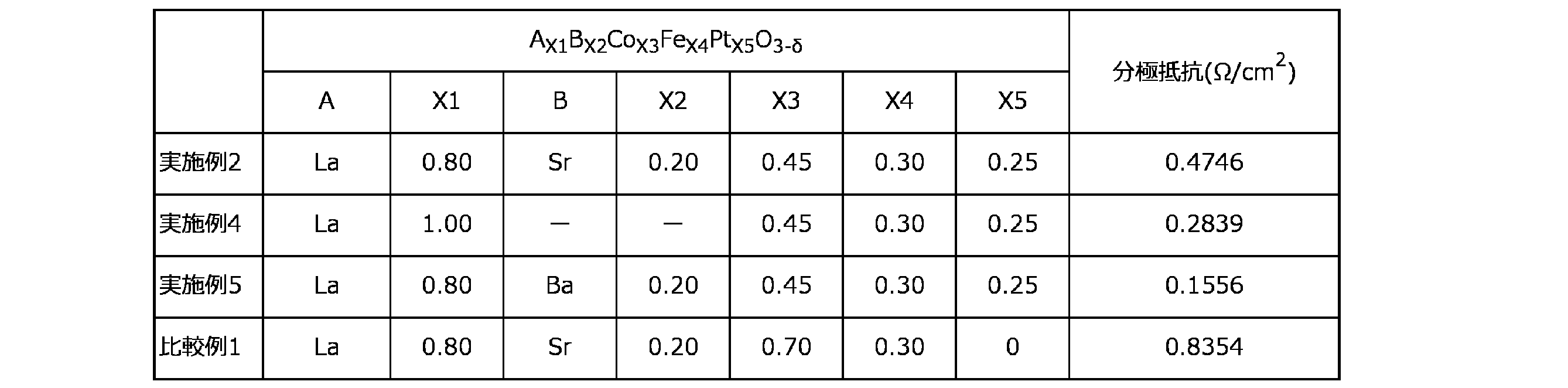
表1に示す結果から明らかなとおり、各実施例で得られた酸化物から製造された固体電解質接合体は、600℃という比較的低温において比較例の固体電解質接合体に比べて電流密度が高いことが分かる。
表2に示す結果から明らかなとおり、各実施例で得られた酸化物は、比較例の酸化物よりも分極抵抗が低いことが分かる。
表2に示す結果から明らかなとおり、各実施例で得られた酸化物は、比較例の酸化物よりも分極抵抗が低いことが分かる。
本発明の酸化物によれば、該酸化物を有するガスセンサ等のデバイスの作動温度の低下及び応答速度の向上が可能となり、また該酸化物を有する燃料電池の出力特性を向上させることが可能となる。
Claims (8)
- 式:AaBbCcDdO3-δ
(式中、Aは第3族元素を表し、
Bは第2族元素を表し、
Cは第8族元素及び第9族元素から選択される元素を表し、
Dは白金族元素及び金から選択される元素を表し、
aは、0.10以上1.10以下の数を表し、
bは、0以上0.90以下の数を表し、
cは、0.40以上1.10以下の数を表し、
dは、0.15以上0.40以下の数を表し、
a+bは、0.80以上1.20以下であり、
c+dは、0.80以上1.20以下であり、
δは、A、B、C、D及びOの価数及び量に起因して生じる端数である。)
で表され、ペロブスカイト型結晶構造を有する酸化物。 - 第3族元素がLaであり、
第2族元素がSr又はBaであり、
第8族元素がCoであり、
第9族元素がFeである、
請求項1に記載の酸化物。 - 請求項1又は2に記載の酸化物からなる層と、固体電解質の層とが接合されてなる固体電解質接合体。
- 前記固体電解質が酸化物イオン伝導体である、請求項3に記載の固体電解質接合体。
- 前記固体電解質がアパタイト型複合酸化物である、請求項3に記載の固体電解質接合体。
- 前記固体電解質が、一般式:E9.33+x[T6.00-yMy]O26.0+z(式中のEは、La、Ce、Pr、Nd、Sm、Eu、Gd、Tb、Dy、Be、Mg、Ca、Sr及びBaからなる群から選ばれた一種又は二種以上の元素である。式中のTは、Si若しくはGe又はその両方を含む元素である。式中のMは、B、Ge、Zn、Sn、W及びMoからなる群から選ばれた一種又は二種以上の元素である。)で表され、式中のxは-1.00以上1.00以下の数であり、式中のyは0.40以上3.00以下の数であり、式中のzは-3.00以上2.00以下の数であり、Mのモル数に対するAのモル数の比率が3.00以上26.0以下である複合酸化物を含む、請求項3に記載の固体電解質接合体。
- 前記固体電解質に0.5Vの直流電圧を印加して得られる電流密度が、大気中、600℃において170mA/cm2以上である、請求項3に記載の固体電解質接合体。
- 前記固体電解質の層における、前記酸化物の層が配置された面と反対側の面に、前記酸化物と異なる酸化物の層又は金属の層が接合されている、請求項3に記載の固体電解質接合体。
Priority Applications (1)
| Application Number | Priority Date | Filing Date | Title |
|---|---|---|---|
| JP2025530206A JPWO2025005204A1 (ja) | 2023-06-30 | 2024-06-27 |
Applications Claiming Priority (2)
| Application Number | Priority Date | Filing Date | Title |
|---|---|---|---|
| JP2023108872 | 2023-06-30 | ||
| JP2023-108872 | 2023-06-30 |
Publications (1)
| Publication Number | Publication Date |
|---|---|
| WO2025005204A1 true WO2025005204A1 (ja) | 2025-01-02 |
Family
ID=93939236
Family Applications (1)
| Application Number | Title | Priority Date | Filing Date |
|---|---|---|---|
| PCT/JP2024/023436 Ceased WO2025005204A1 (ja) | 2023-06-30 | 2024-06-27 | 酸化物及びこれを有する固体電解質接合体 |
Country Status (2)
| Country | Link |
|---|---|
| JP (1) | JPWO2025005204A1 (ja) |
| WO (1) | WO2025005204A1 (ja) |
Citations (5)
| Publication number | Priority date | Publication date | Assignee | Title |
|---|---|---|---|---|
| JP2001224963A (ja) * | 2000-02-16 | 2001-08-21 | Nissan Motor Co Ltd | 触媒組成物、その製造方法及びその使用方法 |
| JP2007084390A (ja) * | 2005-09-26 | 2007-04-05 | Toyota Motor Corp | ペロブスカイト型複合酸化物粒子とその製造方法 |
| WO2016111110A1 (ja) * | 2015-01-07 | 2016-07-14 | 三井金属鉱業株式会社 | 配向性アパタイト型酸化物イオン伝導体及びその製造方法 |
| CN111430734A (zh) * | 2020-03-19 | 2020-07-17 | 华南理工大学 | (Pr0.5Sr0.5)xFe1-yRuyO3-δ钙钛矿材料及其制备方法与应用 |
| KR20230033475A (ko) * | 2021-09-01 | 2023-03-08 | 한국과학기술원 | 고체산화물 연료전지용 lscfp계 전극 소재 및 제조방법 |
-
2024
- 2024-06-27 JP JP2025530206A patent/JPWO2025005204A1/ja active Pending
- 2024-06-27 WO PCT/JP2024/023436 patent/WO2025005204A1/ja not_active Ceased
Patent Citations (5)
| Publication number | Priority date | Publication date | Assignee | Title |
|---|---|---|---|---|
| JP2001224963A (ja) * | 2000-02-16 | 2001-08-21 | Nissan Motor Co Ltd | 触媒組成物、その製造方法及びその使用方法 |
| JP2007084390A (ja) * | 2005-09-26 | 2007-04-05 | Toyota Motor Corp | ペロブスカイト型複合酸化物粒子とその製造方法 |
| WO2016111110A1 (ja) * | 2015-01-07 | 2016-07-14 | 三井金属鉱業株式会社 | 配向性アパタイト型酸化物イオン伝導体及びその製造方法 |
| CN111430734A (zh) * | 2020-03-19 | 2020-07-17 | 华南理工大学 | (Pr0.5Sr0.5)xFe1-yRuyO3-δ钙钛矿材料及其制备方法与应用 |
| KR20230033475A (ko) * | 2021-09-01 | 2023-03-08 | 한국과학기술원 | 고체산화물 연료전지용 lscfp계 전극 소재 및 제조방법 |
Non-Patent Citations (3)
| Title |
|---|
| MARASI MARTINA, PANUNZI ANNA PAOLA, DURANTI LEONARDO, LISI NICOLA, DI BARTOLOMEO ELISABETTA: "Enhancing Oxygen Reduction Activity and Structural Stability of La 0.6 Sr 0.4 FeO 3−δ by 1 mol % Pt and Ru B-Site Doping for Application in All-Perovskite IT-SOFCs", ACS APPLIED ENERGY MATERIALS, AMERICAN CHEMICAL SOCIETY, vol. 5, no. 3, 28 March 2022 (2022-03-28), pages 2918 - 2928, XP093254825, ISSN: 2574-0962, DOI: 10.1021/acsaem.1c03613 * |
| PANUNZI ANNA PAOLA, DURANTI LEONARDO, LUISETTO IGOR, LISI NICOLA, MARELLI MARCELLO, DI BARTOLOMEO ELISABETTA: "Triggering electrode multi-catalytic activity for reversible symmetric solid oxide cells by Pt-doping lanthanum strontium ferrite", CHEMICAL ENGENEERING JOURNAL, ELSEVIER, AMSTERDAM, NL, vol. 471, 1 September 2023 (2023-09-01), AMSTERDAM, NL , pages 144448, XP093254824, ISSN: 1385-8947, DOI: 10.1016/j.cej.2023.144448 * |
| ZHOU FENG, ZHOU LIHONG, HU MINGYAO, TONG XIN, LIU YIHUI, LI HAIZHAO, YANG SHENGBING, WEI MINGRUI: "Pd-doped La0.6Sr0.4Co0.2Fe0.8O3−δ perovskite oxides as cathodes for intermediate temperature solid oxide fuel cells", SOLID STATE IONICS, NORTH HOLLAND PUB. COMPANY. AMSTERDAM; NL, NL, vol. 319, 4 February 2018 (2018-02-04), NL , pages 22 - 27, XP055917446, ISSN: 0167-2738, DOI: 10.1016/j.ssi.2018.01.044 * |
Also Published As
| Publication number | Publication date |
|---|---|
| JPWO2025005204A1 (ja) | 2025-01-02 |
Similar Documents
| Publication | Publication Date | Title |
|---|---|---|
| Tan et al. | Performance enhancement of solution impregnated nanostructured La0. 8Sr0. 2Co0. 8Ni0. 2O3-δ oxygen electrode for intermediate temperature solid oxide electrolysis cells | |
| CN111919113B (zh) | 具有中间层的固体电解质接合体 | |
| Hu et al. | Iron stabilized 1/3 A-site deficient La–Ti–O perovskite cathodes for efficient CO 2 electroreduction | |
| JP7291031B2 (ja) | 固体電解質接合体 | |
| Garcia et al. | Citrate–hydrothermal synthesis, structure and electrochemical performance of La0. 6Sr0. 4Co0. 2Fe0. 8O3− δ cathodes for IT-SOFCs | |
| Chaianansutcharit et al. | Ruddlesden Popper oxides of LnSr 3 Fe 3 O 10− δ (Ln= La, Pr, Nd, Sm, Eu, and Gd) as active cathodes for low temperature solid oxide fuel cells | |
| Qi et al. | Single-phase nickel-doped ceria cathode with in situ grown nickel nanocatalyst for direct high-temperature carbon dioxide electrolysis | |
| Filonova et al. | Assessment of prospective cathodes based on (1-x) Ca3Co4O9+ δ-x BaCe0. 5Zr0. 3Y0. 1Yb0. 1O3-δ composites for protonic ceramic electrochemical cells | |
| US20150244001A1 (en) | Method and an electrode produced by infiltration | |
| US20040214070A1 (en) | Low sintering lanthanum ferrite materials for use as solid oxide fuel cell cathodes and oxygen reduction electrodes and other electrochemical devices | |
| JP4931362B2 (ja) | 燃料電池セル及び燃料電池 | |
| Melo et al. | Understanding the oxygen reduction reaction of one-dimensional Ca3Co2O6 cathodes for SOFC | |
| JP7265538B2 (ja) | 固体電解質接合体 | |
| Wongsawatgul et al. | Ca and Pr substitution promoted the cell performance in LnSr3Fe3O10-δ cathode for solid oxide fuel cells | |
| JP6315581B2 (ja) | 固体酸化物形燃料電池用カソード及びその製造方法、並びに当該カソードを備える固体酸化物形燃料電池 | |
| JP7123078B2 (ja) | 酸素透過素子及びスパッタリングターゲット材 | |
| Bu et al. | Composites of single/double perovskites as cathodes for solid oxide fuel cells | |
| WO2025005204A1 (ja) | 酸化物及びこれを有する固体電解質接合体 | |
| CN1781204A (zh) | 固体氧化物燃料电池用燃料电极和使用其的固体氧化物燃料电池 | |
| WO2020004333A1 (ja) | 固体酸化物形セル用電極及びそれを用いた固体酸化物形セル | |
| Shamshi Hassan et al. | Electrocatalytic behavior of calcium doped LaFeO3 as cathode material for solid oxide fuel cell | |
| JP7291057B2 (ja) | 排気ガス用酸素センサ素子 | |
| CN1921196A (zh) | 一种复相电催化材料及其制备方法 | |
| JP3598956B2 (ja) | ガレート複合酸化物固体電解質材料とその製造方法 | |
| JP2022130974A (ja) | 固体電解質接合体及びその製造方法 |
Legal Events
| Date | Code | Title | Description |
|---|---|---|---|
| 121 | Ep: the epo has been informed by wipo that ep was designated in this application |
Ref document number: 24832062 Country of ref document: EP Kind code of ref document: A1 |
|
| ENP | Entry into the national phase |
Ref document number: 2025530206 Country of ref document: JP Kind code of ref document: A |
|
| WWE | Wipo information: entry into national phase |
Ref document number: 2025530206 Country of ref document: JP |
|
| NENP | Non-entry into the national phase |
Ref country code: DE |