WO2025004414A1 - コネクタ - Google Patents
コネクタ Download PDFInfo
- Publication number
- WO2025004414A1 WO2025004414A1 PCT/JP2023/047036 JP2023047036W WO2025004414A1 WO 2025004414 A1 WO2025004414 A1 WO 2025004414A1 JP 2023047036 W JP2023047036 W JP 2023047036W WO 2025004414 A1 WO2025004414 A1 WO 2025004414A1
- Authority
- WO
- WIPO (PCT)
- Prior art keywords
- connector
- locking
- mating
- housing
- load
- Prior art date
- Legal status (The legal status is an assumption and is not a legal conclusion. Google has not performed a legal analysis and makes no representation as to the accuracy of the status listed.)
- Ceased
Links
Images









Classifications
-
- H—ELECTRICITY
- H01—ELECTRIC ELEMENTS
- H01R—ELECTRICALLY-CONDUCTIVE CONNECTIONS; STRUCTURAL ASSOCIATIONS OF A PLURALITY OF MUTUALLY-INSULATED ELECTRICAL CONNECTING ELEMENTS; COUPLING DEVICES; CURRENT COLLECTORS
- H01R12/00—Structural associations of a plurality of mutually-insulated electrical connecting elements, specially adapted for printed circuits, e.g. printed circuit boards [PCB], flat or ribbon cables, or like generally planar structures, e.g. terminal strips, terminal blocks; Coupling devices specially adapted for printed circuits, flat or ribbon cables, or like generally planar structures; Terminals specially adapted for contact with, or insertion into, printed circuits, flat or ribbon cables, or like generally planar structures
- H01R12/70—Coupling devices
- H01R12/71—Coupling devices for rigid printing circuits or like structures
-
- H—ELECTRICITY
- H01—ELECTRIC ELEMENTS
- H01R—ELECTRICALLY-CONDUCTIVE CONNECTIONS; STRUCTURAL ASSOCIATIONS OF A PLURALITY OF MUTUALLY-INSULATED ELECTRICAL CONNECTING ELEMENTS; COUPLING DEVICES; CURRENT COLLECTORS
- H01R13/00—Details of coupling devices of the kinds covered by groups H01R12/70 or H01R24/00 - H01R33/00
- H01R13/62—Means for facilitating engagement or disengagement of coupling parts or for holding them in engagement
- H01R13/639—Additional means for holding or locking coupling parts together, after engagement, e.g. separate keylock, retainer strap
Definitions
- the present invention relates to a connector.
- connectors in which a mating connector is mated or removed by moving the mating connector along a third direction (e.g., up-down direction) that is perpendicular to an imaginary plane formed by a first direction (e.g., left-right direction) and a second direction (e.g., front-rear direction) that are perpendicular to each other.
- a third direction e.g., up-down direction
- first direction e.g., left-right direction
- second direction e.g., front-rear direction
- Patent Document 1 discloses a connector equipped with a locking mechanism as shown in FIG. 31. That is, in the connector (100) disclosed in Patent Document 1, two restriction mechanisms (500) are provided for each of the two additional members (400) provided in the connector (100), totaling four restriction mechanisms (500).
- Each of the four restriction mechanisms (500) is a U-shaped plate-like spring member, and a protrusion (511) as a locking part is formed on the root side of the elastically deformable spring member, and an operating part (550) is formed on the tip side of the spring member. When an operator operates the operating part (550) formed on the tip side of the spring, the protrusion (511) formed on the root side of the spring can be moved.
- the protrusion (511) engages with the mating connector to maintain the mated state of the connectors, and the protrusion (511) separates from the mating connector to release the mated state of the connectors.
- symbols used in the explanations of prior art documents are placed in parentheses to distinguish them from the embodiments of the present invention.
- the regulating mechanism (500) as a spring member provided in the connector disclosed in Patent Document 1 is generally a member formed by punching a metal plate and performing press processing or the like. In press processing, it is difficult to precisely control the opening dimension at the tip end of the regulating mechanism (500) as a U-shaped plate-like spring member, and there is an issue that the opening dimension of this spring member inevitably varies during manufacturing.
- This U-shaped plate-like spring member is provided with an operating portion (550) that is operated by an operator and a protrusion (511) as a locking portion, and the variation in the opening dimension of the spring member means the variation in the positions of these in the connector. In particular, there is a large variation in the position of the operating portion (550) provided at the tip end of the spring member in the connector of Patent Document 1.
- the present invention aims to provide a connector equipped with a mechanism having a U-shaped plate-like spring member and an operating part and a locking part connected thereto, which eliminates variation in the opening dimensions of the U-shaped plate-like spring member and eliminates variation in the positions of the operating part and the locking part.
- the connector of the present invention is a connector in which a mating connector is mated or removed by moving the mating connector along a third direction perpendicular to an imaginary plane formed by a first direction and a second direction perpendicular to each other, the connector comprising a housing, a plurality of terminals, and two additional members, the housing comprising a terminal holding portion and two island portions, the plurality of terminals being held by the terminal holding portion and arranged in the first direction on the housing, the two additional members being held by the housing and positioned at both ends of the housing in the first direction, and each of the two additional members being arranged so as to face each other in the second direction.
- the connector further includes two locking mechanisms positioned at the first and second positions, each of the two locking mechanisms including a spring portion, an extension portion, a locking portion, an operation portion, and a pressure-receiving portion, the spring portion being a plate-like elastic member having a U-shape that is closed on one side of the outside or inside of the connector in the first direction and open on the other side of the outside or inside when viewed in the third direction, the outer end of the U-shape of the connector in the second direction being formed as a fixed end, and the inner end of the U-shape of the connector in the second direction being formed as a free end, and the extension portion is continuous with the inner end of the connector in the second direction that is formed as the free end of the U-shaped spring portion and extends in the first direction.
- the locking portion is formed on the inside of the connector in the second direction of the extension portion and has a locking surface facing one of the third directions;
- the operation portion is formed on the inside of the connector in the second direction of the extension portion at a position outside the locking portion of the connector in the first direction of the extension portion, and is capable of moving between a non-release position and a release position outside the connector in the second direction relative to the non-release position, the release position being located when the operation portion is subjected to a pressing operation toward the outside of the connector in the second direction;
- the pressed load portion is formed on the inside of the connector in the first direction of the extension portion and is capable of moving between a non-release position and a release position outside the connector in the second direction relative to the non-release position,
- the extension is provided at a position between the locking portion and the operating portion, on the inside of the connector in the second direction, and each of the two island portions has two pressure load portions facing the outside of the connector in the second direction, and each of the pressure-receiving portions faces
- a pressure load portion is provided on the housing, and a pressure-receiving portion is provided on an extension portion on which the locking portion and operating portion are provided, continuous with a spring portion which is a U-shaped, plate-like elastic member, and when the lock release operation is not being performed (i.e., when the operating portion is in the non-release position), the pressure application portion constantly contacts and presses the pressure-receiving portion to apply a preload.
- the opening of the spring when the operating portion is in the non-release position is determined by the pressure application portion and not by the natural state of the member, and the positions of the locking portion and operating portion are always defined in predetermined positions by the pressure load portion provided on the housing.
- the present invention makes it possible to eliminate the manufacturing variation in the opening dimensions of the U-shaped plate spring member (the spring portion and extension portion, which are elastic members) that is a component of the locking mechanism that maintains and releases the mated state of the connectors, and to provide a connector in which the positions of the locking portion and operating portion connected to the spring member are defined and consistent.
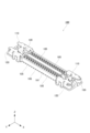
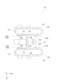
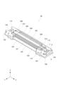
- FIG. 1 is a top perspective view showing a connector according to the present embodiment and a mating connector.
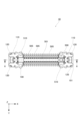
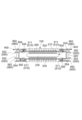
- FIG. 2 is a top view showing the connector of FIG. 1 and a mating connector.
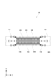
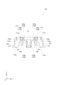
- FIG. 3 is a bottom view showing the connector of FIG. 1 and a mating connector.
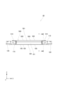
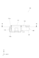
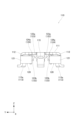
- FIG. 4 is a front view showing the connector of FIG. 1 and a mating connector.
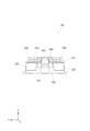
- FIG. 5 is a right side view showing the connector of FIG. 1 and the mating connector.
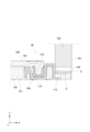
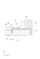
- FIG. 6 is a cross-sectional view showing the connector and the mating connector of FIG. 2 taken along line 6-6.
- FIG. 7 is a cross-sectional view showing the connector and the mating connector of FIG. 4 taken along line 7-7.
- FIG. 8 is an upper perspective view showing a state in which the mating connector has been removed from the connector of this embodiment.
- FIG. 9 is a bottom perspective view showing the mating connector of the present embodiment.
- FIG. 10 is a bottom perspective view showing the mating connector of the present embodiment in an exploded state.
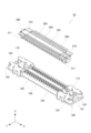
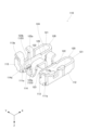
- FIG. 11 is a top perspective view showing the connector of the present embodiment.
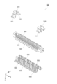
- FIG. 12 is an upper perspective view showing the connector of this embodiment in an exploded state.
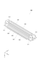
- FIG. 13 is a top perspective view showing an additional member that constitutes the connector of this embodiment.
- FIG. 14 is a bottom perspective view showing an additional member that constitutes the connector of this embodiment.
- FIG. 15 is a top view showing an additional member constituting the connector of this embodiment.
- FIG. 16 is a bottom view showing an additional member constituting the connector of this embodiment.
- FIG. 17 is a front view showing an additional member that constitutes the connector of this embodiment.
- FIG. 18 is a cross-sectional view showing the additional member of FIG. 17 taken along line 18-18.
- FIG. 19 is a right side view showing an additional member that constitutes the connector of this embodiment.
- FIG. 20 is a left side view showing an additional member that constitutes the connector of this embodiment.
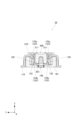
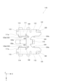
- FIG. 21 is a front view showing the connector of the present embodiment. 22 is a cross-sectional view of the connector of FIG. 21 taken along line 22-22.
- Fig. 23 is a cross-sectional view showing a modification of the connector of the present embodiment shown in Fig. 22. Note that Fig. 23 shows a locking mechanism of an additional member provided on the left side of the connector.
- FIG. 23 shows a locking mechanism of an additional member provided on the left side of the connector.
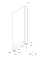
- FIG. 24 is a bottom perspective view showing the unlocking tool of this embodiment.
- 25 is a front view for explaining a method of using the unlocking tool of this embodiment, showing a state before the connector assembly is unlocked.
- the first circuit board and the second circuit board are indicated by dashed lines.
- 26 is a front view for explaining a method of using the unlocking tool of this embodiment, showing the state when the connector assembly is unlocked.
- the first circuit board and the second circuit board are indicated by dashed lines.
- FIG. 27 is a right side view illustrating a method of using the unlocking tool of this embodiment, showing the state when the connector assembly is unlocked.
- 28 is a cross-sectional view showing the connector, the mating connector, and the unlocking jig of FIG.
- FIG. 27 taken along line 28-28.
- 29 is a cross-sectional view showing the connector, the mating connector, and the unlocking jig of FIG. 27 taken along line 29-29.
- FIG. 30 is a diagram for explaining the relationship between the unlocking tool, the connector, and the mating connector of this embodiment, showing a perspective view of the connector and the mating connector as viewed from above.
- FIG. 31 is a cross-sectional view showing an example of a schematic configuration of the connector of Patent Document 1.
- the first direction is the left-right direction.
- the left-right direction is shown as the X direction.
- the right side is the +X direction
- the left side is the -X direction.
- the second direction is the front-back direction.
- the front-back direction is shown as the Y direction.
- the front side is the +Y direction
- the rear side is the -Y direction.
- the third direction is the up-down direction.
- the up-down direction is shown as the Z direction.
- the top is the +Z direction
- the bottom is the -Z direction.
- the connector 100 of this embodiment constitutes a connector assembly 10 together with a mating connector 500.
- the mating connector 500 is configured as a plug connector
- the connector 100 is configured as a receptacle connector.
- the mating connector 500 is moved along a third direction (Z: up-down direction) that is perpendicular to an imaginary plane formed by a first direction (X: left-right direction) and a second direction (Y: front-rear direction) that are perpendicular to each other, so that the mating connector 500 is mated with or removed from the connector 100.
- Z up-down direction
- X left-right direction
- Y front-rear direction
- the mating connector 500 of this embodiment includes a mating housing 501, a plurality of mating terminals 505, and two mating additional members 510.
- the multiple mating terminals 505 are made of a conductive metal material and are formed, for example, by punching a metal plate and performing press processing or the like. In this embodiment, the multiple mating terminals 505 are held by the mating terminal holding portion 503 of the mating housing 501 and are arranged in a direction along the left-right direction, which is the first direction.
- the mating housing 501 and the multiple mating terminals 505 can be integrally formed, for example, by injection molding or the like.
- the two mating additional members 510 are members that are held by the mating housing 501 and are located at both ends of the mating housing 501 in the left-right direction, which is the first direction.
- the two mating additional members 510 are attached to the housing 501 by fitting them from below upward (in the +Z direction) into both ends of the housing 501, which has a plurality of mating terminals 505 integrally formed by injection molding or the like.
- the mating additional members 510 are formed, for example, from a metal material.
- each of the two mating additional members 510 in this embodiment has a locking hole 511 on the front and rear surfaces.
- the mating connector 500 in this embodiment has a total of four locking hole portions 511, one on the front and rear surfaces of each of the left and right ends. These four locking hole portions 511 are locked by engagement with the locking portion 123 of the locking mechanism 120 of the connector 100 described below, so that the mating state of the mating connector 500 relative to the connector 100 can be maintained.
- the connector 100 of this embodiment includes a housing 101, multiple terminals 105, and two additional members 110.
- the housing 101 is a member that functions as an insulator, and is formed, for example, from a resin material.
- the housing 101 also includes a terminal holding portion 103 and two island portions 107.
- a plurality of terminals 105 are installed on the terminal holding portion 103.
- the two island portions 107 are formed at positions that respectively correspond to two additional members 110, which will be described later.
- the multiple terminals 105 are made of a conductive metal material and are formed, for example, by punching a metal plate and performing press processing or the like. In this embodiment, the multiple terminals 105 are held in the terminal holding portion 103 of the housing 101 and are arranged in a direction along the first direction, that is, the left-right direction.
- the housing 101 and the multiple terminals 105 can be integrally formed, for example, by injection molding or the like. In this case, the terminal holding portion 103 is formed simultaneously with the injection molding, so that it is inseparable from the multiple terminals 105.
- the housing 101 in this embodiment may also be formed by previously forming the housing 101, which is made of a resin material, and fitting the multiple terminals 105 into the previously formed terminal holding portion 103.
- the two additional members 110 are members that are held by the housing 101 and are located at both ends of the housing 101 in the left-right direction, which is the first direction.
- the two additional members 110 are attached to the housing 101 by fitting them from above downward (in the -Z direction) into both ends of the housing 101, which has a plurality of terminals 105 integrally formed by injection molding or the like.
- the two additional members 110 and the above-mentioned two island portions 107 overlap in the left-right direction (X direction), and more specifically, regarding this embodiment, the positional range of the island portion 107 in the left-right direction (X direction) is included within the positional range of the corresponding additional member 110.
- each additional member 110 has a concave shape that can be placed from above downward (in the -Z direction) over the corresponding island portion 107 that protrudes upward (in the +Z direction). That is, the two additional members 110 are attached to the housing 101 by fitting them into the portions including the corresponding island portions 107 on both ends of the housing 101.
- the additional members 110 are formed of, for example, a metal material.
- each of the two additional members 110 in this embodiment is equipped with a locking mechanism 120 that realizes a locked state by engaging with four locking hole portions 511 of the mating connector 500.
- Two locking mechanisms 120 are provided for each of the two additional members 110.
- the connector 100 is equipped with a total of four locking mechanisms 120, two on each of the left and right ends.
- Figures 13 to 20 show the additional member 110 installed on the right side of the connector 100.
- the additional member 110 of this embodiment has two locking mechanisms 120 positioned to face each other in the second direction, that is, the front-rear direction.
- Each of the two locking mechanisms 120 has a spring portion 121, an extension portion 122, a locking portion 123, an operating portion 124, and a pressure-bearing portion 125.
- the spring portion 121 is a portion formed as a plate-like elastic member having a U-shape that is closed on the outside of the connector 100 in the first direction, the left-right direction, and open on the inside when viewed in the third direction, the up-down direction.
- the outer end of the spring portion 121 in the second direction, the front-rear direction, of the U-shape is connected to and fixed to a portion of the additional member 110 other than the locking mechanism 120 (in this example, the bent portion 112 described below) and forms a fixed end, and the inner end of the connector 100 in the second direction, the front-rear direction, of the U-shape is formed as a free end.
- the extension 122 is a member that is continuous with the inner end of the connector 100 in the front-to-rear direction, which is the second direction, and is formed as a free end of the U-shaped spring portion 121.
- the extension 122 is formed to extend in the left-to-right direction, which is the first direction, so that it can be displaced in the front-to-rear direction, which is the second direction, by the elastic force of the spring portion 121.
- the locking portion 123 is formed on the inside of the connector 100 in the front-to-rear direction, which is the second direction of the extension portion 122. As shown in the cross-sectional shape in Figure 7, the locking portion 123 has a slope 123a formed on the upper side and a locking surface 123b formed on the lower side, which is a flat surface facing downward, which is one of the up-down directions, which is the third direction.
- the lower locking surface 123b of the locking portion 123 faces the inner surface of the locking hole 155 of the mating additional member 510, and even if the mating connector 500 is moved in a direction (+Z direction) to remove it from the connector 100 while the mating connector 500 and the connector 100 are engaged, the upward movement of the mating connector 500 in the third direction, the vertical direction, is restricted by the locking surface 123b hitting the inner surface of the locking hole 511.
- the locking surface 123b facing downward which is one of the vertical directions that is the third direction of the locking portion 123, restricts the movement of the mating connector 500 in the third direction, the vertical direction, and prevents it from being removed from the connector 100.
- the operating part 124 is located between the spring part 121 and the locking part 123 in the left-right direction, which is the first direction of the extension part 122, and is formed inside the connector 100 in the front-rear direction, which is the second direction of the extension part 122.
- the operating part 124 is also formed so as to be able to move between a non-release position, which is located when no pressing operation is received, and a release position, which is located outside the connector 100 in the front-rear direction, which is the second direction, and is located when a pressing operation toward the outside of the connector 100 in the front-rear direction, which is the second direction, is received.
- a non-release position and release position of the operating part 124 as shown in FIG.
- the non-release position is a state in which the locking part 123 is fitted into the locking hole part 511 of the counterpart additional member 510
- the release position is a state in which the locking part 123 moves from the locking hole part 511 of the counterpart additional member 510 to the left-right outside of the connector 100 and comes out of the locking hole part 511 to release the engagement state.
- the operating unit 124 is formed with a sliding slope 124a on the upper side.
- the operating unit 124 is pressed by the unlocking tool 700 described later so as to spread outward in the second direction, i.e., the front-rear direction.
- This pressing operation is an operation in which the pressing legs 701 of the unlocking tool 700 are pressed downward from an upper position in the -Z direction against the sliding slope 124a of the operating unit 124. In this pressing operation, the pressing legs 701 apply a pressing force while sliding on the surface of the sliding slope 124a of the operating unit 124.
- the operating unit 124 Since the operating unit 124 has the sliding slope 124a, an operating error in which the pressing legs 701 erroneously press the operating unit 124 down is extremely unlikely to occur, and the pressing legs 701 can smoothly move the operating unit 124 from the non-released position to the released position.
- the operating unit 124 is disposed on the side closer to the U-shaped spring portion 121 of the locking mechanism 120 which functions as an elastic member, i.e., on the root side of the elastic deformation of the locking mechanism 120 where the extension portion 122 is displaced, and the locking unit 123 is disposed at the tip, so that when the operating unit 124 is pressed to move from the non-released position to the released position, the locking unit 123, which moves in conjunction with the operating unit 124, moves by a larger amount than the operating unit 124.
- the locking mechanism 120 of this embodiment can set the amount of displacement of the operating unit 124 smaller than in the prior art, while ensuring the necessary amount of displacement of the locking unit 123.
- the amount by which the non-released position of the operating unit 124 protrudes inward in the second direction (front-to-back direction) from the top plate 111 described below in FIG. 15 in this embodiment that is, the amount by which the operating unit 124 is exposed from the top plate 111 to wait for a pressing operation, can be set smaller than in the prior art.
- the additional member 110 of this embodiment shown in Figures 13 to 20 further includes a top plate 111 and a folding portion 112.
- the top plate 111 is formed in a position that at least partially covers the spring portion 121 and the extension portion 122 when viewed downward in the third direction, which is the up-down direction, and is a member formed with an extension parallel to an imaginary plane formed by the first direction, which is the left-right direction, and the second direction, which is the front-rear direction.
- the bent portion 112 is a curved bent portion that connects the outer end of the connector 100 in the front-to-rear direction, which is the second direction of the U-shape that constitutes the spring portion 121, to the top plate 111.
- the locking mechanism 120 described above is formed by connecting the outer end of the U-shaped spring portion 121 in the front-to-rear direction to the lower end of the bent portion 112.
- the additional member 110 of this embodiment is provided with a hold-down 113.
- the hold-down 113 is formed continuous with the end 111a formed on the inside of the connector 100 in the left-right direction, which is the first direction of the top plate 111, and is a portion formed by extending from the end 111a downward in the -Z direction.
- a soldering portion 113a is provided at the end opposite the connection portion with the end 111a, i.e., the lower end, and, for example, as shown in Figures 25 and 26, when the underside of the connector 100 is placed on the second circuit board 151, the soldering portion 113a can be soldered to the second circuit board 151.
- the attachment of the additional member 110 which is equipped with a locking mechanism 120 to which an upward external force is applied when attempting to remove the mating connector 500, to the second circuit board 151 becomes more secure.
- the additional member 110 of this embodiment is provided with a regulating portion 114.
- the regulating portion 114 is formed as a portion extending from the top plate 111 toward the vicinity of the extension portion 122, and is provided with a regulating surface 114a that faces downward in the up-down direction (third direction).
- the regulating surface 114a is fixed to the top plate 111 and faces downward.
- the surface of the portion of the extension portion 122 that faces the regulating surface 114a is formed as the regulated surface 122a.
- the restricting surface 114a and the restricted surface 122a face each other with a gap therebetween, and when an upward external force is applied to the extension portion 122 on which the locking portion 123 is formed, for example, by forcibly removing the mating connector 500 while the locking portion 123 is still fitted into the locking hole portion 511 of the mating connector 500, the restricted surface 122a abuts against the restricting surface 114a.
- the restricted surface 122a abuts against the restricting surface 114a in this way, the irregular upward movement of the extension portion 122 is strongly restricted by the restricting portion 114.
- the restricting portion 114 is formed so that the locking mechanism 120 acts more reliably.
- the locking portion 123 and the regulated surface 122a formed on the extension portion 122 are preferably arranged so that their positions in the X direction (left-right direction) of the extension portion 122, i.e., the first direction, at least partially overlap (see FIG. 13, etc.).
- the locking portion 123 to which an upward force is applied and the regulated surface 122a to which a downward force is applied by hitting the regulating surface 114a are arranged in overlapping positions in the extension direction of the extension portion 122, i.e., the X direction (first direction), thereby preventing the generation of torque or bending stress in the extension portion 122, making the action of the regulating portion 114 more effective, and preferably preventing the occurrence of defects such as damage to the locking mechanism 120.
- the pressure-receiving portion 125 of the locking mechanism 120 of this embodiment is formed inside the connector 100 in the front-rear direction, which is the second direction of the extension portion 122, at a position between the locking portion 123 and the operating portion 124 in the left-right direction, which is the first direction of the extension portion 122.
- the connector 100 of this embodiment is provided with a total of four locking mechanisms 120, two on each of the two additional members 110.
- each of the two island portions 107 of the housing 101 is provided with a total of two pressure-receiving portions 107a facing away from each other toward the outside of the connector 100 in the front-rear direction, which is the second direction. That is, as is clear from a comparison between FIG. 12 and FIG. 22, in the connector 100 of this embodiment, each of the four pressure-receiving load parts 125 provided in the locking mechanism 120 is arranged opposite one of the corresponding pressure-receiving load parts 107a in the front-rear direction, which is the second direction.
- each of the pressure-receiving portions 125 is in contact with the corresponding pressure-receiving portion 107a and is configured to receive a pressure load toward the outside of the connector 100 in the second direction, the front-rear direction (see the state in Figure 22).
- the opening dimension of the tip of the U-shaped spring member including the spring portion 121 and the extension portion 122 in the natural state varies due to the lack of control by the press processing used to manufacture the additional member 110.
- the position of the tip of the extension portion 122 acting as a free end on the side farther from the spring portion 121 in the front-rear direction, which is the second direction varies in the natural state in which the extension portion 122 is not subjected to an external force.
- the spring member is not in the natural state, and the pressure-receiving load portion 125 of the extension portion 122 is in contact with the pressure load portion 107a and receives a pressure load as an external force.
- the position of the extension portion 122 in the front-rear direction, which is the second direction is determined by the pressure load portion 107a provided on the housing 101.
- the extension portion 122 elastically supported by the spring portion 121 is constantly pressed and preloaded when the unlocking operation is not performed (i.e., when the operation portion 124 is in the non-release position). Therefore, since the positions of the locking portion 123 and the operation portion 124 when the unlocking operation is not performed (i.e., when the operation portion 124 is in the non-release position) are always defined to predetermined positions by the pressure load portion 107a provided on the housing 101, it is possible to eliminate the effects of dimensional variations in the opening of the spring member (a U-shaped elastic member including the spring portion 121 and the extension portion 122) that inevitably occur during the manufacture of the additional member 110.
- each of the two pressed load portions 125 that were in contact with the two pressing load portions 107a of the island portion 107 moves toward the outside of the connector 100 in the front-rear direction, which is the second direction, and moves away from the corresponding pressing load portion 107a.
- the U-shaped plate-like spring member which is a component of the locking mechanism 120 responsible for maintaining and releasing the mated state of the connector 100 and the mating connector 500, and in particular, it is possible to realize a connector 100 in which the position of the locking portion 123 in the locked state is determined without variation, thereby providing a connector 100 that can stably achieve a locked state in the mated state of the connector 100 and the mating connector 500.
- the mating connector 500 When mating the mating connector 500 with the connector 100, as shown in FIG. 8, the mating connector 500 is moved downward in the -Z direction to fit the mating connector 500 into the connector 100. At this time, the surface of the mating additional member 510 of the mating connector 500 slides along the inclined surface 123a of the locking portion 123 as it is pushed into the connector 100, so that the extension 122 is displaced once toward the outside in the front-rear direction, which is the second direction of the connector 100, and then the extension 122 is displaced back toward the inside in the front-rear direction, which is the second direction of the connector 100, so that the locking portion 123 fits into the locking hole 511 of the additional member 510.
- This action realizes the engagement between the locking hole 511 and the locking portion 123 shown in FIG. 7, and achieves a locked state that maintains the engagement between the mating connector 500 and the connector 100.
- an unlocking tool 700 When releasing the locked state between the mating connector 500 and the connector 100, an unlocking tool 700 is used.
- the unlocking tool 700 of this embodiment is shown in FIG. 24. That is, the two additional members 110 of the connector 100 each have two locking mechanisms 120, for a total of four, and the total of four operating parts 124 of these locking mechanisms 120 can be simultaneously operated by this unlocking tool 700.
- the unlocking tool 700 is a member having two pressing legs 701 protruding downward from the lower left and right ends in the up-down direction (Z direction) of a vertically elongated cubic member as shown in FIG. 24 when it is in the position to be used with the connector assembly 10 in which the connector 100 and the mating connector 500 are mated with each other.
- Each of the pressing legs 701 has a total of two pressing operation surfaces 701a facing both outward in the front-to-rear direction (Y direction). In other words, the unlocking tool 700 has a total of four pressing operation surfaces 701a.
- the unlocking tool 700 is used by moving it downward in the -Z direction from an upper position of the connector assembly 10 in which the mating connector 500 is mated with the connector 100, so as to change from the state shown in FIG. 25 to the state shown in FIG. 26. 1 and 2, in the connector assembly 10, when the connector 100 and the mating connector 500 are mated, the gap between the two locking mechanisms 120 provided on each additional member 110 so as to face each other in the front-rear direction forms an upwardly open space.
- Two pressing legs 701 of the unlocking tool 700 are simultaneously inserted from above into each of the two upwardly open spaces on both the left and right sides of the connector assembly 10 in the mated state.
- the amount of protrusion of the operating part 124 protruding into each of the spaces is significantly smaller than that of the prior art (see FIG. 15).
- the extension parts 122 move outward in the second direction, i.e., the front-rear direction, so as to open them with the U-shaped spring parts 121 as a fulcrum, and the lock parts 123, which are located farther from the fulcrum along the extension parts 122 than the operation parts 124, move in conjunction with the operation parts 124 in the same direction as the operation parts 124 and by an amount of movement greater than the amount of movement of the operation parts 124 from the non-released position to the released position.
- the dimension of the operation part 124 exposed from the top plate 111 is small as described above, so that an operational error of erroneously pushing down the operation part 124 or the extension part 122 with the pressing legs 701 is extremely unlikely to occur.
- the exposed portion of the operation part 124 exposed by a small dimension from the top plate 111 is the sliding slope 124a, so that when the pressing legs 701 of the unlocking tool 700 are pressed against the sliding slope 124a in the -Z direction, which is the downward direction from the upper position, the pressing legs 701 slide on the surface of the sliding slope 124a and press the operation part 124 so as to spread it outward in the front-rear direction, which is the second direction, so that the pressing legs 701 can smoothly move the operation part 124 from the non-release position to the release position.
- the positions of the locking part 123 and the operating part 124 when the unlocking operation is not performed are always defined at a predetermined position by the pressing load part 107a provided on the housing 101, so that the sliding slope 124a is always exposed with the same protruding amount from the top plate 111, and can always stably receive the pressing operation from the pressing leg part 701 of the unlocking tool 700.
- the operation amount (movement amount) required to move the operating part 124 to the non-released position is small, the operability of the unlocking is improved and lighter than that of the conventional technology.
- the movement of the locking part 123 described above releases the engagement of the locking part 123 that was fitted into the locking hole part 511 of the counterpart additional member 510, that is, the locking surface 123b is no longer in contact with or facing the inner surface of the locking hole part 511 in the vertical direction, and the upper part of the locking part 123 is opened and can move upward.
- the lock hole 511 and the lock 123 are disengaged, that is, when the operator lifts the mating connector 500 upward in the +Z direction from the state shown in FIG. 26, the mating connector 500 can be removed from the connector 100.
- the pressed load part 125 comes into contact with the pressing load part 107a and receives a pressing load, so that the position of the operating part 124 is always defined at a predetermined position, and therefore the unlocking operation of the locking mechanism 120 by the unlocking tool 700 can always be performed stably.
- the connector 100 and the unlocking tool 700 of this embodiment are configured to form three contact surfaces ⁇ , ⁇ , and ⁇ between them.
- the connector 100 which receives a pressing force from the unlocking tool 700 in the -Z direction, which is the downward direction, and the unlocking tool 700, the posture of the unlocking tool 700 in contact with the connector 100 can be stabilized, and problems such as twisting of the unlocking tool 700 can be preferably prevented.
- the connector side operation feeling imparting portion 115 formed as a convex portion on the additional member 110 can be provided, and the unlocking jig 700 can be provided with a jig side operation feeling imparting portion 705 formed as a corresponding concave portion (through hole in this example).
- the connector side operation feeling imparting portion 115 and the jig side operation feeling imparting portion 705 of the unlocking jig 700 are preferably formed with dimensions and shapes that have a play when they are fitted together.
- the unlocking jig 700 can impart an operation feeling (click feeling) to the operator operating the unlocking jig 700 when the connector side operation feeling imparting portion 115 and the jig side operation feeling imparting portion 705 fit together during the process in which the unlocking jig 700 operates the operation portion 124 and the operation portion 124 moves from the released position to the released position.
- the unlocking tool 700 of this embodiment preferably has an outer shape that does not extend beyond the outer shape of the connector assembly 10 when viewed in the third direction, that is, the up-down direction.
- the outer shape of the unlocking tool 700 By making the outer shape of the unlocking tool 700 have dimensions that do not extend beyond the outer shape of the connector assembly 10, it is possible to avoid interference with other components installed on the board, for example, which contributes to improved operability.
- the spring portion 121 is provided at an outer position in the first direction (left-right direction) of each locking mechanism 120, and when viewed in the third direction (up-down direction), has a U-shape that is closed on the outside of the connector 100 in the first direction (left-right direction) and open on the inside.
- the present invention is not limited to this, and it is also possible to reverse the orientation of the spring portion 121 in the first direction (left-right direction) and provide it at an inner position in the first direction (left-right direction) of each locking mechanism 120, as in the modified example shown in Figure 23 (note that Figure 23 shows the locking mechanism 120 of the additional member 110 installed on the left side of the connector 100).
- the spring portion 121 when the spring portion 121 is viewed in the third direction (up-down direction), it is U-shaped, closing on the inside of the connector 100 in the first direction (left-right direction) and opening on the outside, but the operating portion 124 is located on the outside of the extension portion 122 in the first direction (left-right direction), the locking portion 123 is located on the inside, and the pressure-bearing portion 125 is located between the operating portion 124 and the locking portion 123, which is the same as the embodiment shown in FIG. 22 etc.
- the operating portion 124 is located at the tip of the opening side of the U-shaped spring member, so that the position of the operating portion 124 is stably defined, which is highly effective. Therefore, in this modification, the unlocking operation of the locking mechanism 120 by the unlocking tool 700 can always be performed stably.
- the connector assembly 10 consisting of the mating connector 500 and connector 100 of the above-mentioned embodiment is particularly useful when used as a board-to-board connector that electrically connects a first circuit board 551 on which the mating connector 500 is mounted and a second circuit board 151 on which the connector 100 is mounted, as shown in Figures 25 and 26.
- the mating connector 500 is configured as a plug connector
- the connector 100 is configured as a receptacle connector
- a locking mechanism 120 is installed on the connector 100.
- the connector may be either a plug connector or a receptacle connector, as long as the locking mechanism according to the present invention exerts the same effect as in the above-described embodiment.
- the mating connector and the connector include all types of connectors.
Landscapes
- Details Of Connecting Devices For Male And Female Coupling (AREA)
Abstract
コネクタ100が備えるロック機構120は、バネ部121と、延長部122と、ロック部123と、操作部124と、被押圧負荷部125を備える。被押圧負荷部125は、延長部122におけるコネクタ100の内側に備えられる。コネクタ100を構成するハウジング101が備える2つの島部107のそれぞれは、2つの押圧負荷部107aを備える。被押圧負荷部125のそれぞれは、何れか1つの対応する押圧負荷部107aと対向しており、操作部124が非解除位置にあるとき、被押圧負荷部125のそれぞれは、対応する押圧負荷部107aと接触し、操作部124が解除位置にあるとき、被押圧負荷部125のそれぞれは、対応する押圧負荷部107aから離れる。これにより、ロック機構の構成部材であるU字形状をした板状のばね部材に接続して備えられるロック部や操作部の位置をバラつきなく定義できる。
Description
本発明は、コネクタに関する。
従来から、相互に直交する第1方向(例えば、左右方向)と第2方向(例えば、前後方向)とで形成される仮想平面に対して直交する第3方向(例えば、上下方向)に沿って相手側コネクタを移動させることで、当該相手側コネクタが嵌め合わされ又は抜き去られるコネクタが公知である。この種のコネクタには、相手側コネクタとコネクタとの嵌め合い状態を保持するロック機構を備えるものが存在する。
例えば、下記特許文献1には、図31に示されるロック機構を備えたコネクタが開示されている。すなわち、特許文献1に開示されるコネクタ(100)では、コネクタ(100)が備える2つの付加部材(400)のそれぞれに2つずつ、合計4つの規制機構(500)が備えられている。4つの規制機構(500)のそれぞれは、U字形状をした板状のばね部材となっており、弾性変形するばね部材の根元側にロック部としての突起(511)が形成され、ばね部材の先端側に操作部(550)が形成されている。操作者が、ばねの先端側に形成された操作部(550)を操作することで、ばねの根元側に形成された突起(511)が移動できる。つまり、突起(511)が相手側コネクタに係合することでコネクタ同士の嵌め合い状態が保持され、突起(511)が相手側コネクタから離れることでコネクタ同士の嵌め合い状態の解除が実現する構成となっている。なお、先行技術文献の説明に関する符号については、括弧を付けることで本願発明の実施形態と区別した。
しかしながら、上記特許文献1に開示されたコネクタが備えるばね部材としての規制機構(500)は、一般的に金属平板を打ち抜いてプレス加工等を行うことで形成される部材である。そこでプレス加工において、U字形状をした板状のばね部材としての規制機構(500)の先端側の開きの寸法を高精度に制御することは困難であり、製造上不可避的にこのばね部材の開きの寸法にバラつきが生じてしまうという課題が存在していた。このU字形状をした板状のばね部材には操作者から操作を受ける操作部(550)とロック部としての突起(511)が備えられており、ばね部材の開きの寸法のバラつきはコネクタにおけるこれらの位置のバラつきを意味する。特に、特許文献1のコネクタにおいて当該ばね部材の先端側に備えられる操作部(550)の位置のバラつきが大きい。
そこで本発明は、U字形状をした板状のばね部材とそれに接続して備えられる操作部およびロック部とを有する機構を備えたコネクタにおいて、そのU字形状をした板状のばね部材の開きの寸法のバラつきを排除し、操作部やロック部の位置のバラつきがないコネクタを提供することを目的とする。
本発明に係るコネクタは、相互に直交する第1方向と第2方向とで形成される仮想平面に対して直交する第3方向に沿って相手側コネクタを移動させることで前記相手側コネクタが嵌め合わされ又は抜き去られるコネクタであって、前記コネクタは、ハウジングと、複数の端子と、2つの付加部材とを備えており、前記ハウジングは、端子保持部と、2つの島部とを備えており、前記複数の端子は、前記端子保持部に保持されるとともに前記ハウジングにおける前記第1方向に配列されており、前記2つの付加部材は、前記ハウジングに保持されるとともに前記第1方向における前記ハウジングの両端にそれぞれ位置しており、前記2つの付加部材のそれぞれは、前記第2方向において相互に対向するように位置する2つのロック機構を備えており、前記2つのロック機構のそれぞれは、バネ部と、延長部と、ロック部と、操作部と、被押圧負荷部とを備えており、前記バネ部は、前記第3方向で見たときに、前記第1方向における前記コネクタの外側又は内側の一方において閉じるとともに外側又は内側の他方において開いたU字形状をした板状の弾性部材であって、U字形状のうちの前記第2方向における前記コネクタの外側の端部が固定端として形成され、U字形状のうちの前記第2方向における前記コネクタの内側の端部が自由端として形成され、前記延長部は、U字形状をした前記バネ部のうちの自由端として形成される前記第2方向における前記コネクタの内側の端部に連続するとともに前記第1方向に延長して形成されることで、前記バネ部の弾性力によって前記第2方向での変位が可能であり、前記ロック部は、前記延長部の前記第2方向における前記コネクタの内側に形成されるとともに、前記第3方向のうちの一方の向きに面したロック面を有しており、前記操作部は、前記延長部の前記第1方向における前記コネクタの前記ロック部よりも外側の位置であって、前記延長部の前記第2方向における前記コネクタの内側に形成され、また、前記操作部は、非解除位置と、前記第2方向における前記コネクタの外側に向けた押圧操作を受けたときに位置する前記第2方向において前記非解除位置よりも前記コネクタの外側の解除位置との間を移動することができ、前記被押圧負荷部は、前記延長部の前記第1方向における前記ロック部と前記操作部との間の位置において、前記延長部の前記第2方向における前記コネクタの内側に備えられ、前記2つの島部のそれぞれは、前記第2方向における前記コネクタの外側に向いて相互に背反する合わせて2つの押圧負荷部を備えており、前記被押圧負荷部のそれぞれは、何れか1つの対応する前記押圧負荷部と前記第2方向において対向しており、前記操作部が前記非解除位置にあるとき、前記被押圧負荷部のそれぞれは、対応する前記押圧負荷部と接触し、前記第2方向における前記コネクタの外側に向けて押圧負荷を受けており、前記操作部が前記解除位置にあるとき、前記被押圧負荷部のそれぞれは、対応する前記押圧負荷部から離れていることを特徴とするものである。
すなわち、本発明に係るコネクタでは、ハウジングに押圧負荷部を設け、U字形状をした板状の弾性部材であるバネ部に連続してロック部および操作部が備えられる延長部に被押圧付加部を設け、ロック解除の操作がされていない状態にあるとき(つまり、操作部が非解除位置にあるとき)に押圧付加部が被押圧付加部を常時接触押圧してプリロードを掛けることとした。これによって、操作部が非解除位置にあるときのばねの開きは部材の自然状態によってではなく押圧付加部によって定められ、ロック部や操作部の位置がハウジングに設けられる押圧負荷部によって常に所定の位置に定義される。
本発明によれば、コネクタ同士の嵌め合い状態の保持と解除を担うロック機構の構成部材であるU字形状をした板状のばね部材(弾性部材であるバネ部と延長部)が製造上有する開きの寸法のバラつきを排除して、そのばね部材に接続して備えられるロック部や操作部の位置がバラつきなく定義されたコネクタを提供することができる。
以下、本発明を実施するための好適な実施形態について、図面を用いて説明する。なお、本発明では第1方向、第2方向、第3方向を定義しており、図では、説明の便宜のためにX方向、Y方向、Z方向を定義した。本明細書において、第1方向は、左右方向である。図において、左右方向はX方向として示される。特に、右方を+X方向、左方を-X方向とする。また、本明細書において、第2方向は、前後方向である。図において、前後方向はY方向として示される。特に、前方を+Y方向、後方を-Y方向とする。さらに、本明細書において、第3方向は、上下方向である。図において、上下方向はZ方向として示される。特に、上方を+Z方向、下方を-Z方向とする。
また、以下の実施形態は、各請求項に係る発明を限定するものではなく、また、各実施形態の中で説明されている特徴の組み合わせの全てが発明の解決手段に必須であるとは限らない。
図1~図7に示されるように、本実施形態のコネクタ100は、相手側コネクタ500とともにコネクタ組立体10を構成するものとする。本実施形態において、相手側コネクタ500はプラグコネクタとして構成されるものであり、コネクタ100はレセプタクルコネクタとして構成されるものである。
図1および図8を参照して、本実施形態のコネクタ組立体10は、相互に直交する第1方向(X:左右方向)と第2方向(Y:前後方向)とで形成される仮想平面に対して直交する第3方向(Z:上下方向)に沿って相手側コネクタ500を移動させることで、相手側コネクタ500がコネクタ100と嵌め合わされ又は抜き去られるものである。
図9および図10に示されるように、本実施形態の相手側コネクタ500は、相手側ハウジング501と、複数の相手側端子505と、2つの相手側付加部材510とを備えている。
相手側ハウジング501は、絶縁体であるインシュレーターとして機能する部材であり、例えば、樹脂材料によって形成される。また、相手側ハウジング501は、相手側端子保持部503を備えており、この相手側端子保持部503に対して複数の相手側端子505が設置される。
複数の相手側端子505は、導電性の金属材料であり、例えば金属平板を打ち抜いてプレス加工等を行うことで形成される部材である。本実施形態の複数の相手側端子505は、相手側ハウジング501の相手側端子保持部503に保持されるとともに第1方向である左右方向に沿った方向に配列されている。相手側ハウジング501と複数の相手側端子505は、例えば、射出成形等により一体的に形成することができる。
2つの相手側付加部材510は、相手側ハウジング501に保持されるとともに第1方向である左右方向における相手側ハウジング501の両端にそれぞれ位置する部材である。本実施形態の2つの相手側付加部材510は、射出成形等で一体的に形成された複数の相手側端子505を備えるハウジング501の両端に対して、下方から上方に向けて(+Z方向の向きに)嵌め込むことで、ハウジング501に取り付けられている。相手側付加部材510は、例えば金属材料で形成される。
また、本実施形態の2つの相手側付加部材510のそれぞれは、前面と後面にロック孔部511を有している。つまり、本実施形態の相手側コネクタ500は、左右端それぞれの前後表面に1つずつ、合計4つのロック孔部511を有している。これら4つのロック孔部511は、後述するコネクタ100が備えるロック機構120のロック部123が係合することでロック状態を実現し、コネクタ100に対する相手側コネクタ500の嵌め合い状態が保持できるようになっている。
一方、図11および図12に示されるように、本実施形態のコネクタ100は、ハウジング101と、複数の端子105と、2つの付加部材110とを備えている。
ハウジング101は、絶縁体であるインシュレーターとして機能する部材であり、例えば、樹脂材料によって形成される。また、ハウジング101は、端子保持部103と、2つの島部107とを備えている。そして、端子保持部103に対して複数の端子105が設置される。一方、2つの島部107は、後述する2つの付加部材110にそれぞれ対応する位置に形成されている。
複数の端子105は、導電性の金属材料であり、例えば金属平板を打ち抜いてプレス加工等を行うことで形成される部材である。本実施形態の複数の端子105は、ハウジング101の端子保持部103に保持されるとともに第1方向である左右方向に沿った方向に配列されている。ハウジング101と複数の端子105は、例えば、射出成形等により一体的に形成することができる。この場合、端子保持部103は射出成型と同時に形成されることで、複数の端子105と分離不能な状態となる。ただし、本実施形態のハウジング101は、樹脂材料であるハウジング101を予め形成しておき、事前に形成された端子保持部103に複数の端子105を嵌め込むことで形成してもよい。
2つの付加部材110は、ハウジング101に保持されるとともに第1方向である左右方向におけるハウジング101の両端にそれぞれ位置する部材である。本実施形態の2つの付加部材110のそれぞれは、射出成形等で一体的に形成された複数の端子105を備えるハウジング101の両端に対して、上方から下方に向けて(-Z方向の向きに)嵌め込むことで、ハウジング101に取り付けられている。2つの付加部材110と上述の2つの島部107とは、それぞれ左右方向(X方向)の位置が重畳しており、この実施形態についてより詳しくは、左右方向(X方向)について島部107の位置範囲は対応する付加部材110の位置範囲の中に含まれている。そしてこの実施形態では、それぞれの付加部材110が、上方(+Z方向)に突出している対応する島部107に対して上方から下方に向けて(-Z方向の向きに)被せることのできる凹形状を有している。すなわち、2つの付加部材110は、それぞれハウジング101の両端の対応する島部107を含む部位に対して嵌め込むことで、ハウジング101に取り付けられる。付加部材110は、例えば金属材料で形成される。
また、本実施形態の2つの付加部材110のそれぞれは、相手側コネクタ500が有する4つのロック孔部511と係合することでロック状態を実現するロック機構120を備えている。ロック機構120は、2つの付加部材110のそれぞれに対して2つずつ設けられている。つまり、コネクタ100は、左右端に2つずつ、合計4つのロック機構120を備えている。
次に、図13~図22を参照して、ロック機構120を備えるコネクタ100の付加部材110の詳細な構成を説明する。なお、図13~図20では、コネクタ100の右側に設置された付加部材110が示されている。
本実施形態の付加部材110は、図16に示すように、第2方向である前後方向において相互に対向するように位置する2つのロック機構120を備えている。また、2つのロック機構120のそれぞれは、バネ部121と、延長部122と、ロック部123と、操作部124と、被押圧負荷部125とを備えている。
バネ部121は、この例では、第3方向である上下方向で見たときに、第1方向である左右方向におけるコネクタ100の外側において閉じるとともに内側において開いたU字形状をした板状の弾性部材として形成される部位である。バネ部121は、U字形状のうちの第2方向である前後方向におけるコネクタ100の外側の端部が付加部材110のうちのロック機構120以外の部位(この例では、後述する折り曲げ部112)に接続して固定され固定端を形成しており、U字形状のうちの第2方向である前後方向におけるコネクタ100の内側の端部が自由端として形成されている。
延長部122は、U字形状をしたバネ部121のうちの自由端として形成される第2方向である前後方向におけるコネクタ100の内側の端部に連続する部材である。延長部122は、第1方向である左右方向に延長して形成されることで、バネ部121の弾性力によって第2方向である前後方向での変位が可能となっている。
ロック部123は、延長部122の第2方向である前後方向におけるコネクタ100の内側に形成されている。ロック部123は、図7にて断面形状が示されているように、上方には斜面123aが形成されるとともに、下方には第3方向である上下方向のうちの一方の向きである下方を向いた平面であるロック面123bが形成されている。したがって、コネクタ100に対して相手側コネクタ500を嵌め込む際には、コネクタ100に対して相手側コネクタ500を下方である-Z方向に向けて移動させたときに、相手側コネクタ500の相手側付加部材510の表面がロック部123の斜面123aを滑りながらロック部123を押し込むことで、延長部122はコネクタ100の第2方向である前後方向の外側に向けて変位し、その後、延長部122はコネクタ100の第2方向である前後方向の内側に向けて変位することでロック部123が相手側付加部材510のロック孔部511に嵌り込むので、ロック部123の斜面123aによるスムーズな係合状態が実現できる。また、ロック部123が相手側付加部材510のロック孔部511に一旦嵌り込むと、ロック部123の下方のロック面123bが相手側付加部材510のロック孔部155の内面と対向しており、たとえ相手側コネクタ500とコネクタ100を嵌め合わせた状態でコネクタ100から相手側コネクタ500を抜き去る方向(+Z方向)に移動させた場合でも、相手側コネクタ500の第3方向である上下方向における上向きの移動は、ロック面123bがロック孔部511の内面に突き当たることで規制されることとなる。つまり、ロック部123の第3方向である上下方向のうちの一方の向きである下方向きに面したロック面123bは、相手側コネクタ500の第3方向である上下方向における移動を規制してコネクタ100からの抜き去りを阻止する。
操作部124は、図16に示すように、延長部122の第1方向である左右方向におけるバネ部121とロック部123との間の位置であって、延長部122の第2方向である前後方向におけるコネクタ100の内側に形成されている。また、操作部124は、押圧操作を受けないときに位置する非解除位置と、第2方向である前後方向におけるコネクタ100の外側に向けた押圧操作を受けたときに位置する、第2方向である前後方向において非解除位置よりもコネクタ100の外側に位置する解除位置との間を移動することができるように形成されている。操作部124におけるこれら非解除位置と解除位置については、図7で示すように、ロック部123が相手側付加部材510のロック孔部511に嵌り込んだ状態が非解除位置であり、ロック部123が相手側付加部材510のロック孔部511からコネクタ100の左右外側に移動してロック孔部511から抜け出して係合状態を解除された状態が解除位置である。
また、操作部124は、図13等で示すように、上方に摺動斜面124aを有して形成されている。操作部124は、後述するロック解除治具700によって第2方向である前後方向の外側に向けて押し広げるように押圧操作されるが、この押圧操作は操作部124の摺動斜面124aに対してロック解除治具700の押圧脚部701が上方位置から下方向である-Z方向に押し付けられる操作となっている。この押圧操作では、押圧脚部701は操作部124の摺動斜面124aの表面を滑りながら押圧力を付与することになるので、操作部124が摺動斜面124aを有することで、押圧脚部701によって操作部124が誤って押し下げられてしまう操作エラーは極めて起こりにくく、押圧脚部701は操作部124を非解除位置から解除位置にスムーズに移動させることができる。
そして、本実施形態のロック機構120では、弾性部材として機能するロック機構120のU字形状をしたバネ部121に近い側、すなわち延長部122が変位するロック機構120の弾性変形に関する根元側に操作部124が配置され、先端部にロック部123が配置されているので、操作部124が押圧操作を受けて非解除位置から解除位置に移動したときに、操作部124と連動して移動するロック部123は、操作部124よりも大きな移動量をもって移動する。換言すれば、本実施形態のロック機構120は、必要なロック部123の変位量を確保しながら、操作部124の変位量を従来技術に比べて小さく設定できる。したがって、コネクタ100を第3方向(上下方向)で見たときの、操作部124の非解除位置の、その移動方向に関する解除位置とは反対側への突出量、本実施形態の例では図15において操作部124がそれぞれ後述する天板111から第2方向(前後方向)の内側に向かって突出している寸法量、すなわち操作部124が押圧操作を受ける待ち受けのために天板111から露出している寸法を、従来技術に比べて小さく設定できる。
なお、図13~図20に示す本実施形態の付加部材110は、天板111と、折り曲げ部112とをさらに備えている。
天板111は、第3方向である上下方向で下向きに見たときに、バネ部121および延長部122を少なくとも部分的に覆う位置に形成されるとともに、第1方向である左右方向と第2方向である前後方向とで形成される仮想平面に平行な広がりを有して形成される部材である。
折り曲げ部112は、バネ部121を構成するU字形状のうちの第2方向である前後方向におけるコネクタ100の外側の端部と、天板111とを接続する湾曲した折り曲げ形状として形成される部位である。
つまり、上述したロック機構120は、U字形状をしたバネ部121のうちの前後方向における外側の端部が、折り曲げ部112の下方端と接続して形成されている。
さらに、本実施形態の付加部材110は、ホールドダウン113を備えている。ホールドダウン113は、図14、図17、図20等に示すように、天板111の第1方向である左右方向におけるコネクタ100の内側に形成された端部111aに連続して形成されており、かつ、当該端部111aから下方向である-Z方向に向けて延長形成される部位である。このホールドダウン113において、端部111aとの接続部とは逆側の末端、つまり下方の末端には、半田付け部113aが備えられており、例えば、図25および図26に示されるように、コネクタ100の下面側を第2回路基板151上に載置するときに、半田付け部113aを第2回路基板151に半田付けすることができる。ホールドダウン113の半田付け部113aと第2回路基板151とを半田付けすることで、特に相手側コネクタ500を抜き去ろうとするときに上向きの外力が加わるロック機構120を備えた付加部材110の第2回路基板151への取り付けがより強固になる。
さらに、本実施形態の付加部材110は、規制部114を備えている。規制部114は、この例では、図13~図15、図18、図20等に示すように、天板111から延長部122の近傍に向けて延びる部位として形成されており、上下方向(第3方向)において下向きに面した規制面114aを備えている。すなわち、規制面114aは、天板111に対して固定されているとともに下向きに面している。一方、延長部122については、延長部122における規制面114aと対向する部位の面が被規制面122aとして形成される。そして操作部124が非解除位置にあるときであって延長部122を含むロック機構120に上向きの外力が加わっていないときには、規制面114aと被規制面122aとは隙間を有して対向しており、ロック部123が相手側コネクタ500のロック孔部511に嵌り込んだままで相手側コネクタ500を無理に抜き去ろうとするなどしてロック部123が形成された延長部122に上向きの外力が加わったときには、被規制面122aが規制面114aに突き当たる。このように被規制面122aが規制面114aに突き当たったときには、規制部114によって延長部122のイレギュラーな上向きの移動が強力に規制される。すなわち規制部114は、ロック機構120がより確実に作用するように形成されている。本実施形態の付加部材110が規制部114を備えることによって、ロック機構120の無理な動作による破損等を好適に防止することができる。
なお、延長部122に形成されるロック部123と被規制面122aとは、延長部122におけるX方向(左右方向)すなわち第1方向の位置が少なくとも部分的に重畳するように配置されることが好ましい(図13等参照)。上向きの力が加えられるロック部123と規制面114aに突き当たって下向きの力を加えられる被規制面122aとは、延長部122の延長方向すなわちX方向(第1方向)において重畳した位置に配置されることで、延長部122にトルクや曲げ応力が発生することを避け、規制部114の作用を効果的にするとともにロック機構120の破損等の不具合の発生を好適に防止することができる。
さらに、図16およびコネクタ100を上下方向に沿って見下ろした断面図である図22にて示すように、本実施形態のロック機構120が備える被押圧負荷部125は、延長部122の第1方向である左右方向におけるロック部123と操作部124との間の位置において、延長部122の第2方向である前後方向におけるコネクタ100の内側に形成されている。そして、図12および図22にて示すように、本実施形態のコネクタ100は、2つの付加部材110のそれぞれに2つずつ、合計4つのロック機構120を備えている。一方、ハウジング101が有する2つの島部107のそれぞれは、第2方向である前後方向におけるコネクタ100の外側に向いて相互に背反する合わせて2つの押圧負荷部107aを備えている。すなわち、図12と図22を対比参照すれば明らかなように、本実施形態のコネクタ100においては、ロック機構120が備える合計4つの被押圧負荷部125のそれぞれが、何れか1つの対応する押圧負荷部107aと第2方向である前後方向において対向して配置されている。
そして、操作部124が非解除位置にあるときには、被押圧負荷部125のそれぞれは、対応する押圧負荷部107aと接触し、第2方向である前後方向におけるコネクタ100の外側に向けて押圧負荷を受けるよう構成されている(図22の状態参照)。
ここで、バネ部121と延長部122とを含んで構成されるU字形状をしたばね部材の先端の、自然状態における開きの寸法は、付加部材110を製造する際のプレス加工によるコントロールが及ばずバラつきを有している。換言すれば、自由端として作用する延長部122のバネ部121から遠い側の先端の、第2方向である前後方向における位置は、延長部122が外力を受けない自然状態ではバラつきを有している。しかるところ本発明では上述したように、操作部124が非解除位置にあるときでも、上記ばね部材は自然状態ではなく、延長部122が備える被押圧負荷部125が押圧負荷部107aと接触して外力としての押圧負荷を受けている。換言すれば、操作部124が非解除位置にあるときでも、延長部122の第2方向である前後方向における位置は、ハウジング101に設けられた押圧負荷部107aによって決められる。
すなわち、本実施形態のコネクタ100では、ハウジング101に押圧負荷部107aを設けることで、バネ部121によって弾性的に支持されている延長部122を、ロック解除の操作がされていない状態にあるとき(つまり、操作部124が非解除位置にあるとき)に常時押圧してプリロードを掛けることとした。そのため、ロック解除の操作がされていない状態にあるとき(つまり、操作部124が非解除位置にあるとき)のロック部123および操作部124の位置が、ハウジング101に設けられる押圧負荷部107aによって常に所定の位置に定義されるため、付加部材110の製造上不可避的に発生するばね部材(バネ部121と延長部122とを含んで構成されるU字形状をした弾性部材)の開きの寸法のバラつきの影響を排除することができる。
一方、操作部124が解除位置にあるとき、つまり、操作部124が操作されてロック部123がロック孔部511との係合を解除したときには、島部107が有する2つの押圧負荷部107aに接触していた2つの被押圧負荷部125のそれぞれは、第2方向である前後方向におけるコネクタ100の外側に向けて移動し、対応する押圧負荷部107aから離れることとなる。
以上説明したように、本実施形態によれば、コネクタ100と相手側コネクタ500の嵌め合い状態の保持と解除を担うロック機構120の構成部材であるU字形状をした板状のばね部材(弾性部材)の開きが有する製造上の寸法のバラつきを吸収することができ、特にロック状態におけるロック部123の位置がバラつきなく定められたコネクタ100を実現できるので、コネクタ100と相手側コネクタ500の嵌め合い状態のロック状態を安定して実現することができるコネクタ100を提供することができる。
以上、コネクタ100が備える2つの付加部材110のそれぞれが2つずつ、合計4つ備えるロック機構120の詳細な構成を説明した。次に、相手側コネクタ500がコネクタ100と嵌め合わされ又は抜き去られるときの動作について、説明を行う。
コネクタ100に対して相手側コネクタ500を嵌め合わせるときには、図8に示すように、相手側コネクタ500を下方向である-Z方向に移動させることで、相手側コネクタ500をコネクタ100に嵌め込むこととなる。このとき相手側コネクタ500は、その相手側付加部材510の表面がロック部123の斜面123aを滑りながらコネクタ100に押し込まれるので、延長部122はコネクタ100の第2方向である前後方向の外側に向けて一旦変位し、その後、延長部122がコネクタ100の第2方向である前後方向の内側に向けて戻るように変位することで、ロック部123が付加部材510のロック孔部511に嵌り込む。かかる動作によって、図7で示すロック孔部511とロック部123との係合が実現し、相手側コネクタ500とコネクタ100の係合を保持するロック状態が達成される。
相手側コネクタ500とコネクタ100とのロック状態を解除する際には、ロック解除治具700を用いる。本実施形態のロック解除治具700を、図24に示す。すなわち、コネクタ100が備える2つの付加部材110のそれぞれが2つずつ、合計4つ備わるロック機構120の、合計4つの操作部124は、このロック解除治具700によって同時に操作することが可能となっている。
ロック解除治具700は、コネクタ100と相手側コネクタ500とが相互に嵌め合わされた状態のコネクタ組立体10に対して使用しようとする姿勢において、図24に示すように、縦長の立方体形状をした部材の上下方向(Z方向)における下方の左右端に下方に突出した2つの押圧脚部701を備える部材である。押圧脚部701の各々は、前後方向(Y方向)の両外側の向きに面する合わせて2つの押圧操作面701aを有している。すなわち、ロック解除治具700は合わせて4つの押圧操作面701aを備えている。ロック解除治具700は、図25で示す状態から図26で示す状態となるように、相手側コネクタ500がコネクタ100と嵌め合わされた状態のコネクタ組立体10の上方位置から、下方向である-Z方向に移動させることで使用される。コネクタ組立体10は、図1および図2に示すように、コネクタ100と相手側コネクタ500とが嵌め合わされた状態において、各々の付加部材110に前後方向に対向するように備えられる2つのロック機構120の間隔が、上方に向けて開放された空間を構成している。この、嵌め合わされた状態のコネクタ組立体10の左右方向の両側に合わせて2つある、上方に向けて開放された空間の各々に、ロック解除治具700の2つの押圧脚部701の各々が、同時に上方から挿入される。このとき、上記空間の各々の内部に突出している操作部124の突出量、詳しくはZ方向に沿って上方から見下ろしたときに操作部124が天板111からY方向(前後方向)の内側に向かって露出している寸法は、従来技術に比べて有意に小さい(図15参照)。かかるコネクタ組立体10に対して、図26で示すように、ロック解除治具700を下方向である-Z方向に押し付けると、ロック解除治具700が有する2つの押圧脚部701の各々が2つずつ、合わせて4つ備える押圧操作面701aは、コネクタ100が有するロック機構120の各々が1つずつ、合わせて4つ備える操作部124を、それぞれその第2方向である前後方向の外側に向けて押し広げるように押圧操作し、それぞれを非解除位置から解除位置に移動させる。これにより延長部122が第2方向である前後方向の外側に向けてU字形状のバネ部121を支点に開くように移動するので、その支点から延長部122沿いに操作部124よりも遠い位置にあるロック部123が、連動して、操作部124の移動と同じ向きに、かつ、操作部124の非解除位置から解除位置までの移動量よりも大きな移動量で、移動する。この操作の開始状態すなわちコネクタ組立体10がロック解除治具700の挿入を待ち受ける状態において、操作部124が天板111から露出している寸法が上述のとおり小さいので、その操作部124や延長部122を押圧脚部701で誤って押し下げてしまう操作エラーは、極めて起こりにくい。また、図13および図15に示すように、天板111から小さい寸法で露出する操作部124の露出部位は摺動斜面124aとなっているので、この摺動斜面124aに対してロック解除治具700の押圧脚部701が上方位置から下方向である-Z方向に押し付けられると、押圧脚部701は摺動斜面124aの表面を滑りながら操作部124を第2方向である前後方向の外側に向けて押し広げるように押圧操作することになるので、押圧脚部701は操作部124を非解除位置から解除位置にスムーズに移動させることができる。加えてこの実施形態では、ロック解除の操作がされていない状態にあるとき(つまり、操作部124が非解除位置にあるとき)のロック部123および操作部124の位置が、ハウジング101に設けられる押圧負荷部107aによって常に所定の位置に定義されるため、摺動斜面124aについても、常に天板111から同じ突出量で露出することになり、ロック解除治具700の押圧脚部701から受ける押圧操作を常時安定して受けることができる。さらに、操作部124を非解除位置に移動させるのに必要な操作量(移動量)が小さいので、ロック解除の操作性が従来技術と比べて改良され、軽快なものになっている。上に述べたロック部123の移動によって、相手側付加部材510のロック孔部511に嵌り込んでいたロック部123の係合が解除され、すなわちロック面123bは上下方向においてロック孔部511の内面と接触も対向もしなくなり、ロック部123は上方が開放されて上方への移動が可能となる。このロック孔部511とロック部123との係合が解除された状態、すなわち、図26で示す状態から、操作者が相手側コネクタ500を上方である+Z方向に持ち上げることで、相手側コネクタ500をコネクタ100から抜き去ることができる。
ここで、ロック解除治具700の押圧操作面701aが操作部124を押圧操作する以前の段階、すなわちロック解除治具700の挿入を待ち受ける状態では、被押圧負荷部125は押圧負荷部107aと接触して押圧負荷を受け、それによって操作部124の位置が常に所定の位置に定義されているので、ロック解除治具700によるロック機構120のロック解除動作は、常に安定して実行することが可能となる。
なお、本実施形態では、図27~図30にて示すように、ロック解除治具700によって操作部124が押圧操作されて操作部124が被解除位置から解除位置に移動するときに、本実施形態のコネクタ100とロック解除治具700とは、相互の間に3つの接触面α,β,γを形成するように構成されている。このように、ロック解除治具700から下方向である-Z方向の押圧力を受けるコネクタ100と、ロック解除治具700との接触面α,β,γを複数設けることで、コネクタ100と接触するロック解除治具700の姿勢を安定させることができるので、ロック解除治具700のこじり等の不具合を好適に防止することができる。
また、本実施形態では、図27および図28にて示すように、付加部材110に対して凸部として形成されるコネクタ側操作感付与部115を設けるとともに、ロック解除治具700に対しては、それに対応した凹部(この例では貫通孔)として形成される治具側操作感付与部705を設けることができる。そして、図27および図28にて示すように、コネクタ側操作感付与部115とロック解除治具700が有する治具側操作感付与部705は、互いが嵌り合ったときに遊び代を有する寸法形状にて形成することが好ましい。かかる構成を採用することで、ロック解除治具700によって操作部124が操作され、操作部124が被解除位置から解除位置に移動する過程で、コネクタ側操作感付与部115と治具側操作感付与部705が嵌り合うときに、ロック解除治具700を操作する操作者に操作感(クリック感)を付与することができる。
また、本実施形態のロック解除治具700については、図26にて示すように、コネクタ組立体10に対して使用するとき、第3方向である上下方向で見たときに、コネクタ組立体10の外形からはみ出さない外郭形状を備えることが好ましい。ロック解除治具700の外郭形状をコネクタ組立体10の外形からはみ出さない寸法とすることで、例えば基板上に設置された他の部品との干渉を避けることができるので、操作性の向上に寄与することができる。
以上に説明した実施形態では、図22等で示すように、バネ部121は各ロック機構120の第1方向(左右方向)における外側の位置に備えられ、第3方向(上下方向)で見たときに、第1方向(左右方向)におけるコネクタ100の外側において閉じるとともに内側において開いたU字形状を有していた。しかし本発明はこれに限定されないのであって、図23で示す変形例のように(なお、図23では、コネクタ100の左側に設置された付加部材110のロック機構120が示されている。)、第1方向(左右方向)においてバネ部121の向きを逆転させるとともにこれを各ロック機構120の第1方向(左右方向)における内側の位置に備える構成も可能である。すなわちこの変形例では、バネ部121がそれぞれ第3方向(上下方向)で見たときに、第1方向である左右方向におけるコネクタ100の内側において閉じるとともに外側において開いたU字形状とされるが、延長部122において第1方向(左右方向)の外側に操作部124が、内側にロック部123が、操作部124とロック部123の間に被押圧負荷部125が配置される点は図22等で示した実施形態と変わらない。この変形例では、図23に示すように、特に操作部124がU字形状をしたばね部材の開きの側の先端に位置しているので、その操作部124の位置が安定して定義される効果が高い。したがってこの変形例では特に、ロック解除治具700によるロック機構120のロック解除動作は、常に安定して実行することが可能となる。
以上、本発明の好適な実施形態について説明したが、本発明の技術的範囲は上記実施形態に記載の範囲には限定されない。上記実施形態には、多様な変更又は改良を加えることができる。
例えば、上述した実施形態の相手側コネクタ500とコネクタ100とから構成されるコネクタ組立体10については、図25および図26で示されるように、相手側コネクタ500を実装した第1回路基板551と、コネクタ100を実装した第2回路基板151とを電気的に接続する基板対基板コネクタとして使用する場合に特に有益である。
また例えば、上述した実施形態では、相手側コネクタ500がプラグコネクタとして構成され、コネクタ100がレセプタクルコネクタとして構成され、コネクタ100に対してロック機構120が設置された構成が採用されていた。しかし、本発明に係るロック機構が上述した実施形態の場合と同様の作用効果を発揮する範囲内において、コネクタはプラグコネクタ又はレセプタクルコネクタの何れであってもよい。また、本発明において、相手側コネクタとコネクタは、あらゆる形式のコネクタを含むものである。
その様な変更又は改良を加えた形態も本発明の技術的範囲に含まれ得ることが、請求の範囲の記載から明らかである。
10 コネクタ組立体
100 コネクタ
101 ハウジング
103 端子保持部
105 複数の端子
107 島部
107a 押圧負荷部
110 付加部材
111 天板
111a 端部
112 折り曲げ部
113 ホールドダウン
113a 半田付け部
114 規制部
114a 規制面
115 コネクタ側操作感付与部(凸部)
120 ロック機構
121 バネ部
122 延長部
122a 被規制面
123 ロック部
123a 斜面
123b ロック面
124 操作部
124a 摺動斜面
125 被押圧負荷部
151 第2回路基板(基板)
500 相手側コネクタ
501 相手側ハウジング
503 相手側端子保持部
505 複数の相手側端子
510 相手側付加部材
511 ロック孔部
551 第1回路基板(基板)
700 ロック解除治具
701 押圧脚部
701a 押圧操作面
705 治具側操作感付与部(凹部)
α,β,γ (ロック解除治具との)接触面
Claims (1)
- 相互に直交する第1方向と第2方向とで形成される仮想平面に対して直交する第3方向に沿って相手側コネクタを移動させることで前記相手側コネクタが嵌め合わされ又は抜き去られるコネクタであって、
前記コネクタは、ハウジングと、複数の端子と、2つの付加部材とを備えており、
前記ハウジングは、端子保持部と、2つの島部とを備えており、
前記複数の端子は、前記端子保持部に保持されるとともに前記ハウジングにおける前記第1方向に配列されており、
前記2つの付加部材は、前記ハウジングに保持されるとともに前記第1方向における前記ハウジングの両端にそれぞれ位置しており、
前記2つの付加部材のそれぞれは、前記第2方向において相互に対向するように位置する2つのロック機構を備えており、
前記2つのロック機構のそれぞれは、バネ部と、延長部と、ロック部と、操作部と、被押圧負荷部とを備えており、
前記バネ部は、前記第3方向で見たときに、前記第1方向における前記コネクタの外側又は内側の一方において閉じるとともに外側又は内側の他方において開いたU字形状をした板状の弾性部材であって、U字形状のうちの前記第2方向における前記コネクタの外側の端部が固定端として形成され、U字形状のうちの前記第2方向における前記コネクタの内側の端部が自由端として形成され、
前記延長部は、U字形状をした前記バネ部のうちの自由端として形成される前記第2方向における前記コネクタの内側の端部に連続するとともに前記第1方向に延長して形成されることで、前記バネ部の弾性力によって前記第2方向での変位が可能であり、
前記ロック部は、前記延長部の前記第2方向における前記コネクタの内側に形成されるとともに、前記第3方向のうちの一方の向きに面したロック面を有しており、
前記操作部は、前記延長部の前記第1方向における前記コネクタの前記ロック部よりも外側の位置であって、前記延長部の前記第2方向における前記コネクタの内側に形成され、また、
前記操作部は、非解除位置と、前記第2方向における前記コネクタの外側に向けた押圧操作を受けたときに位置する前記第2方向において前記非解除位置よりも前記コネクタの外側の解除位置との間を移動することができ、
前記被押圧負荷部は、前記延長部の前記第1方向における前記ロック部と前記操作部との間の位置において、前記延長部の前記第2方向における前記コネクタの内側に備えられ、
前記2つの島部のそれぞれは、前記第2方向における前記コネクタの外側に向いて相互に背反する合わせて2つの押圧負荷部を備えており、
前記被押圧負荷部のそれぞれは、何れか1つの対応する前記押圧負荷部と前記第2方向において対向しており、
前記操作部が前記非解除位置にあるとき、前記被押圧負荷部のそれぞれは、対応する前記押圧負荷部と接触し、前記第2方向における前記コネクタの外側に向けて押圧負荷を受けており、
前記操作部が前記解除位置にあるとき、前記被押圧負荷部のそれぞれは、対応する前記押圧負荷部から離れていることを特徴とするコネクタ。
Priority Applications (1)
| Application Number | Priority Date | Filing Date | Title |
|---|---|---|---|
| CN202380097469.9A CN120981983A (zh) | 2023-06-26 | 2023-12-27 | 连接器 |
Applications Claiming Priority (4)
| Application Number | Priority Date | Filing Date | Title |
|---|---|---|---|
| JP2023104515A JP2025004674A (ja) | 2023-06-26 | 2023-06-26 | コネクタ |
| JP2023104514A JP2025004673A (ja) | 2023-06-26 | 2023-06-26 | コネクタおよびコネクタ装置 |
| JP2023-104515 | 2023-06-26 | ||
| JP2023-104514 | 2023-06-26 |
Publications (1)
| Publication Number | Publication Date |
|---|---|
| WO2025004414A1 true WO2025004414A1 (ja) | 2025-01-02 |
Family
ID=93938339
Family Applications (2)
| Application Number | Title | Priority Date | Filing Date |
|---|---|---|---|
| PCT/JP2023/047036 Ceased WO2025004414A1 (ja) | 2023-06-26 | 2023-12-27 | コネクタ |
| PCT/JP2023/047035 Ceased WO2025004413A1 (ja) | 2023-06-26 | 2023-12-27 | コネクタおよびコネクタ装置 |
Family Applications After (1)
| Application Number | Title | Priority Date | Filing Date |
|---|---|---|---|
| PCT/JP2023/047035 Ceased WO2025004413A1 (ja) | 2023-06-26 | 2023-12-27 | コネクタおよびコネクタ装置 |
Country Status (3)
| Country | Link |
|---|---|
| CN (2) | CN121039912A (ja) |
| TW (2) | TWI905693B (ja) |
| WO (2) | WO2025004414A1 (ja) |
Citations (6)
| Publication number | Priority date | Publication date | Assignee | Title |
|---|---|---|---|---|
| JP2018181824A (ja) * | 2017-04-11 | 2018-11-15 | 日本航空電子工業株式会社 | コネクタ |
| JP2018181820A (ja) * | 2017-04-07 | 2018-11-15 | モレックス エルエルシー | コネクタ及びコネクタ組立体 |
| JP2019186062A (ja) * | 2018-04-11 | 2019-10-24 | 日本航空電子工業株式会社 | コネクタ |
| WO2020059210A1 (ja) * | 2018-09-19 | 2020-03-26 | 株式会社フジクラ | レセプタクルコネクタ |
| JP2021012774A (ja) * | 2019-07-04 | 2021-02-04 | 日本航空電子工業株式会社 | コネクタ組立体 |
| JP2021118116A (ja) * | 2020-01-28 | 2021-08-10 | 日本航空電子工業株式会社 | ロック・イジェクト機構およびコネクタ組立体 |
Family Cites Families (5)
| Publication number | Priority date | Publication date | Assignee | Title |
|---|---|---|---|---|
| JP5708942B2 (ja) * | 2012-12-28 | 2015-04-30 | 第一精工株式会社 | 配線基板連結装置 |
| KR101496721B1 (ko) * | 2013-11-05 | 2015-02-27 | (주)우주일렉트로닉스 | 체결형 보드 커넥터 |
| TWI725749B (zh) * | 2020-02-21 | 2021-04-21 | 岱煒科技股份有限公司 | 電連接器之傳輸導體固持結構 |
| CN112670729B (zh) * | 2020-11-27 | 2022-12-20 | 信维通信(江苏)有限公司 | 连接器 |
| CN218513740U (zh) * | 2022-09-09 | 2023-02-21 | 深圳市长盈精密技术股份有限公司 | 板对板插座 |
-
2023
- 2023-12-27 WO PCT/JP2023/047036 patent/WO2025004414A1/ja not_active Ceased
- 2023-12-27 CN CN202380097467.XA patent/CN121039912A/zh active Pending
- 2023-12-27 WO PCT/JP2023/047035 patent/WO2025004413A1/ja not_active Ceased
- 2023-12-27 CN CN202380097469.9A patent/CN120981983A/zh active Pending
-
2024
- 2024-03-20 TW TW113110370A patent/TWI905693B/zh active
- 2024-03-20 TW TW113110369A patent/TWI905692B/zh active
Patent Citations (6)
| Publication number | Priority date | Publication date | Assignee | Title |
|---|---|---|---|---|
| JP2018181820A (ja) * | 2017-04-07 | 2018-11-15 | モレックス エルエルシー | コネクタ及びコネクタ組立体 |
| JP2018181824A (ja) * | 2017-04-11 | 2018-11-15 | 日本航空電子工業株式会社 | コネクタ |
| JP2019186062A (ja) * | 2018-04-11 | 2019-10-24 | 日本航空電子工業株式会社 | コネクタ |
| WO2020059210A1 (ja) * | 2018-09-19 | 2020-03-26 | 株式会社フジクラ | レセプタクルコネクタ |
| JP2021012774A (ja) * | 2019-07-04 | 2021-02-04 | 日本航空電子工業株式会社 | コネクタ組立体 |
| JP2021118116A (ja) * | 2020-01-28 | 2021-08-10 | 日本航空電子工業株式会社 | ロック・イジェクト機構およびコネクタ組立体 |
Also Published As
| Publication number | Publication date |
|---|---|
| WO2025004413A1 (ja) | 2025-01-02 |
| TWI905692B (zh) | 2025-11-21 |
| TWI905693B (zh) | 2025-11-21 |
| CN120981983A (zh) | 2025-11-18 |
| CN121039912A (zh) | 2025-11-28 |
| TW202501919A (zh) | 2025-01-01 |
| TW202501893A (zh) | 2025-01-01 |
Similar Documents
| Publication | Publication Date | Title |
|---|---|---|
| CN102931506B (zh) | 板连接器 | |
| US10511125B2 (en) | Connector having a lever | |
| US10566735B2 (en) | Connector | |
| CN102386525B (zh) | 杠杆型连接器 | |
| JP2008130244A (ja) | コネクタ | |
| JP2008084760A (ja) | コネクタ | |
| JP7638764B2 (ja) | コネクタ | |
| JP2005327628A (ja) | Icソケット | |
| CN114069328B (zh) | 充电连接器 | |
| KR101414363B1 (ko) | 커넥터 | |
| JP2021157905A (ja) | カードエッジコネクタ及び回路基板 | |
| JP2025004674A (ja) | コネクタ | |
| JP6095167B2 (ja) | コネクタ | |
| JP2018022617A (ja) | カードエッジコネクタ | |
| CN103001064B (zh) | 连接装置 | |
| JP4795461B2 (ja) | コネクタ | |
| WO2025004413A1 (ja) | コネクタおよびコネクタ装置 | |
| JP2025004673A (ja) | コネクタおよびコネクタ装置 | |
| TWI917765B (zh) | 扁平型導體用電連接器 | |
| JP2024086462A (ja) | コネクタ組立体 | |
| JP2008108711A (ja) | カードエッジコネクタ | |
| WO2022113827A1 (ja) | コネクタ | |
| JP7850373B2 (ja) | コネクタ | |
| JP6195797B2 (ja) | コネクタ | |
| JP7316561B2 (ja) | カード用コネクタ |
Legal Events
| Date | Code | Title | Description |
|---|---|---|---|
| 121 | Ep: the epo has been informed by wipo that ep was designated in this application |
Ref document number: 23943800 Country of ref document: EP Kind code of ref document: A1 |
|
| NENP | Non-entry into the national phase |
Ref country code: DE |
|
| 122 | Ep: pct application non-entry in european phase |
Ref document number: 23943800 Country of ref document: EP Kind code of ref document: A1 |