WO2024262174A1 - プレスブレーキ及びプレスブレーキの制御方法 - Google Patents
プレスブレーキ及びプレスブレーキの制御方法 Download PDFInfo
- Publication number
- WO2024262174A1 WO2024262174A1 PCT/JP2024/017126 JP2024017126W WO2024262174A1 WO 2024262174 A1 WO2024262174 A1 WO 2024262174A1 JP 2024017126 W JP2024017126 W JP 2024017126W WO 2024262174 A1 WO2024262174 A1 WO 2024262174A1
- Authority
- WO
- WIPO (PCT)
- Prior art keywords
- angle
- workpiece
- slide
- target
- press brake
- Prior art date
- Legal status (The legal status is an assumption and is not a legal conclusion. Google has not performed a legal analysis and makes no representation as to the accuracy of the status listed.)
- Ceased
Links
Images







Classifications
-
- B—PERFORMING OPERATIONS; TRANSPORTING
- B21—MECHANICAL METAL-WORKING WITHOUT ESSENTIALLY REMOVING MATERIAL; PUNCHING METAL
- B21D—WORKING OR PROCESSING OF SHEET METAL OR METAL TUBES, RODS OR PROFILES WITHOUT ESSENTIALLY REMOVING MATERIAL; PUNCHING METAL
- B21D5/00—Bending sheet metal along straight lines, e.g. to form simple curves
- B21D5/02—Bending sheet metal along straight lines, e.g. to form simple curves on press brakes without making use of clamping means
Definitions
- the present invention relates to a press brake and a method for controlling a press brake.
- a press brake is a machine used to bend workpieces. Bending with a press brake causes springback of the metal sheet that is the workpiece. Springback can lead to poor accuracy and processing, so measures to prevent it are essential.
- Patent Document 1 relates to a bending device that bends a workpiece by placing the workpiece between dies consisting of a punch and a die and moving the dies relatively toward and away from each other.
- the bending device includes a die drive means, an angle detection means, a target angle command means, and a fuzzy control means.
- the die drive means moves the dies relatively toward and away from each other.
- the angle detection means detects the bending angle of the workpiece being bent between the two dies.
- the target angle command means outputs a final bending angle that is preset so that the bending angle of the workpiece becomes the product angle after springback as a target angle.
- the fuzzy control means inputs the target angle output by the target angle command means and the bending angle of the workpiece detected by the angle detection means, determines an increment in the command value according to the deviation between the two angles, and controls the die drive means so that the bending angle of the workpiece becomes the target angle.
- Patent Document 1 inputs the target angle and the bending angle of the workpiece, determines a command value increment according to the deviation between the two angles, and controls the die drive means so that the bending angle of the workpiece becomes the target angle.
- the deviation between the target angle and the bending angle of the workpiece becomes smaller as the bending angle of the workpiece approaches the target angle.
- the command value increment determined according to the deviation between the target angle and the bending angle of the workpiece becomes smaller as the deviation between the two angles becomes smaller. Therefore, as the bending angle of the workpiece approaches the target angle, there is a possibility that an error will occur in the command value increment with respect to the increment that should truly be commanded.
- a press brake for use in bending a workpiece is provided.
- the press brake is equipped with a slide that reciprocates to which an upper die is attached.
- the press brake is equipped with a control device that controls the movement of the slide.
- the press brake is equipped with an angle sensor that detects the bending angle of the workpiece.
- the control device converts a target angle when pressurizing the workpiece into a target position to which the slide is moved.
- the control device converts the detected angle detected by the angle sensor into a current position of the slide that corresponds to the detected angle.
- the control device compares the target position with the current position, and performs feedback control that corrects the stroke length to move the slide to a position that corresponds to the difference between the target position and the current position.
- a method for controlling a press brake used for bending a workpiece includes controlling the motion of a slide that reciprocates to which an upper die is attached.
- the method for controlling the press brake includes detecting the bending angle of the workpiece by an angle sensor.
- the method for controlling the press brake converts a target angle when pressurizing the workpiece into a target position to which the slide is moved.
- the method for controlling the press brake converts a detected angle detected by the angle sensor into a current position of the slide corresponding to the detected angle.
- the method for controlling the press brake compares the target position with the current position, and performs feedback control to correct the stroke length so as to move the slide to a position corresponding to the difference between the target position and the current position.
- the press brake of the above embodiment converts the target angle into a target position, converts the detected angle into a current position, and compares the target position with the current position, so even if the difference between the target angle and the detected angle is small, the feedback control has high accuracy.
- the control device may convert the target angle to a target position using a specific function.
- the control device may convert the detected angle to a current position using a specific function. This type of press brake provides consistent accuracy in converting the target angle to a target position and in converting the detected angle to a current position, improving the accuracy of feedback control.
- the control device may perform feedback control at specific time intervals. This type of press brake repeatedly performs feedback control, resulting in greater accuracy.
- the control device may execute feedback control each time the change in the detected angle reaches a specific angle. This type of press brake repeatedly executes feedback control, resulting in higher accuracy.
- the control device may execute control to move the slide toward the initial target position until the upper die contacts the workpiece.
- the control device may start feedback control after the upper die contacts the workpiece. This type of press brake shortens the time it takes for the slide to move until the upper die contacts the workpiece, improving processing efficiency.
- the control device may execute control to move the slide toward the initial target position until the detected angle reaches a predetermined angle.
- the control device may start feedback control after the detected angle reaches the predetermined angle. This type of press brake shortens the time it takes for the slide to move until the detected angle reaches the predetermined angle, thereby improving processing efficiency.
- FIG. 2 is a front view showing an example of the configuration of the press brake 100.
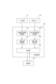
- FIG. 2 is a functional block diagram showing an example of the functional configuration of a control device 160.
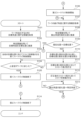
- 4 is a flowchart showing an example of processing of a control device 160.
- FIG. 13 is a functional block diagram showing another example of the functional configuration of the control device 160.
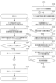
- 10 is a flowchart showing another example of the process of the control device 160.
- 10 is a flowchart showing another example of the process of the control device 160.
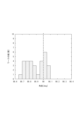
- 13 is a diagram showing the distribution of bending angles of a workpiece W1 bent by feeding back the position of a slide 130.
- FIG. 13 is a diagram showing the distribution of bending angles of a workpiece W1 that has been bent by feeding back the bending angle of the workpiece W1.
- FIG. 13 is a diagram showing the distribution of bending angles of a workpiece W1 bent by feeding back the position of a slide 130.
- FIG. 13 is a diagram showing the distribution of bending angles of a workpiece W1 that has been bent by feeding back the bending angle of the workpiece W1.
- FIG. 13 is a diagram showing the distribution of bending angles of a workpiece W1 bent by feeding back the position of a slide 130.
- FIG. 13 is a diagram showing the distribution of bending angles of a workpiece W1 that has been bent by feeding back the bending angle of the workpiece W1.
- FIG. 13 is a diagram showing the distribution of bending angles of a workpiece W1 that has been bent by feeding back the bending angle of the workpiece W1.
- FIG. 13 is a diagram showing the distribution of bending angles of a workpiece W1 bent by feeding back the position of a slide 130.
- FIG. 13 is a diagram showing the distribution of bending angles of a workpiece W1 that has been bent by feeding back the bending angle of the workpiece W1.
- FIG. 13 is a diagram showing the distribution of bending angles of a workpiece W1 bent by feeding back the position of a slide 130.
- FIG. 13 is a diagram showing the distribution of bending angles of a workpiece W1 that has been bent by feeding back the bending angle of the workpiece W1.
- FIG. 13 is a diagram showing the distribution of bending angles of a workpiece W1 bent by feeding back the position of a slide 130.
- FIG. 1 is a front view showing an example of the configuration of a press brake 100.
- the press brake 100 is a press machine used for bending a workpiece W1.
- the press brake 100 includes a frame 110, a drive unit 120, a slide 130, a back gauge 140, an angle sensor 150, and a control device 160.
- the frame 110 includes a crown 111, an upright 112, and a bed 113.
- the crown 111 is a part that houses the drive unit 120.
- the drive unit 120 is a mechanism that drives the slide 130.
- the drive unit 120 includes, for example, a servo motor that operates the slide 130, a servo valve, a servo amplifier, a feedback detector, and an electric braking device.
- the upright 112 is a part that holds the sliding part of the slide 130.
- the bed 113 is a part that serves as a base that receives press pressure.
- the upper surface of the bed has a structure that allows the attachment of a bolster BP.
- the bolster BP is attached to the upper surface of the bed 113 and is a base plate on which the lower die LT is attached.
- the upper surface of the bolster has a structure that allows the attachment of the lower die LT.
- the lower die LT is a tool that processes the workpiece W1 in combination with the upper die UT.
- the slide 130 is the part to which the upper die UT is attached and which moves back and forth.
- the slide 130 is also called a ram.
- the upper die UT is a tool that is combined with the lower die LT to machine the workpiece W1.
- the backgauge 140 is a tool that determines the position of the workpiece W1 at the rear side of the part where the workpiece W1 is to be bent.
- the backgauge 140 is also called a butt.
- the backgauge 140 is provided so as to be movable in the X direction on the XY plane, for example, by a mechanism not shown.
- the angle sensor 150 is a sensor that detects the bending angle of the workpiece W1.
- the angle sensor 150 is provided at a position in front of the lower die LT and at a position behind the lower die LT when viewed from the front.
- the angle sensor 150 is also provided so as to be movable in the X direction in the XY plane, for example, by a mechanism not shown.
- the control device 160 is a device that controls the movement of the slide 130.
- the control device 160 is electrically connected to the drive unit 120 and the angle sensor 150.
- the control device 160 receives a detection signal from the angle sensor 150 that can identify the bending angle of the workpiece W1.
- the control device 160 transmits a command signal to the drive unit 120 to drive the drive unit 120 to move the slide 130 to the target position.
- FIG. 2 is a functional block diagram showing an example of the functional configuration of the control device 160.
- the control device 160 includes a target angle information acquisition unit 161, a target position calculation unit 162, a detection angle information acquisition unit 163, a current position calculation unit 164, and a control unit 165.
- the target angle information acquisition unit 161 is a module that acquires information about the target angle when pressurizing the workpiece W1.
- the target angle information acquisition unit 161 acquires information about the target angle that is input using, for example, the input device 170.
- the input device 170 is a device for providing data, information, instructions, etc. to the main body of a device such as a computer.
- the target position calculation unit 162 is a module that calculates the target position to which the slide 130 is to be moved.
- the target position calculation unit 162 uses the information on the target angle acquired by the target angle information acquisition unit 161 to convert the target angle when pressurizing the workpiece W1 into the target position to which the slide 130 is to be moved.
- the detection angle information acquisition unit 163 is a module that acquires information related to the detection angle detected by the angle sensor 150.
- the detection angle information acquisition unit 163 acquires information related to the detection angle, for example, by sampling the output signal of the angle sensor 150.
- the current position calculation unit 164 is a module that calculates the current position of the slide 130.
- the current position calculation unit 164 converts the detection angle detected by the angle sensor 150 into the current position of the slide 130 corresponding to the detection angle, using information related to the detection angle acquired by the detection angle information acquisition unit 163.
- the control unit 165 is a module that controls the movement of the slide 130.
- the control unit 165 sends a command signal to the servo amplifier of the drive unit 120 to move the slide 130 to the target position.
- the control unit 165 shown in FIG. 2 refers to a feedback signal that indicates the position result when the slide 130 is controlled, which is output from the feedback detector of the drive unit 120.
- the control unit 165 executes a first feedback control that moves the slide 130 toward the initial target position until a specific condition is met. After the specific condition is met, the control unit 165 executes a second feedback control that corrects the stroke length to move the slide 130 to a position corresponding to the difference between the target position and the current position.
- the stroke length is the movement distance of the slide 130 in one process.
- the second feedback control is an example of the "feedback control" in this invention.
- FIG. 3 is a side view showing the workpiece W1 being pressed by the press brake 100.
- FIG. 4 is a side view showing the workpiece W1 being unloaded by the press brake 100.
- the workpiece W1 is bent by the slide 130 moving in the downward direction LD and being pressed between the upper die UT and the lower die LT.
- the slide 130 moves in the upward direction UD and the load is removed, the workpiece W1 springs back to the outside O1.
- Springback is the warping that occurs when the workpiece W1 is bent.
- the bending angle of the workpiece W1 after bending is changed by springback when the load is removed. Therefore, the target angle when pressurizing the workpiece W1 is set in anticipation of the change in angle due to springback.
- FIG. 5 is a flowchart showing an example of processing by the control device 160.
- the worker inputs information about the target angle using the input device ID to set the target angle when pressurizing the workpiece W1.
- the target angle information acquisition unit 161 of the control device 160 acquires information about the target angle input using the input device ID (S101).
- the target angle information acquisition unit 161 acquires, as information about the target angle, for example, a parameter indicating the target angle when pressurizing the workpiece W1.
- the target position calculation unit 162 of the control device 160 converts the target angle when pressurizing the workpiece W1 into a target position to which the slide 130 is moved (S102).
- the target position calculation unit 162 identifies the target angle based on the information about the target angle acquired by the target angle information acquisition unit 161.
- the target position calculation unit 162 converts the target angle into a target position, for example, by using a specific function.
- the target position calculation unit 162 uses the function disclosed in Japanese Patent No. 5737657 as the specific function.
- control unit 165 of the control device 160 executes a first feedback control to move the slide 130 toward the initial target position (S103).
- the control unit 165 transmits a command signal to the servo amplifier of the drive unit 120 to move the slide 130 toward the initial target position.
- control unit 165 determines whether the upper die UT attached to the slide 130 has hit the workpiece W1 (S104). In S104, the control unit 165 receives, for example, a feedback signal indicating the position result when the slide 130 is controlled from the feedback detector of the drive unit 120. Then, the control unit 165 determines whether the upper die UT has hit the workpiece W1 by referring to, for example, the predicted position of the slide 130 when the upper die UT hits the workpiece W1 and the feedback signal.
- the control unit 165 repeatedly executes the process of S104 every time a certain amount of time has elapsed, for example, by using an interval timer.
- the interval timer is a mechanism that notifies the user that a certain amount of time has elapsed.
- control unit 165 ends the first feedback control (S105).
- control device 160 starts the second feedback control (S106).
- the detection angle information acquisition unit 163 of the control device 160 acquires information related to the detection angle detected by the angle sensor 150 (S107).
- the detection angle information acquisition unit 163 acquires, as information related to the detection angle, for example, a parameter indicating the detection angle detected by the angle sensor 150.
- the current position calculation unit 164 of the control device 160 converts the detected angle into a current position of the slide 130 corresponding to the detected angle (S108).
- the current position calculation unit 164 converts the detected angle into a current position, for example, by using a specific function.
- the current position calculation unit 164 uses, as the specific function, the same function as that used by the target position calculation unit 162.
- the detection angle information acquisition unit 163 determines whether the current position of the slide 130 has reached the target position (S109).
- the control unit 165 compares the target position with the current position and calculates the difference between the target position and the current position (S110). In S110, the control unit 165 compares the target position calculated by the target position calculation unit 162 with the current position calculated by the current position calculation unit 164 and calculates the difference between the target position and the current position.
- the bending angle of the workpiece W1 is determined by the stroke length of the slide 130. However, even if the stroke length of the slide 130 is the same, the bending angle of the workpiece W1 varies due to differences in the plate thickness, material, and size of the workpiece W1. Also, even if the stroke length of the slide 130 is the same, the bending angle of the workpiece W1 varies due to the deflection of the frame 110, the deflection of the upper die UT, and the deflection of the lower die LT.
- control unit 165 corrects the stroke length to move the slide 130 to a position that corresponds to the difference between the target position and the current position (S111).
- control unit 165 moves the slide 130 using the corrected stroke length as a target (S112).
- control unit 165 sends a command signal to the servo amplifier of the drive unit 120 to move the slide 130 using the corrected stroke length as a target.
- control unit 165 determines whether a specific time has elapsed (S113). In S113, the control unit 165 determines whether a specific time has elapsed after starting control to move the slide 130 with the latest corrected stroke length as a target, for example.
- control unit 165 If the specific time has not elapsed (S113; NO), the control unit 165 repeatedly executes the process of S113 every time a certain time elapses, for example, by using an interval timer.
- control device 160 executes the processes from S107 onwards again.
- the control device 160 repeatedly executes the processes from S107 to S113 until the current position of the slide 130 becomes the target position.
- control device 160 ends the second feedback control (S114) and ends the control shown in the flowchart of FIG. 5.
- the press brake 100 of the above embodiment is used to bend the workpiece W1.
- the press brake 100 is equipped with a slide 130 that reciprocates with an upper die UT attached.
- the press brake 100 is equipped with a control device 160 that controls the movement of the slide 130.
- the press brake 100 is equipped with an angle sensor 150 that detects the bending angle of the workpiece W1.
- the control device 160 converts the target angle when pressurizing the workpiece W1 into a target position to which the slide 130 is moved.
- the control device 160 converts the detected angle detected by the angle sensor 150 into a current position of the slide 130 corresponding to the detected angle.
- the control device 160 compares the target position with the current position and executes a second feedback control that corrects the stroke length to move the slide 130 to a position corresponding to the difference between the target position and the current position.
- This type of press brake 100 converts the target angle into a target position, converts the detected angle into a current position, and compares the target position with the current position, so the accuracy of the second feedback control is high even if the difference between the target angle and the detected angle is small.
- the control device 160 of the above embodiment also converts the target angle into a target position using a specific function.
- the control device 160 of the above embodiment converts the detected angle into a current position using a specific function.
- the press brake 100 of this aspect has the same accuracy in converting the target angle into a target position and the same accuracy in converting the detected angle into a current position, improving the accuracy of the second feedback control.
- control device 160 of the above embodiment executes the second feedback control at specific time intervals.
- the press brake 100 of this aspect repeatedly executes the second feedback control, thereby improving accuracy.
- control device 160 in the above embodiment executes a first feedback control to move the slide 130 toward the initial target position until the upper die UT attached to the slide 130 hits the workpiece W1.
- the control device 160 executes a second feedback control after the upper die UT hits the workpiece W1.
- This aspect of the press brake 100 shortens the movement time of the slide 130 until the upper die UT hits the workpiece W1, thereby improving processing efficiency.
- FIG. 6 is a functional block diagram showing another example of the functional configuration of the control device 160.
- the control device 160 shown in FIG. 6 has a common functional configuration with the control device 160 shown in FIG. 2, except that the control unit 165 refers to the detection angle acquired by the detection angle information acquisition unit 163.
- FIG. 7 is a flowchart showing another example of the processing of the control device 160.
- the processing of the flowchart shown in FIG. 7 is the same as that of the flowchart shown in FIG. 5, except that the detected angle is referenced when the processing from S107 onwards is executed again.
- the control unit 165 determines whether the change in the detected angle has become a specific angle (S213). In S213, the control unit 165 determines whether the change in the detected angle has become a specific angle by referring to the detected angle acquired by the detected angle information acquisition unit 163. The control unit 165 determines whether the change in the detected angle has become a specific angle, for example, after starting control to move the slide 130 with the latest corrected stroke length as a target.
- control unit 165 If the change in the detected angle does not reach a specific angle (S213; NO), the control unit 165 repeatedly executes the process of S113 every time a certain period of time elapses, for example, by using an interval timer.
- control device 160 executes the processes from S107 onwards again.
- the control device 160 repeatedly executes the processes from S107 to S213 until the current position of the slide 130 reaches the target position.
- Fig. 8 is a flowchart showing another example of the process by the control device 160. The process of the flowchart shown in Fig. 8 is common to the flowchart shown in Fig. 5 except that the detected angle is referred to when the first feedback control is ended.
- control unit 165 determines whether the detection angle has become a predetermined angle (S304). In S304, the control unit 165 determines whether the detection angle has become a predetermined angle, for example, by referring to the detection angle acquired by the detection angle information acquisition unit 163.
- control unit 165 If the detected angle is not the specified angle (S304; NO), the control unit 165 repeatedly executes the process of S304 every time a certain period of time elapses, for example, by using an interval timer.
- the control unit 165 ends the first feedback control (S105).
- control device 160 of the above embodiment executes control to move the slide 130 toward the initial target position until the detected angle becomes the predetermined angle.
- the control device 160 starts the second feedback control after the detected angle becomes the predetermined angle.
- the press brake 100 of this aspect shortens the movement time of the slide 130 until the detected angle becomes the predetermined angle, thereby improving the efficiency of processing.
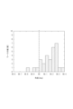
- Figure 9 is a diagram showing the distribution of bending angles of workpiece W1 bent by feeding back the position of slide 130.
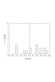
- Figure 10 is a diagram showing the distribution of bending angles of workpiece W1 bent by feeding back the bending angle of workpiece W1.
- the distributions shown in Figures 9 and 10 are both distributions of bending angles when 30 iron workpieces W1 of the same plate thickness and width are bent using a straight sword-shaped upper die UT with a target angle of 90 degrees.
- control for bending by feeding back the position of slide 130 is referred to as position control.
- control for bending by feeding back the bending angle of workpiece W1 is referred to as angle control.
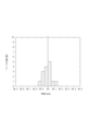
- Fig. 11 is a diagram showing the distribution of bending angles of workpiece W1 bent using position control.
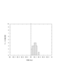
- Fig. 12 is a diagram showing the distribution of bending angles of workpiece W1 bent using angle control.
- the distributions shown in Figs. 11 and 12 are both distributions of bending angles when 30 aluminum workpieces W1 with the same plate thickness and width are bent using a straight-sword shaped upper die UT with a target angle of 90 degrees.
- Figure 13 is a diagram showing the distribution of bending angles of workpiece W1 bent by position control.
- Figure 14 is a diagram showing the distribution of bending angles of workpiece W1 bent by angle control.
- the distributions shown in Figures 13 and 14 are both distributions of bending angles when 15 iron workpieces W1 with the same plate thickness and width are bent using a gooseneck-shaped upper die UT.
- the target angle in bending by position control is 90.3 degrees.
- the target angle in bending by angle control is 90 degrees.
- Figure 15 is a diagram showing the distribution of bending angles of workpiece W1 bent using position control.
- Figure 16 is a diagram showing the distribution of bending angles of workpiece W1 bent using angle control.
- the distributions shown in Figures 15 and 16 are both distributions of bending angles when 20 workpieces W1 are bent along the roll marks of the workpiece W1 with a target angle of 90 degrees.
- the roll marks are in the rolling direction in the process of turning the workpiece W1 into a plate material.
- Figure 17 is a diagram showing the distribution of bending angles of workpieces W1 bent using position control.
- Figure 18 is a diagram showing the distribution of bending angles of workpieces W1 bent using angle control. The distributions shown in Figures 17 and 18 are both distributions of bending angles when 20 workpieces W1 are bent in a direction intersecting the roll grain of the workpieces W1 with a target angle of 90 degrees.
- the backgage 140 is provided so as to be movable in the X direction on the XY plane by a mechanism not shown.
- the backgage 140 may be immovable.
- the press brake 100 may be provided with a plurality of backgages 140 that are immovable in the X direction on the XY plane.
- the angle sensor 150 is provided at a position in front of the lower die LT and at a position behind the lower die LT when viewed from the front.
- the angle sensor 150 may be provided at either a position in front of the lower die LT or a position behind the lower die LT.
- the angle sensor 150 is arranged to be movable in the X direction in the XY plane by a mechanism not shown.
- the angle sensor 150 may be immovable.
- the press brake 100 may be provided with multiple angle sensors 150 that are immovable in the X direction in the XY plane.
- the control device 160 may send different command signals to the left and right control units 120 to drive the left and right crankshafts individually.
- the crankshaft is an axis that converts the rotational motion into the reciprocating motion of the slide 130.
- the bending process of the long workpiece W1 may cause the bending angle at one end to differ from the bending angle at the other end.
- control device 160 may use the detection result of the angle sensor 150 provided on one end to control the crankshaft on one end, and use the detection result of the angle sensor 150 provided on the other end to control the crankshaft on the other end.
- This type of press brake 100 can prevent the bending angle at one end from misaligning with the bending angle at the other end when bending a long workpiece W1.
- the target angle information acquisition unit 161 acquires parameters indicating the target angle when pressurizing the workpiece W1 as information regarding the target angle.
- the information acquired by the target angle information acquisition unit 161 need only be information regarding the target angle when pressurizing the workpiece W1, and is not limited to parameters indicating the target angle when pressurizing the workpiece W1.
- the target angle information acquisition unit 161 may acquire, for example, parameters that can be used to calculate the target angle when pressurizing the workpiece W1 as information regarding the target angle.
- the detection angle information acquisition unit 163 acquires a parameter indicating the detection angle detected by the angle sensor 150 as information regarding the detection angle.
- the information acquired by the detection angle information acquisition unit 163 may be information regarding the detection angle detected by the angle sensor 150, and is not limited to a parameter indicating the detection angle detected by the angle sensor 150.
- the detection angle information acquisition unit 163 may acquire, for example, a parameter capable of calculating the detection angle detected by the angle sensor 150 as information regarding the detection angle.
- control unit 165 may refer to the detected angle when terminating the first feedback control, similar to the process shown in FIG. 8.
- control device 160 repeatedly executes the second feedback control.
- control device 160 only needs to execute the second feedback control, and may execute the second feedback control only once.
Landscapes
- Engineering & Computer Science (AREA)
- Mechanical Engineering (AREA)
- Bending Of Plates, Rods, And Pipes (AREA)
Abstract
【課題】既知のプレスブレーキは、ワークを曲げる目標角度と実際の曲げ角度との差が小さくなるにつれて、スライドを移動させる真の目標位置に対する誤差が生じる可能性がある。 【解決手段】本発明の第1態様においては、ワークの曲げに使用するプレスブレーキが提供される。プレスブレーキは、上金型を取り付けて往復運動をするスライドを備える。プレスブレーキは、スライドの運動を制御する制御装置を備える。プレスブレーキは、ワークの曲げ角度を検出する角度センサを備える。制御装置は、ワークを加圧するときの目標角度を、スライドを移動させる目標位置に換算する。制御装置は、角度センサにより検出された検出角度を、検出角度に対応するスライドの現在位置に換算する。制御装置は、目標位置と現在位置とを比較し、目標位置と現在位置との差に対応する位置までスライドを移動させるべくストローク長さを訂正するフィードバック制御を実行する。
Description
本発明は、プレスブレーキ及びプレスブレーキの制御方法に関する。
プレスブレーキは、ワークの曲げ加工に使用される機械である。プレスブレーキによる曲げ加工は、ワークとなる金属の板のスプリングバックを伴う。スプリングバックは、精度不良や加工不良の要因となるため対策が欠かせない。
特許文献1に記載の技術は、パンチ及びダイから成る金型間にワークを介在させ、両金型を相対的に近接・離反動作させることによりワークを折曲げ加工する折曲げ加工装置に関する。折り曲げ加工装置は、金型駆動手段、角度検出手段、目標角指令手段及びファジィ制御手段を備える。金型駆動手段は、金型を相対的に接近・離反動作させる。角度検出手段は、両金型間で曲げ加工されるワークの曲げ角度を検出する。目標角指令手段は、ワークの曲げ角がスプリングバック後に製品角となるように予め設定された最終曲げ角を目標角として出力する。ファジィ制御手段は、目標角指令手段が出力した目標角と角度検出手段が検出したワークの曲げ角とを入力し、両角度の偏差に応じて指令値増量分を定め、ワークの曲げ角が目標角となるように金型駆動手段を制御する。
前述のとおり、特許文献1に記載の技術は、目標角とワークの曲げ角とを入力し、両角度の偏差に応じて指令値増量分を定め、ワークの曲げ角が目標角となるように金型駆動手段を制御する。ここで、目標角とワークの曲げ角との偏差は、ワークの曲げ角が目標角に近づくにつれて小さくなる。目標角とワークの曲げ角との偏差に応じて定められる指令値増量分は、両角度の偏差が小さくなるにつれて小さくなる。したがって、指令値増量分は、ワークの曲げ角と目標角に近づくにつれて、真に指令すべき増量分に対する誤差が生じる可能性がある。
本発明の第1態様においては、ワークの曲げに使用するプレスブレーキが提供される。プレスブレーキは、上金型を取り付けて往復運動をするスライドを備える。プレスブレーキは、スライドの運動を制御する制御装置を備える。プレスブレーキは、ワークの曲げ角度を検出する角度センサを備える。制御装置は、ワークを加圧するときの目標角度を、スライドを移動させる目標位置に換算する。制御装置は、角度センサにより検出された検出角度を、検出角度に対応するスライドの現在位置に換算する。制御装置は、目標位置と現在位置とを比較し、目標位置と現在位置との差に対応する位置までスライドを移動させるべくストローク長さを訂正するフィードバック制御を実行する。
本発明の第2態様においては、ワークの曲げに使用するプレスブレーキの制御方法が提供される。プレスブレーキの制御方法は、上金型を取り付けて往復運動をするスライドの運動を制御することを含む。プレスブレーキの制御方法は、角度センサによりワークの曲げ角度を検出することを含む。プレスブレーキの制御方法は、ワークを加圧するときの目標角度を、スライドを移動させる目標位置に換算する。プレスブレーキの制御方法は、角度センサにより検出された検出角度を、検出角度に対応するスライドの現在位置に換算する。プレスブレーキの制御方法は、目標位置と現在位置とを比較し、目標位置と現在位置との差に対応する位置までスライドを移動させるべくストローク長さを訂正するフィードバック制御を実行する。
上記態様のプレスブレーキは、目標角度を目標位置に換算し、検出角度を現在位置に換算し、目標位置と現在位置とを比較するので、目標角度と検出角度との差が小さくてもフィードバック制御の精度が高い。
制御装置は、特定関数を用いて目標角度を目標位置に換算してもよい。制御装置は、特定関数を用いて検出角度を現在位置に換算してもよい。この態様のプレスブレーキは、目標角度を目標位置に換算する精度と、検出角度を現在位置に換算する精度とが揃うので、フィードバック制御の精度が高まる。
制御装置は、特定時間おきに、フィードバック制御を実行してもよい。この態様のプレスブレーキは、繰り返しフィードバック制御を実行するので、より精度が高まる。
制御装置は、検出角度の変化量が特定角度となる度に、フィードバック制御を実行してもよい。この態様のプレスブレーキは、繰り返しフィードバック制御を実行するので、より精度が高まる。
制御装置は、上金型がワークに当たるまで当初の目標位置に向けてスライドを移動させる制御を実行してもよい。制御装置は、上金型がワークに当たった後にフィードバック制御を開始してもよい。この態様のプレスブレーキは、上金型がワークに当たるまでのスライドの移動時間が短くなるので、加工の効率が高まる。
制御装置は、検出角度が所定角度となるまで当初の目標位置に向けてスライドを移動させる制御を実行してもよい。制御装置は、検出角度が所定角度となった後にフィードバック制御を開始してもよい。この態様のプレスブレーキは、検出角度が所定角度となるまでのスライドの移動時間が短くなるので、加工の効率が高まる。
なお、上記発明の概要は、本発明の必要な特徴の全てを列挙したものではない。また、これらの特徴群のサブコンビネーションもまた、発明となり得る。
以下、発明の実施形態を通じて本発明を説明するが、以下の実施形態は、特許請求の範囲にかかる発明を限定するものではない。また、実施形態の中で説明されている特徴の組み合わせは、全てが発明の解決手段に必須であるとは限らない。
図1は、プレスブレーキ100の構成の一例を示す正面図である。プレスブレーキ100は、ワークW1の曲げ加工に使用されるプレス機械である。プレスブレーキ100は、フレーム110、駆動部120、スライド130、バックゲージ140、角度センサ150及び制御装置160を備える。
フレーム110は、クラウン111、アプライト112及びベッド113を備える。クラウン111は、駆動部120を内蔵する部分である。駆動部120は、スライド130を駆動する機構である。駆動部120は、例えば、スライド130を作動させるサーボモータ、サーボバルブ、サーボアンプ、フィードバック用検出器及び電気制動装置を含む。アプライト112は、スライド130のしゅう動部を保持する部分である。ベッド113は、プレス加圧を受ける基盤となる部分である。ベッド上面は、ボルスタBPを取り付け可能な構造を有する。ボルスタBPは、ベッド113上面に取り付けられ、下金型LTを取り付ける定盤である。ボルスタ上面は、下金型LTを取り付け可能な構造を有する。下金型LTは、上金型UTと組み合わせて、ワークW1を加工する工具である。
スライド130は、上金型UTを取り付けて往復運動をする部分である。スライド130は、ラムとも称される。上金型UTは、下金型LTと組み合わせて、ワークW1を加工する工具である。
バックゲージ140は、ワークW1を曲げる部分の奥側で、ワークW1の位置を決める工具である。バックゲージ140は、突当てとも称される。バックゲージ140は、例えば、図示しない機構にて、XY平面におけるX方向に移動可能に設けられる。
角度センサ150は、ワークW1の曲げ角度を検出するセンサである。角度センサ150は、例えば、正面視において、下金型LTよりも手前側の位置と、下金型LTよりも奥側の位置とにそれぞれ設けられる。また、角度センサ150は、例えば、図示しない機構にて、XY平面におけるX方向に移動可能に設けられる。
制御装置160は、スライド130の運動を制御する装置である。制御装置160は、駆動部120及び角度センサ150と電気的に接続される。制御装置160は、ワークW1の曲げ角度を特定可能な検出信号を角度センサ150から受信する。制御装置160は、目標位置までスライド130を移動させるべく駆動部120を駆動させる指令信号を駆動部120に送信する。
図2は、制御装置160の機能構成の一例を示す機能ブロック図である。制御装置160は、目標角度情報取得部161、目標位置算出部162、検出角度情報取得部163、現在位置算出部164及び制御部165を備える。
目標角度情報取得部161は、ワークW1を加圧するときの目標角度に関する情報を取得するモジュールである。目標角度情報取得部161は、例えば、入力装置170を利用して入力された、目標角度に関する情報を取得する。入力装置170は、コンピュータ等の機器本体にデータ、情報及び指示等を与えるための装置である。
目標位置算出部162は、スライド130を移動させる目標位置を算出するモジュールである。目標位置算出部162は、目標角度情報取得部161により取得された目標角度に関する情報用いて、ワークW1を加圧するときの目標角度を、スライド130を移動させる目標位置に換算する。
検出角度情報取得部163は、角度センサ150により検出された検出角度に関する情報を取得するモジュールである。検出角度情報取得部163は、例えば、角度センサ150の出力信号をサンプリングすることにより、検出角度に関する情報を取得する。
現在位置算出部164は、スライド130の現在位置を算出するモジュールである。現在位置算出部164は、検出角度情報取得部163により取得された検出角度に関する情報を用いて、角度センサ150により検出された検出角度を、検出角度に対応するスライド130の現在位置に換算する。
制御部165は、スライド130の運動を制御するモジュールである。制御部165は、目標位置までスライド130を移動させるべく、駆動部120のサーボアンプに指令信号を送信する。図2に示す制御部165は、駆動部120のフィードバック用検出器から出力される、スライド130を制御したときの位置の結果を示すフィードバック信号を参照する。制御部165は、特定条件が成立するまで、当初の目標位置に向けてスライド130を移動させる第1フィードバック制御を実行する。制御部165は、特定条件が成立した後に、目標位置と現在位置との差に対応する位置までスライド130を移動させるべくストローク長さを訂正する第2フィードバック制御を実行する。ストローク長さは、一工程におけるスライド130の運動距離である。第2フィードバック制御は、この発明における「フィードバック制御」の一例である。
図3は、プレスブレーキ100により加圧されたワークW1を示す側面図である。図4は、プレスブレーキ100により除荷されたワークW1を示す側面図である。
ワークW1は、スライド130が下方向LDに移動して上金型UTと下金型LTとに挟まれて加圧されることにより曲げ加工される。ワークW1は、スライド130が上方向UDに移動して除荷されると、外側O1にスプリングバックする。スプリングバックは、ワークW1を曲げたときに発生する反りである。
曲げ加工後のワークW1の曲げ角度は、除荷されることに伴い、スプリングバックにより変化した角度となる。したがって、ワークW1を加圧するときの目標角度は、スプリングバックによる角度の変化を見越して設定される。
図5は、制御装置160の処理の一例を示すフローチャートである。作業者は、ワークW1を曲げ加工するにあたり、ワークW1を加圧するときの目標角度を設定すべく、入力装置IDを利用して目標角度に関する情報を入力する。
まず、制御装置160の目標角度情報取得部161は、入力装置IDを利用して入力された、目標角度に関する情報を取得する(S101)。S101において、目標角度情報取得部161は、目標角度に関する情報として、例えば、ワークW1を加圧するときの目標角度を示すパラメータを取得する。
次に、制御装置160の目標位置算出部162は、ワークW1を加圧するときの目標角度を、スライド130を移動させる目標位置に換算する(S102)。S102において、目標位置算出部162は、目標角度情報取得部161により取得された目標角度に関する情報に基づいて目標角度を特定する。そして、目標位置算出部162は、例えば、特定関数を用いて、目標角度を目標位置に換算する。目標位置算出部162は、例えば、特定関数として、特許第5737657号公報に開示されている関数を用いる。
次に、制御装置160の制御部165は、当初の目標位置に向けてスライド130を移動させる第1フィードバック制御を実行する(S103)。第1フィードバック制御において、制御部165は、当初の目標位置に向けてスライド130を移動させる指令信号を、駆動部120のサーボアンプに送信する。
制御部165は、第1フィードバック制御を開始すると、スライド130に取り付けられた上金型UTがワークW1に当たったかを判定する(S104)。S104において、制御部165は、例えば、スライド130を制御したときの位置の結果を示すフィードバック信号を、駆動部120のフィードバック用検出器から受信する。そして、制御部165は、例えば、上金型UTがワークW1に当たるときのスライド130の予測位置とフィードバック信号とを参照して、上金型UTがワークW1に当たったかを判定する。
上金型UTがワークW1に当たっていない場合(S104;NO)、制御部165は、例えば、インターバルタイマーを用いて、一定の時間が経過するごとに、S104の処理を繰り返し実行する。インターバルタイマーは、一定の時間が経過するごとに、一定の時間が経過したことを知らせる仕組みである。
上金型UTがワークW1に当たった場合(S104;YES)、制御部165は、第1フィードバック制御を終了する(S105)。
次に、制御装置160は、第2フィードバック制御を開始する(S106)。
第2フィードバック制御において、制御装置160の検出角度情報取得部163は、角度センサ150により検出された検出角度に関する情報を取得する(S107)。S107において、検出角度情報取得部163は、検出角度に関する情報として、例えば、角度センサ150により検出された検出角度を示すパラメータを取得する。
次に、制御装置160の現在位置算出部164は、検出角度を、検出角度に対応するスライド130の現在位置に換算する(S108)。S108において、現在位置算出部164は、例えば、特定関数を用いて、検出角度を現在位置に換算する。現在位置算出部164は、例えば、特定関数として、目標位置算出部162により用いられる関数と同じ関数を用いる。
次に、検出角度情報取得部163は、スライド130の現在位置が目標位置となったかを判定する(S109)。
検出角度が目標角度となっていない場合(S109;NO)、制御部165は、目標位置と現在位置とを比較し、目標位置と現在位置との差を算出する(S110)。S110において、制御部165は、目標位置算出部162により算出された目標位置と、現在位置算出部164により算出された現在位置とを比較し、目標位置と現在位置との差を算出する。
ここで、ワークW1の曲げ角度は、スライド130のストローク長さによって決まる。しかし、ワークW1の曲げ角度は、スライド130のストローク長さが同じ長さであっても、ワークW1の板厚、材質及びサイズの違いに起因してばらつきが生じる。また、ワークW1の曲げ角度は、スライド130のストローク長さが同じ長さであっても、フレーム110のたわみ、上金型UTのたわみ及び下金型LTのたわみに起因してばらつきが生じる。
そこで、制御部165は、目標位置と現在位置との差に対応する位置までスライド130を移動させるべくストローク長さを訂正する(S111)。
次に、制御部165は、訂正後のストローク長さを目標にしてスライド130を移動させる(S112)。S112において、制御部165は、訂正されたストローク長さを目標にしてスライド130を移動させる指令信号を、駆動部120のサーボアンプに送信する。
次に、制御部165は、特定時間が経過したかを判定する(S113)。S113において、制御部165は、例えば、訂正後の最新のストローク長さを目標にしてスライド130を移動させる制御を開始した後に特定時間が経過したかを判定する。
特定時間が経過していない場合(S113;NO)、制御部165は、例えば、インターバルタイマーを用いて、一定の時間が経過するごとに、S113の処理を繰り返し実行する。
特定時間が経過した場合(S113;YES)、制御装置160は、S107以降の処理を再び実行する。制御装置160は、スライド130の現在位置が目標位置となるまで、S107からS113の処理を繰り返し実行する。
スライド130の現在位置が目標位置となると(S109;YES)、制御装置160は、第2フィードバック制御を終了し(S114)、図5のフローチャートに示す制御を終了する。
以上、上記実施形態のプレスブレーキ100は、ワークW1の曲げに使用する。プレスブレーキ100は、上金型UTを取り付けて往復運動をするスライド130を備える。プレスブレーキ100は、スライド130の運動を制御する制御装置160を備える。プレスブレーキ100は、ワークW1の曲げ角度を検出する角度センサ150を備える。制御装置160は、ワークW1を加圧するときの目標角度を、スライド130を移動させる目標位置に換算する。制御装置160は、角度センサ150により検出された検出角度を、検出角度に対応するスライド130の現在位置に換算する。制御装置160は、目標位置と現在位置とを比較し、目標位置と現在位置との差に対応する位置までスライド130を移動させるべくストローク長さを訂正する第2フィードバック制御を実行する。この態様のプレスブレーキ100は、目標角度を目標位置に換算し、検出角度を現在位置に換算し、目標位置と現在位置とを比較するので、目標角度と検出角度との差が小さくても第2フィードバック制御の精度が高い。
また、上記実施形態の制御装置160は、特定関数を用いて目標角度を目標位置に換算する。上記実施形態の制御装置160は、特定関数を用いて検出角度を現在位置に換算する。この態様のプレスブレーキ100は、目標角度を目標位置に換算する精度と、検出角度を現在位置に換算する精度とが揃うので、第2フィードバック制御の精度が高まる。
また、上記実施形態の制御装置160は、特定時間おきに、第2フィードバック制御を実行する。この態様のプレスブレーキ100は、繰り返し第2フィードバック制御を実行するので、より精度が高まる。
また、上記実施形態の制御装置160は、スライド130に取り付けられた上金型UTがワークW1に当たるまで当初の目標位置に向けてスライド130を移動させる第1フィードバック制御を実行する。制御装置160は、上金型UTがワークW1に当たった後に第2フィードバック制御を実行する。この態様のプレスブレーキ100は、上金型UTがワークW1に当たるまでのスライド130の移動時間が短くなるので、加工の効率が高まる。
図6は、制御装置160の機能構成の他の例を示す機能ブロック図である。図6に示す制御装置160は、制御部165が検出角度情報取得部163により取得された検出角度を参照する点を除き、図2に示す制御装置160と機能構成が共通する。
図7は、制御装置160の処理の他の例を示すフローチャートである。図7に示すフローチャートは、S107以降の処理を再び実行するにあたり、検出角度を参照する点を除き、図5に示すフローチャートと処理が共通する。
S112の処理を実行した後、制御部165は、検出角度の変化量が特定角度となったかを判定する(S213)。S213において、制御部165は、検出角度情報取得部163により取得された検出角度を参照して、検出角度の変化量が特定角度となったかを判定する。制御部165は、例えば、訂正後の最新のストローク長さを目標にしてスライド130を移動させる制御を開始した後に検出角度の変化量が特定角度となったかを判定する。
検出角度の変化量が特定角度となっていない場合(S213;NO)、制御部165は、例えば、インターバルタイマーを用いて、一定の時間が経過するごとに、S113の処理を繰り返し実行する。
検出角度の変化量が特定角度となった場合(S213;YES)、制御装置160は、S107以降の処理を再び実行する。制御装置160は、スライド130の現在位置が目標位置となるまで、S107からS213の処理を繰り返し実行する。
以上、上記実施形態の制御装置160は、検出角度の変化量が特定角度となる度に、第2フィードバック制御を実行する。この態様のプレスブレーキ100は、繰り返しフィードバック制御を実行するので、より精度が高まる。
図8は、制御装置160による処理の他の例を示すフローチャートである。図8に示すフローチャートは、第1フィードバック制御を終了するにあたり、検出角度を参照する点を除き、図5に示すフローチャートと処理が共通する。
図8は、制御装置160による処理の他の例を示すフローチャートである。図8に示すフローチャートは、第1フィードバック制御を終了するにあたり、検出角度を参照する点を除き、図5に示すフローチャートと処理が共通する。
制御部165は、第1フィードバック制御を開始すると、検出角度が所定角度となったかを判定する(S304)。S304において、制御部165は、例えば、検出角度情報取得部163により取得された検出角度を参照して、検出角度が所定角度となったかを判定する。
検出角度が所定角度となっていない場合(S304;NO)、制御部165は、例えば、インターバルタイマーを用いて、一定の時間が経過するごとに、S304の処理を繰り返し実行する。
検出角度が所定角度となった場合(S304;YES)、制御部165は、第1フィードバック制御を終了する(S105)。
以上、上記実施形態の制御装置160は、検出角度が所定角度となるまで当初の目標位置に向けてスライド130を移動させる制御を実行する。制御装置160は、検出角度が所定角度となった後に第2フィードバック制御を開始する。この態様のプレスブレーキ100は、検出角度が所定角度となるまでのスライド130の移動時間が短くなるので、加工の効率が高まる。
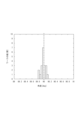
図9は、スライド130の位置をフィードバックして曲げ加工されたワークW1の曲げ角度の分布を示す図である。図10は、ワークW1の曲げ角度をフィードバックして曲げ加工されたワークW1の曲げ角度の分布を示す図である。図9及び図10に示す分布は、いずれも、同じ板厚及び板幅で鉄製の30個のワークW1を、直剣型の上金型UTを利用して、目標角度を90度として曲げ加工したときの曲げ角度の分布である。以下の説明において、スライド130の位置をフィードバックして曲げ加工する制御は、位置制御と称される。一方、ワークW1の曲げ角度をフィードバックして曲げ加工する制御は、角度制御と称される。
図9に示すように、位置制御により曲げ加工された30個のワークW1のうち、曲げ角度がほぼ目標角度となったワークW1の個数は、10個であった。図10に示すように、角度制御により曲げ加工された30個のワークW1のうち、曲げ角度がほぼ目標角度となったワークW1の個数は、18個であった。図9及び図10に示す分布から明らかなように、鉄製のワークW1を、直剣型の上金型UTを利用して曲げ加工する場合、角度制御による曲げ加工は、位置制御による曲げ加工よりも精度が高い。
図11は、位置制御により曲げ加工されたワークW1の曲げ角度の分布を示す図である。図12は、角度制御により曲げ加工されたワークW1の曲げ角度の分布を示す図である。図11及び図12に示す分布は、いずれも、同じ板厚及び板幅でアルミ製の30個のワークW1を、直剣型の上金型UTを利用して、目標角度を90度として曲げ加工したときの曲げ角度の分布である。
図11に示すように、位置制御により曲げ加工された30個のワークW1のうち、曲げ角度がほぼ目標角度となったワークW1の個数は、4個であった。図12に示すように、角度制御により曲げ加工された30個のワークW1のうち、曲げ角度がほぼ目標角度となったワークW1の個数は、15個であった。図11及び図12に示す分布から明らかなように、アルミ製のワークW1を、直剣型の上金型UTを利用して曲げ加工する場合、角度制御による曲げ加工は、位置制御による曲げ加工よりも精度が高い。
図13は、位置制御により曲げ加工されたワークW1の曲げ角度の分布を示す図である。図14は、角度制御により曲げ加工されたワークW1の曲げ角度の分布を示す図である。図13及び図14に示す分布は、いずれも、同じ板厚及び板幅で鉄製の15個のワークW1を、グースネック型の上金型UTを利用して曲げ加工したときの曲げ角度の分布である。位置制御による曲げ加工における目標角度は、90.3度である。角度制御による曲げ加工における目標角度は、90度である。
図13に示すように、位置制御により曲げ加工された15個のワークW1のうち、曲げ角度がほぼ目標角度となったワークW1の個数は、2個であった。図14に示すように、角度制御により曲げ加工された15個のワークW1のうち、曲げ角度がほぼ目標角度となったワークW1の個数は、9個であった。図13及び図14に示す分布から明らかなように、グースネック型の上金型UTを利用して曲げ加工する場合、角度制御による曲げ加工は、位置制御による曲げ加工よりも精度が高い。
図15は、位置制御により曲げ加工されたワークW1の曲げ角度の分布を示す図である。図16は、角度制御により曲げ加工されたワークW1の曲げ角度の分布を示す図である。図15及び図16に示す分布は、いずれも、20個のワークW1を、目標角度を90度として、ワークW1のロール目に沿って曲げ加工したときの曲げ角度の分布である。ロール目は、ワークW1を板材とする工程における、圧延方向である。
図15に示すように、位置制御により曲げ加工された20個のワークW1のうち、曲げ角度がほぼ目標角度となったワークW1の個数は、2個であった。図16に示すように、角度制御により曲げ加工された20個のワークW1のうち、曲げ角度がほぼ目標角度となったワークW1の個数は、10個であった。図15及び図16に示す分布から明らかなように、ワークW1のロール目に沿って曲げ加工する場合、角度制御による曲げ加工は、位置制御による曲げ加工よりも精度が高い。
図17は、位置制御により曲げ加工されたワークW1の曲げ角度の分布を示す図である。図18は、角度制御により曲げ加工されたワークW1の曲げ角度の分布を示す図である。図17及び図18に示す分布は、いずれも、20個のワークW1を、目標角度を90度として、ワークW1のロール目に交差する方向に沿って曲げ加工したときの曲げ角度の分布である。
図17に示すように、位置制御により曲げ加工された20個のワークW1のうち、曲げ角度がほぼ目標角度となったワークW1の個数は、0個であった。図18に示すように、角度制御により曲げ加工された20個のワークW1のうち、曲げ角度がほぼ目標角度となったワークW1の個数は、7個であった。図17及び図18に示す分布から明らかなように、ワークW1のロール目に沿って曲げ加工する場合、角度制御による曲げ加工は、位置制御による曲げ加工よりも精度が高い。
以上、本発明について実施形態を用いて説明したが、本発明の技術的範囲は、上記実施形態に記載の範囲には限定されない。上記実施形態に、多様な変更又は改良を加えることが可能であることは、当業者に明らかである。そのような変更又は改良を加えた形態も本発明の技術的範囲に含まれ得ることは、特許請求の範囲の記載から明らかである。
上記実施形態において、バックゲージ140は、図示しない機構にて、XY平面におけるX方向に移動可能に設けられる。しかし、バックゲージ140は、移動不能であってもよい。例えば、プレスブレーキ100は、XY平面におけるX方向において、移動不能な複数のバックゲージ140を備えてもよい。
上記実施形態において、角度センサ150は、正面視において、下金型LTよりも手前側の位置と、下金型LTよりも奥側の位置とにそれぞれ設けられる。しかし、角度センサ150は、下金型LTよりも手前側の位置と、下金型LTよりも奥側の位置とのうち、いずれか一方の位置に設けられてもよい。
上記実施形態において、角度センサ150は、図示しない機構にて、XY平面におけるX方向に移動可能に設けられる。しかし、角度センサ150は、移動不能であってもよい。例えば、プレスブレーキ100は、XY平面におけるX方向において、移動不能な複数の角度センサ150を備えてもよい。複数の角度センサ150を備える場合、制御装置160は、左右のクランク軸を個別に駆動させるべく、左右の制御部120に対して互いに異なる指令信号を送信してもよい。クランク軸は、回転運動をスライド130の往復運動に変える軸である。ここで、長物のワークW1の曲げ加工は、一端側における曲げ角度と、他端側における曲げ角度とがずれてしまう可能性がある。制御装置160は、例えば、一端側に設けられた角度センサ150の検出結果を利用して一端側のクランク軸を制御し、他端側に設けられた角度センサ150の検出結果を利用して他端側のクランク軸を制御すればよい。この態様のプレスブレーキ100は、長尺のワークW1を曲げ加工したときに、一端側における曲げ角度と他端側における曲げ角度とがずれてしまうことを抑制できる。
上記実施形態において、目標角度情報取得部161は、目標角度に関する情報として、ワークW1を加圧するときの目標角度を示すパラメータを取得する。しかし、目標角度情報取得部161が取得する情報は、ワークW1を加圧するときの目標角度に関する情報であればよく、ワークW1を加圧するときの目標角度を示すパラメータに限らない。目標角度情報取得部161は、例えば、目標角度に関する情報として、ワークW1を加圧するときの目標角度を算出可能なパラメータを取得してもよい。
上記実施形態において、検出角度情報取得部163は、検出角度に関する情報として、角度センサ150により検出された検出角度を示すパラメータを取得する。しかし、検出角度情報取得部163が取得する情報は、角度センサ150により検出された検出角度に関する情報であればよく、角度センサ150により検出された検出角度を示すパラメータに限らない。検出角度情報取得部163は、例えば、検出角度に関する情報として、角度センサ150により検出された検出角度を算出可能なパラメータを取得してもよい。
図7に示す処理において、制御部165は、図8に示す処理と同じように、第1フィードバック制御を終了するにあたり、検出角度を参照してもよい。
上記実施形態において、制御装置160は、第2フィードバック制御を繰り返し実行する。しかし、制御装置160は、第2フィードバック制御を実行すればよく、一度だけ第2フィードバック制御を実行してもよい。
特許請求の範囲、明細書及び図面中において示した装置及び方法における動作、手順、ステップ及び段階等の各処理の実行順序は、特段「より前に、」、「先立って」等と明示していない。また、各処理の実行順序は、前の処理の出力を後の処理で用いるのでない限り、任意の順序で実現し得ることに留意すべきである。特許請求の範囲、明細書及び図面中の動作フローに関して、便宜上「まず、」、「次に、」等を用いた説明は、この順序で実施することが必須であることを意味するものではない。また、法令で許容される限りにおいて、日本特許出願である特願2023-103495の開示を援用して本文の記載の一部とする。
100 プレスブレーキ、110 フレーム、111 クラウン、112 アプライト、113 ベッド、120 駆動部、130 スライド、140 バックゲージ、150 角度センサ、160 制御装置、161 目標角度情報取得部、162 目標位置算出部、163 検出角度情報取得部、164 現在位置算出部、165 制御部、170 入力装置、BP ボルスタ、LD 下方向、LT 下金型、O1 外側、UD 上方向、UT 上金型、W1 ワーク
Claims (7)
- ワークの曲げ加工に使用されるプレスブレーキであって、
上金型を取り付けて往復運動をするスライドと、
前記スライドの運動を制御する制御装置と、
ワークの曲げ角度を検出する角度センサと、を備え、
前記制御装置は、
ワークを加圧するときの目標角度を、前記スライドを移動させる目標位置に換算し、
前記角度センサにより検出された検出角度を、前記検出角度に対応する前記スライドの現在位置に換算し、
前記目標位置と前記現在位置とを比較し、前記目標位置と前記現在位置との差に対応する位置まで前記スライドを移動させるべくストローク長さを訂正するフィードバック制御を実行する、プレスブレーキ。 - 前記制御装置は、
特定関数を用いて前記目標角度を前記目標位置に換算し、
前記特定関数を用いて前記検出角度を前記現在位置に換算する、請求項1に記載のプレスブレーキ。 - 前記制御装置は、特定時間おきに前記フィードバック制御を実行する、請求項1に記載のプレスブレーキ。
- 前記制御装置は、前記検出角度の変化量が特定角度となる度に前記フィードバック制御を実行する、請求項1に記載のプレスブレーキ。
- 前記制御装置は、
前記上金型がワークに当たるまで当初の前記目標位置に向けて前記スライドを移動させる制御を実行し、
前記上金型がワークに当たった後に前記フィードバック制御を実行する、請求項1に記載のプレスブレーキ。 - 前記制御装置は、
前記検出角度が所定角度となるまで当初の前記目標位置に向けて前記スライドを移動させる制御を実行し、
前記検出角度が前記所定角度となった後に前記フィードバック制御を開始する、請求項1に記載のプレスブレーキ。 - ワークの曲げ加工に使用されるプレスブレーキの制御方法であって、
上金型を取り付けて往復運動をするスライドの運動を制御することと、
角度センサによりワークの曲げ角度を検出することと、を含み、
ワークを加圧するときの目標角度を、前記スライドを移動させる目標位置に換算し、
前記角度センサにより検出された検出角度を、前記検出角度に対応する前記スライドの現在位置に換算し、
前記目標位置と前記現在位置とを比較し、前記目標位置と前記現在位置との差に対応する位置まで前記スライドを移動させるべくストローク長さを訂正するフィードバック制御を開始する、プレスブレーキの制御方法。
Priority Applications (1)
| Application Number | Priority Date | Filing Date | Title |
|---|---|---|---|
| JP2025527544A JPWO2024262174A1 (ja) | 2023-06-23 | 2024-05-08 |
Applications Claiming Priority (2)
| Application Number | Priority Date | Filing Date | Title |
|---|---|---|---|
| JP2023-103495 | 2023-06-23 | ||
| JP2023103495 | 2023-06-23 |
Publications (1)
| Publication Number | Publication Date |
|---|---|
| WO2024262174A1 true WO2024262174A1 (ja) | 2024-12-26 |
Family
ID=93935517
Family Applications (1)
| Application Number | Title | Priority Date | Filing Date |
|---|---|---|---|
| PCT/JP2024/017126 Ceased WO2024262174A1 (ja) | 2023-06-23 | 2024-05-08 | プレスブレーキ及びプレスブレーキの制御方法 |
Country Status (2)
| Country | Link |
|---|---|
| JP (1) | JPWO2024262174A1 (ja) |
| WO (1) | WO2024262174A1 (ja) |
Citations (5)
| Publication number | Priority date | Publication date | Assignee | Title |
|---|---|---|---|---|
| JPS62274101A (ja) * | 1986-05-23 | 1987-11-28 | Amada Co Ltd | 油圧機器におけるラム位置決め方法 |
| JPH01210124A (ja) * | 1988-02-18 | 1989-08-23 | Matsushita Electric Works Ltd | 曲げ加工機の曲げ角度制御方法 |
| JPH08300048A (ja) * | 1995-04-27 | 1996-11-19 | Komatsu Ltd | 曲げ加工機 |
| JPH10118717A (ja) * | 1996-10-14 | 1998-05-12 | Komatsu Ltd | 折曲げ機における折曲げ角度補正方法および補正装置 |
| JP2006224144A (ja) * | 2005-02-17 | 2006-08-31 | Amada Co Ltd | 板材折曲げ加工方法及び板材折曲げ加工機 |
-
2024
- 2024-05-08 WO PCT/JP2024/017126 patent/WO2024262174A1/ja not_active Ceased
- 2024-05-08 JP JP2025527544A patent/JPWO2024262174A1/ja active Pending
Patent Citations (5)
| Publication number | Priority date | Publication date | Assignee | Title |
|---|---|---|---|---|
| JPS62274101A (ja) * | 1986-05-23 | 1987-11-28 | Amada Co Ltd | 油圧機器におけるラム位置決め方法 |
| JPH01210124A (ja) * | 1988-02-18 | 1989-08-23 | Matsushita Electric Works Ltd | 曲げ加工機の曲げ角度制御方法 |
| JPH08300048A (ja) * | 1995-04-27 | 1996-11-19 | Komatsu Ltd | 曲げ加工機 |
| JPH10118717A (ja) * | 1996-10-14 | 1998-05-12 | Komatsu Ltd | 折曲げ機における折曲げ角度補正方法および補正装置 |
| JP2006224144A (ja) * | 2005-02-17 | 2006-08-31 | Amada Co Ltd | 板材折曲げ加工方法及び板材折曲げ加工機 |
Also Published As
| Publication number | Publication date |
|---|---|
| JPWO2024262174A1 (ja) | 2024-12-26 |
Similar Documents
| Publication | Publication Date | Title |
|---|---|---|
| US4408471A (en) | Press brake having spring-back compensating adaptive control | |
| US11565295B2 (en) | Angle measurement system | |
| CN101678430B (zh) | 薄板的冲压成形装置以及冲压成形方法 | |
| CN111822580B (zh) | 用于操作精细冲裁系统的方法 | |
| US7757526B2 (en) | Method for changing force control gain and die cushion control apparatus | |
| CN101310890A (zh) | 冲压连接方法及压机 | |
| EP1914019A1 (en) | Press brake and related workpiece bending procedure | |
| JP2004520939A5 (ja) | ||
| EP1741500B1 (en) | Die cushion mechanism, and device and method for controlling the same | |
| EP1277529B1 (en) | Bending method and bending apparatus | |
| WO2024262174A1 (ja) | プレスブレーキ及びプレスブレーキの制御方法 | |
| US4075451A (en) | Butt welding apparatus | |
| CN111151592B (zh) | 一种基于pci-e引脚冲压成型设备的误差检测调整方法 | |
| JP3870262B2 (ja) | スピニング加工方法および装置 | |
| JP3720099B2 (ja) | 曲げ加工機における板厚検出方法およびその装置並びに曲げ加工方法および曲げ加工機 | |
| JP7609645B2 (ja) | プレスシステム及びプレスシステムの制御方法 | |
| JP2713773B2 (ja) | 折曲げ加工機の制御方法 | |
| JP6894951B2 (ja) | 曲げ加工方法及び曲げ加工システム | |
| JP4878806B2 (ja) | ダイ金型,折曲げ加工方法及び装置 | |
| JPH0815624B2 (ja) | 曲げ機械 | |
| CN114282610B (zh) | 一种压力机工作能量的检测匹配方法 | |
| JP2006075880A (ja) | しごき曲げ機における曲げ加工方法及びその装置 | |
| JPH0985350A (ja) | 折曲げ加工機における曲げ加工方法およびこの方法を用いた折曲げ加工機 | |
| JPH0354012B2 (ja) | ||
| JP4002464B2 (ja) | 張力制御を用いた薄板のプレス加工方法及び装置 |
Legal Events
| Date | Code | Title | Description |
|---|---|---|---|
| 121 | Ep: the epo has been informed by wipo that ep was designated in this application |
Ref document number: 24825583 Country of ref document: EP Kind code of ref document: A1 |
|
| ENP | Entry into the national phase |
Ref document number: 2025527544 Country of ref document: JP Kind code of ref document: A |
|
| NENP | Non-entry into the national phase |
Ref country code: DE |