WO2024253160A1 - 磁性体および絶縁体の二層膜,トンネル磁気抵抗素子,及び磁気メモリ - Google Patents
磁性体および絶縁体の二層膜,トンネル磁気抵抗素子,及び磁気メモリ Download PDFInfo
- Publication number
- WO2024253160A1 WO2024253160A1 PCT/JP2024/020707 JP2024020707W WO2024253160A1 WO 2024253160 A1 WO2024253160 A1 WO 2024253160A1 JP 2024020707 W JP2024020707 W JP 2024020707W WO 2024253160 A1 WO2024253160 A1 WO 2024253160A1
- Authority
- WO
- WIPO (PCT)
- Prior art keywords
- layer
- insulator
- sio
- antiferromagnetic
- film
- Prior art date
- Legal status (The legal status is an assumption and is not a legal conclusion. Google has not performed a legal analysis and makes no representation as to the accuracy of the status listed.)
- Ceased
Links
Images


Classifications
-
- H—ELECTRICITY
- H10—SEMICONDUCTOR DEVICES; ELECTRIC SOLID-STATE DEVICES NOT OTHERWISE PROVIDED FOR
- H10N—ELECTRIC SOLID-STATE DEVICES NOT OTHERWISE PROVIDED FOR
- H10N50/00—Galvanomagnetic devices
- H10N50/10—Magnetoresistive devices
-
- H—ELECTRICITY
- H10—SEMICONDUCTOR DEVICES; ELECTRIC SOLID-STATE DEVICES NOT OTHERWISE PROVIDED FOR
- H10B—ELECTRONIC MEMORY DEVICES
- H10B61/00—Magnetic memory devices, e.g. magnetoresistive RAM [MRAM] devices
-
- H—ELECTRICITY
- H10—SEMICONDUCTOR DEVICES; ELECTRIC SOLID-STATE DEVICES NOT OTHERWISE PROVIDED FOR
- H10D—INORGANIC ELECTRIC SEMICONDUCTOR DEVICES
- H10D48/00—Individual devices not covered by groups H10D1/00 - H10D44/00
- H10D48/40—Devices controlled by magnetic fields
-
- H—ELECTRICITY
- H10—SEMICONDUCTOR DEVICES; ELECTRIC SOLID-STATE DEVICES NOT OTHERWISE PROVIDED FOR
- H10N—ELECTRIC SOLID-STATE DEVICES NOT OTHERWISE PROVIDED FOR
- H10N50/00—Galvanomagnetic devices
- H10N50/01—Manufacture or treatment
-
- H—ELECTRICITY
- H10—SEMICONDUCTOR DEVICES; ELECTRIC SOLID-STATE DEVICES NOT OTHERWISE PROVIDED FOR
- H10N—ELECTRIC SOLID-STATE DEVICES NOT OTHERWISE PROVIDED FOR
- H10N50/00—Galvanomagnetic devices
- H10N50/80—Constructional details
- H10N50/85—Materials of the active region
-
- H—ELECTRICITY
- H10—SEMICONDUCTOR DEVICES; ELECTRIC SOLID-STATE DEVICES NOT OTHERWISE PROVIDED FOR
- H10B—ELECTRONIC MEMORY DEVICES
- H10B61/00—Magnetic memory devices, e.g. magnetoresistive RAM [MRAM] devices
- H10B61/20—Magnetic memory devices, e.g. magnetoresistive RAM [MRAM] devices comprising components having three or more electrodes, e.g. transistors
- H10B61/22—Magnetic memory devices, e.g. magnetoresistive RAM [MRAM] devices comprising components having three or more electrodes, e.g. transistors of the field-effect transistor [FET] type
Definitions
- the present disclosure relates to a two layer film of a magnetic body and an insulator, a tunnel magnetoresistive element, and a magnetic memory.
- WO2022/220251 discloses that by sandwiching Ta between the Mn 3 Sn and the contact layer of an insulator, the roughness of the interface is suppressed and smoothed, and the read signal of a magnetic memory element is enhanced.
- a tunnel magnetoresistance element can be obtained by using an antiferromagnetic layer such as Mn 3 Sn as a ferromagnetic layer and sandwiching an insulating layer such as MgO between two antiferromagnetic layers.
- the present invention aims to obtain a tunneling magnetoresistance element, a double-layered film of a magnetic material and an insulator, which can obtain a relatively large tunneling magnetoresistance ratio. It also aims to obtain a magnetic memory which can obtain a relatively large read signal.
- the double-layered film of magnetic material and insulator has a hexagonal crystal structure and includes an antiferromagnetic layer with at least one surface being the (10-10) surface of an antiferromagnetic material, and an insulator layer containing a compound made of two, three, or four types of atoms stacked on the (10-10) surface.
- the bilayer film of magnetic material and insulator has a hexagonal crystal structure and includes an antiferromagnetic layer with at least one surface being the (0001) surface of an antiferromagnetic material, and an insulator layer containing a compound consisting of two, three, or four types of atoms stacked on the (0001) surface.
- the tunneling magnetoresistance element has a second antiferromagnetic film layer stacked on the bilayer insulator.
- the magnetic memory includes a plurality of the tunneling magnetoresistance elements described above.
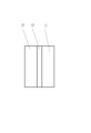
- FIG. 1 is a cross-sectional view showing one embodiment of a two-layer film of a magnetic material and an insulator.
- 1 is a cross-sectional view showing an embodiment of a tunneling magnetoresistive element.
- 5A to 5C are cross-sectional views illustrating the operation of a tunnel magnetoresistive element.
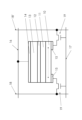
- FIG. 2 is a circuit diagram of one embodiment of a magnetic memory.
- ranges When amounts, concentrations, or other values or parameters are given herein as ranges, and/or the description includes a list of upper and lower values, this is understood to specifically disclose all integers and fractions within the given range, as well as all ranges formed from any pair of any upper and lower values, whether or not a narrower range is separately disclosed.
- range of numerical values When a range of numerical values is given herein, unless otherwise stated, the range is intended to include all integers and fractions within the range, as well as its endpoints.
- the range of 1 to 10 fully describes and includes the independent subrange 3.4 to 7.2, as well as the listing of the values 1, 4, 6, and 10.
- a relatively large tunnel magnetoresistance (TMR) ratio is obtained by using a specific material for the insulating layer depending on the surface orientation of the antiferromagnetic layer. Therefore, when this tunnel magnetoresistance element is used in a magnetic memory, a relatively large read signal is obtained.
- Figure 1 is a cross-sectional view showing one embodiment of a two-layer film of a magnetic material and an insulator.
- An insulator layer 12 is laminated on an antiferromagnetic layer 11.
- FIG. 2 is a cross-sectional view showing one embodiment of a tunnel magnetoresistance element.
- An insulating layer 12 is laminated on an antiferromagnetic layer 11, and a second antiferromagnetic layer 13 is further laminated on the insulating layer 12.
- the materials of the antiferromagnetic layer 11 and the second antiferromagnetic layer 13 may be the same or different.
- Preferred materials include at least one selected from Mn 3 Sn, Mn 3 Ge, Mn 3 Ga, and Mn 3 A x B 1-x (A and B are each one selected from Sn, Ge, and Ga, 0 ⁇ x ⁇ 1). These crystals have cluster magnetic octupole polarized spins, and the net spin polarization defined by the magnetic octupole can be rotated by applying a magnetic field or passing a current.
- the material of the insulator laminated on the (10-10) plane is preferably one shown in Table 1
- the material of the insulating layer laminated on the (0001) plane is preferably one shown in Table 2.
- the more preferable material for the insulating layer 12 is shown in Table 3
- the more preferable material for the insulating layer 12 is shown in Table 4.
- the thickness of the antiferromagnetic layer 11 and the second antiferromagnetic layer 13 is, for example, 0.5 nm to 40 nm, preferably 0.5 nm to 30 nm, and more preferably 0.5 nm to 20 nm.
- the thickness of the insulator layer 12 is, for example, 0.5 nm to 5 nm, preferably 0.5 nm to 4 nm, and more preferably 1 nm to 3 nm.
- the inventors of this disclosure discovered that a relatively large TMR ratio can be obtained by using a specific material for the insulator layer depending on the surface orientation of the antiferromagnetic layer.
- the crystal structures of the materials published in The Materials Project are obtained, and for each material, a material is searched for that has a "crystal plane with a similar shape" to each of the hexagonal (10-10) and (0001) planes used in the antiferromagnetic layer.
- the "crystal planes having a similar shape” are those that can be made to coincide by lattice deformation within a certain range of the (10-10) and (0001) planes of any of Mn 3 Sn, Mn 3 Ge, Mn 3 Ga, and Mn 3 A x B 1-x .
- the (10-10) and (0001) planes are parallelograms, with sides of lengths a and b (a ⁇ b) connected at an angle ⁇ .
- the range of lattice deformation is -0.07 ⁇ p, q ⁇ 0.07 and -0.07 ⁇ p+q ⁇ 0.07, assuming that a, b is transformed from a ⁇ (1+p), b ⁇ (1+q).
- the deformation of the angle ⁇ is within ⁇ 3.5%.
- materials are selected that have two, three, or four types of constituent atoms, a band gap of 0.5 eV or more to ensure insulation, negative formation energy, and an energy above the convex hull value of 0.15 eV/atom or less, and that are registered in the ICSD (Inorganic Crystal Structure Database).
- At least one of Mn 3 Sn, Mn 3 Ge, Mn 3 Ga, and Mn 3 A x B 1-x is selected to perform a simulation calculation for creating a two-layer structure of insulator layer/magnetic layer/vacuum surface.
- the surface to be laminated here is the (10-10) surface of the magnetic layer for the insulators in Table 1, and the (0001) surface of the magnetic layer for the insulators in Table 2.
- first-principles calculations are used to set the distance between the layers and the position of the layer lamination surface so that the energy is minimized, and then local structure optimization of the internal coordinates of atoms in layers 2-4 near the interface is performed.
- the interfacial energy of the bilayer structure obtained above is calculated by first-principles calculations. This makes it possible to identify insulators that can stably form an interface with an antiferromagnetic layer.
- the energy of each of the structures of the insulator alone, the magnetic material alone, the surface of the insulator, and the surface of the magnetic material is calculated and subtracted from the bilayer structure.
- the thickness of each layer is set to 0.8 nm or more.
- Quantum ESPRESSO Quantum ESPRESSO
- PBE Perdew, Burke, and Ernzerhof
- USPP ultrasoft pseudopotential
- Materials with an interfacial energy of 2 J/ m2 or less obtained as described above are judged to be insulating materials that can stably form a laminated structure with a magnetic material.
- the simulation target is a structure of insulating layer/magnetic layer A/insulating layer/magnetic layer B, which is created by repeating the two-layer structure twice, after removing the vacuum layer. Periodic boundary conditions are imposed on this four-layer structure, and the tunnel conductivity is calculated after taking into account magnetism, and the TMR ratio is estimated.
- the PWCOND package of the QE package is used, which calculates ballistic transport along the stacking direction (z direction) by solving a scattering problem for the Bloch wave function obtained by DFT calculation.
- the k (kx, ky) point mesh on the xy plane is changed from 32 x 32 to 64 x 64, and the transmittance T is calculated for each relative angle between the magnetic configurations (cluster magnetic octupole moments of the two magnetic layers). This is the maximum (minimum) value of the transmittance.
- Tmax min
- TMR can be evaluated as (Tmax-Tmin)/Tmin.
- the band gap of the compound contained in the insulator layer is 0.5 eV or more, in a more preferred embodiment, 0.8 eV or more, and in an even more preferred embodiment, 1.5 eV or more.
- the formation energy of the compound contained in the insulator layer is negative and the energy above the convex hull value is 0.15 eV/atom or less. In a more preferred embodiment, the energy above the convex hull value of the compound contained in the insulator layer is 0.02 eV/atom or less.
- the interfacial energy of the interface between the two-layer film of the magnetic material and the insulator calculated by first-principles calculation is 2 J/m 2 or less. In a more preferred embodiment, the interfacial energy of the interface between the two-layer film of the magnetic material and the insulator calculated by first-principles calculation is 1 J/m 2 or less.
- the TMR ratio of the tunneling magnetoresistance element is 300% or more. In a more preferred embodiment, the TMR ratio of the tunneling magnetoresistance element is 1000% or more.
- the insulating layer and the two antiferromagnetic layers are in direct contact.
- one or more separate layers are interposed between the insulating layer and the antiferromagnetic layer.
- the separate layer disposed between the antiferromagnetic layer and the insulating layer is not particularly limited as long as it can be formed by a known film formation method such as sputtering or epitaxial growth (MBE, MOCVD, etc.).
- examples of the one or more separate layers include layers containing Ta or Ru as materials.
- the double-layered film of magnetic material and insulator and the tunnel magnetoresistance element can be fabricated by the following steps: (1) creating an antiferromagnetic layer 11, (2) laminating an insulator layer 12 onto the antiferromagnetic layer 11, and (3) laminating a second antiferromagnetic layer 13 onto the insulator layer 12.
- the antiferromagnetic layer 11 can be created by depositing the material disclosed herein on a substrate that will serve as an electrode using known deposition methods such as sputtering and epitaxial growth (MBE, MOCVD, etc.).
- the target material may be, for example, Mn 3 Sn.
- Examples of materials for the substrate that will become the electrodes include W, Pt, and Ta, and the thickness is typically 1 nm to 20 nm, preferably 1 nm to 5 nm.
- the insulating layer 12 is formed on the antiferromagnetic layer 11 by a known film forming method such as sputtering.
- the target material may be a metal oxide, nitride, oxynitride, or the like. Reactive sputtering in an oxygen or nitrogen atmosphere may also be used.
- the antiferromagnetic layer 13 can be created by depositing the material disclosed herein on the insulator layer 12 using a known deposition method such as epitaxial growth (MBE, MOCVD, etc.).
- the target material may be, for example, Mn 3 Sn, as in the case of the antiferromagnetic layer 11 .
- Figure 3 is a cross-sectional view showing one embodiment of a tunnel magnetoresistance element.
- An insulator layer 12 and a second antiferromagnetic layer 13 are stacked in this order on the surface of an antiferromagnetic layer 11 on a substrate electrode layer 10.
- Examples of materials for the substrate electrode layer 10 include spin current generating materials such as W, Pt, and Ta.
- the spin polarization direction of the net of the first antiferromagnetic layer is preferably perpendicular to the antiferromagnetic layer 11, but may be inclined.
- the electrical resistance changes depending on the relative angle between the spin polarization direction of the antiferromagnetic layer 11 and the spin polarization direction of the second antiferromagnetic layer 13. Therefore, by rotating the spin polarization direction of the antiferromagnetic layer 11, it is possible to switch between a low resistance state and a high resistance state.
- Such a tunnel magnetoresistance element can function as a memory cell by using the difference in resistance value before and after switching as memory information.
- a spin current is generated in a direction perpendicular to the current due to spin-orbit interaction (spin Hall effect), generating a magnetic torque in the antiferromagnetic layer 11.
- spin Hall effect spin-orbit interaction
- the antiferromagnetic layer 11 and the second antiferromagnetic layer 13 may be made of the same material or different materials. From the viewpoint of increasing the difference between the low resistance state and the high resistance state, it is preferable that the spin polarization direction of the antiferromagnetic layer 11 and the spin polarization direction of the second antiferromagnetic layer 13 are oriented in parallel planes.
- the spin polarization direction of the antiferromagnetic layer 11 is approximately perpendicular to the layer direction
- the spin polarization direction of the second antiferromagnetic layer 13 is also approximately perpendicular to the layer direction
- the spin polarization direction of the first antiferromagnetic layer 11 is approximately parallel to the layer direction
- the spin polarization direction of the second antiferromagnetic layer 13 is also approximately parallel to the layer direction.
- a relatively large TMR ratio can be obtained by using a specific material for the insulator layer depending on the surface orientation of the antiferromagnetic layer.
- a magnetic memory can be configured by using multiple tunnel magnetoresistance elements as described above as memory cells.
- This magnetic memory can have a known configuration.
- the magnetic memory structure described in U.S. Patent Application Publication No. 2022/0149269 and U.S. Patent Application Publication No. 2019/0267540 can be used.
- the descriptions in U.S. Patent Application Publication No. 2022/0149269 and U.S. Patent Application Publication No. 2019/0267540 regarding the structure of the magnetic resistive memory are incorporated herein.
- FIG. 4 is a circuit diagram showing one embodiment of wiring for memory cells that constitute a part of the magnetic memory of the present disclosure. Memory cells such as those shown in FIG. 4 are arranged in a matrix and driven.
- an insulator layer 12 and a second antiferromagnetic layer 13 are stacked in this order on the surface of an antiferromagnetic layer 11 stacked on a substrate electrode layer 10 to form a tunnel magnetoresistance element.
- the operation of this tunnel magnetoresistance element is the same as that described for the tunnel magnetoresistance element.
- Two power supply electrodes 15, 15 are provided on the substrate electrode layer 10, and the power supply electrodes 15, 15 are connected to the sources of the transistors 19, 19, respectively.
- the gates of the transistors 19, 19 are connected to the word line 17, and the drains of the two transistors 19, 19 are connected to the first write bit line 18 and the second write bit line 18', respectively.
- the second antiferromagnetic layer 13 is connected to the read bit line 16 via the electrode 14.
- the first write bit line 18 is set to H level and the second write bit line 18' is set to L level. Then, by setting the word line 17 to H level, a current flows in the substrate electrode layer 10 from the first write bit line 18 to the second write bit line 18', and the spin polarization of the antiferromagnetic layer 11 becomes a state corresponding to that current, which becomes one data state.
- the first write bit line 18 is set to the L level and the second write bit line 18' is set to the H level. Then, by setting the word line 17 to the H level, a current flows through the substrate electrode layer 10 from the second write bit line 18' to the first write bit line 18, changing the spin polarization of the antiferromagnetic layer 11 and switching the data.
- one of the first write bit line 18 and the second write bit line 18' is set to H level and the other is opened. Then, by setting the read bit line 16 to L level and the word line 17 to H level, a current flows from the first write bit line 18 and the second write bit line 18' to the read bit line 16, and by measuring the magnitude of this current, it is possible to determine whether the memory cell is in a high resistance state or a low resistance state and obtain the data written in the memory cell.
- memory cells such as those shown in Figure 4 are arranged in a matrix, and the levels of the write bit line, read bit line, and word line are controlled by a controller to perform the specified write and read operations.
- a relatively large read signal can be obtained by using a specific material for the insulator layer depending on the surface orientation of the antiferromagnetic layer.
- the bilayer film of magnetic material and insulator disclosed herein is useful for obtaining a tunnel magnetoresistance element, and the tunnel magnetoresistance element is useful for obtaining a magnetic memory.
Landscapes
- Engineering & Computer Science (AREA)
- Manufacturing & Machinery (AREA)
- Hall/Mr Elements (AREA)
- Magnetic Heads (AREA)
Priority Applications (4)
| Application Number | Priority Date | Filing Date | Title |
|---|---|---|---|
| EP24819388.0A EP4727321A1 (en) | 2023-06-09 | 2024-06-06 | Two-layer film of magnetic body and insulator, tunnel magnetoresistive element, and magnetic memory |
| JP2025526143A JPWO2024253160A1 (https=) | 2023-06-09 | 2024-06-06 | |
| KR1020257041373A KR20260008139A (ko) | 2023-06-09 | 2024-06-06 | 자성체 및 절연체의 2층막, 터널 자기 저항 소자, 및 자기 메모리 |
| CN202480038270.3A CN121312307A (zh) | 2023-06-09 | 2024-06-06 | 磁性体及绝缘体的双层膜、隧穿磁阻元件及磁存储器 |
Applications Claiming Priority (2)
| Application Number | Priority Date | Filing Date | Title |
|---|---|---|---|
| US202363472069P | 2023-06-09 | 2023-06-09 | |
| US63/472,069 | 2023-06-09 |
Publications (1)
| Publication Number | Publication Date |
|---|---|
| WO2024253160A1 true WO2024253160A1 (ja) | 2024-12-12 |
Family
ID=93796084
Family Applications (1)
| Application Number | Title | Priority Date | Filing Date |
|---|---|---|---|
| PCT/JP2024/020707 Ceased WO2024253160A1 (ja) | 2023-06-09 | 2024-06-06 | 磁性体および絶縁体の二層膜,トンネル磁気抵抗素子,及び磁気メモリ |
Country Status (6)
| Country | Link |
|---|---|
| EP (1) | EP4727321A1 (https=) |
| JP (1) | JPWO2024253160A1 (https=) |
| KR (1) | KR20260008139A (https=) |
| CN (1) | CN121312307A (https=) |
| TW (1) | TW202515349A (https=) |
| WO (1) | WO2024253160A1 (https=) |
Cited By (1)
| Publication number | Priority date | Publication date | Assignee | Title |
|---|---|---|---|---|
| CN121698378A (zh) * | 2026-02-12 | 2026-03-20 | 安徽大学 | CsCu3S2半导体材料、CsCu3S2/Ga2O3异质结及其在光电探测中的应用 |
Citations (5)
| Publication number | Priority date | Publication date | Assignee | Title |
|---|---|---|---|---|
| US20190267540A1 (en) | 2018-02-27 | 2019-08-29 | Tdk Corporation | Spin current magnetized rotation element, magnetoresistance effect element and magnetic memory |
| US20200203601A1 (en) * | 2018-12-19 | 2020-06-25 | Wisconsin Alumni Research Foundation | Non-collinear antiferromagnets for high density and low power spintronics devices |
| US20220149269A1 (en) | 2019-02-15 | 2022-05-12 | The University Of Tokyo | Spintronics element and magnetic memory device |
| WO2022220251A1 (ja) | 2021-04-12 | 2022-10-20 | 国立大学法人東京大学 | 磁気メモリ素子 |
| WO2022224500A1 (ja) * | 2021-04-21 | 2022-10-27 | 国立大学法人東北大学 | 電子デバイス、その製造方法及びその使用方法 |
-
2024
- 2024-06-03 TW TW113120533A patent/TW202515349A/zh unknown
- 2024-06-06 WO PCT/JP2024/020707 patent/WO2024253160A1/ja not_active Ceased
- 2024-06-06 EP EP24819388.0A patent/EP4727321A1/en active Pending
- 2024-06-06 KR KR1020257041373A patent/KR20260008139A/ko active Pending
- 2024-06-06 CN CN202480038270.3A patent/CN121312307A/zh active Pending
- 2024-06-06 JP JP2025526143A patent/JPWO2024253160A1/ja active Pending
Patent Citations (5)
| Publication number | Priority date | Publication date | Assignee | Title |
|---|---|---|---|---|
| US20190267540A1 (en) | 2018-02-27 | 2019-08-29 | Tdk Corporation | Spin current magnetized rotation element, magnetoresistance effect element and magnetic memory |
| US20200203601A1 (en) * | 2018-12-19 | 2020-06-25 | Wisconsin Alumni Research Foundation | Non-collinear antiferromagnets for high density and low power spintronics devices |
| US20220149269A1 (en) | 2019-02-15 | 2022-05-12 | The University Of Tokyo | Spintronics element and magnetic memory device |
| WO2022220251A1 (ja) | 2021-04-12 | 2022-10-20 | 国立大学法人東京大学 | 磁気メモリ素子 |
| WO2022224500A1 (ja) * | 2021-04-21 | 2022-10-27 | 国立大学法人東北大学 | 電子デバイス、その製造方法及びその使用方法 |
Non-Patent Citations (4)
| Title |
|---|
| G. KRESSED. JOUBERT, PHYS. REV. B, vol. 59, 1999, pages 1758 |
| H. TSAI ET AL.: "Electrical manipulation of a topological antiferromagnetic state", NATURE, vol. 580, 2020, pages 608 - 613 |
| P. GIANNOZZI ET AL., J. PHYS.: CONDENSED MATTER, vol. 21, 2009, pages 395502 |
| X. CHEN ET AL.: "Octupole-driven magnetoresistance in an antiferromagnetic tunnel junction", NATURE, vol. 613, 2023, pages 490 |
Cited By (1)
| Publication number | Priority date | Publication date | Assignee | Title |
|---|---|---|---|---|
| CN121698378A (zh) * | 2026-02-12 | 2026-03-20 | 安徽大学 | CsCu3S2半导体材料、CsCu3S2/Ga2O3异质结及其在光电探测中的应用 |
Also Published As
| Publication number | Publication date |
|---|---|
| KR20260008139A (ko) | 2026-01-15 |
| CN121312307A (zh) | 2026-01-09 |
| EP4727321A1 (en) | 2026-04-15 |
| JPWO2024253160A1 (https=) | 2024-12-12 |
| TW202515349A (zh) | 2025-04-01 |
Similar Documents
| Publication | Publication Date | Title |
|---|---|---|
| JP6777093B2 (ja) | スピン流磁化反転素子、磁気抵抗効果素子、および磁気メモリ | |
| TWI524510B (zh) | 用於金屬導電金屬氧化物(mcom)記憶體元件的垂直交叉點嵌入式記憶體架構 | |
| US20230057128A1 (en) | Spin-orbit torque type magnetoresistance effect element, and method for producing spin-orbit torque type magnetoresistance effect element | |
| CN102272927B (zh) | 半导体存储器的制造方法 | |
| CN101169970B (zh) | 双稳态电阻式随机存取存储器的操作方法 | |
| CN108336222A (zh) | 一种基于铁磁材料的忆阻器件 | |
| KR102222613B1 (ko) | 모멘트 향상에 의한 자기 랜덤 액세스 메모리(mram)를 위한 개선된 자기 층 | |
| CN110880548B (zh) | 磁存储装置及其制造方法 | |
| WO2024253160A1 (ja) | 磁性体および絶縁体の二層膜,トンネル磁気抵抗素子,及び磁気メモリ | |
| TWI725331B (zh) | 記憶裝置之製造方法 | |
| US8982614B2 (en) | Magnetoresistive effect element and manufacturing method thereof | |
| TWI404203B (zh) | Information recording and reproducing device | |
| EP4294150A1 (en) | Seed layer for enhancing tunnel magnetoresistance with perpendicularly magnetized heusler films | |
| US20210151501A1 (en) | Electric field controllable spin filter tunnel junction magnetoresistive memory devices and methods of making the same | |
| WO2016143960A1 (ko) | 저항 변화 메모리 소자 | |
| CN119677396A (zh) | 一种基于Janus铁电材料的多铁隧道结、器件及方法 | |
| WO2025057970A1 (ja) | パルス電流駆動方法、パルス電流駆動構造体、電流駆動型メモリ、記憶装置、及び、メモリ制御回路 | |
| US20240324470A1 (en) | Magnetic memory device | |
| JP4133687B2 (ja) | トンネルジャンクション素子 | |
| CN117998970A (zh) | 磁性随机存取存储器堆叠体、其制造方法、和磁性随机存取存储器阵列 | |
| US20260090282A1 (en) | Memory device | |
| WO2007105284A1 (ja) | 抵抗変化型記憶素子および抵抗変化型記憶素子の製造方法 | |
| Razek et al. | A first principles study on physical properties of Nb-doped LiCoO2 for memristor (CM-3: IL02) | |
| US20260090292A1 (en) | Memory device | |
| KR102299928B1 (ko) | 셀렉터 전극을 포함하는 메모리 소자 및 메모리 어레이 |
Legal Events
| Date | Code | Title | Description |
|---|---|---|---|
| 121 | Ep: the epo has been informed by wipo that ep was designated in this application |
Ref document number: 24819388 Country of ref document: EP Kind code of ref document: A1 |
|
| ENP | Entry into the national phase |
Ref document number: 2025526143 Country of ref document: JP Kind code of ref document: A |
|
| WWE | Wipo information: entry into national phase |
Ref document number: 2025526143 Country of ref document: JP |
|
| ENP | Entry into the national phase |
Ref document number: 1020257041373 Country of ref document: KR Free format text: ST27 STATUS EVENT CODE: A-0-1-A10-A15-NAP-PA0105 (AS PROVIDED BY THE NATIONAL OFFICE) |
|
| WWE | Wipo information: entry into national phase |
Ref document number: 1020257041373 Country of ref document: KR |
|
| WWE | Wipo information: entry into national phase |
Ref document number: 2024819388 Country of ref document: EP |
|
| NENP | Non-entry into the national phase |
Ref country code: DE |
|
| ENP | Entry into the national phase |
Ref document number: 2024819388 Country of ref document: EP Effective date: 20260109 |
|
| WWP | Wipo information: published in national office |
Ref document number: 1020257041373 Country of ref document: KR |
|
| ENP | Entry into the national phase |
Ref document number: 2024819388 Country of ref document: EP Effective date: 20260109 |
|
| ENP | Entry into the national phase |
Ref document number: 2024819388 Country of ref document: EP Effective date: 20260109 |
|
| ENP | Entry into the national phase |
Ref document number: 2024819388 Country of ref document: EP Effective date: 20260109 |
|
| ENP | Entry into the national phase |
Ref document number: 2024819388 Country of ref document: EP Effective date: 20260109 |
|
| WWP | Wipo information: published in national office |
Ref document number: 2024819388 Country of ref document: EP |